

SERVICE MANUAL

SAP120RCH (USA)
SPLIT SYSTEM HEAT PUMP
Mar. 1988
Page
| MODEL NO. |
PRODUCT
CODE NO. |
VOLT - PHASE - HERTZ |
|---|---|---|
| SAP 120RH | 85264433 | 115 - 1 - 60 |
| SAP 120CH | 85274193 | 115 - 1 - 60 |


SAP120RH Indoor Unit
SAP120CH Outdoor Unit
Table of Contents
| • | ||
|---|---|---|
| 1. | SPECIFICATIONS | . 1 |
| 2. | CONSTRUCTION OF THE UNIT | . 4 |
| 3. | DIMENSIONAL DATA | . 5 |
| 4. | PERFORMANCE CHARTS | . 7 |
| 5. | OPERATING INSTRUCTIONS | . 9 |
| 6. | INSTALLATION INSTRUCTIONS | 14 |
| 7. | TROUBLESHOOTING | 18 |
| 8. | CHECKING AND REPLACING ELECTRICAL COMPONENTS | 31 |
| 9. | DISASSEMBLY PROCEDURES | 38 |
| 10. | PARTS LIST | 43 |
| 11. | REFRIGERANT FLOW DIAGRAMS | 49 |
| 12. | ELECTRIC WIRING DIAGRAMS | 50 |
| REFERENCE No. WM-22 | 131 |
1. SPECIFICATIONS
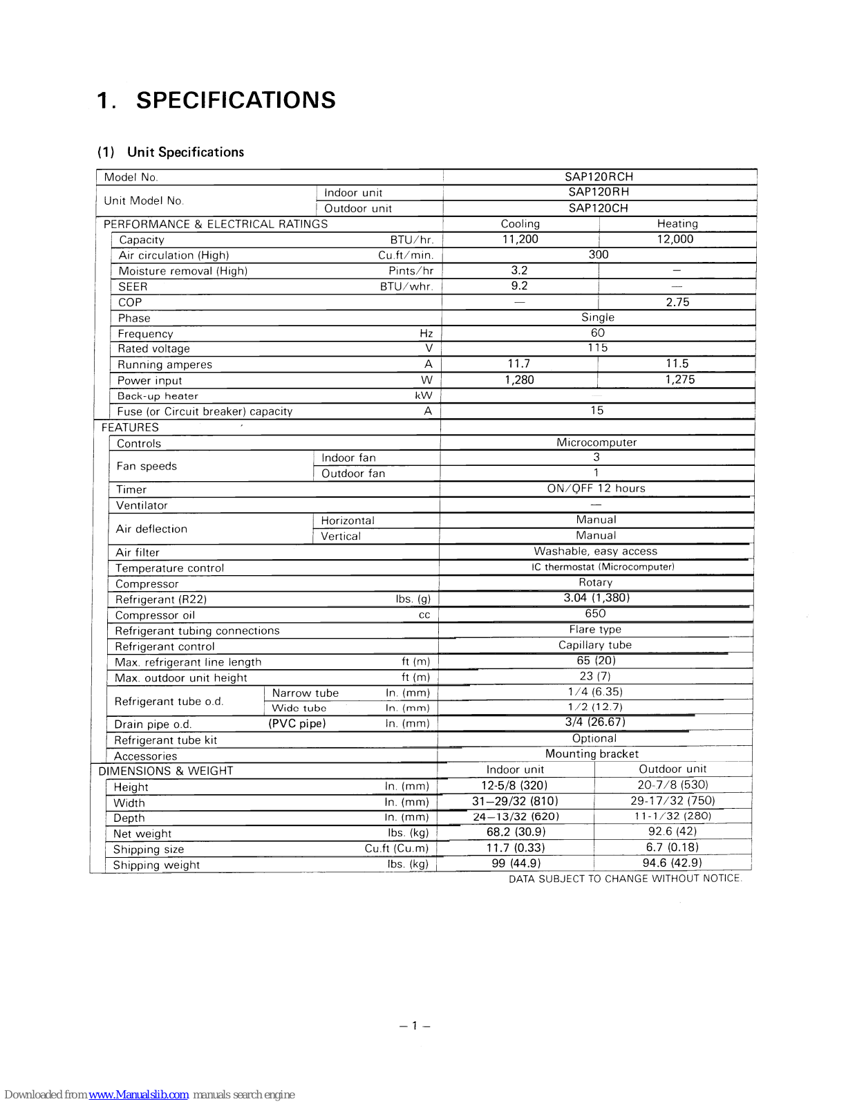
(1) Unit Specifications
| Model No. | SAP120RCH | ||||
|---|---|---|---|---|---|
| Indoor unit | SAP120RH | ||||
| Unit Model No. | - | Outdoor unit | SAP | SAP120CH | |
| PERFORMANCE & ELECTRICAL RATINGS | Cooling | Heating | |||
| Capacity | BTU/hr. | 11,200 | 12,000 | ||
| Air circulation (High) | Cu.ft/min. | 300 | |||
| Moisture removal (High) | Pints/hr | 3.2 | _ | ||
| SEER | BTU/whr. | 9.2 | |||
| СОР | 2.75 | ||||
| Phase | Si | Single | |||
| Frequency | Hz | 60 | |||
| Rated voltage | V | 1 | 15 | ||
| Running amperes | A | 11.7 | 11.5 | ||
| Power input | W | 1,280 | 1,275 | ||
| Back-up heater | kW | • | .k | ||
| Fuse (or Circuit breaker) ca | pacity | А | 15 | ||
| FEATURES | • • | ||||
| Controls | Microc | omputer | |||
| 1 | ndoor fan | 3 | |||
| Fan speeds | Outdoor fan | 1 | |||
| Timer | ON/QFF 12 hours | ||||
| Ventilator | |||||
| H | lorizontal | Ma | nual | ||
| Air deflection | /ertical | Ma | nual | ||
| Air filter | Washable, | easy access | |||
| Temperature control | IC thermostat | (Microcomputer) | |||
| Compressor | Ro | tary | |||
| Refrigerant (R22) | lbs. (g) | 3.04 | (1,380) | ||
| Compressor oil | CC | 6 | 650 | ||
| Refrigerant tubing connecti | ions - | Flare type | |||
| Refrigerant control | Capillary tube | ||||
| Max. refrigerant line length | ۱ | ft (m) | 65 (20) | ||
| Max. outdoor unit height | ft (m) | 23 | (7) | ||
| Narrow tu | ibe In. (mm) | 1/4 | (6.35) | ||
| Ketrigerant tube o.d. | Wide tube | ln. (mm) | 1/2 | (12.7) | |
| Drain pipe o.d. | (PVC pipe) | In. (mm) | 3/4 (2 | 26.67) | |
| Refrigerant tube kit | Opti | onal | |||
| Accessories | Mounting | g bracket | |||
| DIMENSIONS & WEIGHT | Indoor unit | Outdoor unit | |||
| Height | In. (mm) | 12-5/8 (320) | 20-7/8 (530) | ||
| Width | In. (mm) | 31-29/32 (810) | 29-17/32 (750) | ||
| Depth | In. (mm) | 24-13/32 (620) | 11-1/32 (280) | ||
| Net weight | lbs. (kg) | 68.2 (30.9) | 92.6 (42) | ||
| Shipping size | Cu.ft (Cu.m) | 11.7 (0.33) | 6.7 (0.18) | ||
| Shipping weight | lbs. (kg) | 99 (44.9) | 94.6 (42.9) | ||
DATA SUBJECT TO CHANGE WITHOUT NOTICE.
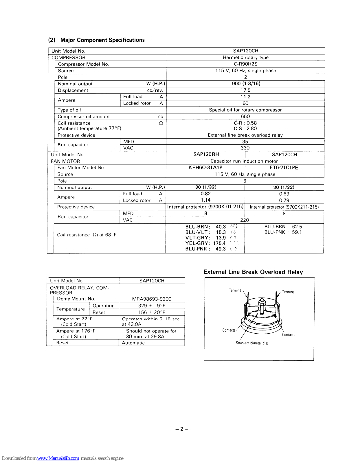
(2) Major Component Specifications
| Ur | nit Model No | SAP1 | 20CH | ||
|---|---|---|---|---|---|
| CC | COMPRESSOR | Hermetic | Hermetic rotary type | ||
| Compressor Model No. | C-R90H2S | ||||
| Source | 115 V, 60 Hz, single phase | ||||
| Pole | 2 | 2 | |||
| Nominal output | W ( | H.P.) | 900 (1-3/16) | ||
| Displacement | CC/ | rev. | 17.5 | ||
| A | Full load | Α | 11.2 | ||
| Ampere | Locked rotor | Α | 6 | 0 | |
| Type of oil | Special oil for ro | tary compressor | |||
| Compressor oil amount | сс | 65 | 0 | ||
|
Coil resistance
(Ambient temperature 77°F |
) | Ω |
C-R :
C-S : |
0.58
2.80 |
|
| Protective device | External line brea | ak overload relay | |||
| Bun canacitor | MFD | 35 | |||
| VAC | 330 | ||||
| Un | nit Model No. | SAP120RH | SAP120CH | ||
| FA | N MOTOR | Capacitor run in | iduction motor | ||
| Fan Motor Model No. | KFH6Q-31A1P | FT6-21C1PE | |||
| Source | 115 V, 60 Hz, single phase | ||||
| Pole | 6 | ||||
| Nominal output | W ( | H.P.) | 30 (1/32) | 20 (1/32) | |
| Ampere | Full load | А | 0.82 | 0.69 | |
| Locked rotor | A | 1.14 | 0.79 | ||
| Protective device | Internal protector (9700K-01-215) | Internal protector (9700K211-215) | |||
| Run capacitor MFD | 8 | 8 | |||
| VAC | 220 | ||||
| Coil resistance (Ω) at 68 F |
BLU-BRN: 40.3 47
BLU-VLT: 15.3 / 6 VLT-GRY: 13.9 59 YEL-GRY: 175.4 57 BLU-PNK: 49.3 4 3 |
BLU-BRN : 62.5
BLU-PNK : 59.1 |
|||
| Unit Model No. | SAP120CH | ||
|
OVERLOAD RELAY, COM-
PRESSOR |
AY, COM⊦ | ||
| Dome Mount N | No. | MRA98693-9200 | |
| Tomporaturo | Operating | 329 ± 9°F | |
| remperature | Reset | 156 ± 20°F | |
|
Ampere at 77°Γ
(Cold Start) |
۲ |
Operates within 6-16 sec.
at 43.0A |
|
|
Ampere at 176°F
(Cold Start) |
Should not operate for 30 min. at 29.8A | ||
| Reset | Automatic | ||
External Line Break Overload Relay

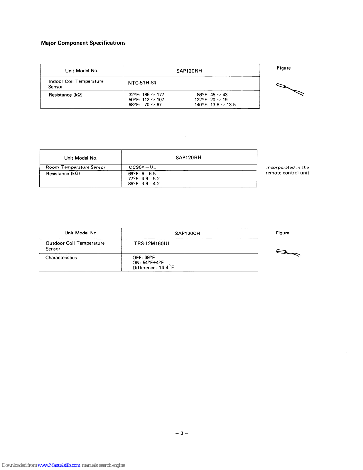
Major Component Specifications
| Unit Model No. | SAP120RH | Figure | |
|---|---|---|---|
|
Indoor Coil Temperature
Sensor |
NTC-51H-S4 | ||
| Resistance (kQ) |
32°F: 186 ∼ 177
50°F: 112 ∼ 107 68°F: 70 ∼ 67 |
86°F: 45 ∼ 43
122°F: 20 ∼ 19 140°F: 13.8 ∼ 13.5 |
| Unit Model No. | SAP120RH | |
|---|---|---|
| Room Temperature Sensor | OCS5K-UL | Incorporated in the |
| Resistance (kΩ) |
69°F: 6–6.5
77°F: 4.9–5.2 86°F: 3.9–4.2 |
remote control unit |
| Unit Model No. | SAP120CH | Figure |
|---|---|---|
|
Outdoor Coil Temperature
Sensor |
TRS-12M160UL | |
| Characteristics |
OFF: 39°F
ON: 54°F±4°F Difference: 14.4°F |

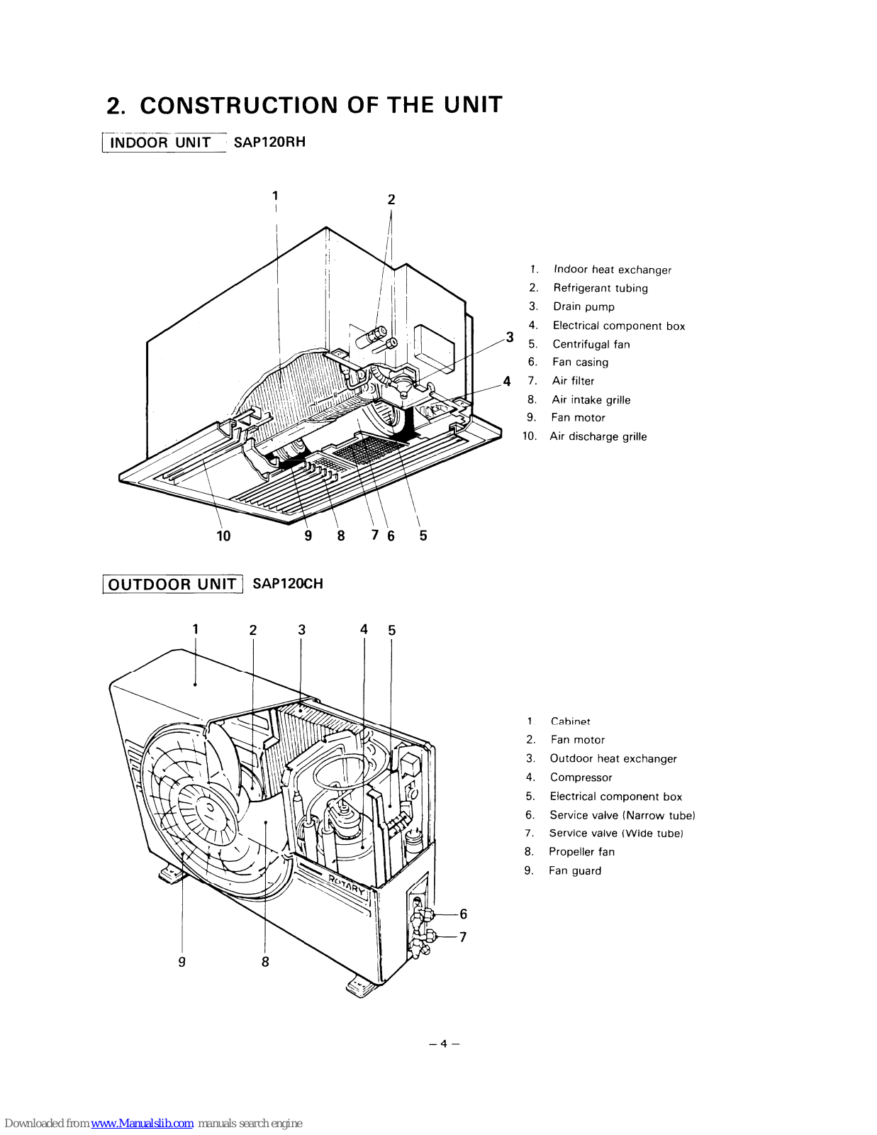
2. CONSTRUCTION OF THE UNIT
INDOOR UNIT SAP120RH

OUTDOOR UNIT SAP120CH

- 1 Cabinat
- 2. Fan motor
- 3. Outdoor heat exchanger
- 4. Compressor
- 5. Electrical component box
- 6. Service valve (Narrow tube)
- 7. Service valve (Wide tube)
- 8. Propeller fan
- 9. Fan guard
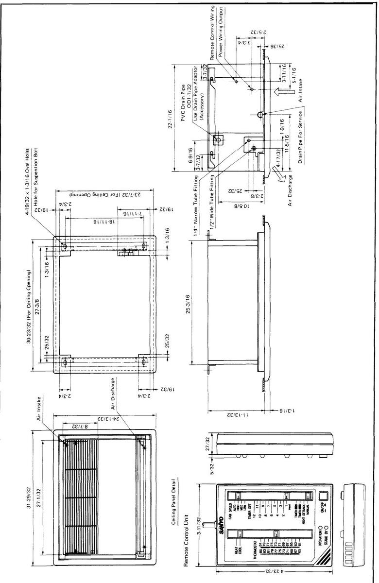
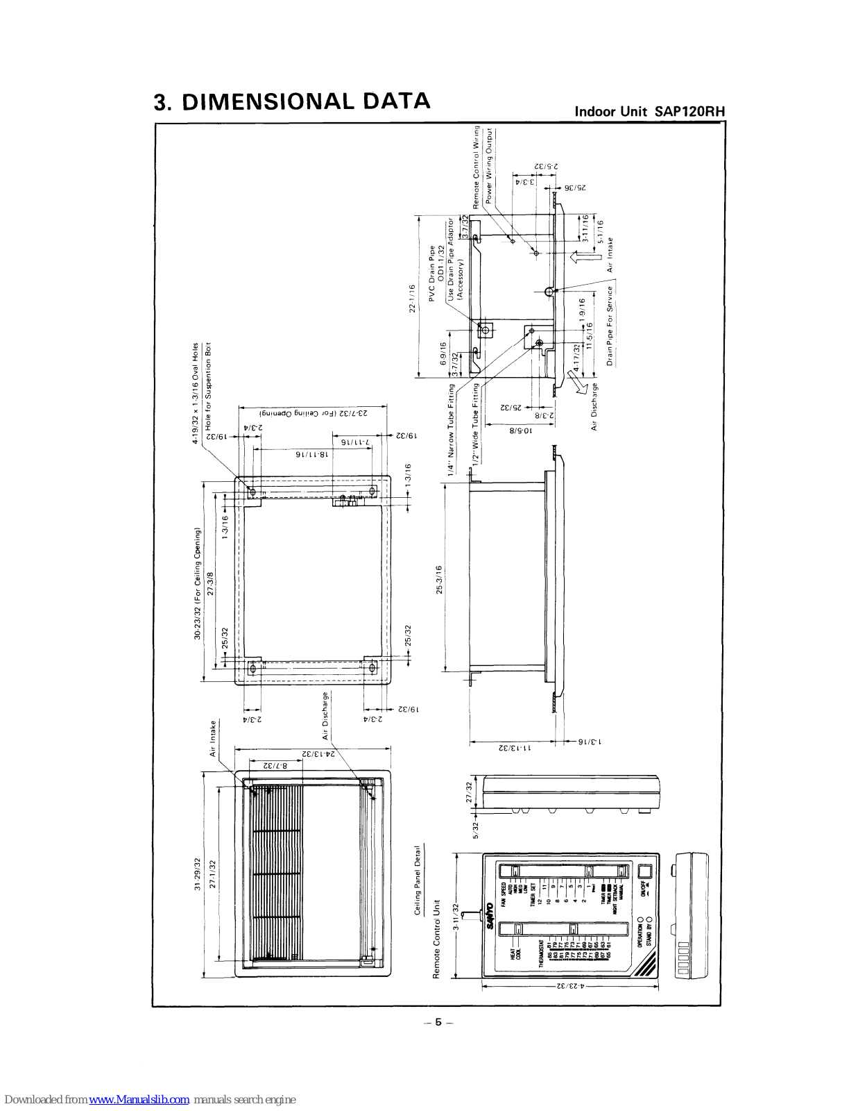
3. DIMENSIONAL DATA
Indoor Unit SAP120RH
5


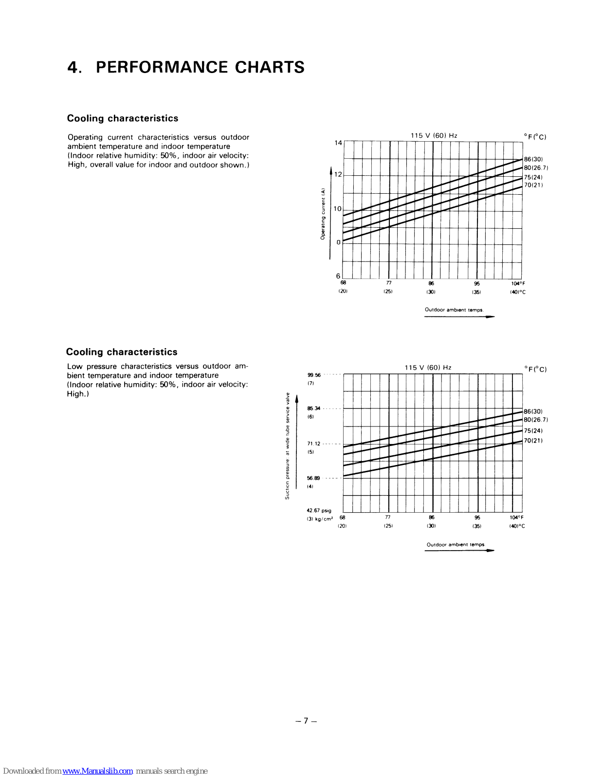
4. PERFORMANCE CHARTS
Cooling characteristics
Operating current characteristics versus outdoor ambient temperature and indoor temperature (Indoor relative humidity: 50%, indoor air velocity: High, overall value for indoor and outdoor shown.)

Cooling characteristics
Low pressure characteristics versus outdoor ambient temperature and indoor temperature (Indoor relative humidity: 50%, indoor air velocity: High.)

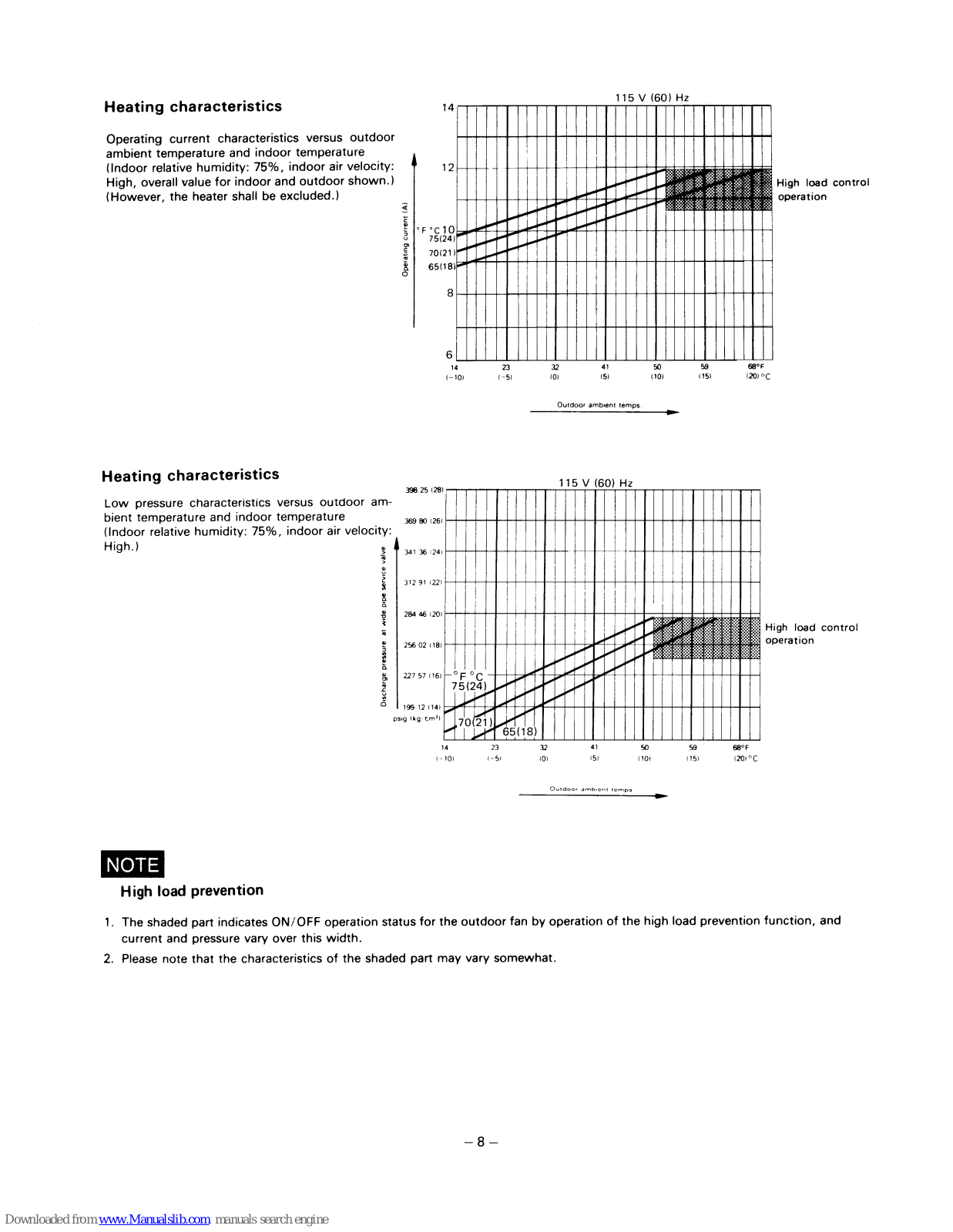
Heating characteristics
Operating current characteristics versus outdoor ambient temperature and indoor temperature (Indoor relative humidity: 75%, indoor air velocity: High, overall value for indoor and outdoor shown.) (However, the heater shall be excluded.)

Heating characteristics
Low pressure characteristics versus outdoor ambient temperature and indoor temperature (Indoor relative humidity: 75%, indoor air velocity: High.) High.) High load control provide (10) High load control Provide (10) High load control Provide (10) High load control Provide (10) High load control Provide (10) High load control Provide (10) High load control Provide (10) High load control Provide (10) High load control Provide (10) High load control Provide (10) High load control Provide (10) High load control Provide (10) High load control Provide (10) High load control Provide (10) High load control High load control Provide (10) High load control Provide (10) High load control Provide (10) High load control Provide (10) High load control Provide (10) High load control Provide (10) High load control Provide (10) High load control Provide (10) High load control Provide (10) High load control Provide (10) High load control Provide (10) High load control Provide (10) High load control Provide (10) High load control Provide (10) High load control Provide (10) High load control Provide (10) High load control Provide (10) High load control Provide (10) High load control Provide (10) High load control Provide (10) High load control Provide (10) High load control Provide (10) High load control Provide (10) High load control Provide (10) High load control Provide (10) High load control Provide (10) High load control Provide (10) High load control Provide (10) High load control Provide (10) High load control Provide (10) High load control Provide (10) High load control Provide (10) High load control Provide (10) High load control Provide (10) High load control Provide (10) High load control Provide (10) High load control Provide (10) High load
NOTE
High load prevention
- 1. The shaded part indicates ON/OFF operation status for the outdoor fan by operation of the high load prevention function, and current and pressure vary over this width.
- 2. Please note that the characteristics of the shaded part may vary somewhat.
5. OPERATING INSTRUCTIONS
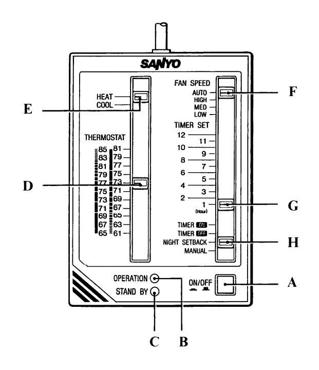
Controls and Indicators
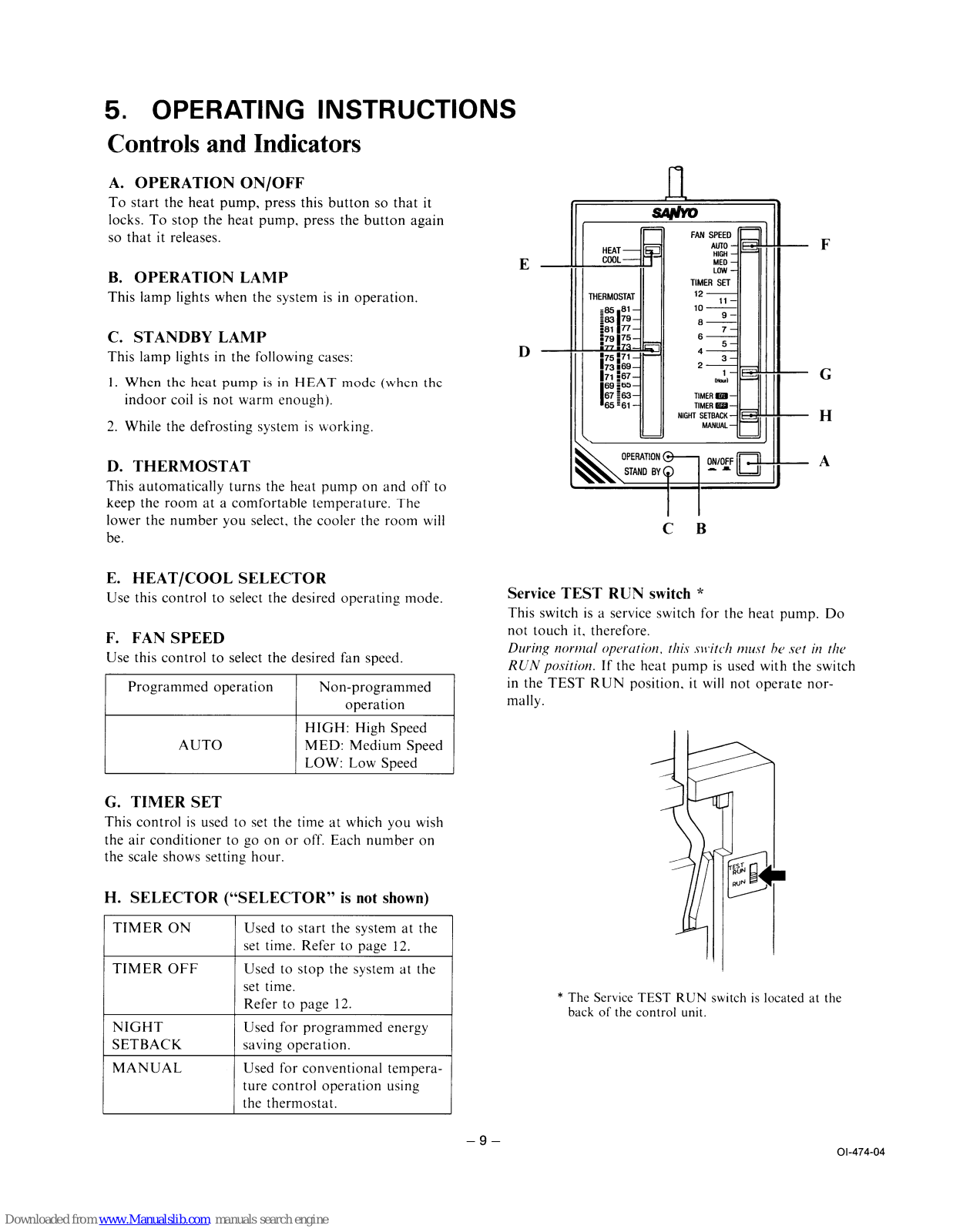
A. OPERATION ON/OFF
To start the heat pump, press this button so that it locks. To stop the heat pump, press the button again so that it releases.
B. OPERATION LAMP
This lamp lights when the system is in operation.
C. STANDBY LAMP
This lamp lights in the following cases:
- 1. When the heat pump is in HEAT mode (when the indoor coil is not warm enough).
- 2. While the defrosting system is working.
D. THERMOSTAT
This automatically turns the heat pump on and off to keep the room at a comfortable temperature. The lower the number you select, the cooler the room will be.
E. HEAT/COOL SELECTOR
Use this control to select the desired operating mode.
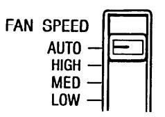
F. FAN SPEED
Use this control to select the desired fan speed.
| Programmed operation | Non-programmed operation |
|---|---|
| AUTO |
HIGH: High Speed
MED: Medium Speed LOW: Low Speed |
G. TIMER SET
This control is used to set the time at which you wish the air conditioner to go on or off. Each number on the scale shows setting hour.
H. SELECTOR ("SELECTOR" is not shown)
| TIMER ON | Used to start the system at the set time. Refer to page 12. |
|---|---|
| TIMER OFF |
Used to stop the system at the
set time. Refer to page 12. |
|
NIGHT
Setback |
Used for programmed energy saving operation. |
| MANUAL |
Used for conventional tempera-
ture control operation using the thermostat. |
Service TEST RUN switch *
This switch is a service switch for the heat pump. Do not touch it, therefore.
During normal operation, this switch must be set in the RUN position. If the heat pump is used with the switch in the TEST RUN position, it will not operate normally.

* The Service TEST RUN switch is located at the back of the control unit.
COOLING
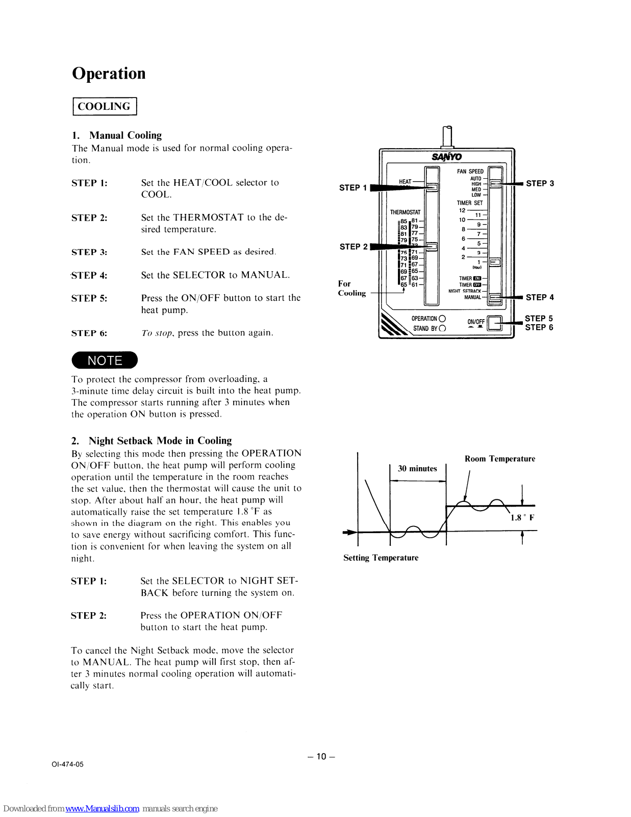
1. Manual Cooling
The Manual mode is used for normal cooling operation.
| STEP 1: | Set the HEAT/COOL selector to COOL. |
|---|---|
| STEP 2: |
Set the THERMOSTAT to the de-
sired temperature. |
| STEP 3: | Set the FAN SPEED as desired. |
| STEP 4: | Set the SELECTOR to MANUAL. |
| STEP 5: | Press the ON/OFF button to start th heat pump. |
| STEP 6: | To stop, press the button again. |
NOTE
To protect the compressor from overloading, a 3-minute time delay circuit is built into the heat pump. The compressor starts running after 3 minutes when the operation ON button is pressed.
2. Night Setback Mode in Cooling
By selecting this mode then pressing the OPERATION ON/OFF button, the heat pump will perform cooling operation until the temperature in the room reaches the set value, then the thermostat will cause the unit to stop. After about half an hour, the heat pump will automatically raise the set temperature 1.8 °F as shown in the diagram on the right. This enables you to save energy without sacrificing comfort. This function is convenient for when leaving the system on all night.
STEP 1: Set the SELECTOR to NIGHT SET-BACK before turning the system on.
STEP 2: Press the OPERATION ON/OFF button to start the heat pump.
To cancel the Night Setback mode, move the selector to MANUAL. The heat pump will first stop, then after 3 minutes normal cooling operation will automatically start.


Setting Temperature
ADJUSTING THE FAN SPEED
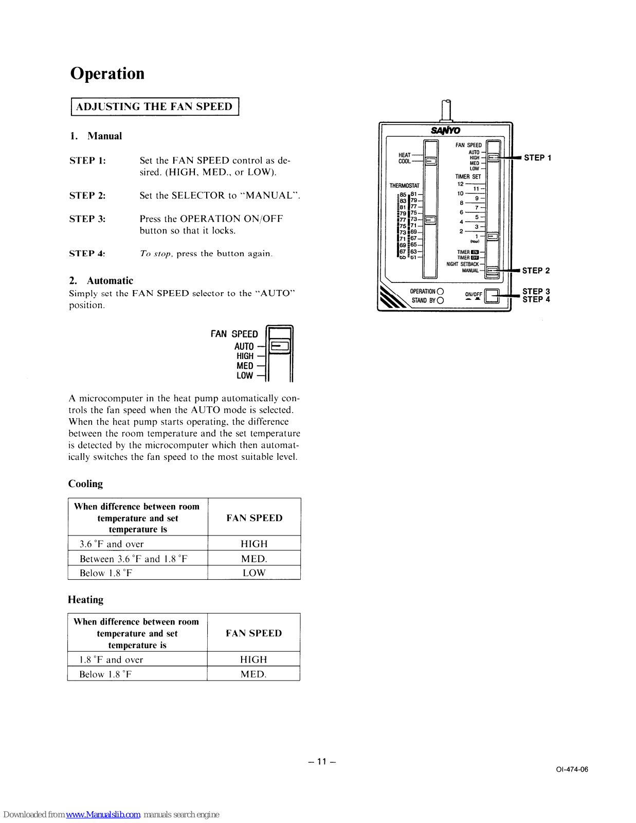
1. Manual
| STEP 1: |
Set the FAN SPEED control as de-
sired. (HIGH, MED., or LOW). |
|---|---|
| STEP 2: | Set the SELECTOR to "MANUAL" |
| STEP 3: | Press the OPERATION ON/OFF button so that it locks. |
| STEP 4: | To stop, press the button again. |
2. Automatic
Simply set the FAN SPEED selector to the "AUTO" position.
A microcomputer in the heat pump automatically controls the fan speed when the AUTO mode is selected. When the heat pump starts operating, the difference between the room temperature and the set temperature is detected by the microcomputer which then automatically switches the fan speed to the most suitable level.
Cooling
|
When difference between room
temperature and set temperature is |
FAN SPEED |
|---|---|
| 3.6 °F and over | HIGH |
| Between 3.6 °F and 1.8 °F | MED. |
| Below 1.8 °F | LOW |
Heating
|
When difference between room
temperature and set temperature is |
FAN SPEED |
|---|---|
| 1.8 °F and over | HIGH |
| Below 1.8 °F | MED. |

USING THE TIMER
1. Timer Off Mode
The system stops at the set time.
STEP 1: Set the SELECTOR to TIMER OFF.

STEP 2: Set the TIMER SET control to the desired time.
When the timer is set to 6, for instance, the system stops after six hours.
STEP 3: Press the OPERATION ON/OFF button so that it locks.
2. Timer On Mode
The system starts at the set time.
STEP 1: Set the SELECTOR to TIMER ON.

STEP 2: Set the TIMER SET control to the desired time.
When the timer is set to 6, for instance, the system starts after six hours.
STEP 3: Press the OPERATION ON/OFF button so that it locks.
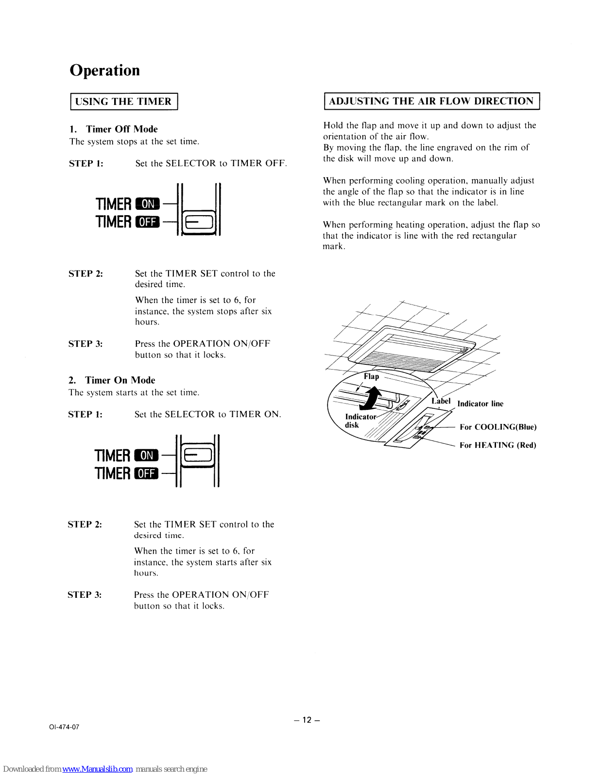
ADJUSTING THE AIR FLOW DIRECTION
Hold the flap and move it up and down to adjust the orientation of the air flow.
By moving the flap, the line engraved on the rim of the disk will move up and down.
When performing cooling operation, manually adjust the angle of the flap so that the indicator is in line with the blue rectangular mark on the label.
When performing heating operation, adjust the flap so that the indicator is line with the red rectangular mark.

HEATING
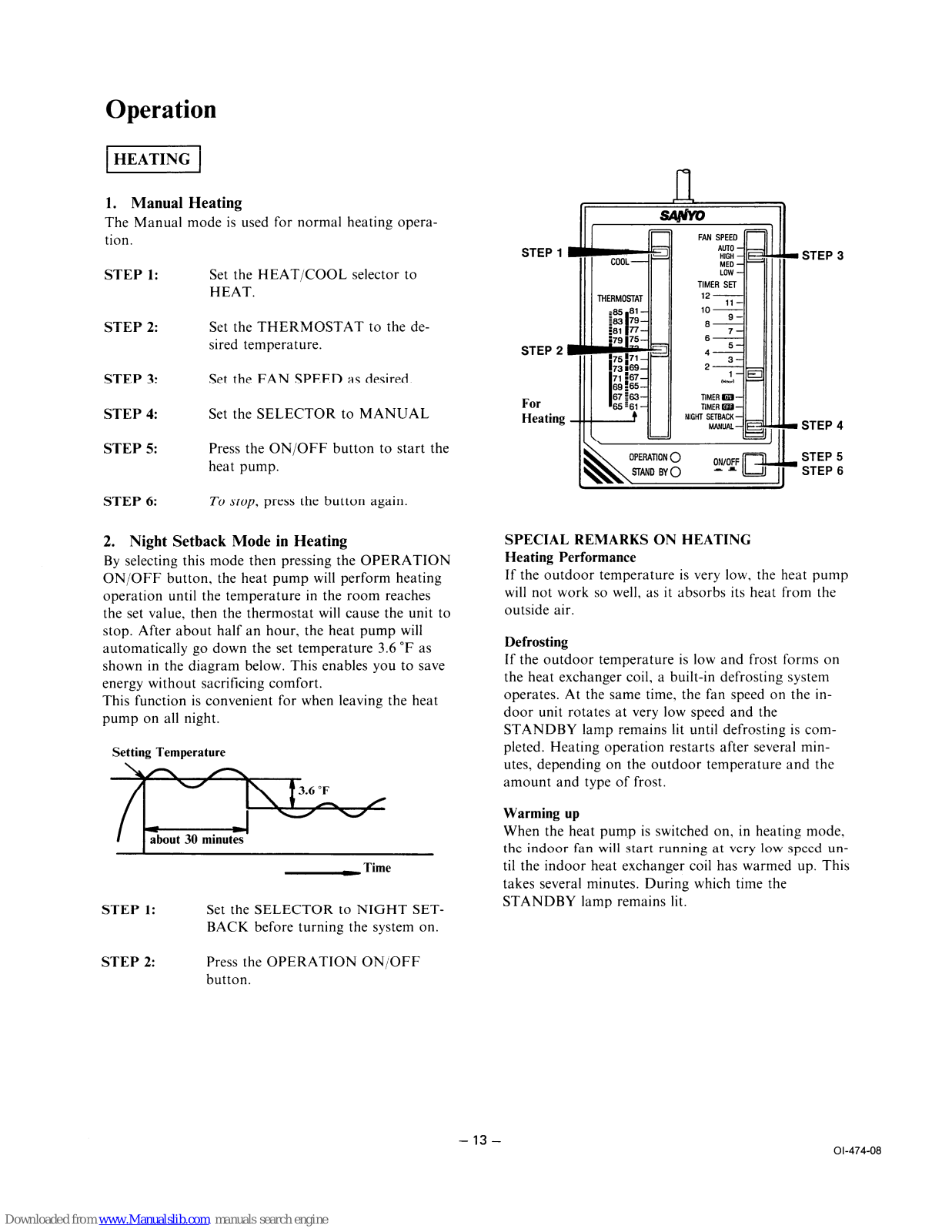
1. Manual Heating
The Manual mode is used for normal heating operation.
| STEP 1: | Set the HEAT/COOL selector to HEAT. |
|---|---|
| STEP 2: |
Set the THERMOSTAT to the de-
sired temperature. |
| STEP 3: | Set the FAN SPEED as desired. |
| STEP 4: | Set the SELECTOR to MANUAL |
| STEP 5: | Press the ON/OFF button to start th heat pump. |
| STEP 6: | To stop, press the button again. |
2. Night Setback Mode in Heating
By selecting this mode then pressing the OPERATION ON/OFF button, the heat pump will perform heating operation until the temperature in the room reaches the set value, then the thermostat will cause the unit to stop. After about half an hour, the heat pump will automatically go down the set temperature 3.6 °F as shown in the diagram below. This enables you to save energy without sacrificing comfort.
This function is convenient for when leaving the heat pump on all night.

- STEP 1: Set the SELECTOR to NIGHT SET-BACK before turning the system on.
- STEP 2: Press the OPERATION ON/OFF button.

SPECIAL REMARKS ON HEATING
Heating Performance
If the outdoor temperature is very low, the heat pump will not work so well, as it absorbs its heat from the outside air.
Defrosting
If the outdoor temperature is low and frost forms on the heat exchanger coil, a built-in defrosting system operates. At the same time, the fan speed on the indoor unit rotates at very low speed and the STANDBY lamp remains lit until defrosting is completed. Heating operation restarts after several minutes, depending on the outdoor temperature and the amount and type of frost.
Warming up
When the heat pump is switched on, in heating mode, the indoor fan will start running at very low speed until the indoor heat exchanger coil has warmed up. This takes several minutes. During which time the STANDBY lamp remains lit.
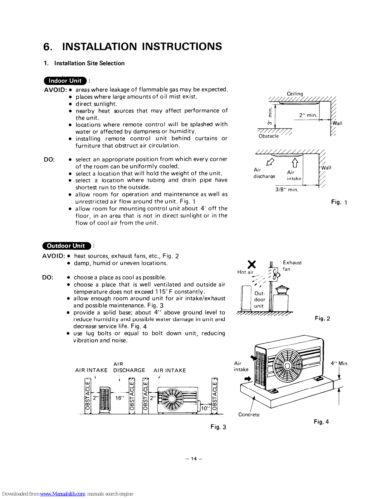
6. INSTALLATION INSTRUCTIONS
1. Installation Site Selection
Indoor Unit :
AVOID: • areas where leakage of flammable gas may be expected.
- places where large amounts of oil mist exist.
- direct sunlight.
- nearby heat sources that may affect performance of the unit.
- locations where remote control will be splashed with water or affected by dampness or humidity.
- installing remote control unit behind curtains or furniture that obstruct air circulation.
-
DO:
select an appropriate position from which every corner of the room can be uniformly cooled.
- select a location that will hold the weight of the unit.
- select a location where tubing and drain pipe have shortest run to the outside.
- allow room for operation and maintenance as well as unrestricted air flow around the unit. Fig. 1
- allow room for mounting control unit about 4' off the floor, in an area that is not in direct sunlight or in the flow of cool air from the unit.
Outdoor Unit :
AVOID: • heat sources, exhaust fans, etc., Fig. 2
ALB INTAKE DISCHARGE
- damp, humid or uneven locations.
-
DO:
choose a place as cool as possible.
- choose a place that is well ventilated and outside air temperature does not exceed 115° F constantly.
- allow enough room around unit for air intake/exhaust and possible maintenance. Fig. 3
- provide a solid base; about 4" above ground level to reduce humidity and possible water damage in unit and decrease service life. Fig. 4
- use lug bolts or equal to bolt down unit, reducing vibration and noise.
AIR INTAKE


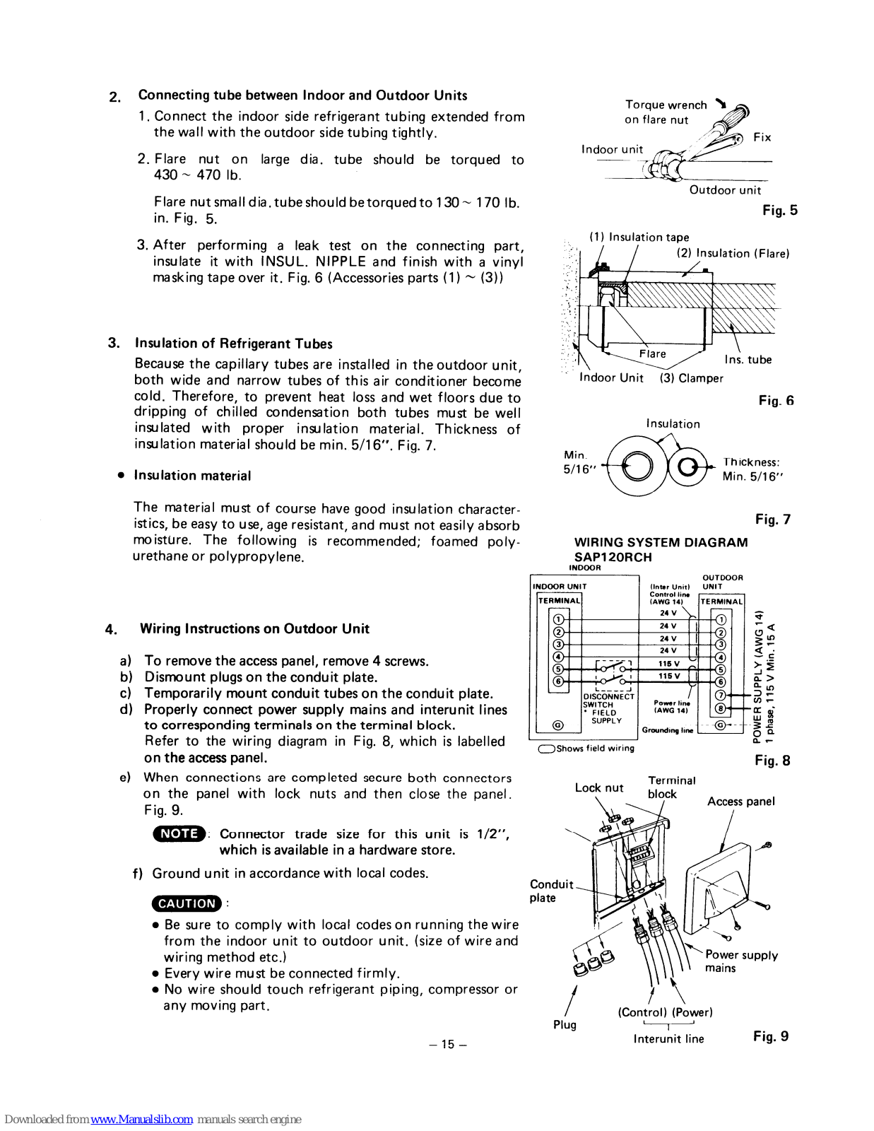
2. Connecting tube between Indoor and Outdoor Units
- 1. Connect the indoor side refrigerant tubing extended from the wall with the outdoor side tubing tightly.
- 2. Flare nut on large dia, tube should be torqued to 430 ~ 470 lb.
Flare nut small dia, tube should be torqued to 130 ~ 170 lb. in. Fig. 5.
3. After performing a leak test on the connecting part, insulate it with INSUL. NIPPLE and finish with a vinyl masking tape over it. Fig. 6 (Accessories parts (1) ~ (3))
3. Insulation of Refrigerant Tubes
Because the capillary tubes are installed in the outdoor unit, both wide and narrow tubes of this air conditioner become cold. Therefore, to prevent heat loss and wet floors due to dripping of chilled condensation both tubes must be well insulated with proper insulation material. Thickness of insulation material should be min. 5/16". Fig. 7.
Insulation material
The material must of course have good insulation characteristics, be easy to use, age resistant, and must not easily absorb moisture. The following is recommended; foamed polyurethane or polypropylene.
4. Wiring Instructions on Outdoor Unit
- a) To remove the access panel, remove 4 screws.
- b) Dismount plugs on the conduit plate.
- c) Temporarily mount conduit tubes on the conduit plate.
- d) Properly connect power supply mains and interunit lines to corresponding terminals on the terminal block. Refer to the wiring diagram in Fig. 8, which is labelled on the access panel.
- e) When connections are completed secure both connectors on the panel with lock nuts and then close the panel. Fig. 9.
NOTE : Connector trade size for this unit is 1/2", which is available in a hardware store.
f) Ground unit in accordance with local codes.
CAUTION :
- Be sure to comply with local codes on running the wire from the indoor unit to outdoor unit. (size of wire and wiring method etc.)
- Every wire must be connected firmly.
- No wire should touch refrigerant piping, compressor or any moving part.
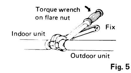


Fig. 7
WIRING SYSTEM DIAGRAM SAP120RCH


5. Air Purging
Air does not function as a refrigerant because it cannot be liquefied in the condenser. Air and moisture remaining in the refrigerant system have undesirable effects mentioned below. Therefore, they must be purged completely.
- The pressure on the parrow pipe rises
- The operating current rises.
- Cooling and heating efficiency drops.
- Water contained in the air may freeze and block the capillary tubing.
- Water may lead to corrosion of parts in the refrigerant circuit.

Air Purging Procedure (conventional evacuation system)
- a) Check gas leakage of all joints with liquid soap. Fig. 11.
- b) If no gas leakage is confirmed, connect both vacuum pump and vacuum gauge to service valve through 1/4" port with a flare nut, Fig. 10.
- c) Next run the vacuum pump until the pressure reaches to 1.5 mmHg abs, or less valve than that.
- d) Close the low pressure side knob on the gauge manifold valve and stop evacuation
- e) Remove the cap from the gas line service valve and turn the spindle gradually until it is back seated. Fig. 12.
- f) Disconnect vacuum pump and gauge manifold valve from the service valve. Then replace bonnet and flare nut to 1/4" ports of service valve.
- a) The stem of liquid line service valve shall be fully back seated Then tighten the valve seal cap with the copper gasket
- h) The all air purge procedure has been completed and the unit is ready for trial operation.
- 16 -

Fig. 11

Fig. 12
■ SERVICE VALVE CONSTRUCTION
Valve Position -a-
The valve stems of both wide & narrow tubes are turned all the way in. The unit is shinned from the factory in this position. (Fig. 13-a)
• Valve Position -b-
The valve stems of both wide & narrow tubes are turned all the way out ("BACK SEAT" position). This is the normal operating position. (Fig. 13-b)
Valve Position -c-
With the narrow tube valve kept at BACK SEAT only the wide tube valve stem is turned halfway-down position. This position is used for pressure measurement and gas charging. (Fig. 13-c)
Valve Position -d-
Like position -a-, but with the flare nut of wide tube open. This position is used for air purging. (Fig. 13-d)


Pump down means collecting all refrigerant in the system back into the outdoor unit without losing refrigerant gas, Pump down is used when unit is moved or for servicing the refrigerant circuit.
- 1) Close valve on wide tube halfway (2 turns).
- 2) Close valve on narrow tube all the way (4 turns). 3) Turn unit on (cooling) for approximately 3 minutes then shut off.
- 4) Close valve on wide tube all the way (2 additional turns)
- 5) Disconnect tubes slowly allowing pressure to equalize inside and out.
- 6) When tubing is disconnected, provide dust covers for both valves and tubes until unit is reconnected.
7. TROUBLESHOOTING
– Quick Access Index –
Page
| 1. |
Aii
1) 2) |
r conditioner does not operate 19 Circuit breaker trips (or fuse blows) 19 ① When circuit breaker is set to ON, it is tripped soon (Resetting is not possible) 19 ② Circuit breaker trips when the operation switch is depressed 20 Neither indoor unit nor outdoor unit runs 21 |
|---|---|---|
| 2. |
So
1) 2) 3) 4) 5) 6) |
me part of air conditioner does not operate22Indoor fan does not run22Neither outdoor fan nor compressor runs23Only outdoor fan does not run24Only compressor does not run25Compressor frequently repeats ON and OFF26Air conditioner will not enter into heating mode (Only cooling is possible)27① Heating operation cannot be done (4-way reversing valve malfunction)27② Defrosting system malfunction (at heating)27 |
| 3. |
Air
1) 2) 3) |
r conditioner operates, but abnormalities are observed |
1) Circuit Breaker trips (or fuse blows)
(1) When circuit breaker is set to ON, it is tripped soon (Resetting is not possible)

- 19 --
② Circuit breaker trips when the operation switch is depressed.
2) Neither indoor unit nor outdoor unit runs

- 21 -
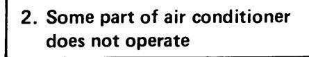
1) Indoor fan does not run

2) Neither outdoor fan nor compressor runs
Note: Check following points at first.
- 1. Is thermostat setting suitable?
-
2. Has 3 minute timer operated?
- (No operation for 3 minutes after power ON.)

- 23 -
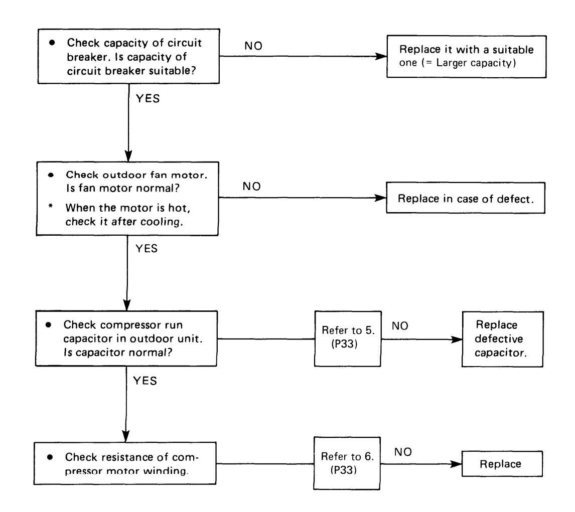
3) Only outdoor fan does not run

4) Only compressor does not run

5) Compressor frequently repeats ON and OFF
(Only compressor repeats ON and OFF, while indoor unit and outdoor fan runs without fail.)

2) Excessive cooling

8. CHECKING AND REPLACING ELECTRICAL COMPONENTS
- Quick Access Index -
| Page | ||
|---|---|---|
| 1. | Measurement of Insulation Resistance of the Unit | · 32 |
| 2. | Measurement of Insulation Resistance of the Compressor | · 32 |
| 3. | Measurement of Insulation Resistance of the Fan Motor | · 32 |
| 4. | Checking of the Outdoor Fan Motor | · 33 |
| 5. | Checking of the Motor Capacitor | · 33 |
| 6. | Checking of the Compressor Motor Winding | · 33 |
| 7. | Checking of the Control Unit Proper | · 34 |
| 8. | Checking of the Continuity of Fuse on the Controller PCB | · 36 |
| 9. | Method to Replace Fuse on the Controller PCB | · 36 |
| 10. | Checking of the Output of the Controller PCB for Fan Motor Terminals | · 36 |
| 11. | Checking of the Power Transformer | 37 |
| 12. | Checking of the Indoor Fan Motor | 37 |
| 13. | Checking of the Compressor Overload Relay (Protector) | 37 |
| 14. | Checking of the Drain Pump | 37 |
1. Measurement of Insulation Resistance of the l Init
Turn off Power supply (terminal (7) and (8) on the outdoor terminal nlate)
Clamp the gound (GND) line of the Power Line with a lead clip of the insulation resistance tester and measure the resistance by placing a probe on either of the two power lines. (terminal 7) and 8).)
Then also measure the resistance between the GND line and the other power line. The insulation is in good condition if the resistance exceeds 1 MO Fig. 1
2. Measurement of Insulation Resistance of the Compressor
Remove the red lead wire connected to the compressor motor from power relay (terminal). Clamp the removed red lead wire with a lead clip of the insulation resistance tester and measure the resistance by placing a probe of the tester to the terminal GND, to which green lead wire is connected.
The insulation is in good condition if the resistance exceeds 1 MΩ. Fig. 2.
3. Measurement of Insulation Resistance of the Fan Motor
1) In case of indoor fan motor
Remove the fan motor connector (5P-FM) from controller PCB (P.51) clamp the green lead wire (at the bear section) extended from the terminal GND in the electrical component box and measure insulation resistance by placing a probe of the insulation tester to either pole of this
The insulation is in good condition if the resistance exceeds 1 MΩ. Fig. 3.
NOTE
If the probe does not enter the pole because the hole is too narrow then use a probe with a thinner pin.
2) In case of outdoor fan motor
Remove the black lead wire of the fan motor capacitor connected to CM Capacitor. Clamp this lead wire with a lead clip of the insulation resistance tester and measure the resistance by placing a probe of the tester to the tester to the terminal GND.
The insulation is in good condition if the resistance exceeds 1 MΩ. Fig. 4.


- 32 -
4. Checking of the Outdoor Fan Motor
Remove the blue (BLU) lead wire from the defrost controller 3, then brown (BRN) and pink (PNK) lead wires from the fan motor capacitor respectively as indicated in the wiring diagram. (Refer to P.50)
Set the resistance measuring range of the multimeter to "X1Ω" and measure the resistance between the fan motor lead wires.
| Lead wire color | Coil resistance |
|---|---|
| BLU—BRN | 63Ω ± 10% |
| BLU—PNK | 59Ω ± 10% |
| Table-1 |
NOTE When ambient temp. is 68°F.
5. Checking of the Motor Capacitor
Checking of any of the indoor fan motor capacitor, outdoor fan motor capacitor and compressor motor capacitor can be done by the same method.
Remove both the lead wire terminals connected to the capacitor, place the probe on the capacitor terminals as shown in Fig. 5 and observe the deflection of the pointer, setting the resistance measuring range of the multimeter to the maximum value.
For good condition of the capacitor, the pointer bounces to a great extent and then gradually returns to its original position.
The range of deflection and deflection time differ according to the capacity of the capacitor.
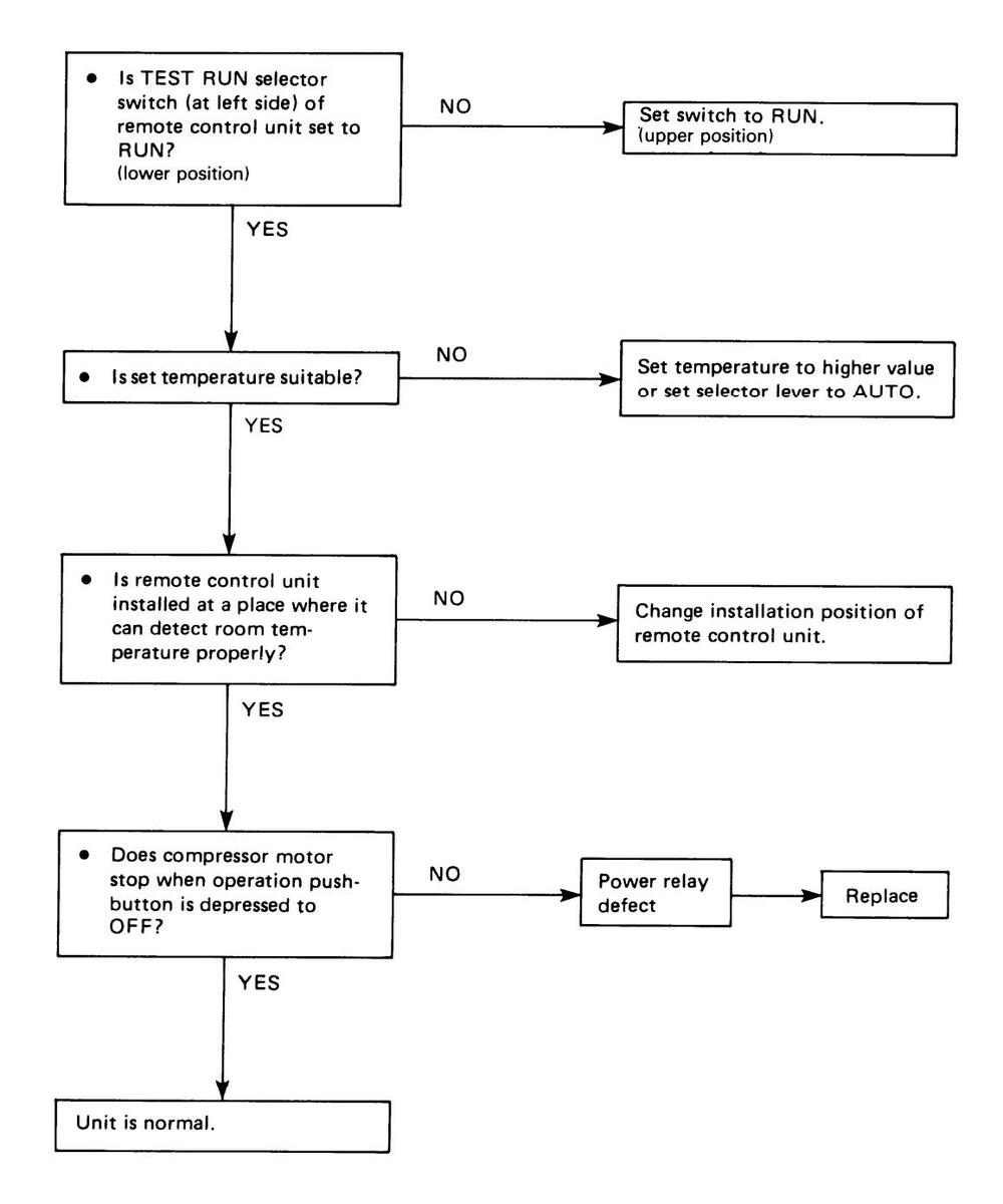
6. Checking of the Compressor Motor Winding
Remove the terminal cover of the compressor motor, set the resistance measuring range of the multimeter to "X1Ω" and check the continuity between each pair out of the 3 terminals as indicated in Fig. 6 and 7.
It is in good working condition if there is continuity among each pair of terminals. Fig. 7.
Compressor Coil Resistance
| Lead wire color | Coil resistance |
|---|---|
| С — R | 0.58 Ω |
| C — S | 2.80 Ω |

Table-2

Fig. 5


- 33 -
7. Checking of the Control Unit Proper (Refer to P. 52)
1) CAUTION : Use of the Test Switch (RUN/TEST RUN)
The position of the switch which is used to operate the air conditioner for a room temperature below 65°F (19°) is the position of the switch for this TEST RUN.
If this operation is continued for a long time, there would be a bad effect on the air conditioner because of overcooling. Therefore, use this switch only for checking, and in any case, DO NOT KEEP ON COOLING FOR MORF THAN 15 MIN. UNDER TEST RUN MODE.
When the checking is over, TURN THE SWITCH BACK TO ITS ORIGINAL POSITION ( = RUN) WITHOUT FAIL.
2) Checking of the Items of the Control Unit
At first, pull out the connectors (12P and 3P) of the control unit from the controller PCB of the unit. (Fig. 8).
(1) Checking of the Room Temperature Sensor (12P-ROOM SENSOR)
Measure the resistance between No. 5 and No. 6 connectors. (For an ambient temperature of 80°F, the resistance is about 5K )
NOTE
If the probe does not enter the pole because the hole is too narrow then use a probe with a thinner pin
(2) Checking of the Fan Speed Selector (12P-EAN SPEED)
Check the continuity of connectors (No. 3 and No. 4 against No. 10 (Place the negative (-) probe on No. 10 and positive (+) probe on No. 3 and then No. 4).
| Checking | Position of the selector | ||||||
|---|---|---|---|---|---|---|---|
| points | High Med. | Low | Auto | ||||
| 10 – 3 | NO | YES | YES | NO | |||
| 10 - 4 | YES | YES | NO | NO | |||
Table-3
Note: YES ..... Continuity NO ..... Discontinuity

ia
(3) Checking of the Selector (12P-SELECTOR)
Check the continuity of connectors No. 3, 1 and 2 against connector No. 9.
| Position of the Selector | ||||||||
|---|---|---|---|---|---|---|---|---|
| Connector No. | NIGHT | TIMER | ||||||
| MANUAL | SET BACK | ON | OFF | |||||
| 9 – 3 | NO | NO | Ϋ́ES | NO | ||||
| 9 — 1 | NO | NO | YES | YES | ||||
| 9 – 2 | NO | YES | NO | NO | ||||
| Table-4 | ||||||||
(4) Checking of the Operation Pushbutton (12P-OPERATION)
The operating switch is in good working condition if there is continuity between No.9 (placing negative (-) probe) and No. 4 (placing positive (+) probe) while the pushbutton is pressed.
5 Checking of the Timer (12P-TIMER)
Measure the continuity between No. 4, 3, 1, 2 and No. 8 (placing the negative (-) probe).
| Position of the Selector | ||||||||||||
|---|---|---|---|---|---|---|---|---|---|---|---|---|
| Connector No. | 1 | 2 | 3 | 4 | 5 | 6 | 7 | 8 | 9 | 10 | 11 | 12 |
| 8 – 4 | - | _ | - | — | Υ | Y | Y | Y | ||||
| 8 – 3 | _ | - | _ | _ | Y | Y | Υ | Υ | Y | Y | Υ | Y |
| 8 – 1 | _ | Υ | Υ | Υ | Y | _ | _ | _ | Υ | Y | ||
| 8 – 2 | Y | Υ | _ | — | Υ | Υ | _ | Υ | Y | |||
| V for VEC - There is continuity | ||||||||||||
Y for YES = There is continuity.
Table-5
6 Checking of the Thermostat (12P-THERMOSTAT)
Measure the cointinuity between No. 4, 3, 1, 2 and No. 7 (placing the negative (-) probe).
| Connector No. | Position of the Selector | ||||||||||
|---|---|---|---|---|---|---|---|---|---|---|---|
| Connector No. |
61
65 |
63
67 |
65
69 |
67
71 |
69
73 |
71
75 |
73
77 |
75
79 |
77
81 |
75
83 |
81
85 |
| 7 – 4 | - | — | — | Υ | Y | Υ | Υ | Υ | Υ | ||
| 7 – 3 | — | Υ | Υ | Υ | Y | Υ | γ | Υ | Υ | _ | |
| 7 1 | Υ | Υ | Υ | — | — | - | Y | Υ | Υ | Υ | |
| 7 – 2 | _ | — | Υ | Υ | — | Υ | Υ | — | — | Υ | |
Y for YES = There is continuity
Table-6
- Checking of the Operation Switch (12P-OPERATION) Check the continuity of connectors No. 11 and No. 12 against No. 9 (placing the negative (-) probe). Table-6A
- (8) Checking of the Operation/Stand-by Lamps (3P-OPERATION/STAND-BY) The operation and stand-by lamps are in good working
condition if there is continuity between connectors No. 1 and No. 2 against connector No. 3.
If there is abnormality during checking at any of the above steps from 1 to 8, replace the control switch unit as it is.
CAUTION :
Do not disassemble the Control Unit
It is supplied as a complete assembly and is carefully adjusted in the factory by skillful workmanship. Inexperienced disassembly will cause trouble and malfunction in the unit.
8. Checking of the continuity of Fuse on the Controller PCB
Check the cointinuity by the multimeter as shown in Fig. 9.
If it is difficult to check in this way, remove the lamp board ass'y connector and then check it.
9. Method of Replace Fuse on the Controller PCB
- 1. Remove the controller PCB according to Disassembly Procedure sect. 5 (P.40)
- Pull out the fuse at the metal clasp by a pair of pliers while heating the soldered leads on the back side of the controller PCB with a soldering iron (30W or 60W). Fig. 10.
- Remove the fuse ends one by one. For replacement, insert a fuse of the same rating and solder it. (Allow time to radiate heat during soldering so that the fuse does not melt).
CAUTION
Be sure to replace the varistor adjacent to the fuse either when the fuse is blown.
10. Checking of the Output of the Controller PCB for Fan Motor Terminals
Remove the 5P connector coming from the PCB and be sure that there is no danger of short circuit to other parts before supplying electricity to the unit. Then put the operation switch to ON and set the selector to MANUAL.
Now measure the voltage between these pins by the multimeter. The controller PCB is in good working condition if the voltage output becomes same as those shown in the right table.
| Position of the Selector | ||||
|---|---|---|---|---|
| Connector No. | COOL | HEAT | ||
| 9 — 11 | NO | YES | ||
| 9 – 12 | YES | YES | ||
Table-6A

Fig. 9

Fig. 10
| Dair of Dina | FAN | |||||
|---|---|---|---|---|---|---|
| Pair of Pins | Low | Med. | High | |||
| 1 – 4 | * | 0 | 0 | |||
| 1 – 3 | 0 | * | 0 | |||
| 1 – 2 | 0 | 0 | * | |||
| * Line voltage | • | Table-7 | ||||
11. Checking of the Power Transformer
- ① Remove connectors 2P-PRY and 2P-SEC from controller PCB.
- (2) Set the resistance measuring range of multimeter to "X1Ω" and measure the resistance of the lead wires between WHT—WHT and BRN—BRN. (Refer to P.50).
It will be completely satisfactory if all the measured values agree with those indicated in Table-8.
| Lead wires | Value of resistance |
|---|---|
| WHT-WHT | About 143.5 Ω |
| BRN-BRN | 1.2 Ω |
Table-8
12. Checking of the Indoor Fan Motor
Ambient room temp · 70°E
NOTE
Remove the fan motor connector (5P-FM) from controller PCB and measure the resistance between each lead wire of the fan motor connector setting the resistance measuring range to "X1Ω".
The motor is in very good working condition if all the values agree with those indicated in Table-9.
| Lead wires | Value of resistance |
|---|---|
| BLU—BRN | About 40 Ω |
| BLUVLT | 15 Ω |
| VLT—GRY | 14 Ω |
| YEL-GRY | 175 Ω |
| BLU—PNK | 49 Ω |
Table-9
13. Checking of the Compressor Overload Relay (Protector)
Remove both lead wire terminals connected to the compressor overload relay. Set the resistance measuring range of the multimeter to "X1Ω" and check the continuity between terminals of the overload relay. The overload relay is normal if there is a continuity.
14. Checking of the Drain Pump
Remove the drain pump connector (3P-DP) from controller PCB and measure the resistance across the connector No. 1 and No. 3 setting the resistance measuring range "X1Ω". The drain pump is in good working condition if the resistance is about 35Ω.
9. DISASSEMBLY PROCEDURES
| -Quick | Access | Index- |
|---|---|---|
| SAP120RH | Page |
|---|---|
| Top Panel-Removal | |
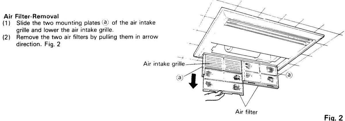
| Air Filter-Removal | |
| Float Switch-Removal | |
| Fan Motor-Removal | 40 |
| Electrical Component Box-Removal | |
| Drain Pump-Removal | |
|
SAP120RH
Top Panel-Removal Air Filter-Removal Float Switch-Removal Fan Motor-Removal Electrical Component Box-Removal Drain Pump-Removal |
OUTDOOR
| 0. | l | |
|---|---|---|
| UNIT | SAP120CH | |
| 7. | Cabinet-Removal | 2 |
| 8. | Fan and Fan Motor-Removal 42 | 2 |
Downloaded from www.Manualslib.com manuals search engine
INDOOR UNIT SAP120RH
Top Panel-Removal Loosen the four screws (a) and remove the top panel by sliding it in arrow direction. Fig. 1

-
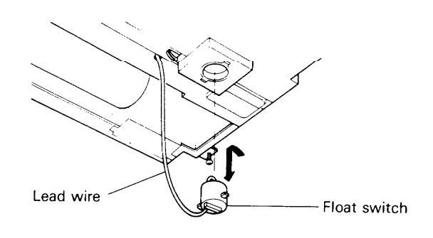
3 Float Switch-Removal
- (1) Separate the lead wire (2P connector).
grille and lower the air intake grille.
direction. Fig. 2
- (2) Turn the float switch to the left and remove it by pulling downward. At this time, take care not to spill the drain water re-
- maining in the float switch. (3) Discharge the drain water and then confirm vertical
- movement of the float switch. Fig. 3
-
4. Fan Motor-Removal
- (1) Remove the two screws (a) fixing the rear panel.
- (2) Remove the four screws (b) (2 each left and right) fixing the fan casing. (3) Loosen the bolt (2) fixing the centrifugal fan and the
- fan motor shaft with a monkey wrench as shown in the figure. Fig. 4
- Fan casino Fan motor Rear panel
Fan motor
(4) The motor can be removed after the two screws fixing the support have been removed. Fig. 5
-
5. Electrical Component Box-Removal
- (1) Remove the two screws (a) of the electrical compo-
- (2) Remove the clamp (b) on the cover plate.
- (3) Remove the electrical component box by pulling it in arrow direction.
- (4) When the thermostat and the thermistor are to be removed from the clamp (b), this must be done in installed condition. Fig. 6

_ 40 _
6) When the two screws (C) of the electrical component box are removed, the inside can be checked. Fig. 6, 7

Fig. 7
6. Drain Pump-Removal Drain pan (1) Remove the two screws (a) of the cover plate (A) and the five screws (b) of the cover (B). In this case, remove the lead wires of the float switch. W. (2) Pull the drain pan from the unit. Fig. 8 Cover (B)-Cover plate (A) Fia. 8 (3) Remove the three screws (c) and pull out the cover plate and the drain pump in arrow direction. (4) Remove the clip (d) connecting the drain pipe. (5) Remove the earth (e) and the lead wire (f). (6) For exchange of the drain pump, remove the two screws (9). Installation is executed in reverse order of the removal. Fig. 9 Cover plate Drain pipe Drain pump
OUTDOOR UNIT SAP120CH
7 Cabinet – Removal
Remove the cabinet by removing fixing screws using a Phillips screwdriver. Fig. 10

NOTE: When working only on the wiring, it is possible to gain access to the wiring terminals by simply removing the side panel (A). Fig. 11

8. Fan and Fan Motor – Removal
- (1) Remove the fan by removing the propeller fan fixing screw A using a straight blade screwdriver. Refer to Fig. 12
- (2) Using a pincher, cut the plastic wire ties fixing the fan motor lead wires connected to fan motor capacitor or other terminals.
- (3) Using a Phillips screwdriver, remove the three fixing screws of the fan motor, then withdraw the fan motor.


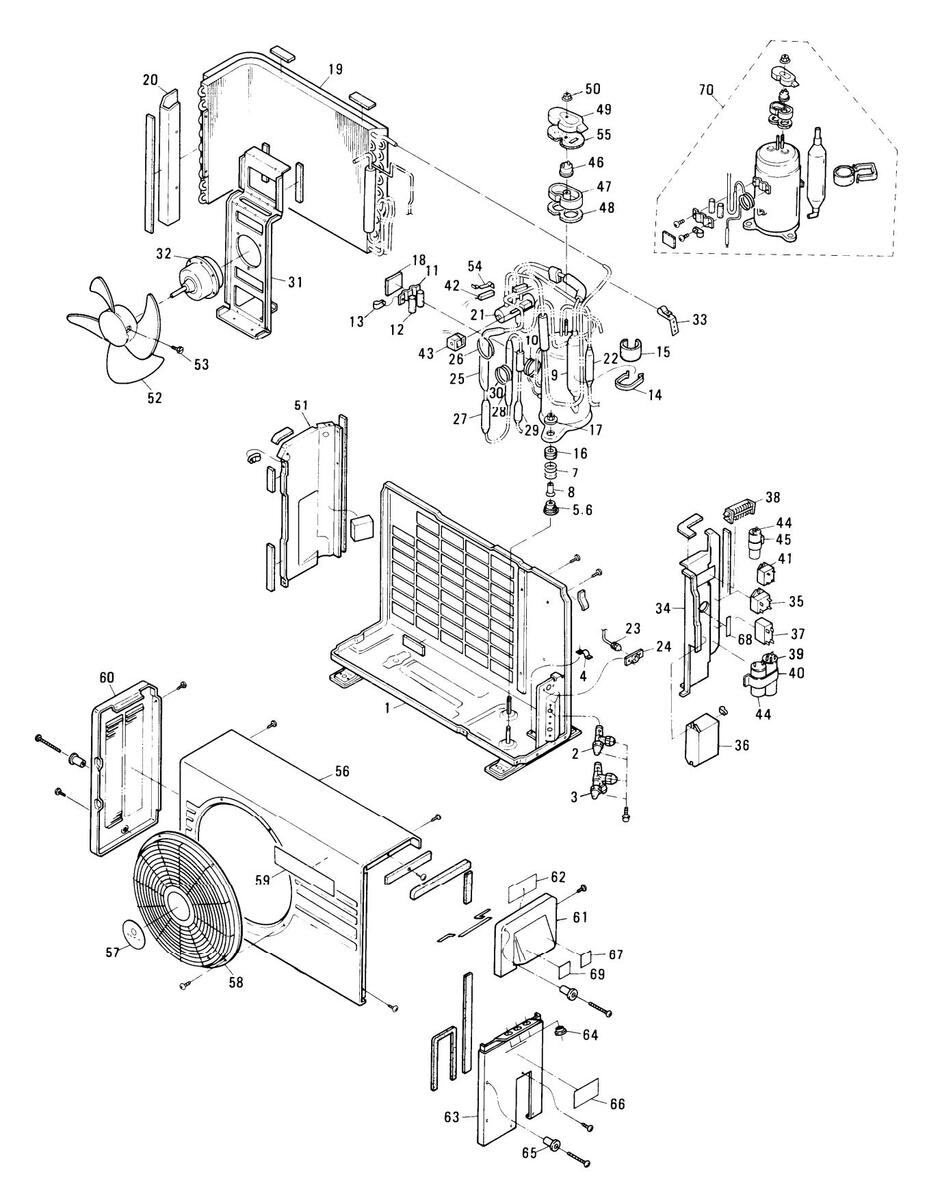
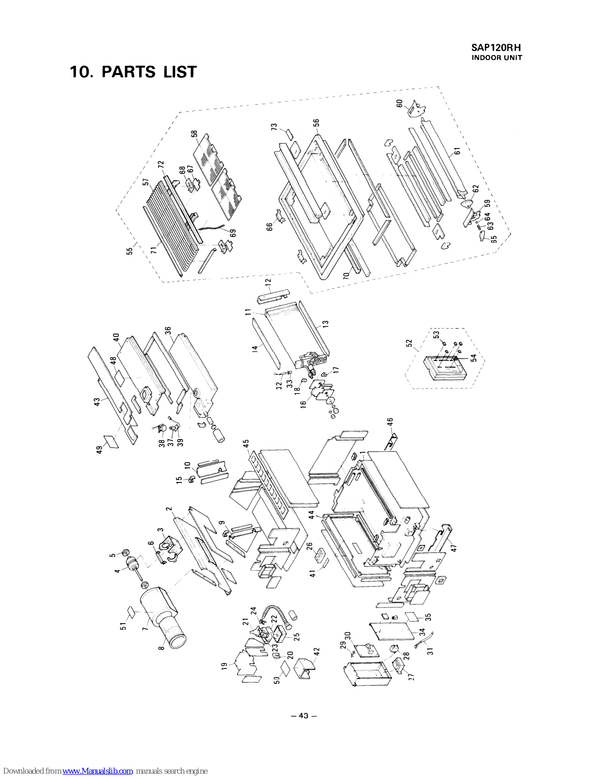
10. PARTS LIST

ATTENTION ! To ensure correct parts supply, please let us know followings, when you make service parts order: 1.Part No. 2.Description 3.O'ty 4.Volts-Hz-Ph 5.Product Model No.
| Key | Dart No | Deceription | 0 ' + |
|---|---|---|---|
| 1 | 854-0-1104-142H1 | Cabinet Acc'y | |
| 2 | 854-0-2516-13081 | Partition Plate Acc'u | |
| 3 | 854-0-2511-17401 | Support Motor Ace'v | |
| 851-0-5291-265M1 | Fan Motor Acc'v VEU60-21A1D | ||
| 852-2-2511-12020 | Cuchion Pubbor Fon Motor | ||
| 854-2-2518-312020 | Mounting Disto | ||
| 854-0-2502-20801 | Fan Casing Ace'y | ||
| 8 | 854-0-2501-14700 | Centrifugel Fen Acc'y | |
| 854-2-2303-21042 | Mounting Diato Acc'y Evaporator | ||
| 854-2-2303-224 #1 | Mounting Plate Ass y, Evaporator | 1 | |
| 854-0-4118-50901 | Evaporator Ass'v (incl No 12) | ||
| 12 | 854-2-2303-22301 | Mounting Plate, Evaporator | 1 |
| 13 | 854-2-2404-19501 | Insulation, Evaporator | |
| 14 | 854-2-2404-19601 | Insulation. Evaporator | 1 |
| 15 | 854-2-2303-21800 | Mounting Plate, Evaporator | 2 |
| 16 | 854-2-1133-214H2 | Cover Plate Ass'y | 1 |
| 17 | 854-2-2360-15300 | Mounting Plate | 1 |
| 18 | 854-2-2360-45100 | Mounting Plate | 1 |
| 19 | 854-2-2307-125H1 | Cover Plate Ass'y, Fan Motor | 1 |
| 20 | 854-2-2338-15300 | Eyelet Rubber | 1 |
| 21 | 851-0-5291-265P1 | Pump Ass'y WP20SL-4 | 1 |
| 22 | 854-2-2360-44400 | Mounting Plate | 1 |
| 23 | 854-2-2360-44300 | Mounting Plate | 1 |
| 24 | 854-2-2315-10301 | Clip | 1 |
| 25 | 854-2-5312-57601 | Mounting Plate | 1 |
| 26 | 4-2379-56170 | Terminal Base JTU20-6 | 1 |
| 27 | 851-0-5291-265P2 | Transformer Ass'y ATR-J121U1 | 1 |
| 28 | 4-2239-51171 | Fixed Capacitor 220V 8MFD | 1 |
| 29 | 851-2-5366-01400 | Spacer | 6 |
| 30 | 851-0-5158-40700 | Controller Ass y PUW-120KH | 1 |
| 31 | 851-0-5291-26511 | Thermistor Ass y | 1 |
| 32 | 851-0-5291-26512 | Inermistor Ass y NIC-51H-54 | |
| 33 | 852-2-5304-13700 | Ulip, Inermistor | |
| 34 | 854-2-5304-31001 | Cover Plate | |
| 26 | 954-0-2201-24001 | 1 | |
| 27 | 004-0-2001-049H1 | ||
| 20 |
001-0-0291-20051
854-2-2346-12010 |
SWILLI ASS Y FS-30020-201 | |
| 20 | 854-2-2360-40201 | Mounting Dlato | |
| 10 | 851-0-2325-17102 | 1 | |
| 41 | 852-6-4729-173001 | + | | |
| 42 | 854-2-5305-12101 | Cover Terminal | |
| 43 | 854-2-5304-278H21 | Cover Plate Ass'v | + |
| 44 | 854-0-1109-213H1 | Rear Panel Ass'y | |
| 45 | 854-2-1110-16101 | Blade Louver | |
| 46 | 854-2-1130-14401 | Hook Plate | |
| 47 | 854-2-1130-14501 | Hook Plate | |
| 48 | 854-6-4729-75700 | Label | 1 |
| 49 | 854-6-4729-71600 | Label | 1 |
| 50 | 852-6-4419-22000 | Label | 1 |
NOTE: Metal and plastic parts will be supplied basically with necessary heat insulation pads or packing.
ATTENTION ! To ensure correct parts supply, please let us know followings, when you make service parts order: 1. Part No. 2. Description 3. Q'ty 4. Volts-Hz-Ph 5. Product Model No.
|
Key
No: |
Part No. | Description | Q'ty |
|---|---|---|---|
| 51 | 854-2-1367-70800 | Name Plate | 1 |
| 52 | 851-0-0051-25200 | Remote Control Unit Ass'y RCS-120RH | 1 |
| 53 | 851-2-5375-01603 | Knob | 6 |
| 54 | 851-2-5375-05001 | Knob | 1 |
| 55 | 859-341-57 | Panel Ass'y SAP-120RW | 1 |
| 56 | 854-2-1112-21520 | Top Panel | 1 |
| 57 | 854-0-1110-13701 | Air Intake Grille Ass'y | 1 |
| 58 | 854-0-1302-14220 | Air Filter Ass'y | 2 |
| 59 | 854-2-1114-10910 | Cap, Top Panel | 1 |
| 60 | 854-2-1323-11310 | Lamp Cover | 1 |
| 61 | 854-0-1505-23501 | Blade Louver Ass'y | 1 |
| 62 | 854-2-1111-19810 | Support Louver | 1 |
| 63 | 854-2-1341-10700 | Coil Spring | 1 |
| 64 | 854-2-4541-10201 | Ball Steel | 1 |
| 65 | 854-2-1129-47701 | Mounting Plate | 1 |
| 66 | 854-0-2312-10201 | Hinge Ass'y | 2 |
| 67 | 854-2-1129-47101 | Mounting Plate | 2 |
| 68 | 854-2-1130-14310 | Hook Plate | 2 |
| 69 | 854-0-1111-15100 | Mounting Parts Ass'y | 1 |
| 70 | 854-2-1309-12901 | Mounting Plate | 1 |
| 71 | 854-2-1123-13101 | Mounting Plate, Grille | 1 |
| 72 | 854-2-1123-13201 | Mounting Plate, Grille | 1 |
| 73 | 854-2-1354-17601 | Badge | 1 |
| ٠ | 854-6-4139-50500 | Installation Instructions | 1 |
| ٠ | 854-6-4119-47400 | Operation Manual | 1 |
NOTE: Metal and plastic parts will be supplied basically with necessary heat insulation pads or packing.
Accessory Parts List
| Description | Shape | Ω΄ιγ | Remarks | Description | Shape | ary | Remarks |
|---|---|---|---|---|---|---|---|
| PVC pipe | 1 | 854-2-2334-13600 | Flanged hex nut | Ð | 4 | 851-0-2395-10201 | |
| Gauge | 1 | 854-6-4139-40900 |
Suspension
lugs |
Ceres Ceres |
1
Fach |
854-2-1130-14401
854-2-1130-14501 |
|
|
Insulation
material |
1 | 854-2-2410-41710 | |||||
| Clamper | 2 | 800-2-5308-11200 | Remote | ||||
|
Insulation
tape |
3 |
854-2-1351-75710×1
854-2-2336-65910×2 |
unit | 851-0-0051-25200 | |||
| Pan-head screw | M5 | 4 | 3-9231-54003 | q·p | |||
|
Countersunk-head
wood screw |
D | 2 | 3-9261-21301 | Mounting plate | D | 851-2-5378-01001 | |
|
Drain Hose
adaptor |
1 | 854-2-2334-14100 | es | ||||
|
Lead wire for
remote control unit |
1 | 851-0-5290-30700 |
- 46 -
PARTS LIST

ATTENTION ! To ensure correct parts supply, please let us know followings,
when you make service parts order: 1. Part No. 2. Description 3. Q'ty 4. Volts-Hz-Ph 5. Product Model No.
|
Key
No. |
Part No. | Description | Q'tv |
|---|---|---|---|
| 1 | 852-0-2202-26001 | Bottom Plate Ass'v | 1 |
| 2 | 852-0-4501-26600 | Valve Ass'y 1/4 in. | 1 |
| 3 | 852-0-4501-21800 | Valve Ass'v 1/2 in. | |
| 4 | 852-2-2362-15701 | Mounting, Tube | |
| 5 | 851-2-2390-13700 | Cushion Rubber | |
| 6 | 851-2-2390-13100 | Cushion Rubber | 2 |
| 7 | 851-2-2330-13001 | Spring | 3 |
| 8 | 851-2-1314-17301 | Stopper | 3 |
| 9 | 852-0-4511-14500 | Accumulator Ass'y | 1 |
| 10 | 852-0-4202-57000 | Tube Ass'y, Capillary | 1 |
| 11 | 852-2-2309-34101 | Mounting Plate | 1 |
| 12 | 852-2-2353-19500 | Packing | 2 |
| 13 | 3-9030-00506 | Clamper F-4 | 1 |
| 14 | 852-2-2356-14601 | Band Mounting | 1 |
| 15 | 852-2-2353-38310 | Packing | 1 |
| 16 | 851-2-2390-13600 | Cushion Rubber | 3 |
| 17 | 851-0-2395-10501 | Nut Special Ass'y | 3 |
| 18 | 852-2-2353-19810 | Packing | 1 |
| 19 | 852-0-4102-33300 | Condenser Ass'y (incl.No.20) | 1 |
| 20 | 852-2-2351-141H1 | Cover Plate Ass'y | 1 |
| 21 | 4-2649-56162 | Reversing Valve V26-9000 | 1 |
| 22 | 852-2-4501-11600 | Muffler | 1 |
| 23 | 852-0-4507-33800 | Nipple Ass'y | 1 |
| 24 | 852-2-2309-19909 | Mounting Plate | 1 |
| 25 | 852-0-4204-12500 | Check Valve Ass'y | 1 |
| 26 | 852-2-4219-56300 | Capillary Tube | 1 |
| 27 | 852-0-4505-14600 | Dehydrater Ass'y | 1 |
| 28 | 854-0-4518-13800 | Check Valve Ass'y | 1 |
| 29 | 852-0-4506-15900 | Strainer Ass'y | 1 |
| 30 | 852-2-4219-56400 | Capillary Tube | 1 |
| 31 | 852-2-2354-140H2 | Mounting Plate Ass'y, Fan Motor | 1 |
| 32 | 851-0-5291-436M1 | Fan Motor Ass'y FT6-21C1PE | 1 |
| 33 | 852-2-2362-15601 | Mounting, Tube | 1 |
| 34 | 852-2-5307-304H1 | Elec. Component Box Ass'y | 1 |
| 35 | 4-2329-56282 | Relay DFU24D1-F(M) | 1 |
| 36 | 859-472-58 | Controller POW-90CH | 1 |
| 37 | 4-2239-51171 | Fixed Capacitor 220V 8MFD | 1 |
| 38 | 4-2379-56171 | Terminal Base JTU20-8 | 1 |
| 39 | 4-2239-56281 | Fixed Capacitor 330V 35MFD | 1 |
| 40 | 852-2-5301-22801 | Clip, Capacitor | 1 |
| 41 | 4-2329-69210 | Relay AMVL-180A | 1 |
| 42 | 4-2339-56186 | Thermostat TRS-12M160UL | 1 |
| 43 | 4-2649-56161 | Solenoid L27-9069 | 1 |
| 44 | 4-2239-60210 | Fixed Capacitor 160V 100MFD | 2 |
| 45 | 852-2-5301-17100 | Clip, Capacitor | 1 |
| 46 | 4-2329-69092 | Relay MRA98693-9200 | 1 |
| 47 | 801-2-6194-12200 | Cover Terminal | 1 |
| 48 | 801-2-5303-12100 | Gasket Terminal | 1 |
| 49 | 801-2-6195-10500 | Cap lerminal Cover | 1 |
| 50 | 819-2-6919-10100 | Nut, Compressor | 1 |
NOTE: Metal and plastic parts will be supplied basically with necessary heat insulation pads or packing.
ATTENTION ! To ensure correct parts supply, please let us know followings, when you make service parts order: 1. Part No. 2. Description 3. O'ty 4. Volts-Hz-Ph 5. Product Model No.
|
Key
No. |
Part No. | Description | Q'ty |
|---|---|---|---|
| 51 | 852-2-2202-173H7 | Partition Plate Ass'y | 1 |
| 52 | 852-0-2502-12611 | Propeller Fan Ass'y (incl.No.53) | 1 |
| 53 | 852-2-2510-10202 | Bolt Special | 1 |
| 54 | 852-2-5303-12100 | Mounting Thermostat | 1 |
| 55 | 801-2-5321-10600 | Cover Gasket | 1 |
| 56 | 852-2-1112-150D3 | Cabinet Ass'y | 1 |
| 57 | 852-2-1316-26201 | Mark | 1 |
| 58 | 852-0-1111-13001 | Guard Ass'y | 1 |
| 59 | 852-2-1316-26102 | Mark | 1 |
| 60 | 852-0-1104-14912 | Side Panel Ass'y | 1 |
| 61 | 852-0-1104-159H2 | Side Panel Ass'y | 1 |
| 62 | 851-2-5251-53001 | Elec. Wiring Diagram | 1 |
| 63 | 852-0-1104-160H1 | Side Panel Ass'y | 1 |
| 64 | 851-2-5370-01400 | Bushing | 3 |
| 65 | 852-2-2326-14302 | Spacer | 3 |
| 66 | 852-2-1335-85900 | Name Plate | 1 |
| 67 | 854-6-4729-71600 | Label | 1 |
| 68 | 852-6-4729-17300 | Label | 1 |
| 69 | 852-6-4419-22000 | Label | 1 |
| 70 | 852-0-4516-13100 | Compressor Ass'y C-R90H2S | 1 |
NOTE: Metal and plastic parts will be supplied basically with necessary heat insulation pads or packing.
11. REFRIGERANT FLOW DIAGRAMS
COOLING CYCLE

NOTE :
- → with sequential number in circle shows flow of refrigerant in COOLING CYCLE.
- with sequential number in circle shows flow of refrigerant in HEATING (= Reverse) CYCLE.
HEATING CYCLE

12. ELECTRIC WIRING DIAGRAMS


SAP120CH ELECTRIC WIRING DIAGRAM
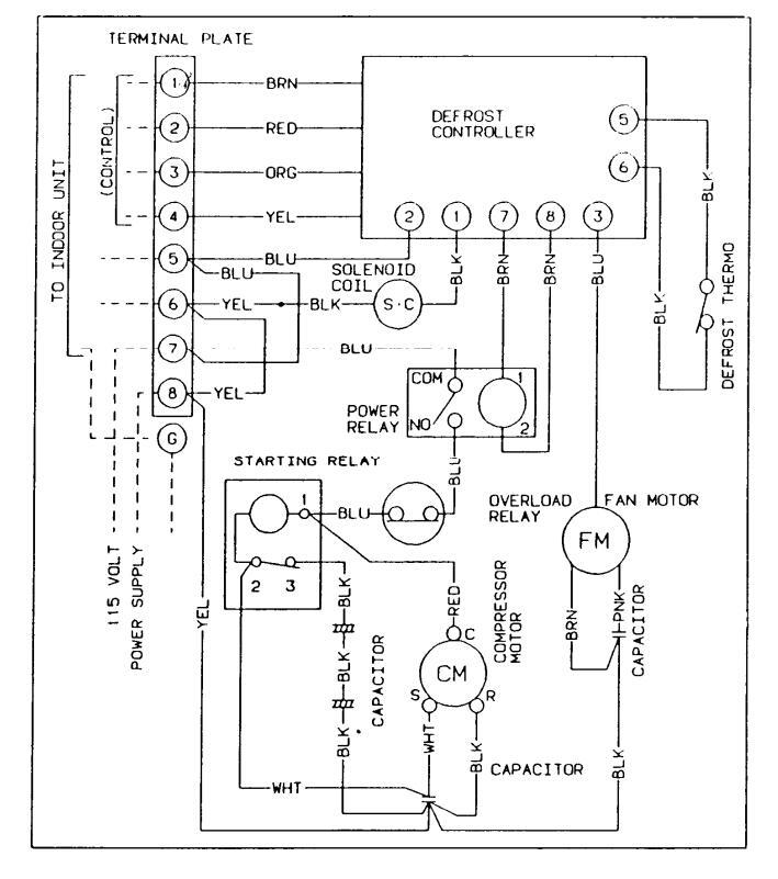
- 50 -
CONTROLLER P.C.B. (PRINTED PATTERN)
POW-120RH (for SAP120RH)

ELECTRIC WIRING DIAGRAM (CONTROLLER P.C.B.) POW-120RH (for SAP120RH)


Downloaded from www.Manualslib.com manuals search engine


 Loading...