

Sanyo SANUPS A11J Instruction Manual
M0009237
5 kVA
Instruction Manual
Introduction
Thank you for choosing the SANUPS A11J.
SAVE THESE INSTRUCTIONS
This manual contains important instructions for A11J that should be followed during installation and
maintenance of the UPS*1 and batteries to protect the safety of the customer and the service
technician*2. To use the UPS correctly and safely, read this manual before using the UPS. For details on
the functions and operation of the LCD panel, see the separate
LCD Panel Operating Manual
. After
reading, please keep this manual handy for convenient reference together with the
LCD Panel
Operating Manual
.
This UPS is intended for installation in a temperature-controlled indoor environment free of conductive
contaminants.
Operating temperature: 0 to 40 C (32 to 104 F)
*1
UPS is an abbreviation for Uninterruptible Power Supply.
Table of Contents
§1. Before Use ............................................................................................................... 1
§2. Safety Precautions .................................................................................................. 2
§3. For Proper Operation.............................................................................................. 6
§3.1 UPS Input Power Supply............................................................................... 6
§3.2 Installation Precautions ............................................................................... 6
§3.3 Usage Precautions ........................................................................................ 7
§4. Checking Contents of Package ............................................................................... 8
§5. External Dimensions and Part Names .................................................................. 9
§5.1 UPS................................................................................................................. 9
§5.2 LCD Panel .................................................................................................. 10
§5.3 Unit Control Panel......................................................................................... 11
§5.4 External Interfaces ...................................................................................... 12
§6. Installation and Wiring........................................................................................... 15
§6.1 Installation..................................................................................................... 15
§6.1.1 Checking Installation Environment ................................................... 15
§6.1.2 Checking Installation Space................................................................ 15
§6.1.3 Installing UPS Horizontally................................................................ 16
§6.1.4 Installing UPS Vertically..................................................................... 16
§6.2 Attaching LCD Panel..................................................................................... 17
§6.3 Wiring ............................................................................................................. 19
§6.4 Connecting Optional Equipment................................................................... 21
§7. Preparation Before Operation ................................................................................ 23
§7.1 Checking UPS Settings.................................................................................. 23
§7.2 Charging UPS ................................................................................................ 24
§7.3 Power Outage Simulation Test...................................................................... 25
This term is used to indicate service technicians from SANYO DENKI or entrusted by SANYO
DENKI with knowledge of this UPS.
Maintenance work must not be performed by other than a qualified service technician.
*2 Service technician

Notes about UPS Models
This manual is for the UPS model authorized with UL standard shown in the following table.
Confirm your UPS model before using the UPS.
* In this instruction manual, the name of UPS is described as Model “A11J502U002T” depending on the item explained.
§8. Operating Procedures ............................................................................................. 27
§8.1 UPS Startup................................................................................................... 27
§8.2 UPS Shutdown ............................................................................................. 29
§8.3 Operation Using Unit Control Panel ............................................................ 30
§9. Inspection and Maintenance................................................................................... 31
§9.1 Routine Checks by Customer ........................................................................ 32
§9.2 Battery Test .................................................................................................... 33
§9.3 Resetting Main Breaker ................................................................................ 33
§10. Buzzer Sounds....................................................................................................... 34
§11. Troubleshooting..................................................................................................... 35
§12. Using Power Management Software.................................................................... 39
§13. Using Operating System Standard UPS Service................................................. 41
§14. UPS Characteristics.............................................................................................. 43
§14.1 Basic Operation............................................................................................ 43
§14.2 Protective Functions .................................................................................. 44
§14.3 Protective Function Table............................................................................ 44
§14.4 Specifications................................................................................................ 45
§15. Warranty................................................................................................................ 46
Capacity
Type Model*
5 kVA A11J502A002TU A11J502U002T
Before Use
1
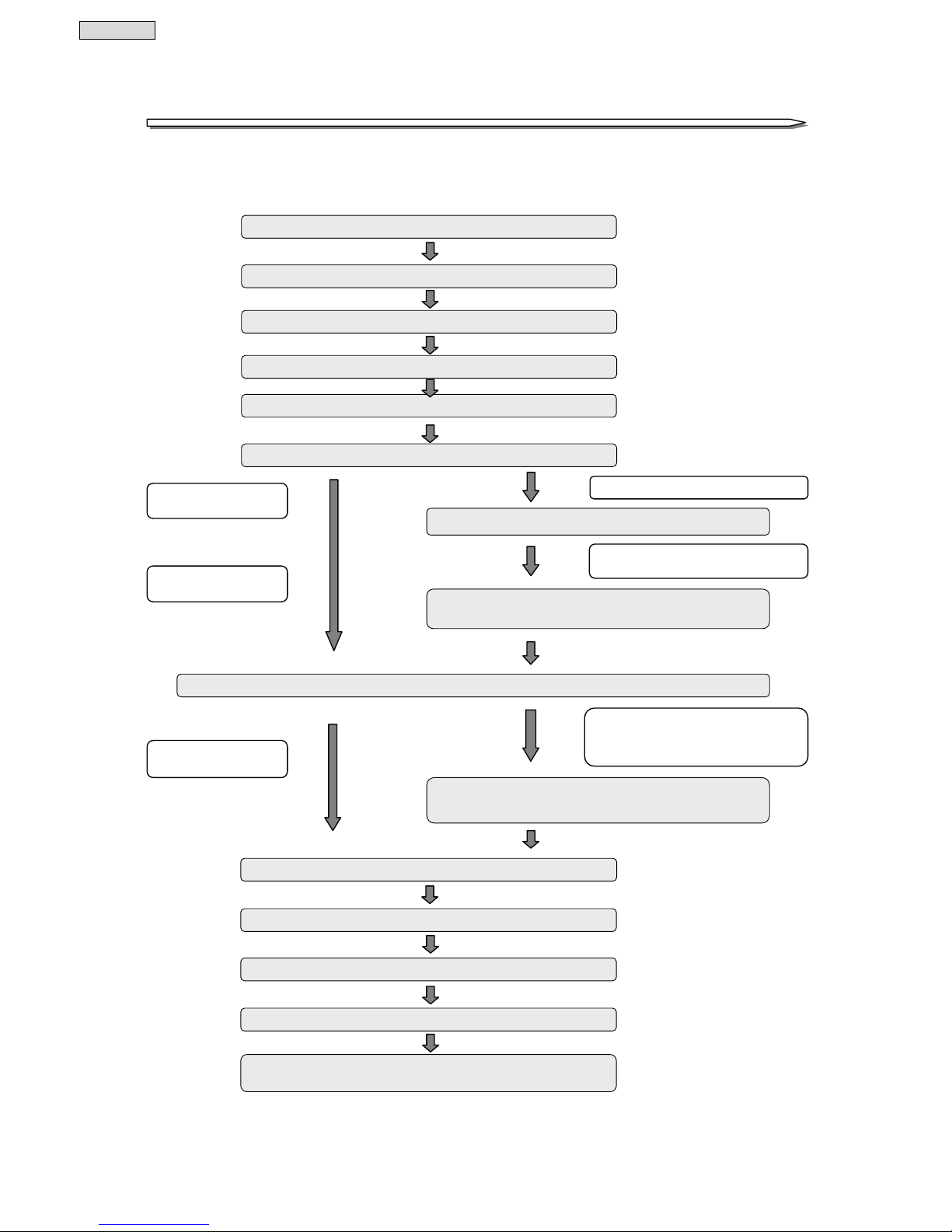
§11.. BBeeffoorree UUssee
The following shows the procedures to use the UPS. Be sure to follow the procedures described in this
instruction manual to ensure safe and proper use of the UPS.
Check the safety precautions ⇒ pages 2 to 5
Check the operating precautions ⇒ pages 6 to 7
Check the contents of the package ⇒ page 8
Install the UPS ⇒ pages 15 to 16
Attach the LCD panel ⇒ pages 17 to 18
When using power management software
for power management of the UPS
Install the power management software on the computer,
and connect the cables
⇒
pages 39 to 40
Check the default values of the LCD panel setting menu ⇒ page 23, LCD Panel Operating Manual
When the default settings of the LCD panel
setting menu do not match, for example, the
environment, intended use, or load
specifications, change the settings.
Change the setting values of the setting menu
⇒
LCD Panel Operating Manual
Start the UPS ⇒ page 27
When not using power
management software
When the setting menu does
not need to be changed
Charge the UPS ⇒ page 24
Customer performs routine checks ⇒ page 32
Submit request for repairs when trouble,
replacement of batteries, etc.
⇒
page 31
Perform the power outage simulation test
⇒
pages 25 to 26
Wire the UPS ⇒ pages 19 to 20
Connect the optional equipment
⇒
page 21
When using optional equipment
When not using optional
equipment
Safety Precautions
2
§22.. SSaaffeettyy PPrreeccaauuttiioonnss
PRECAUTIONS
(IMPORTANT SAFERY INSTCUTIONS)
This manual contains important instructions for operating and maintaining the A11J Series and the batteries
to protect the safety of the customers and the service technician.
Before installing, operating, performing maintenance or inspecting the UPS, be sure to read this manual and
accompanying documents carefully to obtain a clear understanding of the information related to its operation,
safety and important precautions.
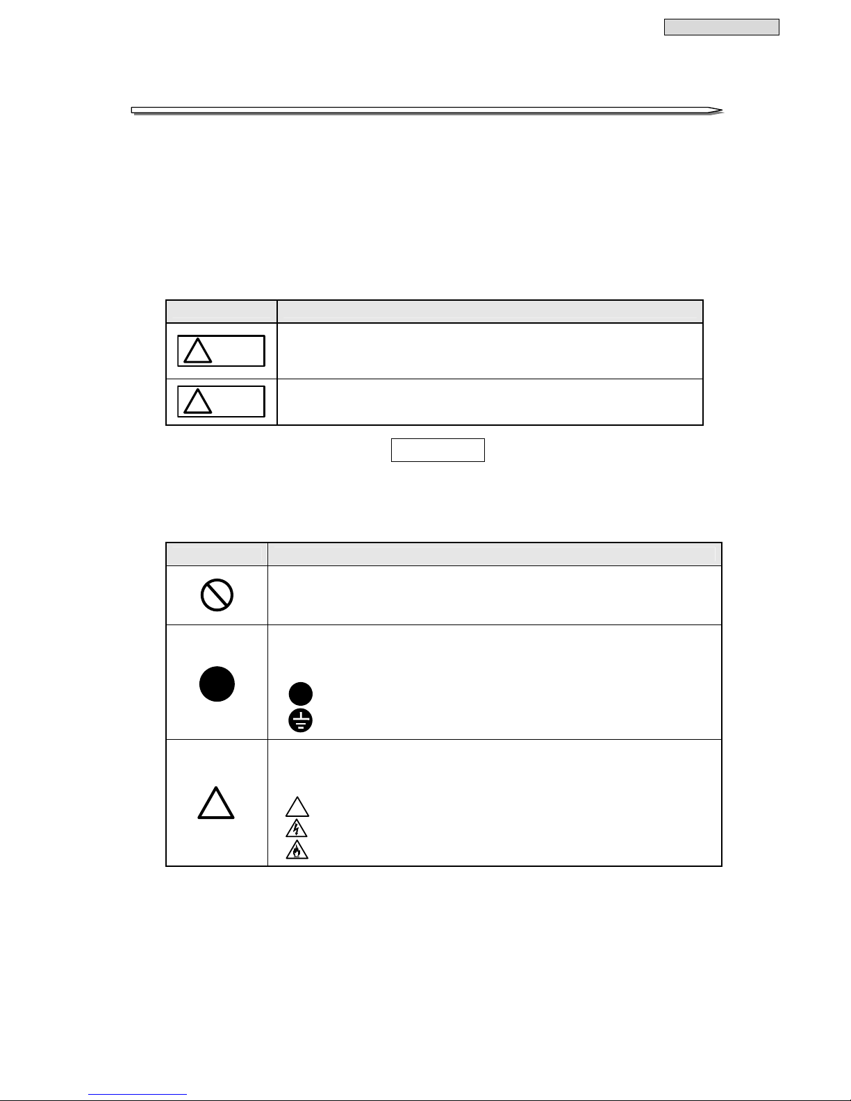
This manual uses two safety warning levels, WARNING and CAUTION, as described below.
Label Explanation
WARNING
!
Denotes immediate hazards which WILL probably cause severe bodily
injury or death, as a result of incorrect operation.
CAUTION
!
Denotes hazards which COULD cause bodily injury and product or property
damage, as a result of incorrect operation.
Additionally, even those hazards denoted by
△
!
CAUTION
could lead to a serious accident, so the
instructions should be strictly followed.
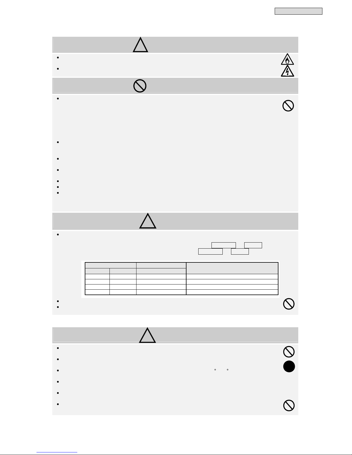
The following labels indicate particularly important instructions which must be carefully followed. The
graphic symbols indicate prohibited and mandatory actions.
Symbol Explanation
Indicates actions that must not be allowed to occur (prohibited actions).
Indicates actions that must be taken (mandatory actions).
Specific information appears within the graphic symbol or in an explanation
nearby.
!
: This example signifies the mandatory actions.
: This example signifies that the equipment must be securely grounded.
Indicates CAUTION (including WAR NI NG ).
Specific information appears within the graphic symbol or in an explanation
nearby.
!
: This example signifies the general caution.
: This example signifies that there is danger of electric shock.
: This example signifies that there is danger of a fire or smoke generation.
Safety Precautions
3
1. Relocation, Transportation and Moving Precautions
CAUTION
Be careful to avoid falling or dropping the UPS during relocation, transportation, as bodily injury could result.
Be careful to avoid back strain when handling the UPS.
To avoid bodily injury or a malfunction caused by dropping the UPS, do not tilt the UPS more than 10 degrees to either
side when moving it vertically. Take preventative measures to avoid dropping the UPS if it must be tilted more than
10 degrees when moving it.
2. Installation Precautions
CAUTION
The UPS should be installed only by technically qualified personnel.
Improper installation may result in electric shock, bodily injury, and/or fire.
Never operate or store the UPS in the following environmental conditions.
Doing so may cause the UPS to malfunction, sustain damage or deteriorate, which could result in a fire or
other accidents.
a. In ambient environmental conditions other than those specified in the product brochure and
instruction manual (temperature 0 to 40°C (32 to 104°F), relative humidity 20 to 90%), such as in
extremely high or low temperature and high humidity.
b. Where the UPS is exposed to direct sunlight.
c. Where the UPS is directly exposed to the heat from a heat source, such as a stove.
d. Where the UPS may be subject to vibration or physical shock.
e. Near a device that may emit sparks.
f. In the presence of dust, salt or corrosive or flammable gas.
g. Outdoors
Be careful not to block the air intake and exhaust vents of the UPS. Keep the front of the UPS at least 20 cm
(8 inches) and the back of the UPS at least 15 cm (6 inches) away from a wall or other object. If you mount
the UPS in a rack, mount it in a rack that can be well ventilated, and be careful not to block the air intake
and exhaust vents of the rack and UPS. If the air intake or exhaust vent is blocked, the internal
temperature of the UPS rises, which could cause battery deterioration resulting in a fire. For maintenance,
the UPS requires at least 1 m (40 inches) of space at the front, and at least 50 cm (20 inches) at the back.
The space around the UPS must be ventilated. The required ventilation airflow is 7 m3/h. Unless the
specified ventilation airflow is maintained, gas produced by battery charging could result in rupture or
explosion of the case.
Install the UPS on a stable surface or rack capable of bearing the weight of the UPS in the correct manner
specified in this manual. Refer to the table in §5.1 for the weight of the UPS. If the UPS is installed
incorrectly, impact or vibration could cause it to fall or move inadvertently, resulting in bodily injury. Be
careful to avoid back strain when handling the UPS.
Move packaging such as plastic bags and film and accessories such as screws to a place that is out of reach
of children. If a child, for example, places film over his or her head or swallows a screw, there is danger of
suffocation.
3. Wiring Precautions
CAUTION
Wiring should be performed only by technically qualified personnel.
Incorrect wiring may result in electric shock and/or fire.
Protection for primary circuits against over currents, short circuits and ground faults is not provided inside
this UPS.
Protection in primary circuit against over currents, short circuits and earth faults shall be provided as part
of the building installation.
Connect the grounding cable securely in the manner specified (input/output terminal block).
This UPS requires class D grounding work. Failure to connect the grounding cable in accordance with the
specified grounding class may result in electric shock.
Have a qualified electrician perform any grounding work that may be required (a fee will be charged).
The grounding cables of all load devices* connected to the output of the UPS must be securely connected to
the grounding terminals. Failure to connect the grounding cables of the load devices correctly may result in
electric shock.
* Load devices are devices such as computers that are connected to the UPS.
!
!
!
!
!
!
!
Safety Precautions
4
4. Operating Precautions
WARNING
Immediately shut down the UPS if it malfunctions, or if an unusual odor or noise is observed.
Failure to do so may result in a fire.
To avoid electric shock, do not open the cover of the UPS. Do not detach the cover of the options, except when
you use some options. There is danger of electric shock or other accidents.
PROHIBITED
Never use the UPS for the following types of loads :
a. Medical instruments used for life support.
b. Control units for trains or elevators, failure of which may cause bodily injury.
c. Computer systems upon which social or public infrastructure depends.
d. Devices which serve applications related to the above.
Contact your sales representative if you need to use the UPS in an application like the above. Special equipment such
as redundant devices or an emergency generator must be incorporated when operating, maintaining and controlling
systems in which a UPS is used with loads affecting life-support or public infrastructure-dependent applications.
This UPS must be installed, operated and maintained by technically qualified personnel in an industrial
environment. This UPS should not be used in any other environment; for example, a general home environment
where a technically qualified personnel is not in.
Do not smoke or use an open flame near the UPS, as it could cause the UPS to explode or rupture, resulting in injury
or fire.
Do not place containers of liquid, such as a flower vase, on the UPS. If the container was to spill, the liquid could
cause a short circuit, resulting in sparks or fire inside the UPS.
Do not sit, ride, step or lean on the UPS, as bodily injury could result if the UPS was to fall.
Do not operate the switches with wet hands. There is danger of electric shock.
All repairs and modifications to the UPS are prohibited. The UPS contains high voltage and no user serviceable parts.
Opening the cover, exchanging the battery, parts exchange, and repair can result in electric shock or other accidents
when performed by anyone other than qualified service personnel. All such repairs and modifications will void the
warranty.
CAUTION
Check the load-side safety before starting the UPS, and operate the UPS in accordance with the instructions
in the manual.
The following table shows the UPS states resulting from operation of the
MAIN MCCB
or
ON/OFF
button.
Check the indicators before and after operating. Do not touch the
MAIN MCCB
or
ON/OFF
button unless
necessary. If power is supplied incorrectly, electric shock or bodily injury could result.
Avoid inserting sharp objects or fingers into the fan. Doing so may result in bodily injury.
Do not touch the UPS, including the cables, if you hear thunder nearby. There is danger of electric shock from
a lightning strike.
5. Maintenance and Inspection Precautions
CAUTION
Maintenance and repair of the inside of the UPS should be performed only by technically qualified personnel.
Electric shock, bodily injury, burns, fuming, or fire may otherwise result.
Contact your nearest sales representative or authorized service center to have the UPS checked out or to
replace defective parts. Opening the cover carelessly can result in an electric shock or burn.
Replace the batteries periodically (once every 4.5 years when operated at 25 C (77 F)). Using batteries after
their service life has expired may cause a fire.
Never use organic solvents such as gasoline, thinner, benzene or detergents to clean batteries. These can
cause the casing to crack and leak, resulting in electric leakage or fire.
Do not allow metal objects or fingers to touch the battery connectors of the UPS. Doing so may result in an
electric shock or burn.
Do not touch any parts inside the UPS, even when the AC input is removed and the batteries are removed.
There is the danger of electric shock from high voltage that remains in parts.
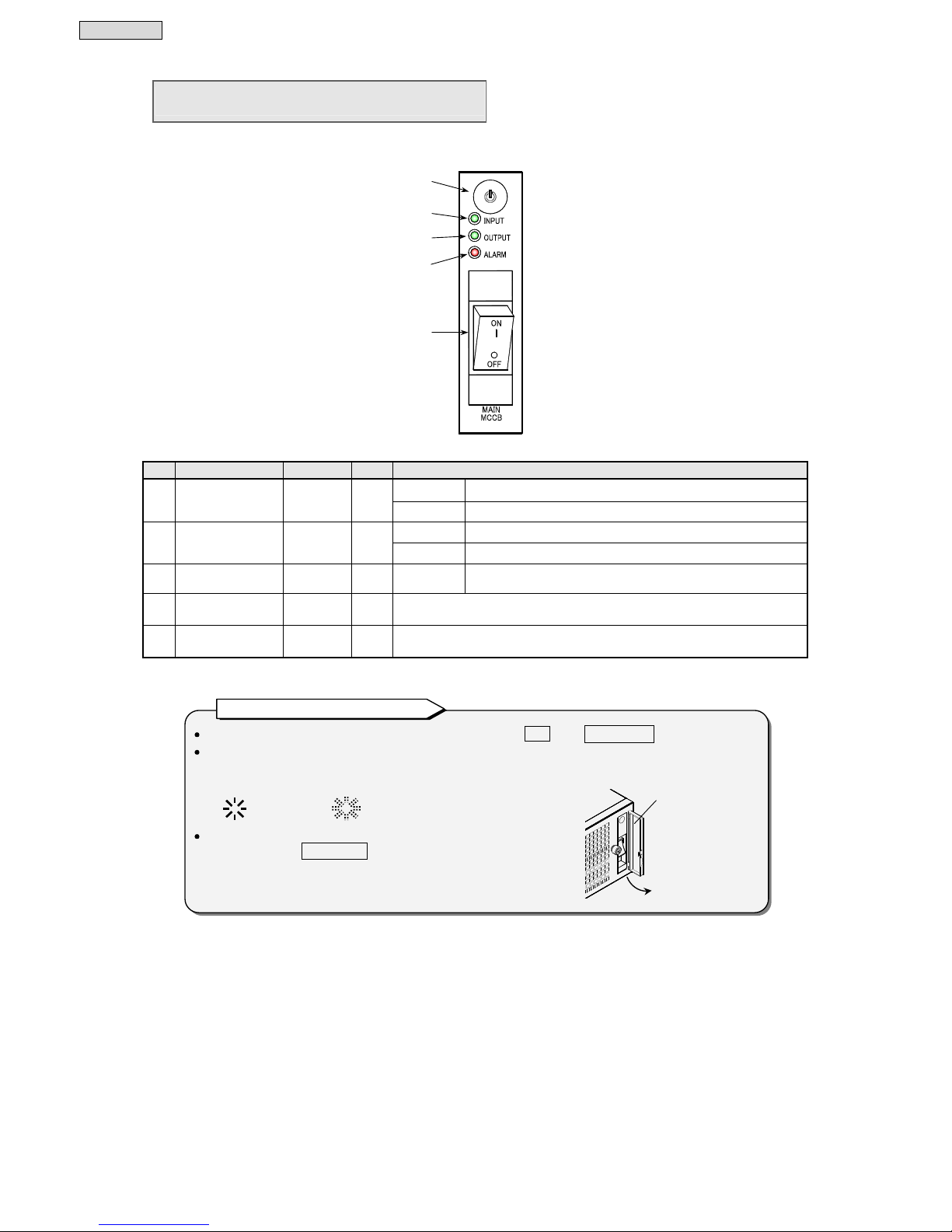
UPS Status
Output Status
MAIN MCCB ON/OFF
OUTPUT
LEDs
OFF OFF Stopped INPUT (off-green), OUTPUT (off-green)
ON OFF Stopped INPUT (on-green), OUTPUT (off-green)
OFF ON Output from inverter INPUT (blinking-green), OUTPUT (lit-green)
ON ON Output from inverter INPUT (lit-green), OUTPUT (lit-green)
!
!
!
!
Safety Precautions
5
6. Radio Frequency Interference
CAUTION
This equipment has been tested and found to comply with the limits for a Class A digital device, pursuant to part 15 of the
FCC Rules. These limits are designed to provide reasonable protection against harmful interference when the equipment is
operated in a commercial environment. This equipment generates, uses, and can radiate radio frequency energy and if not
installed and used in accordance with the instruction manual, may cause harmful interference to radio communications.
Operation of this equipment in the residential area is likely to cause harmful interference in which case the user will be
required to correct the interference at his own expense.
7. Battery Handling Precautions
CAUTION
Battery servicing should be performed by technically qualified personnel. Keep unqualified personnel away from
batteries.
Replace batteries only with the same model and brand as the ones used for this UPS. Risk of explosion if battery is
replaced by an incorrect type.
The batteries in this product are lead type batteries which are a reusable resource. Please cooperate by recycling when
replacing or disposing of used batteries. Dispose of used batteries according to the instructions. Customers should not
dispose of used batteries themselves. To dispose of used batteries, contact your nearest sales representative, an
authorized industrial waste handling company, or repack them in their original cartons and send them to your
supplier or SANYO DENKI.
Do not use batteries after their service life has expired. Doing so may result in fuming or fire. Additionally, the battery
backup function may fail to operate with such batteries, so that power will not be supplied to the load when a power
outage occurs.
Batteries pose hazards for electrical shock and dangerous short-circuit current. The following precautions
should be observed when working with batteries.
a. Remove watches, rings and other metal objects.
b. Use insulated tools.
c. Wear rubber gloves and boots.
d. Do not lay tools or metal parts on top of batteries.
e. Disconnect the charging source prior to connecting or disconnecting battery terminals.
f. Determine whether the batteries have been inadvertently grounded, and if so, remove the source of grounding.
Contact with any part of a grounded battery can result in electric shock.
Do not attempt to open or disassemble batteries. The electrolyte is harmful to the skin and eyes. The battery contains
diluted sulfuric acid, which is extremely toxic. If a battery leaks, take appropriate measures to prevent any battery
fluid contacting your skin or clothing. Diluted sulfuric acid may cause blindness if it gets into the eye, may burn skin
upon contact. It is electrically conductive and corrosive. Observe the following procedures if electrolyte spills:
a. Wear full eye protection and protective clothing.
b. If sulfuric acid contacts the skin, wash it off immediately with water.
c. If sulfuric acid contacts the eyes, flush thoroughly and immediately with water, and seek medical attention.
d. Spilled sulfuric acid should be washed down with a suitable acid-neutralizing agent, such as a solution of
approximately one pound (500 grams) of bicarbonate of soda in one gallon (4 liters) of water. The bicarbonate of
soda solution should be applied until evidence of reaction (foaming) has ceased. The resulting liquid should be
flushed with water and the area dried.
Lead-acid batteries may present the risk of fire due to the generation of hydrogen gas. The following precautions
should be observed.
a. DO NOT SMOKE near batteries.
b. DO NOT allow flames or sparks near batteries.
c. Before working with batteries, discharge static electricity from the body by first touching a grounded metal
surface before touching the batteries.
If a fire occurs near a battery, do not use water to extinguish it. Use only a powder-extinguishing agent (ABC). Using
water may cause the fire to spread.
Do not dispose of batteries in fire, as they may explode.
Strictly observe the following precautions when handling the batteries. Failure to do so may cause battery leakage,
overheating or explosion.
a. Do not solder to any part of a battery directly.
b. Do not charge the batteries with reversed positive (+) and negative (-) terminal polarity.
c. Do not mix different battery types, brands or versions.
d. Do not attempt to peel off or break the outer covering of a battery.
e. Do not subject batteries to strong physical shock, or throw them away.
f. Clean batteries with water-moistened cloth squeezed hard. Do not use organic solutions such as gasoline,
thinner or benzene or detergent.
g. Electrical energy may remain in a battery even after its service life has expired. Do not allow sparks near used
batteries, and protect them from short-circuiting.
!
!
!
Operating Precautions
6
§33.. FFoorr PPrrooppeerr OOppeerraattiioonn
§33..11 UUPPSS IInnppuutt PPoowweerr SSuuppppllyy
(1) Input Power Supply and Power Supply Capacity
The following table shows the ratings for the AC input power of this UPS. For the voltage and frequency
variation ranges, see §14.4 “Specifications.”
Name AC Input Voltage Rating
AC Input
Frequency Rating
Input
Capacity
Input Branch
Circuit Breaker
Type A11J502A002TU
Model A11J502U002T
200, 208, 220, 230, 240V *
1
(
Factory
default
)
50 or 60 Hz *
2
5.5 kVA 35A *3
*1. When the UPS is shipped from the factory, this is set to 200 V. Change the setting to match the AC
voltage of the area in which the UPS is to be used from the setting menu of the LCD panel. For the
setting procedure, see the
LCD Panel Operating Manual
.
*2. When the UPS is shipped from the factory, it is set to automatically detect the AC input frequency (50
or 60 Hz).
*3. The input branch circuit breaker should be compliant with UL489 of the branch circuit protection.
(2) The UPS input should be connected to a single-wire grounded power supply, and the input N should be
connected to a ground line.
§33..22 IInnssttaallllaattiioonn PPrreeccaauuttiioonnss
(1) Carefully consider the leakage current when a leakage circuit
breaker is installed on the input side.
The maximum leakage current is 4 mA.
(2) Keep the UPS at least 1 m (40 inches) away from CRT displays.
Other devices which may be sensitive to magnetic flux should be
kept away from the UPS, as it emits a slight amount of magnetic
flux.
(3) The UPS employs a fan for forced-air cooling. Provide the clearances
specified in §6.1.2 “Checking Installation Space” to permit air to flow
freely at the air intake and exhaust vents.
(4) Be careful to connect the input poles of loads if the load requires single-wire grounded. Always
connect the ground phase to the N terminal of the UPS. For details, see §6.3 “Wiring.”
A
t least 1 m
Operating Precautions
7
§33..33 UUssaaggee PPrreeccaauuttiioonnss
(1) Never short-circuit the output circuits.
Doing so will cause the protective functions of the UPS to activate or the breaker to trip, preventing
output.
(2) Unsuitable load devices
Do not connect laser printers, plain paper fax machines, copy machines, overhead projectors, vacuum
cleaners or hair dryers to the UPS. Since such devices are subject to high transient current surges,
the UPS will detect current surges and the battery backup operation will become no longer possible
when a power outage occurs. There is also the danger of the UPS malfunctioning.
(3) Power supply environment
If the UPS is used in an environment subject to long and frequent power outages (more than once a
week), the batteries may not receive sufficient charge, which could result in foreshortened battery
life and premature battery failure.
(4) If the UPS is stored without being operated for a long period, the batteries may require recharging. If
the batteries in the UPS are left uncharged, their service life will be greatly foreshortened. Recharge
the batteries in accordance with the UPS storage environment as shown in the table below.
For the time required to recharge the batteries, see §7.2 “Charging UPS.”
Storage
Tem pe ra tu r
e
Recharge Interval
25 C (77 F)
Once every 6 months
30 C (86 F)
Once every 4 months
40 C (104 F)
Once every 2 months
(5) Insulation testing
Before testing the indoor wiring insulation, shut down the UPS and disconnect the input and output
cables.
Conducting an insulation test with the UPS connected may damage electronic components such as
the built-in arrester.
(6) The UPS can be mounted on a rack (L-shaped support rails are required). For the information of the
needed parts, how to install and more, contact your supplier or SANYO DENKI representative.
①
Set
MAIN MCCB
on the front panel of the UPS to “ON.”
②
Check that “Green INPUT” is lit.
Recharging starts.
③
Continue operation as is for specified time or longer.
④
After the specified time or longer elapses, set
MAIN MCCB
to
“OFF.”
Recharging procedure
Checking the Contents of the Package
8
If you sell the UPS or transfer ownership to a third party, transfer or sell all the accessories and other
items supplied with the UPS.
§44.. CChheecckkiinngg CCoonntteennttss ooff PPaacckkaaggee
After you open the package, check to make sure that it contains all of the following items.
Does it contain the UPS and all accessories?
Is the exterior of the UPS damaged or unusual?
Check and place a mark in □.
If any item is missing or unusual, contact your supplier or SANYO DENKI.
*1. Rack Mounting Brackets are used for installation on a rack. However the L-shaped support rails are required to install
on a rack. For the information of the needed parts how to install on a rack and more, contact your supplier or SANYO
DENKI representative.
□
A11J 1
□
Instruction Manual English 1
Japanese 1
□
Rack Mounting Bracket*
1
2
□
Communication Cable 1
□
Power Management
Software CD-ROM 1
Note on transferring or selling the UPS
□
Screw C: M3 x 6 2
For securing LCD panel
□
Screw B: M4 x 8 4
For attaching brackets
□
LCD Panel 1
□
LCD Panel Connection Cable 1
□
Floor Mounting Bracket 2
□
Support Bracket A:
For attaching floor mounting
brackets 4
□
Screw A:M4 x 6 (black) 6
For attaching brackets
□
Support Bracket B:
For attaching rack mounting
brackets*
1
2
This is an image. The actual shapes of the UPS and accessories may differ.
□
Label for Battery
Replacement 1
□
Name Plate Usage
Procedure Manual
English 1
Japanese 1
□
Screw D:M4 x 10 4
For terminal block cover
□
LCD Panel Operating Manual
English 1
Japanese 1
□
Terminal block Cover 1
Part Names
9
§55.. EExxtteerrnnaall DDiimmeennssiioonnss aanndd PPaarrtt NNaammeess
§55..11 UUPPSS
No.
Name Label Function
①
LCD panel See §5.2
UPS status display, measurement display,
settings and operation
②
Unit control panel See §5.3 UPS status display and operation
③
Battery pack
-
Batteries for backup
④
Battery pack securing bracket
-
For securing battery packs
⑤
LCD panel connector
-
For connecting LCD panel
⑥
Forced bypass switch Forced Bypass For switching to bypass circuits
⑦
Inverter module
-
Rectifier, charger, inverter, and bypass circuit
⑧
Input/output terminal block INPUT OUTPUT
For connecting input power, ground, and load
devices
⑨
Terminal block cover
-
For protecting of terminal block and wires
⑩
Exhaust vent for cooling fan
-
For ventilation inside the UPS
⑪
External interfaces See §5.4 Interfaces for connecting external devices
⑫
Option card slot OPTION CARD For inserting an option card
*1
The following table shows the weight and depth.
Weight
Depth
(Excluding protrusions)
61 kg 134.5 lbs 700 mm 27.56 inches
REMOTE/EPO
OUTPUT
L
N
N
INPUT
L
130
435
④
⑧
⑩
①
*1. For information on various optional equipment, contact your supplier or SANYO DENKI representative.
*2. In this manual, breakers and switches are displayed enclosed in like
MAIN MCCB
.
*3. Unless otherwise specified, the diagrams in this manual are of a horizontal installation.
With regards to a vertical installation, the procedure is the same as for the horizontal installation.
Notes
③
⑥
⑦
⑤
⑪
Inside Front Panel
Front Panel
②
Front
Back
(5.12 inches)
(17.13 inches)
⑫
⑨
Inside Terminal Block cover
Part Names
10
§55..22 LLCCDD PPaanneell
No. Name Label Color Function
Lit When input power is normal
①
Input LED
INPUT
Green
Blinking When input power is abnormal
②
Backup LED
BACKUP
Green Lit When the battery is operating
③
War ning LED
WARNING
Red Lit Caution/warning, malfunction, or end of battery discharge
Lit When supplying power by inverter operation
④
Output LED
OUTPUT
Green
Blinking When supplying power by bypass operation
⑤
LCD screen
- -
Displays UPS status information, measurement values, maintenance
support information, various setting values, operation, etc.
⑥
ON/OFF button
- -
Starts and stops inverter operation.
⑦
SELECT key
SELECT -
Selects and accept LCD display items or contents.
⑧
ITEM key
ITEM -
Switches LCD display items or contents.
⑨
BACK key
BACK -
Cancels the selection and returns to previous LCD display (menu) level.
⑩
HOME key
BUZZER STOP
HOME
-
Returns the LCD display (menu) level to the home menu.
When the buzzer is sounding, stops the buzzer.
UNINTERRUPTIBL E POWER SUPPLY
①
④
⑤
⑩
⑨
⑧ ⑦
②
③
⑥
For details on the operating procedure and functions of the LCD panel, see the
LCD Panel Operating
Manual.
About indications of LEDs
LEDs are displayed in this manual as “Green INPUT” and “Red WARNING”,
and the lighting state is indicated as follows;
: LED lights. : LED blinks.
About the cover of the LCD panel control section
To operate the ON/OFF button and keys, slide the cover downwards.
After you finish operation, return the cover to its original position to
prevent accidental operation.
Notes on the LCD panel
Cover
Slide the cover.
Part Names
11
In this manual, breakers are displayed enclosed in like
MAIN MCCB
.
About indications of LEDs
LEDs are displayed in this manual as “Green INPUT” and “Red WARNING”,
and the lighting state is indicated as follows;
: LED lights. : LED blinks.
About the cover of the operation section
To operate the
MAIN MCCB
and ON/OFF button, open the cover.
After you finish operation, close the cover to prevent accidental
operation.
§55..33 UUnniitt CCoonnttrrooll PPaanneell
No. Name Label Color Function
Lit When input power is normal
①
Input LED
INPUT
Green
Blinking When input power is abnormal
Lit When supplying power by inverter operation
②
Output LED
OUTPUT
Green
Blinking When supplying power by bypass operation
③
Alarm LED
ALARM
Red Lit When there is a malfunction or the battery is exhauste
d
④
ON/OFF button
- -
Starts and stops inverter operation.
⑤
Main Breaker
MAIN MCCB -
Turns ON/OFF the UPS input power and provides protection.
Protects the internal bypass circuits.
④
①
②
③
⑤
Notes on the UPS unit control panel
Cover
Open the cover.
Part Names
12
§55..44 EExxtteerrnnaall IInntteerrffaacceess
No. Name Function
①
PC I/F
PC interface
connector (RS-232C)
Connect the connector and a computer with the supplied communication cable.
This interface functions as follows depending on the setting of “Interface” in the LCD panel
setting menu.
Select the interface according to the function to be used. For the setting procedure, see §3.5
“Setting PC Interface” in
the LCD Panel Operating Manual
.
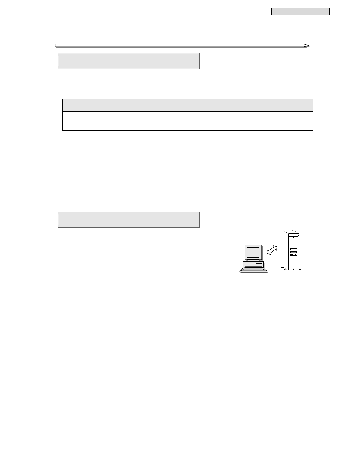
1. Interface setting: WS (work station) (default setting)
Use software such as the power management software on the supplied CD-ROM to
manage the power and shut down the computer by performing communication
between the UPS and computer (personal computer, work station, etc.).
For details on the power management software, see §12 “Using Power Management
Software” or the User’s Guide on the supplied CD-ROM.
2. Interface setting: Standalone (standalone)
Use the standard UPS service function* of the operating system (NetWare, Windows
NT, etc.) to shut down the UPS automatically.
Signal Names External Appearance
②
CARD I/F
Card interface
connector
Connect the connection cable of an optional Sanyo LAN interface card.
When connecting a LAN interface card, set the interface to WS (work station). For the
interface setting procedure, see §3.5 “Setting PC Interface” in the
LCD Panel Operatin
g
Manual
.
For the LAN interface card installation, see the manual attached in the LAN interface card.
①
②
D-sub 9-pin Male
⑨
⑧
⑦
⑥
⑤
④
③
②
①
Fixing Screw
(inch)
⑤
③
For details on the setting procedure, see §13 “Using Standard OS UPS Service.”
When using an operating system (Windows 95 and 98, etc.) that does not have a UPS service
function, do not connect the supplied communication cable. The backup operation may not be
possible in the event of a power outage.
When using a combination of the UPS service function and the power management software
(option) with a serial connection, set the interface to WS (work station). If the UPS is used
when the setting is set to standalone, the UPS may shut down suddenly when there is a power
* Notes on using the UPS service function
⑥
④
The PC interface connector and
card interface connector cannot be
used at the same time.
Note
2 RXD
3 TXD
4 DTR
5 GND
6 DSR
7 RTS
8 CTS
1 DCD
9 RI
Part Names
13
No. Name Function
③
SIGNAL I/F
Contact signal
interface connector
Outputs status information of the UPS such as a power outage or voltage drop.
External Transmission Signals and Shutdown Input Signals
Signal Name
Explanation
Pin No. and
Status when
Operating
AC input error
This signal is output when there is a power outage or
voltage error of the utility power supply.
1-8: ON
2-8: OFF
Battery voltage drop
This signal is output when the battery voltage drops
to or below the specified value (approx. 178 V).
3-11: ON
AC output
This signal is output when AC output is being
supplied to a load device.
4-7: ON
15-7: OFF
Inverter output
This signal is output when inverter output is being
supplied to a load device.
14-8: ON
Bypass output
This signal is output when the utility power supply is
being supplied from the bypass circuit.
5-12: ON
Output signal
Device error
This signal is output when a device error occurs.
6-13: ON
Input signal
UPS shutdown
The UPS is shut down as a result of receiving 5 V DC
(pulse signal of at least 4 sec.) during battery
operation when there is a power outage. Current
flows at approximately 5 mA when the power is on.
This is enabled when the interface is set to
Standalone. For the setting procedure, see §3.5
“Setting PC Interface” in the
LCD Panel Operating
Manual.
9-10
External Transmission Signals and Electrical Characteristics
Interface: Relay non-voltage contact signal
Contact rating: 100 V AC / 50 V DC, 0.1 A
Terminal Names External Appearance
④
Switches for
independent contact
signals
Setting these switches to “OFF” makes each contact of the external transmission signals
independent.
Refer to contact interface connector
③
, and set “ON” or “OFF” according to how the UPS will
be used by the customer. The switches are all set to “ON” at the time of shipment from the
factory.
External Appearance
When all of
1 to 4 are in
the “ON” state
Set them to “OFF” when using each contact signal as an
independent circuit.
Set them to “ON” when using each contact signal as a common
COM circuit.
When connecting an inductive/capacitive load, make sure the contact rating is not exceeded.
Note
D-sub 15-pin Female
①
②
③
④
⑤
⑥
⑦
⑧
Fixing screw M3
⑨
⑩
⑪
⑫
⑬
⑭
⑮
A
C input error
2
S1 to S4 :
Switches for independent contact signals (see ④)
3
12
4
7
14
5
COM
Battery voltage drop
AC output
COM
Inverter output
Bypass output
Device error
UPS shutdown
15
1
8
11
6
13
9
10
S1
S2
S3
S4
1
COM
COM
COM
 Loading...