

Page 1
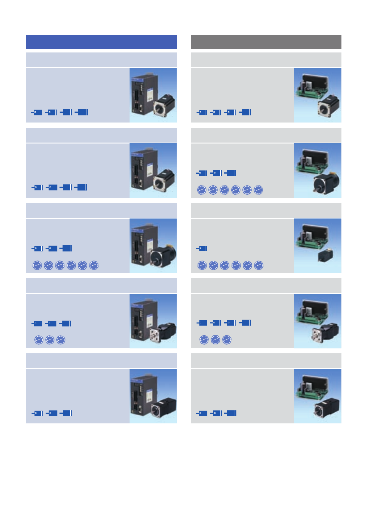
5-PHASE STEPPING SYSTEMS
Ver.3
Page 2
)
5-phase STEPPING SYSTEMS
)
)
)
)
Extensive lineup
F series driver features
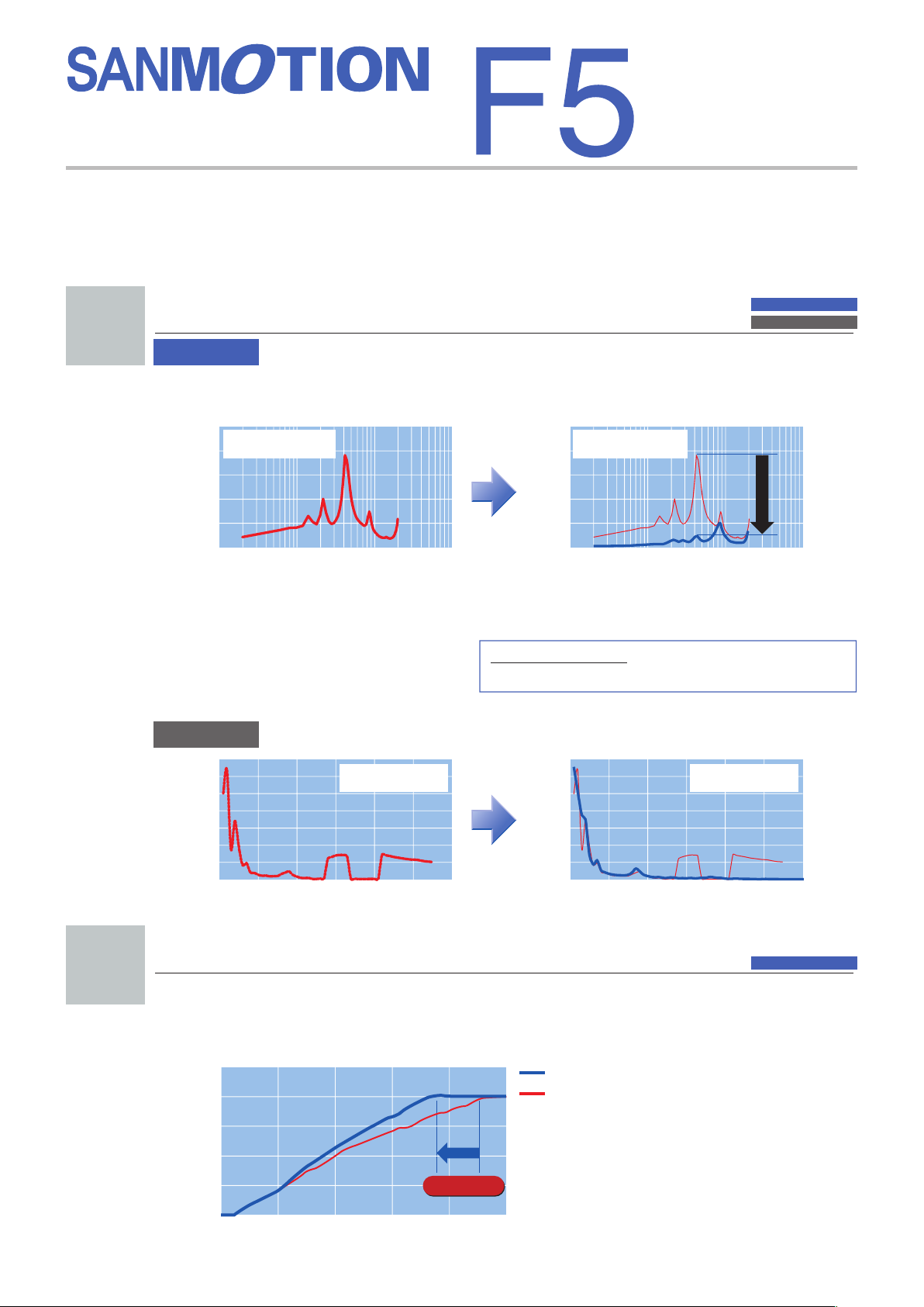
Lower vibration
1
AC input
■
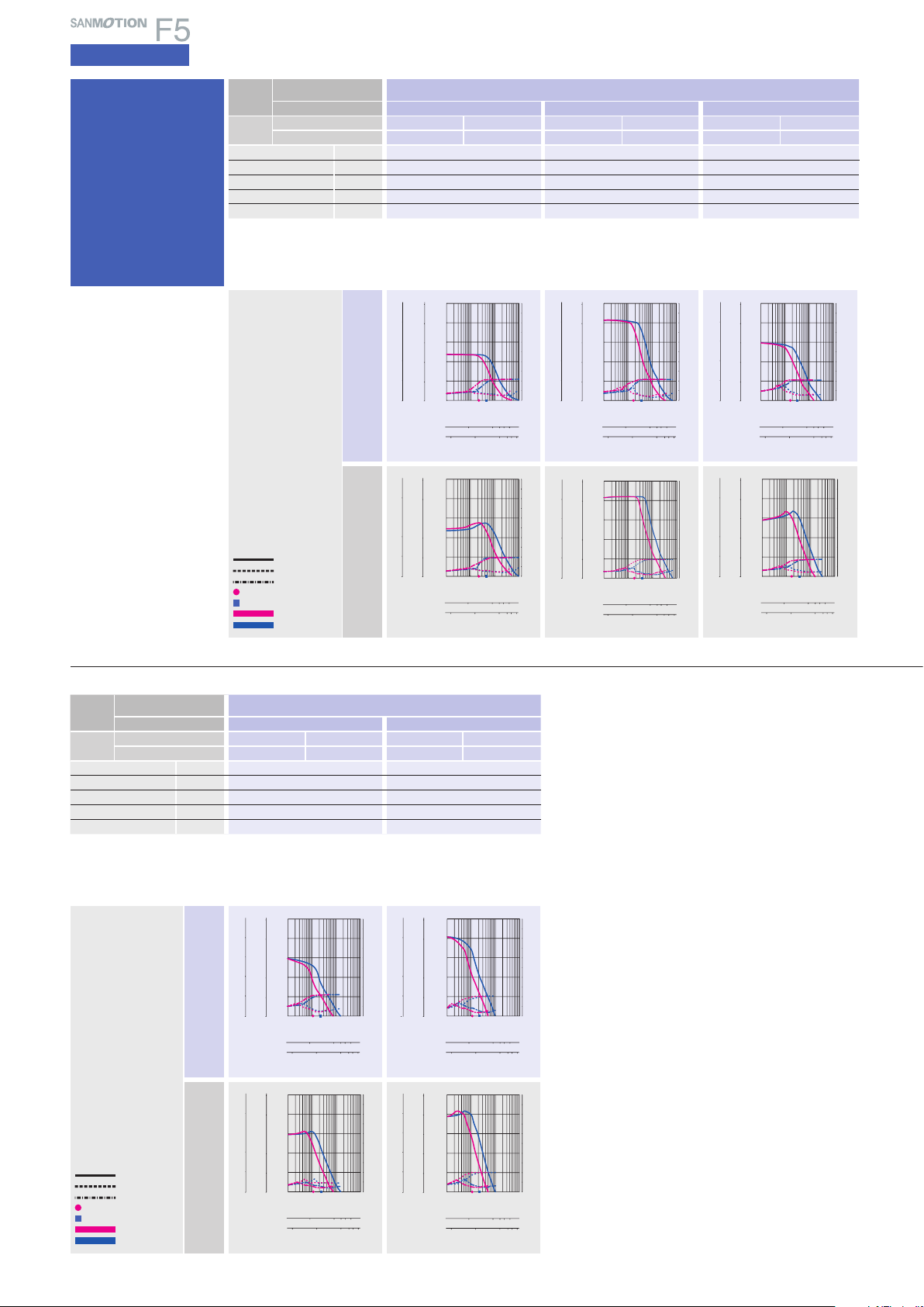
Automicro function and microstepping system enables further reduction of vibration
compared to current models.
Rotation-vibration characteristics(Full-step
1
Motor : 103F7851-7041
Power source voltage
0.8
Winding current : 0.75A/phase
0.6
0.4
0.2
TG ripple voltage
(Vrms) (Vrms)
0
0.01
■
Automicro function
Vibration suppression is executed internally and independently from the controller.
: 100V AC
0.1
Number of rotations(S1)
1 10
F series DRIVER
F series MOTOR
M series MOTOR
Rotation-vibration characteristicsx(1 / 250
1
Motor : 103F7851-7041
Power source voltage
0.8
Winding current : 0.75A/phase
0.6
0.4
0.2
TG ripple voltage
0
0.01 0.1 1 10
: 100V AC
Number of rotations(S1)
AC input
DC input
2
■
Microstepping system
The basic step angle is divided by a maximum of
1 / 250 using 16 selectable resolution levels to enable
smooth and vibration-free operation.
0.72
1 to 250 divisions
=
0.72 to 0.00288degrees/pulse
DC input
350
300
250
200
150
100
50
Speed variation(%)
0
0123 45 6
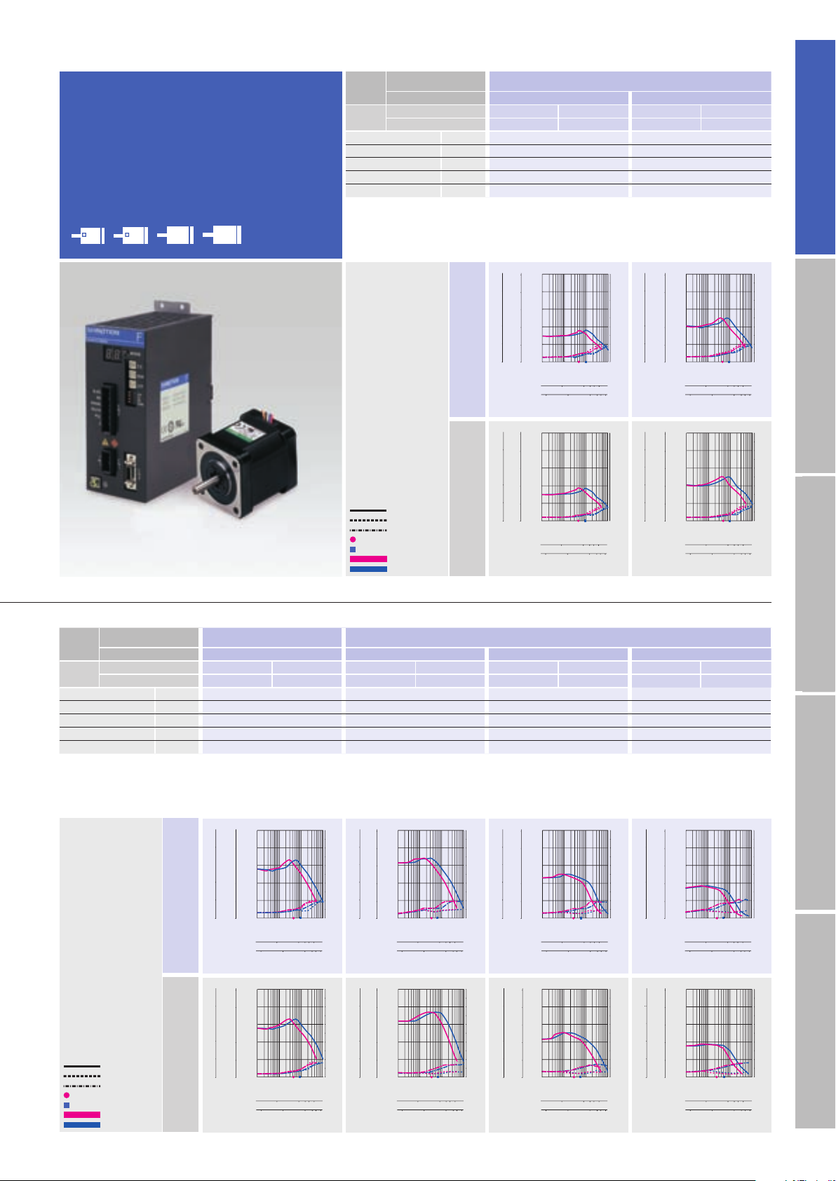
Current model
Motor : 103F7852-8241
Power source voltage:DC24V
Excitation method:Half-step
Number of rotations(S
350
300
250
200
150
100
50
Speed variation(%)
0
1
0123 45 6
Shoter cycle time
■
Improved response(up to 10% compared to current models)shortens the machine cycle
New model
Motor : 103F7852-8241
Power source voltage:DC24V
Excitation method:Half-step
Number of rotations(S
1
AC input
time for repetitive operations.
Load:JL:0.6×10⁻⁴kg・m2(2050.3×10-4lb・in2)
)
-1
1000
800
F series driver
Current model
600
400
Number of rotations(min
200
0
2 4 6 8 10
Rise time(ms
Reduced 10%
1
Page 3
3
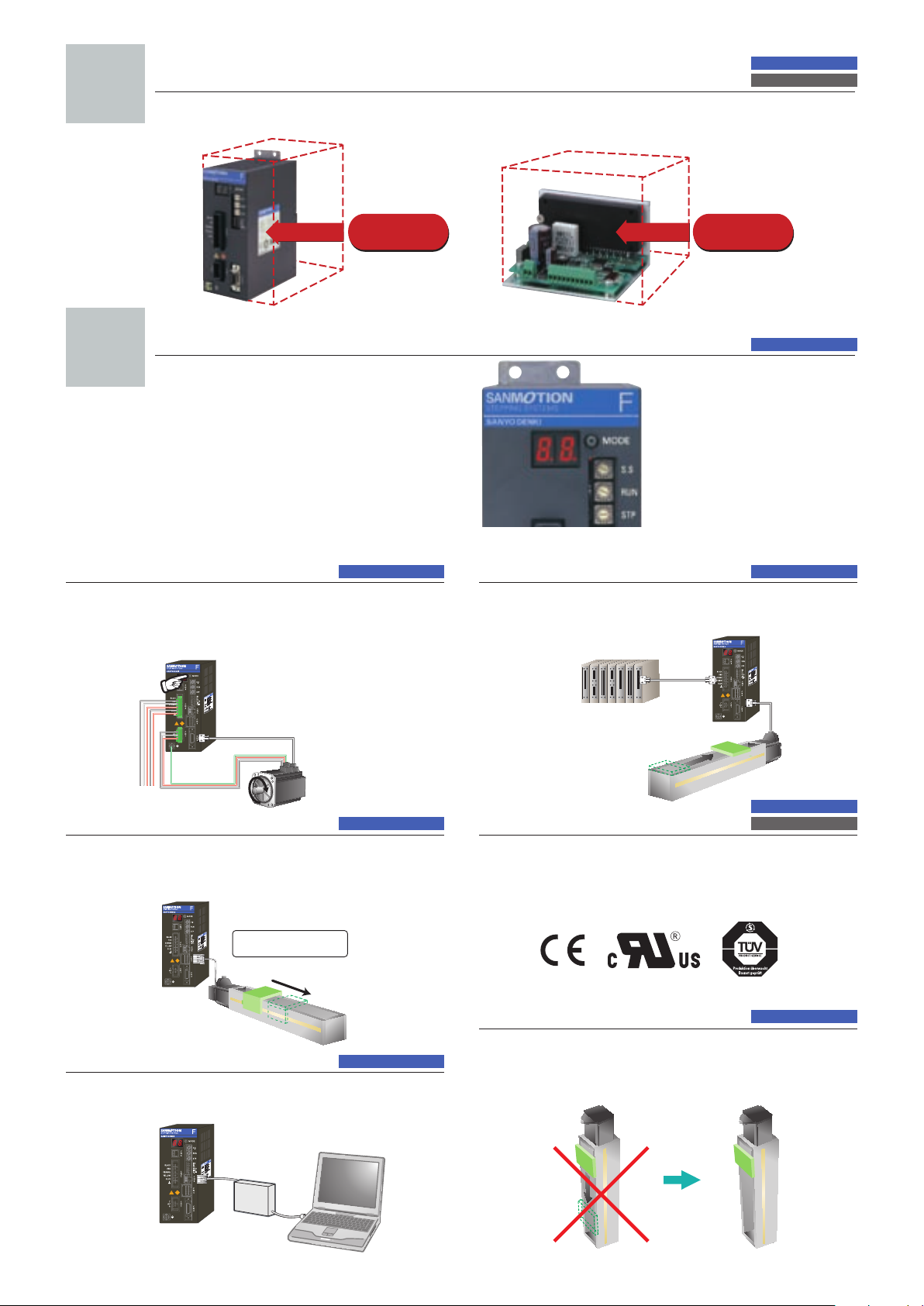
Capable of JOG operation
)
AC input
Control panel space is reduced
■
Volume is reduced by up to 50% for AC input types and 45% for DC input types compared
DC input
to current models.
50% reduction
for 200V types
Easy maintenance
4
Test run function(JOG
On-board JOG operation function is available for testing motor
and amplifier connection without the need to connect to host
device.
■
2-digit 7-segment LED displays
operating status and alarm for
easy troubleshooting and
faster system recovery.
)
With built-in positioning func tion
without connecting to host
device
45% reduction
for 24V types
AC input
General-purpose I/O input
for positioning
System positioning is easily executed by using general-purpose
I/O from an upper-level controller
program numbers.
PLC
(
Designate
program
number”1”
AC inputAC input
With built-in positioning func tion
PLC)to designate preset
Encoder I/F Control
With built-in positioning func tion
Motor stall detection is possible by connecting a motor encoder. 500P/
(
1000/2000 multiplier function)line driver method.
R
Highly precise positioning
is possible
Load
PC-based setup monitor
With built-in positioning func tion
Parameter and program settings can be made from the bundled
setup software.
Parameter(position, speed
Program settings
AC input
AC input
F motor
Compliance with
international standards
Th e standard spe cifi cation S ANMOTION F series s tep ping
driver complies with UL and EN safety standards . Step ping
motors complying with UL an
r
equest. EMC filters are also available to comply with the EMC
directive.
d EN standards are available upon
Brake control
Automatic brake activation timing control is available when
using electromagnetic brake motors.
• Internal power source for brake
F motor
Tare weight
(
FP type
)
AC input
DC input
AC input
2
Page 4
F series DRIVER
F series MOTOR
M series MOTOR
5-phase STEPPING SYSTEMS
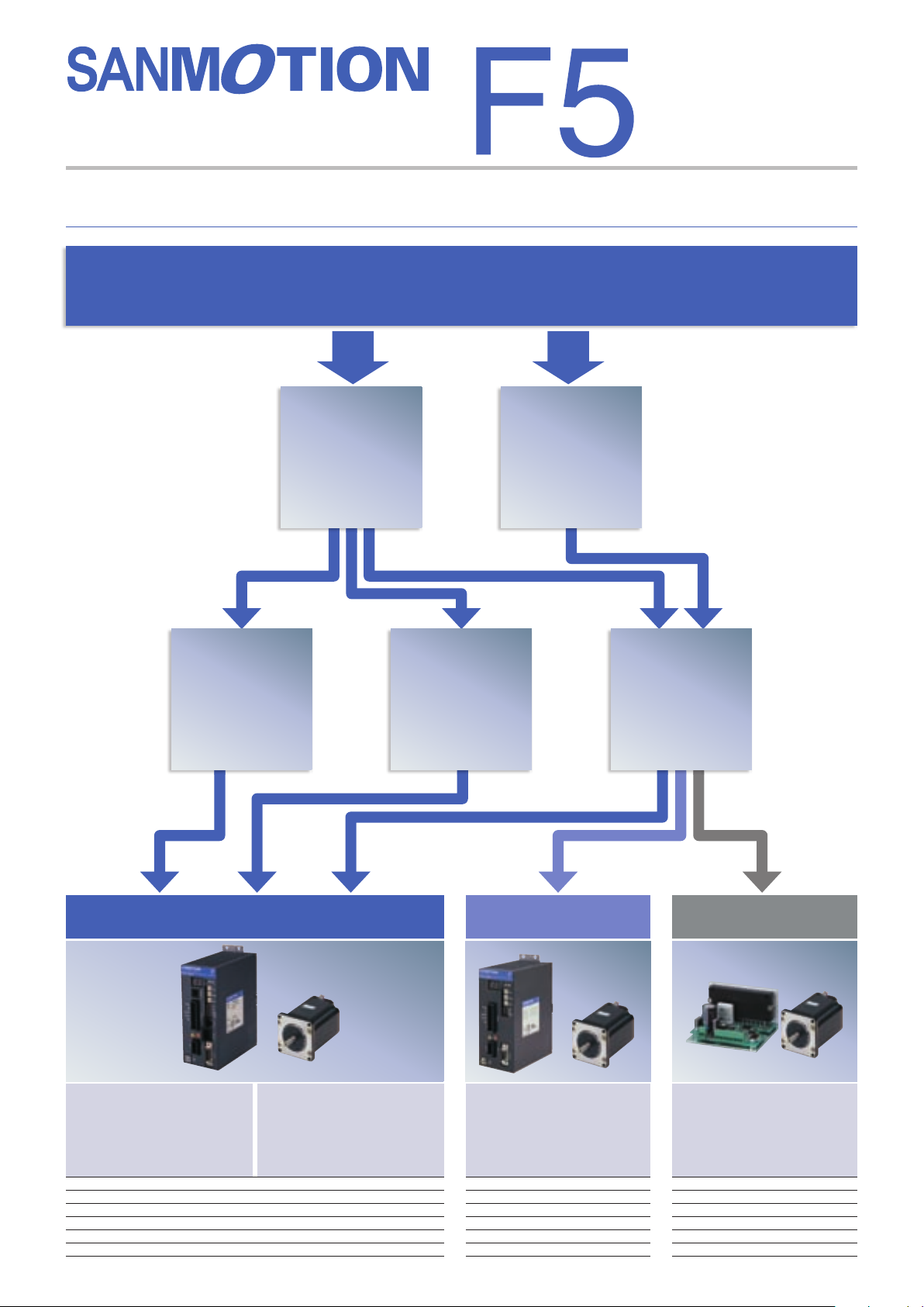
Control method
How do you want to control the equipment ?
The F series offers the choice of 3 different control methods
Point command
control using
PLC I/O
AC power
source
Network control
using serial
communication
(
RS-485
)
DC power
source
Control using a
pulse generator
AC input
with built-in positioning function
Startup via I/O :
Initiate program c ont aining
speed, acceleration/deceleration,
and travel distance commands
stored in the driver via the I/O.
System confi guration diagram P7
Set part number nomenclature P9
Motor specifi cations P47 to 58
General specifi cations P 25
Motor dimension drawing P61 to 67
Driver dimension drawing P68
3
Startup via serial
communication:
Control by sending data for
speed, acceleration/deceleration,
and travel distance commands
via serial communication.
・
26, 60
AC input
standard type
Motion is generated by pulse
input commands from an
upper-level controller.
System confi guration diagram P5
Set part number nomenclature P9
Motor specifi cations P47 to 58
General specifi cations P23
Motor dimension drawing
Driver dimension drawing P68
・
24, 60
P61 to 67
DC input
Motion is generated by pulse
input commands from an
upper-level controller.
System confi guration diagram P29
Set part number nomenclature P31
Motor specifi cations P47 to 58
General specifi cations P43
Motor dimension drawing
Driver dimension drawing P68
・
44, 60
P61 to 67
Page 5
Motor flange size
Motor flange size
Motor flange size
Set model
Motor flange size
Motor flange size
Motor flange size
ø
106
Motor flange size
)(ø4.17inch)
DC inputAC input
Standard model
The standard set includes a F series
driver and a F series motor.
ø
86ø106
60
42
(□1.65inch)(□2.35inch)(ø3.39inch)(ø4.17inch)
CE / UL model
The UL/CE set includes a F Series
driver and a M Series motor.
ø
ø
106
86
60
42
(□1.65inch)(□2.35inch)(ø3.36inch)(ø4.17inch)
Low-backlash gear model
This set includes a low backlash gear that
uses tapered hobbed gears to engage the
final stage of the speed reduction mechanism.
Motor flange size
42
(□1.65inch)(□2.35inch)(ø3.39inch)
Reduction gear ratios
3.617.2110120130136
ø
86
60
1
P.12
P.14
P.16
Standard model
The standard set includes a F series
driver and a F series motor.
ø
86
28 42
(□1.65inch)(□1.10inch) (□2.35inch)(ø3.39inch
60
Low-backlash gear model
This set includes a low backlash gear that
uses tapered hobbed gears to engage the
final stage of the speed reduction mechanism.
Motor flange size
42
(□1.65inch)(□2.35inch)(ø3.39inch)
Reduction gear ratios
3.617.2110120130136
ø
86
60
1
Spur gear model
This set utilizes a spur gear in the
speed reduction mechanism.
Motor flange size
28
(□1.10inch)
Reduction gear ratios
3.617.2110120130150
1
P.33
P.35
P.38
Harmonic gear model
This set utilizes a harmonic gear.
ø
86
60
42
(□1.65inch)(□2.35inch)(ø3.39inch)
Reduction gear ratios
301501100
1
Electromagnetic brake model
This set utilizes a non-excitation
electromagnetic brake to maintain
position in vertical load applications
and hold load even during power off.
ø
86
60
42
(□2.35inch)(□1.65inch) (ø3.39inch)
P.19
P.21
Harmonic gear model
This set utilizes a harmonic gear.
ø
86
28 42
(□1.65inch)(□1.10inch) (□2.35inch)(ø3.39inch)
Reduction gear ratios
301501100
60
1
Electromagnetic brake model
This set utilizes a non-excitation
electromagnetic brake to maintain
position in vertical load applications
and hold load even during power off.
ø
86
60
42
(□2.35inch)(□1.65inch) (ø3.39inch)
P.39
P.41
4
Page 6
5-phase STEPPING SYSTEMS
+50 mm
+.16
(
)
+50 mm
+.16
AC input
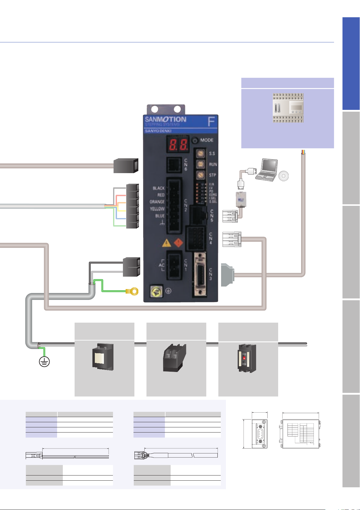
System configuration
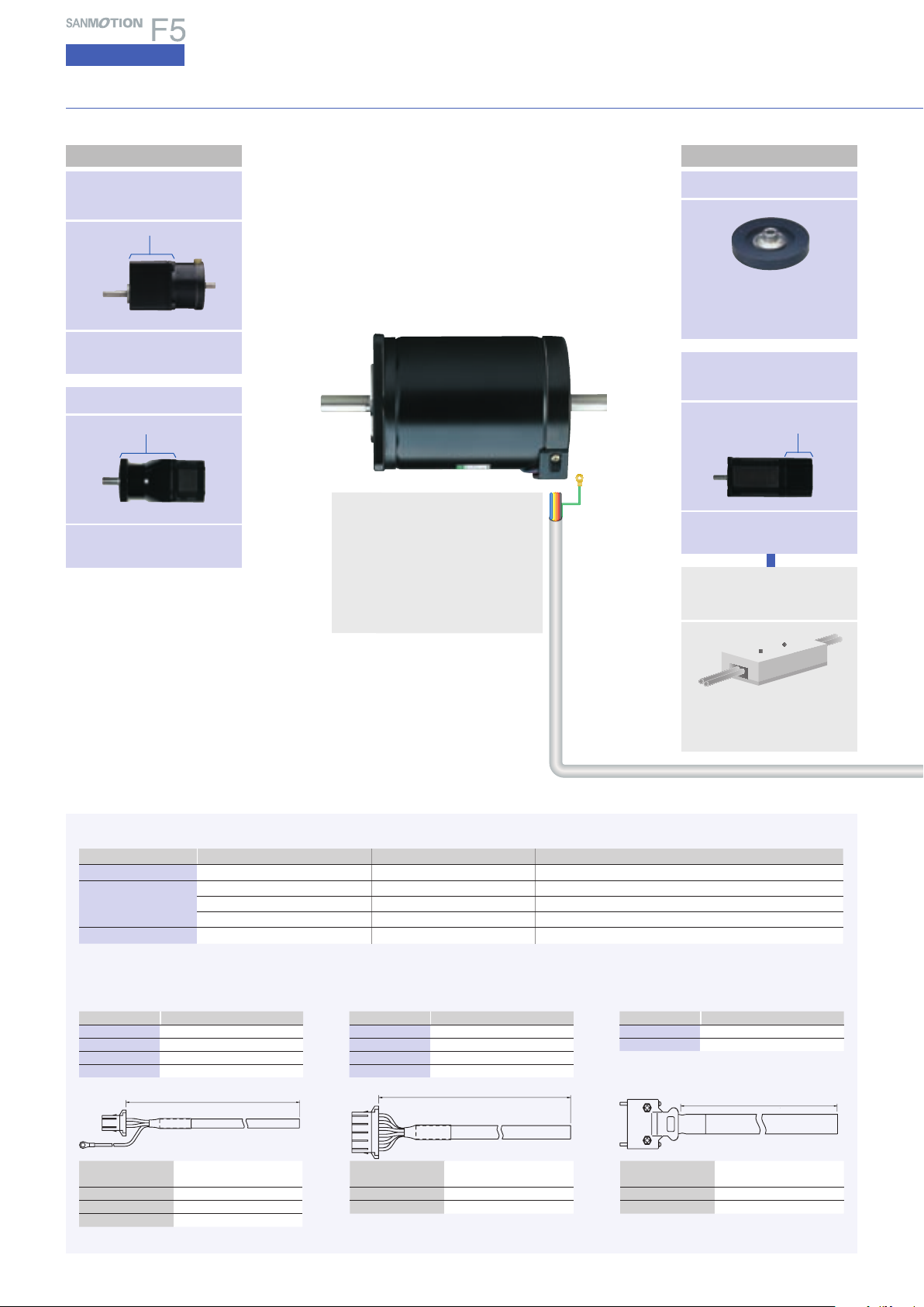
Standard type
Flange side
Low-backlash gear
model
Low backlash gear
Motor flange size
□
□
(
42mm
(
1.65inch)/□60mm
□2.35inch)/φ86mm
φ
(
3.39inch
Harmonic gear model
Harmonic gear
Motor flange size
□
□
(
42mm
1.65inch)/□60mm
□
(
2.35inch)/φ86mm
φ
(
3.39inch
End-cap side
Damper
Magnetic dampers can be
selected according to the
required inertia.
)
Electromagnetic
brake model
Electromagnetic brake
Standard model : F series motor
□
42mm( □1.65inch)/□60mm
φ
(
/φ86mm
)
CE / UL model : M series motor
□
3.39inch)/φ106mm
42mm( □1.65inch)/□60mm
/φ86mmφ3.39inch)/φ106mm
●
Motors are available in standard or vacuum
types.
□
(
(
□
(
φ
(
2.35inch
φ
4.17inch
2.35inch
4.17inch
)
)
)
)
Motor flange size
□
42mm( □1.65inch)/□60mm
□
(
2.35inch)/φ86mm
φ
(
3.39inch
Brake power source
(
DC24V
)
)
B
●
Motor cable(optional
■
Bundled connectors(set models only
Connec tor typ e Housing Contac t Applicable moto r flange size
1
●
AC power connector
2
●
Motor connec tor
3
●
I/O signal connector
■
Optional cables
A
●
AC power cable
L : m(feet)Part number
(
)
10
5
3
1
(
(
(
32.81
16.40
9.84
3.28
)
)
)
PM-C03P1000-05
PM-C03P0 500-05
PM-C03P0300-05
PM-C03P0100-0 5
− 0 mm
L
1-178128-2(AMP
1-178128-6(AMP
1-178128-6(AMP
1-178128-6(AMP
10314-52A0-008(3M
( feet)
− 0
)
)
)
)
)
B
●
10
(
5
(
3
(
1
)
1-175218-5(AMP
1-175216-5(AMP
1-175217-5(AMP
1-175218-5(AMP
10114-3000PE(3M
Motor cable
L : m(feet)Part number
(
)
32.81
)
16.40
)
9.84
)
3.28
)
)
)
)
PM-C06M1000-11
PM-C06M0500 -11
PM-C06M0300 -11
PM-C06M0100-11
+50 mm
( feet)
− 0 mm
L
)
+.16
− 0
─
□
42mm
□
60mm
φ
106mm
─
□
(
1.65inch
□
(
2.35inch), φ86mm
φ
(
4.17inch
C
●
I/O signal cable
L : m(feet)Part number
(
6.56
2
(
3.28
1
Required for brake-equipped
stepping motor models.
)
)
)
)
)
φ
(
3.39inch
PM-C14S0200-03
PM-C14S0100-03
feet
− 0
− 0 mm
L
)
Leadwire
Housing 1-178128-2(AMP
Contact 1-175218-5(AMP
Round-type crimp contact
●
Cables 10m(32.81 feet) or longer are available
upon request.
600V vinyl cab tire cable
3-c ore AWG16
1.25M4(J.S.T. Mfg Co.
5
(
1.25mm
)
)
2
)
)
Leadwire
Housing 1-178128-6(AMP
Contact 1-175218-5(AMP
●
Cables 10m(32.81 feet) or longer are available
upon request.
600V vinyl cab tire cable
6-core AWG16
(
0.75mm
)
)
2
)
Leadwire
Shell 10314 -52 A0- 008(3M
Plug 10114-3000PE(3M
7-pair PVC shielded cable
(
AWG28
0.08mm
2
)
)
)
Page 7
2
●
Motor connector
(
bundled
)
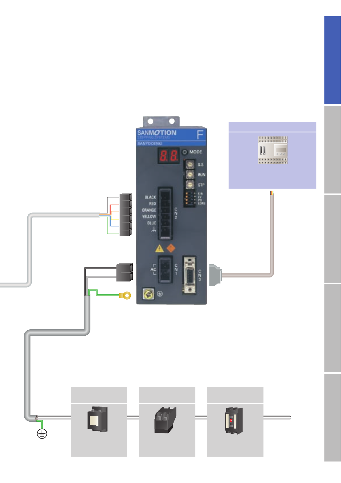
Host Devices
PLC
PLC and controllers are available as
the host device.
C
●
I/O signal cable
(
optional
)
AC inputInput / Output signal standardDC inputStepping motorDimensions
1
●
AC power connector
(
A
●
AC power cable(optional
Noise filter
bundled
)
)
3
Electromagnetic
contactor
●
I/O signal connector(bundled
Molded case
circuit breaker
)
Single
phase
(t)
AC100V
to
AC230V
)
(
r
Filters out incoming
noise from power line
Switches driver power
on/off. Use together
with a surge protector.
Protects the power line.
Cuts off circuit in the
event of overcurrent.
6
Page 8
5-phase STEPPING SYSTEMS
(
)
+50 mm
+.16
AC input
System configuration
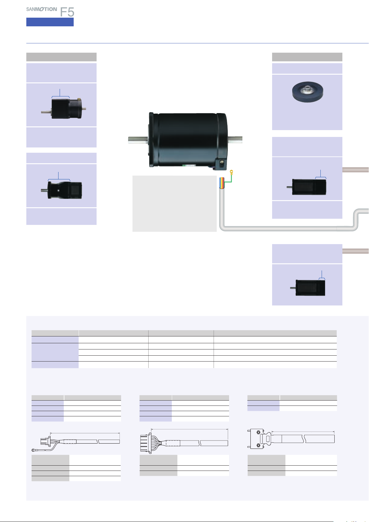
With built-in positioning function
Flange side
Low-backlash gear
model
Low backlash gear
Motor flange size
□
□
(
42mm
(
1.65inch)/□60mm
□2.35inch)/φ86mm
φ
(
3.39inch
Harmonic gear model
Harmonic gear
Motor flange size
□
□
(
42mm
1.65inch)/□60mm
□
(
2.35inch)/φ86mm
φ
(
3.39inch
End - cap side
Damper
Magnetic dampers can be
selected according to the
required inertia.
)
Electromagnetic
brake model
Electromagnetic brake
Standard model : F series motor
□
42mm( □1.65inch)/□60mm
φ
(
/φ86mm
CE / UL model : M series motor
□
/φ86mm
)
●
types.
3.39inch)/φ106mm
42mm( □1.65inch)/□60mm
φ
(
3.39inch)/φ106mm
Motors are available in standard or vacuum
□
(
(
□
(
(
2.35inch
φ
4.17inch
2.35inch
φ
4.17inch
)
)
)
)
B
●
Option cable for motor
Motor flange size
□
42mm( □1.65inch)/□60mm
□
(
2.35inch)/φ86mm
(
φ
3.39inch
)
■
Bundled connectors(set models only
Connec tor typ e Housing Contac t Applicable moto r flange size
1
●
AC power connector
2
●
Motor connec tor
3
●
I/O signal connector
■
Optional cables
A
●
AC power cable
L : m(feet)Part number
(
)
10
5
3
1
(
(
(
32.81
16.40
9.84
3.28
)
)
)
PM-C03P1000-05
PM-C03P0 500-05
PM-C03P0300-05
PM-C03P0100-0 5
L
1-178128-2(AMP
1-178128-6(AMP
1-178128-6(AMP
1-178128-6(AMP
10314-52A0-008(3M
+.16
+50 mm
( feet)
− 0
− 0 mm
)
)
)
)
)
B
●
10
(
5
(
3
(
1
)
1-175218-5(AMP
1-175216-5(AMP
1-175217-5(AMP
1-175218-5(AMP
10114-3000PE(3M
Motor cable
L : m(feet)Part number
(
)
32.81
)
16.40
)
9.84
)
3.28
)
)
)
)
PM-C06M1000-11
PM-C06M0500 -11
PM-C06M0300 -11
PM-C06M0100-11
+50 mm
( feet)
− 0 mm
L
─
□
□
φ
)
+.16
− 0
─
42mm
60mm
106mm
□
(
1.65inch
□
(
2.35inch), φ86mm
φ
(
4.17inch
C
●
I/O signal cable
L : m(feet)Part number
(
6.56
2
(
3.28
1
Encoder equipped
model
Optional
)
)
)
)
φ
(
3.39inch
PM-C 20S0200- 01
PM-C 20S0100-01
− 0 mm
L
Encoder
)
feet
− 0
Leadwire
Housing 1-178128-2(AMP
Contact 1-175218-5(AMP
Round-type crimp tool
●
Cables 10 m(32.81 feet) or longer are available
upon request.
600V vinyl cab tire cable
3-c ore AWG16
1.25M4(J.S.T.
7
(
1.25mm
)
)
)
2
)
Leadwire
Housing 1-178128-6(AMP
Contact 1-175218-5(AMP
●
Cables 10 m(32.81 feet) or longer are available
upon request.
600V vinyl cab tire cable
6-core AWG16
(
0.75mm
)
)
2
)
Leadwire
Shell 10320-52A0-0 08(3M
Plug 10120-3000PE(3M
10-pair PVC shielded cable
(
AWG28
0.08mm
2
)
)
)
Page 9
(
)
+50 mm
+.16
D
63.5(2.52)
27(1.06)
50(1.77)
●
Brake cable
2
●
Brake connector
2
●
Motor connector
(
bundled
)
1
●
AC power
connector
(
bundled
AC inputInput / Output signal standardDC inputStepping motorDimensions
Host Devices
PLC
PLC and controllers are available as
the host device.
G
●
RS232C
J
●
Software
F
●
Converter
H
●
Cable
RS485
E
●
Encoder cable
)
A
●
AC power cable
(
optional
D
●
Brake cable
L : m(feet)Part number
(
)
32.81
10
(
16.40
5
(
)
9.84
3
(
)
3.28
1
Leadwire
Housing 1-1318120-3(AMP
Contact 1318107-1(AMP
)
PM-C03B1000-01
PM-C03B0500-01
PM-C03B0300-01
PM-C03B0100-01
+50 mm
− 0 mm
L
PVC cable
AWG22(0.3mm
)
Noise filter
Filters out incoming
noise from power line.
+.16
( feet)
− 0
2
)
)
)
Electromagnetic
contactor
Switches driver power
on/off. Use together
with a surge protector.
E
●
Cable for encoder use
L : m(feet)Part number
(
)
32.81
10
(
16.40
5
(
)
9.84
3
(
)
3.28
1
Leadwire
Housing 1-1318118-6(AMP
Plug 1318107-1(AMP
)
PM-C12S1000-01
PM-C12S0500-01
PM-C12S0300-01
PM-C12S0100-01
feet
− 0
− 0 mm
L
4-pair PVC shielded cable
AWG22(0.3mm
2
)
)
)
3
●
I/O Signal
Connector
(
bundled
)
Molded case
circuit breaker
Protects the power line.
Cuts off circuit in the
event of overcurrent.
F
●
Converter [unit : mm(inch)]
F
●
Part number for RS232C-RS485 converter :
232485CFP01-01
G
●
RS232 cable is supplied by user.
H
●
Part number for FP communications cable :
PM-C08S0100-05
J
●
Part number for bundled software :
SFPA1W-01
(
please download from website
C
●
I/O signal cable
(
optional
(t)
)
(
r
Func Parity
No.
F.Dup
1
2
Term
Echo
3
C N 2
to+5V
4,5
toGND
6,7
None
8
Single
phase
AC100V
to
AC230V
C N 3
bps
UseNone
80
9600
91
19200
C N 1
38400
A2
B3
57600
115200
C4
D5
128000
153600
E6
307200
F7
DSWRSWRX TX
)
)
8
Page 10
5-phase STEPPING SYSTEMS
AC input
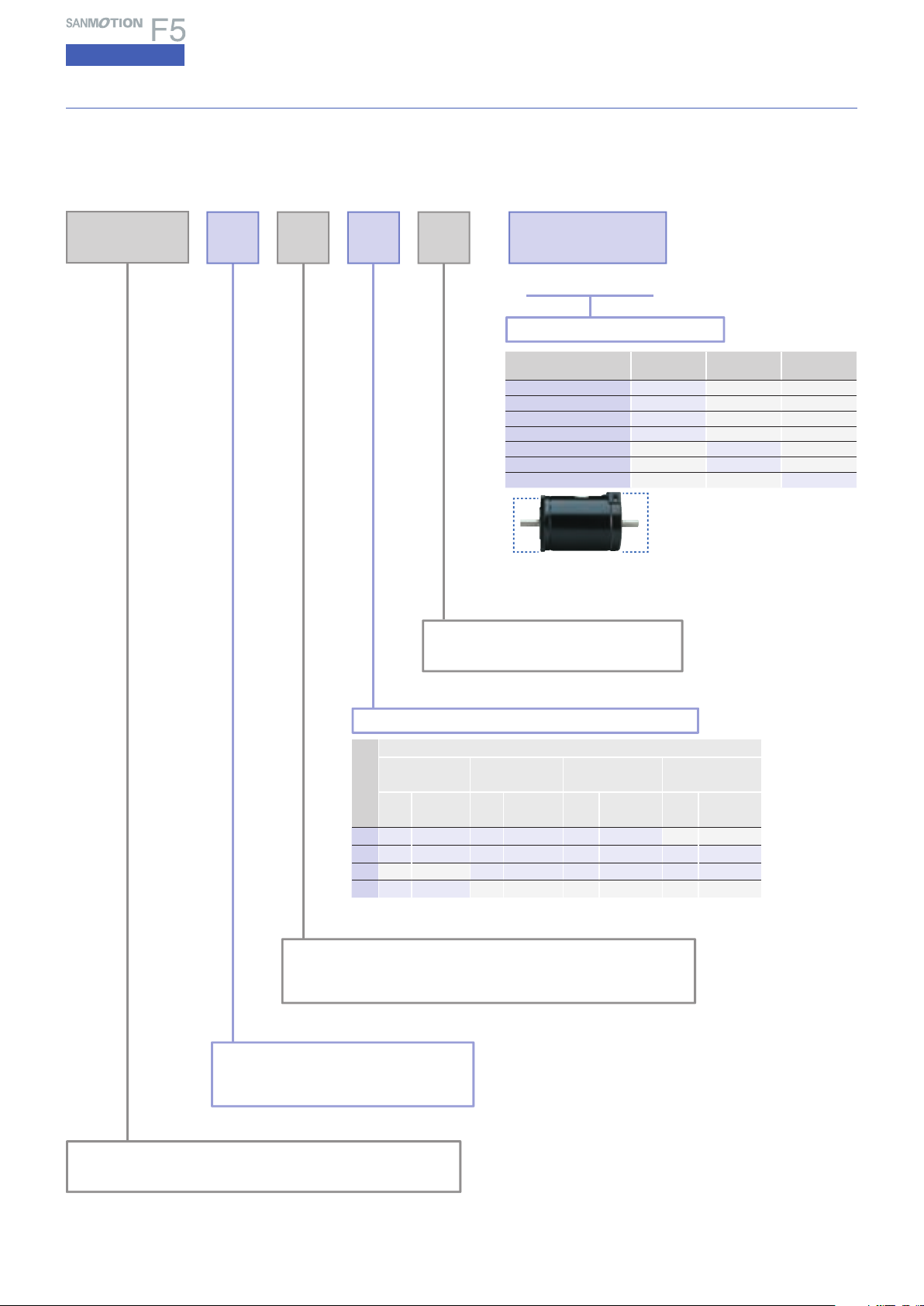
Part number convention
The following part number specifies a system with an F series driver (type code : FS1W075P) and a single
(
shaft F series motor
type code : 103F7851-7041),□60mm
motor length, equipped with low-backlash gear
F S
F 78 1 S - C X 3.6
(
reduction ratio of 1/3.6).
□
(
2.36inch) square flange, and 46.5mm(1.83inch)
▲
Ⅰ▲Ⅱ
▲
Ⅲ
System spec
System type
Spur gear
Low-backlash gear
Harmonic gear
No system at Flange side
Electromagnetic brake
No system at End cap side
Gear ratio
(
Flange side
●
●
●
) (
Spur gear
Low-backlash gear
Harmonic gear
End cap side
●
Ⅰ Ⅱ Ⅲ
(
Flange side
)
(
End cap side
G
C
H
X
─
─
─ ─
Electromagnetic
)
)
(
─ ─
─ ─
─ ─
─ ─
B
X
Reduction ratio
─
─
3.6 to 100
)
Stepping motor total length(Standard model )
Motor flange size
□
42mm
□
(
1.65inch
Code
Type
code
1 5505 34(1.34)7851 46.5(1.83)8581 62.2(2.45
2 5508 40(1.57)7852 55(2.17)8582 92.2(3.63)89582
3 7853 87.5(3.44)8583 125.9(4.96)89583 221.3(8.71
4 5510 49(1.93
Stepping motor flange size
□
:
55
42mm( □1.65inch
□
:
78
60mm( □2.36inch
Stepping motor series name
:
F
F series motor
:
M
M series motor(CE/UL
Stepping motor shaft spec
2.36inch
Motor leng th :
(
mm
inch
φ
86mm
φ
106mm
D : Double shaft
)
)
S : Single shaft
□
)
(
Motor length :
mm
)
(
)
inch
)
Type
code
) 85:
) 89:
60mm
□
φ86mm
φ
(
3.39inch
Type
code
φ
(
3.39inch
φ
(
4.17inch
)
Motor leng th :
(
)
mm
inch
)
)
)
φ
(
Type
code
106mm
φ
4.17inch
Motor leng th :
mm
163.3(6.43
)
(
)
inch
)
)
FS : AC Power source Standard type
FP : AC Power positioning-function-included type
9
Page 11
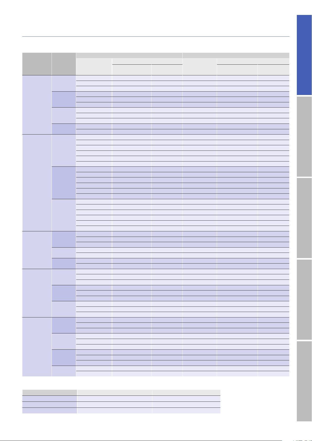
Packaged Sale Model Configuration
This is a set comprising a driver,
motor and connectors.
AC pulse input type
Single shaft Double shafts
Model
Standard
model
Low-backlash
gear model
Harmonic
gear model
Electromagnetic brake
model
CE / UL
model
Motor
flange size
□
42mm
□
60mm
φ
86mm
φ
106mm
□
42mm
□
60mm
φ
86mm
□
42mm
□
60mm
φ
86mm
□
42mm
□
60mm
φ
86mm
□
42mm
□
60mm
φ
86mm
φ
106mm
Set part
number
FSF551S 103F5505-7041 PM-AP-065 FSF551D 103F5505-7011 PM-AP-065
FSF552S 103F5508-7041 PM-AP-065 FSF552D 103F5508-7011 PM-AP-065
FSF554S 103F5510-7041 PM-AP-065 FSF554D 103F5510-7011 PM-AP-065
FSF781S 103F7851-7041 PM-AP-064 FSF781D 103F7851-7011 PM-AP-064
FSF782S 103F7852-7041 PM-AP-064 FSF782D 103F7852-7011 PM-AP-064
FSF783S 103F7853-7041 PM-AP-064 FSF783D 103F7853-7011 PM-AP-064
FSF851S 103F8581-7041 PM-AP-064 FSF851D 103F8581-7011 PM-AP-064
FSF852S 103F8582-7041 PM-AP-064 FSF852D 103F8582-7011 PM-AP-064
FSF853S 103F8583-7041 PM-AP-064 FSF853D 103F8583-7011 PM-AP-064
FSF892S 103F89582-7041 PM-AP-063 FSF892D 103F89582-7011 PM-AP-063
FSF893S 103F89583-7041 PM-AP-063 FSF893D 103F89583-7011 PM-AP-063
FSF551S-CX3.6 103F5505-70CXA4 PM-AP-065 FSF551D-CX3.6 103F5505-70CXA1 PM-AP-065
FSF551S-CX7.2 103F5505-70CXB4 PM-AP-065 FSF551D-CX7.2 103F5505-70CXB1 PM-AP-065
FSF551S-CX10 103F5505-70CXE4 PM-AP-065 FSF551D-CX10 103F5505-70CXE1 PM-AP-065
FSF551S-CX20 103F5505-70CXG4 PM-AP-065 FSF551D-CX20 103F5505-70CXG1 PM-AP-065
FSF551S-CX30 10
FSF551S-CX36 103F5505-70CXK4 PM-AP-065 FSF551D-CX36 103F5505-70CXK1 PM-AP-065
FSF781S-CX3.6 103F7851-70CXA4 PM-AP-064 FSF781D-CX3.6 103F7851-70CXA1 PM-AP-064
FSF781S-CX7.2 103F7851-70CXB4 PM-AP-064 FSF781D-CX7.2 103F7851-70CXB1 PM-AP-064
FSF781S-CX10 103F7851-70CXE4 PM-AP-064 FSF781D-CX10 103F7851-70CXE1 PM-AP-064
FSF781S-CX20 103F7851-70CXG4 PM-AP-064 FSF781D-C
F
SF781S-CX30 103F7851-70CXJ4 PM-AP-064 FSF781D-CX30 103F7851-70CXJ1 PM-AP-064
FSF781S-CX36 103F7851-70CXK4 PM-AP-064 FSF781D-CX36 103F7851-70CXK1 PM-AP-064
FSF851S-CX3.6 103F8581-70CXA4 PM-AP-064 FSF851D-CX3.6 103F8581-70CXA1 PM-AP-064
FSF851S-CX7.2 103F8581-70CXB4 PM-AP-064 FSF851D-CX7.2 103F8581-70CXB1 PM-AP-064
FSF851S-CX10 103F8581-70CXE4 PM-AP-064 FSF851D-CX10 103F8581-70CXE1 PM-AP-064
FSF8
FSF851S-CX30 103F8581-70CXJ4 PM-AP-064 FSF851D-CX30 103F8581-70CXJ1 PM-AP-064
FSF851S-CX36 103F8581-70CXK4 PM-AP-064 FSF851D-CX36 103F8581-70CXK1 PM-AP-064
FSF551S-HX30 103F5505-70HXJ5 PM-AP-065 FSF551D-HX30 103F5505-70HXJ2 PM-AP-065
FSF551S-HX50 103F5505-70HXL5 PM-AP-065 FSF551D-HX50 103F5505-70HXL2 PM-AP-065
FSF551S-HX100 103F550
FSF781S-HX50 103F7851-70HXL4 PM-AP-064 FSF781D-HX50 103F7851-70HXL1 PM-AP-064
FSF781S-HX100 103F7851-70HXM4 PM-AP-064 FSF781D-HX100 103F7851-70HXM1 PM-AP-064
FSF851S-HX50 103F8581-70HXL4 PM-AP-064 FSF851D-HX50 103F8581-70HXL1 PM-AP-064
FSF851S-HX100 103F8581-70HXM4 PM-AP-064 FSF851D-HX100 103F8581-70HXM1 PM-AP-064
FSF551S-XB 103F5505-70XB41 PM-AP-065
FSF552S-XB 103F5508-70XB41 PM-AP-065
FSF554S-XB 103F5510-70XB41 PM-AP-065
FSF781S-XB 103F7851-70XB41 PM-AP-064
FSF782S-XB 103F7852-70XB41 PM-AP-064
FSF783S-XB 103F7853-70XB41 PM-AP-064
FSF851S-XB 103F8581-70XB41 PM-AP-064
FSF852S-XB 103F8582-70XB41 PM-AP-064
FSF853S-XB 103F8583-70XB41 PM-AP-064
FSM551S 103M5505-7041 PM-AP-065 FSM551D 103M5505-7011 PM-AP-065
FSM552S 103M5508-7041 PM-AP-065 FSM552D 103M5508-7011 PM-AP-065
FSM554S 103M5510-7041 PM-AP-065 FSM554D 103M5510-7011 PM-AP-065
FSM781S 103M7851-7041 PM-AP-064 FSM781D 103M7851-7011 PM-AP-064
FSM782S 103M7852-7041 PM-AP-064 FSM782D 103M7852-7011 PM-AP-064
FSM783S 103M7853-7041 PM-AP-064 FSM783D 103M7853-7011 PM-AP-064
FSM851S 103M8581-7041 PM-AP-064 FSM851D 103M8581-7011 PM-AP-064
FSM852S 103M8582-7041 PM-AP-064 FSM852D 103M8582-7011
FSM853S 103M8583-7041 PM-AP-064 FSM853D 103M8583-7011 PM-AP-064
FSM892S 103M89582-7041 PM-AP-063 FSM892D 103M89582-7011 PM-AP-063
FSM893S 103M89583-7041 PM-AP-063 FSM893D 103M89583-7011 PM-AP-063
Bundled driver model number : FS1W075P00
Set accessories
Motor model
number
3F5505-70CXJ4 PM-AP-065 FSF551D-CX30 103F5505-70CXJ1
51S-CX20 103F8581-70CXG4
5-70HXM5 PM-AP-065 F
Connector
Note)
number
PM-AP-064 FSF851D-CX20 103F8581-70CXG1 PM-AP-064
Set part
number
SF551D-HX100 103F5505-70HXM2 PM-AP-065
− − −
− − −
− − −
− − −
− − −
− − −
− − −
− − −
− − −
Step angle/0.72° Rated current 0.75A
Set accessories
Motor model
number
Connector
Note)
number
PM-AP-065
X20 103F7851-70CXG1 PM-AP-064
PM-AP-064
AC inputInput / Output signal standardDC inputStepping motorDimensions
Note) Includes a driver connector set (power supply connector, input/output signal connector) and a motor connector.
Connector model number Driver connector set model number Motor connector model number
PM-AP-063 PM-AP-078 4838971-1
PM-AP-064 PM-AP-078 4837994-1
PM-AP-065 PM-AP-078 4835758-1
10
Page 12
5-phase STEPPING SYSTEMS
AC input
Specifications
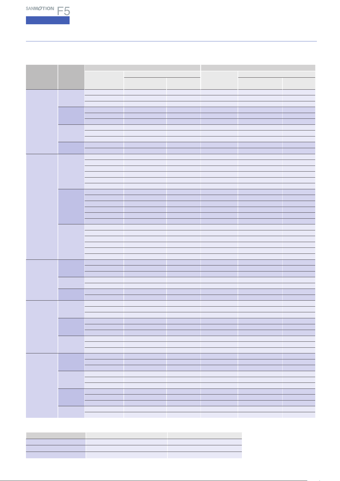
Packaged Sale Model Configuration
Type with built-in AC positioning function
Bundled driver model number : FP1W075P00
Single shaft Double shafts
Model
Standard
model
Low-backlash
gear model
Harmonic
gear model
Electromagnetic brake
model
CE / UL
model
Motor
flange size
□
42mm
□
60mm
φ
86mm
φ
106mm
□
42mm
□
60mm
φ
86mm
□
42mm
□
60mm
φ
86mm
□
42mm
□
60mm
φ
86mm
□
42mm
□
60mm
φ
86mm
φ
106mm
Set part
number
FPF551S 103F5505-7041 PM-AP-074 FPF551D 103F5505-7011 PM-AP-074
FPF552S 103F5508-7041 PM-AP-074 FPF552D 103F5508-7011 PM-AP-074
FPF554S 103F5510-7041 PM-AP-074 FPF554D 103F5510-7011 PM-AP-074
FPF781S 103F7851-7041 PM-AP-073 FPF781D 103F7851-7011 PM-AP-073
FPF782S 103F7852-7041 PM-AP-073 FPF782D 103F7852-7011 PM-AP-073
FPF783S 103F7853-7041 PM-AP-073 FPF783D 103F7853-7011 PM-AP-073
FPF851S 103F8581-7041 PM-AP-073 FPF851D 103F8581-7011 PM-AP-073
FPF852S 103F8582-7041 PM-AP-073 FPF852D 103F8582-7011 PM-AP-073
FPF853S 103F8583-7041 PM-AP-073 FPF853D 103F8583-7011 PM-AP-073
FPF892S 103F89582-7041 PM-AP-072 FPF892D 103F89582-7011 PM-AP-072
FPF893S 103F89583-7041 PM-AP-072 FPF893D 103F89583-7011 PM-AP-072
FPF551S-CX3.6 103F5505-70CXA4 PM-AP-074 FPF551D-CX3.6 103F5505-70CXA1 PM-AP-074
FPF551S-CX7.2 103F5505-70CXB4 PM-AP-074 FPF551D-CX7.2 103F5505-70CXB1 PM-AP-074
FPF551S-CX10 103F5505-70CXE4 PM-AP-074 FPF551D-CX10 103F5505-70CXE1 PM-AP-074
FPF551S-CX20 103F5505-70CXG4 PM-AP-074 FPF551D-CX20 103F5505-70CXG1 PM-AP-074
FPF551S-CX30 10
FPF551S-CX36 103F5505-70CXK4 PM-AP-074 FPF551D-CX36 103F5505-70CXK1 PM-AP-074
FPF781S-CX3.6 103F7851-70CXA4 PM-AP-073 FPF781D-CX3.6 103F7851-70CXA1 PM-AP-073
FPF781S-CX7.2 103F7851-70CXB4 PM-AP-073 FPF781D-CX7.2 103F7851-70CXB1 PM-AP-073
FPF781S-CX10 103F7851-70CXE4 PM-AP-073 FPF781D-CX10 103F7851-70CXE1 PM-AP-073
FPF781S-CX20 103F7851-70CXG4 PM-AP-073 FPF781D-C
F
PF781S-CX30 103F7851-70CXJ4 PM-AP-073 FPF781D-CX30 103F7851-70CXJ1 PM-AP-073
FPF781S-CX36 103F7851-70CXK4 PM-AP-073 FPF781D-CX36 103F7851-70CXK1 PM-AP-073
FPF851S-CX3.6 103F8581-70CXA4 PM-AP-073 FPF851D-CX3.6 103F8581-70CXA1 PM-AP-073
FPF851S-CX7.2 103F8581-70CXB4 PM-AP-073 FPF851D-CX7.2 103F8581-70CXB1 PM-AP-073
FPF851S-CX10 103F8581-70CXE4 PM-AP-073 FPF851D-CX10 103F8581-70CXE1 PM-AP-073
FPF8
51S-CX20 103F8581-70CXG4
FPF851S-CX30 103F8581-70CXJ4 PM-AP-073 FPF851D-CX30 103F8581-70CXJ1 PM-AP-073
FPF851S-CX36 103F8581-70CXK4 PM-AP-073 FPF851D-CX36 103F8581-70CXK1 PM-AP-073
FPF551S-HX30 103F5505-70HXJ5 PM-AP-074 FPF551D-HX30 103F5505-70HXJ2 PM-AP-074
FPF551S-HX50 103F5505-70HXL5 PM-AP-074 FPF551D-HX50 103F5505-70HXL2 PM-AP-074
FPF551S-HX100 103F550
FPF781S-HX50 103F7851-70HXL4 PM-AP-073 FPF781D-HX50 103F7851-70HXL1 PM-AP-073
FPF781S-HX100 103F7851-70HXM4 PM-AP-073 FPF781D-HX100 103F7851-70HXM1 PM-AP-073
FPF851S-HX50 103F8581-70HXL4 PM-AP-073 FPF851D-HX50 103F8581-70HXL1 PM-AP-073
FPF851S-HX100 103F8581-70HXM4 PM-AP-073 FPF851D-HX100 103F8581-70HXM1 PM-AP-073
FPF551S-XB 103F5505-70XB41 PM-AP-074
FPF552S-XB 103F5508-70XB41 PM-AP-074
FPF554S-XB 103F5510-70XB41 PM-AP-074
FPF781S-XB 103F7851-70XB41 PM-AP-073
FPF782S-XB 103F7852-70XB41 PM-AP-073
FPF783S-XB 103F7853-70XB41 PM-AP-073
FPF851S-XB 103F8581-70XB41 PM-AP-073
FPF852S-XB 103F8582-70XB41 PM-AP-073
FPF853S-XB 103F8583-70XB41 PM-AP-073
FPM551S 103M5505-7041 PM-AP-074 FPM551D 103M5505-7011 PM-AP-074
FPM552S 103M5508-7041 PM-AP-074 FPM552D 103M5508-7011 PM-AP-074
FPM554S 103M5510-7041 PM-AP-074 FPM554D 103M5510-7011 PM-AP-074
FPM781S 103M7851-7041 PM-AP-073 FPM781D 103M7851-7011 PM-AP-073
FPM782S 103M7852-7041 PM-AP-073 FPM782D 103M7852-7011 PM-AP-073
FPM783S 103M7853-7041 PM-AP-073 FPM783D 103M7853-7011 PM-AP-073
FPM851S 103M8581-7041 PM-AP-073 FPM851D 103M8581-7011 PM-AP-073
FPM852S 103M8582-7041 PM-AP-073 FPM852D 103M8582-7011
FPM853S 103M8583-7041 PM-AP-073 FPM853D 103M8583-7011 PM-AP-073
FPM892S 103M89582-7041 PM-AP-072 FPM892D 103M89582-7011 PM-AP-072
FPM893S 103M89583-7041 PM-AP-072 FPM893D 103M89583-7011 PM-AP-072
Set accessories
Motor model
number
Connector
Note)
number
3F5505-70CXJ4 PM-AP-074 FPF551D-CX30 103F5505-70CXJ1
PM-AP-073 FPF851D-CX20 103F8581-70CXG1 PM-AP-073
5-70HXM5 PM-AP-074 F
Set part
number
PF551D-HX100 103F5505-70HXM2 PM-AP-074
− − −
− − −
− − −
− − −
− − −
− − −
− − −
− − −
− − −
This is a set comprising a driver,
motor and connectors.
Step angle/0.72° Rated current 0.75A
Set accessories
Motor model
number
X20 103F7851-70CXG1 PM-AP-073
Connector
Note)
number
PM-AP-074
PM-AP-073
Note) Includes a driver connector set (power supply connector, input/output signal connector) and a motor connector.
Connector model number Driver connector set model number Motor connector model number
PM-AP-072 PM-AP-079 4838971-1
PM-AP-073 PM-AP-079 4837994-1
PM-AP-074 PM-AP-079 4835758-1
11
Page 13

Standard model
0
0
0.1
0.2
0.3
0.4
0.5
0.1 110 100
0
1
2
3
4
5
6
7
8
9
10
5
4
3
2
1
4
3
2
1
Torque( kgf・cm )
0
Torque( lb-in )
Torque(N・m )
Source current (A)
Pulse rate (kpulse/s)
100 1000 2000 3000 5000
Number of rotations (min-1)
1-division
2-division
10 100 1000 2000 3000 5000
0
0
0.1
0.2
0.3
0.4
0.5
0.1 110 100
0
1
2
3
4
5
6
7
8
9
10
5
4
3
2
1
4
3
2
1
Torque( kgf・cm )
0
Torque( lb-in )
Torque(N・m )
Source current (A)
Pulse rate (kpulse/s)
100 1000 2000 3000 5000
Number of rotations (min-1)
1-division
2-division
10 100 1000 2000 3000 5000
0
0
0.1
0.2
0.3
0.4
0.5
0.1 110 100
0
1
2
3
4
5
6
7
8
9
10
5
4
3
2
1
4
3
2
1
Torque( kgf・cm )
0
Torque( lb-in )
Torque(N・m )
Source current (A)
Pulse rate (kpulse/s)
100 1000 2000 3000 5000
Number of rotations (min-1)
1-division
2-division
10 100 1000 2000 3000 5000
0
0
0.1
0.2
0.3
0.4
0.5
0.1 110 100
0
1
2
3
4
5
6
7
8
9
10
5
4
3
2
1
4
3
2
1
Torque( kgf・cm )
0
Torque( lb-in )
Torque(N・m )
Source current (A)
Pulse rate (kpulse/s)
100 1000 2000 3000 5000
Number of rotations (min-1)
1-division
2-division
10 100 1000 2000 3000 5000
0
0
0.1
0.2
0.3
0.4
0.5
0.1 110 100
0
1
2
3
4
5
6
7
8
9
10
5
4
3
2
1
4
3
2
1
Torque( kgf・cm )
0
Torque( lb-in )
Torque(N・m )
Source current (A)
Pulse rate (kpulse/s)
100 1000 2000 3000 5000
Number of rotations (min-1)
1-division
2-division
10 100 1000 2000 3000 5000
0
0
0.1
0.2
0.3
0.4
0.5
0.1 110 100
0
1
2
3
4
5
6
7
8
9
10
5
4
3
2
1
4
3
2
1
Torque( kgf・cm )
0
Torque( lb-in )
Torque(N・m )
Source current (A)
Pulse rate (kpulse/s)
100 1000 2000 3000 5000
Number of rotations (min-1)
1-division
2-division
10 100 1000 2000 3000 5000
0
0
0.2
0.4
0.6
0.8
1.0
0.1 110 100
0
1
2
3
4
5
6
7
8
9
10
10
8
6
4
2
8
6
4
2
Torque( kgf・cm )
0
Torque( lb-in )
Torque(N・m )
Pulse rate (kpulse/s)
100 1000 2000 3000 5000
Number of rotations (min-1)
1-division
2-division
10 100 1000 2000 3000 5000
Source current (A)
0
0
0.2
0.4
0.5
0.8
1.0
0.1 110 100
0
1
2
3
4
5
6
7
8
9
10
10
8
6
4
2
8
6
4
2
Torque( kgf・cm )
0
Torque( lb-in )
Torque(N・m )
Source current (A)
Pulse rate (kpulse/s)
100 1000 2000 3000 5000
Number of rotations (min-1)
1-division
2-division
10 100 1000 2000 3000 5000
0
0
0.4
0.8
1.2
1.6
2.0
0.1 110 100
0
1
2
3
4
5
6
7
8
9
10
20
16
12
8
4
16
12
8
4
Torque( kgf・cm )
0
Torque( lb-in )
Torque(N・m )
Source current (A)
Pulse rate (kpulse/s)
100 1000 2000 3000 5000
Number of rotations (min-1)
1-division
2-division
10 100 1000 2000 3000 5000
0
0
0.4
0.8
1.2
1.6
2.0
0.1 110 100
0
1
2
3
4
5
6
7
8
9
10
20
16
12
8
4
16
12
8
4
Torque( kgf・cm )
0
Torque( lb-in )
Torque(N・m )
Source current (A)
Pulse rate (kpulse/s)
100 1000 2000 3000 5000
Number of rotations (min-1)
1-division
2-division
10 100 1000 2000 3000 5000
F series driver + F series motor
Motor flange size
φ φ
42
60
86
106
(φ4.17inch)(φ3.39inch)(□2.35inch)(□1.65inch)
Motor flange size
Size
Motor leng th
Single shaft
Set par t
number
Double shaft
Holding torque N・m
Rotor iner tia
Mass(Weight
)
Allowable thrust load N(lbs
Allowable radial l oad
(
Note1)When loa d is applied at 1/ 3 length from output s haft edge .
(
)
Note 1
(oz・in)
×10-4kg・m2(oz・in2)
)
kg(lbs
)
)
N(lbs
34mm(1.34inch
FSF551S FPF551S FSF552S FPF552S
FSF551D FPF551D FSF552D FPF552D
0.13(18.41
0.03(0.16
0.23(0.50
10(2.25
35(8.75
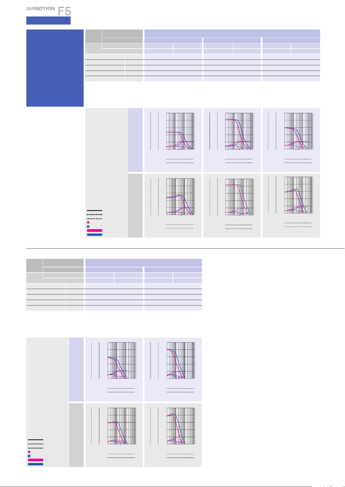
AC100V
Operating current:
1-division fs
2-division fs
0.75A/phase
Pull-out torque
Source current (load applied)
Source current (no load)
Fs:
Maximum self-start
frequency when not loaded
1-division
2-division
AC200V
The data a re measured und er the drive c ondition of o ur company. Th e drive
torque may ver y depending on the acc uracy of cust omer-side e quipment.
□
42
)
)
)
)
)
□
(
mm
1.65
)
)
inch
40mm(1.57inch
0.18(25.49
0.053(0.29
0.28(0.62
10(2.25
35(8.75
)
)
)
)
)
AC inputInput / Output signal standardDC inputStepping motorDimensions
)
Motor flange size
Size
Motor leng th
Single shaft
Set par t
number
Double shaft
Holding torque N・m
Rotor iner tia
Mass(Weight
)
Allowable thrust load N(lbs
Allowable radial l oad
(
Note1)When loa d is applied at 1/ 3 length from output s haft edge .
(
Note 1
(oz・in)
×10-4kg・m2(oz・in2)
kg(lbs
)
N(lbs
□
42
FSF55 4S FPF554S FSF781S FPF781S FSF782S FPF782S FSF783S FPF783S
FSF55 4D FPF554D FSF781D FPF781D FSF782D FPF782D FSF782D FPF783D
)
)
)
AC100V
Operating current:
1-division fs
2-division fs
0.75A/phase
Pull-out torque
Source current (load applied)
Source current (no load)
Fs:
Maximum self-start
frequency when not loaded
1-division
2-division
AC200V
The data a re measured und er the drive c ondition of o ur company. Th e drive torque m ay very dep ending on th e accuracy o f customer-s ide equipm ent.
□
(
mm
1.65
49mm(1.93inch
0.26(36.82
0.065(0.36
0.37(0.81
)
10(2.25
)
35(8.75
)
inch
)
)
)
)
46.5mm(1.83inch
0.6(85.0
0.275(1.50
0.6(1.32
20(4.5
80(18
)
)
)
)
)
)
□
60
□
(
mm
2.36
55mm(2.17inch
0.93(131.7
)
0.4(2.19
)
0.78(1.72
)
20(4.5
)
80(18
)
inch
)
)
87.5mm(3.45inch
1.79(253.5
0.84(4.60
1.36(3.0
20(4.5
80(18
50
5
40
40
4
30
30
3
20
20
2
Torque(N・m )
Torque( lb-in )
Torque( kgf・cm )
10
10
1
0
0
0
40
30
20
Torque( lb-in )
10
0
0.1 110 100
1-division
2-division
Number of rotations (min-1)
50
5
40
4
30
3
20
2
Torque(N・m )
Torque( kgf・cm )
10
1
0
0
1-division
2-division
Pulse rate (kpulse/s)
10 100 1000 2000 3000 5000
0.1 110 100
10 100 1000 2000 3000 5000
Number of rotations (min-1)
)
)
)
)
)
100 1000 2000 3000 5000
Pulse rate (kpulse/s)
100 1000 2000 3000 5000
)
10
9
8
7
6
5
4
3
Source current (A)
2
1
0
10
9
8
7
6
5
4
3
Source current (A)
2
1
0
12
Page 14
5-phase STEPPING SYSTEMS
0
0
4
8
12
16
20
0.1 110 100
0
1
2
3
4
5
6
7
8
9
10
200
160
120
80
40
160
120
80
40
Torque( kgf・cm )
0
Torque( lb-in )
Torque(N・m )
Source current (A)
Pulse rate (kpulse/s)
100 1000 2000 3000 5000
Number of rotations (min-1)
1-division
2-division
10 100 1000 2000 3000 5000
0
0
4
8
12
16
20
0.1 110 100
0
1
2
3
4
5
6
7
8
9
10
200
160
120
80
40
160
120
80
40
Torque( kgf・cm )
0
Torque( lb-in )
Torque(N・m )
Source current (A)
Pulse rate (kpulse/s)
100 1000 2000 3000 5000
Number of rotations (min-1)
1-division
2-division
10 100 1000 2000 3000 5000
0
0
4
8
12
16
20
0.1 110 100
0
1
2
3
4
5
6
7
8
9
10
200
160
120
80
40
160
120
80
40
Torque( kgf・cm )
0
Torque( lb-in )
Torque(N・m )
Source current (A)
Pulse rate (kpulse/s)
100 1000 2000 3000 5000
Number of rotations (min-1)
1-division
2-division
10 100 1000 2000 3000 5000
0
0
2
4
6
8
10
0.1 110 100
0
1
2
3
4
5
6
7
8
9
10
100
80
60
40
20
80
60
40
20
Torque( kgf・cm )
0
Torque( lb-in )
Torque(N・m )
Source current (A)
Pulse rate (kpulse/s)
100 1000 2000 3000 5000
Number of rotations (min-1)
1-division
2-division
10 100 1000 2000 3000 5000
0
0
2
4
6
8
10
0.1 110 100
0
1
2
3
4
5
6
7
8
9
10
100
80
60
40
20
80
60
40
20
Torque( kgf・cm )
0
Torque( lb-in )
Torque(N・m )
Source current (A)
Pulse rate (kpulse/s)
100 1000 2000 3000 5000
Number of rotations (min-1)
1-division
2-division
10 100 1000 2000 3000 5000
0
0
1
2
3
4
5
0.1 110 100
0
1
2
3
4
5
6
7
8
9
10
50
40
30
20
10
40
30
20
10
0
Torque( kgf・cm )
Torque( lb-in )
Torque(N・m )
Source current (A)
Pulse rate (kpulse/s)
100 1000 2000 3000 5000
Number of rotations (min-1)
1-division
2-division
10 100 1000 2000 3000 5000
Torque(N・m )
Source current (A)
Pulse rate (kpulse/s)
1-division
2-division
Number of rotations (min
-1
)
0
1
2
3
4
5
0
1
2
3
4
5
6
7
8
9
10
0.1 110 100
100 1000 2000 30005000
10 100 1000 200030005000
0
50
40
30
20
10
40
30
20
10
Torque( kgf・cm )
0
Torque( lb-in )
0
0
1
2
3
4
5
0.1 110 100
0
1
2
3
4
5
6
7
8
9
10
50
40
30
20
10
40
30
20
10
Torque( kgf・cm )
0
Torque( lb-in )
Torque(N・m )
Source current (A)
Pulse rate (kpulse/s)
100 1000 2000 3000 5000
Number of rotations (min-1)
1-division
2-division
10 100 1000 2000 3000 5000
0
0
1
2
3
4
5
0.11 10 100
0
1
2
3
4
5
6
7
8
9
10
50
40
30
20
10
40
30
20
10
Torque( kgf・cm )
0
Torque( lb-in )
Torque(N・m )
Source current (A)
Pulse rate (kpulse/s)
100 1000 2000 3000 5000
Number of rotations (min-1)
1-division
2-division
10 100 1000 2000 3000 5000
AC input
Specifications
Standard
model
F series driver + F series motor
Motor flange size
Size
Motor leng th
Single shaft
Set par t
number
Double shaft
Holding torque N・m
Rotor iner tia
Mass(Weight
)
Allowable thrust load N(lbs
Allowable radial l oad
(
Note1)When loa d is applied at 1/ 3 length from output s haft edge .
(
)
Note 1
(oz・in)
×10-4kg・m2(oz・in2)
)
kg(lbs
)
)
N(lbs
62.15mm(2.47inch
FSF851S FPF851S FSF852S FPF852S FSF853S FPF853S
FSF851D FPF851D FSF852D FPF852D FSF853D FPF8 53D
2.06(291.7
1.45(7.93
1.5(3.3
60(13.5
220(49.5
AC100V
Operating current:
0.75A/phase
AC200V
The data a re measured und er the drive c ondition of o ur company. Th e drive
torque may ver y depending on the acc uracy of cust omer-side e quipment.
1-division fs
2-division fs
Pull-out torque
Source current (load applied)
Source current (no load)
Fs:
Maximum self-start
frequency when not loaded
1-division
2-division
φ
86
)
)
)
)
)
)
φ
(
mm
3.39
92.2mm(3.63inch
2.5(5.5
60(13.5
)
)
)
)
)
4.02(569. 3
2.9(15.86
220(49.5
inch
)
)
125.85mm(4.95inch
3.5(7.7
60(13.5
220(49.5
)
)
)
)
)
6.17(873.7
4.4(24.06
)
Motor flange size
Size
Motor leng th
Single shaft
Set par t
number
Double shaft
Holding torque N・m
Rotor iner tia
Mass(Weight
)
Allowable thrust load N(lbs
Allowable radial l oad
(
Note1)When loa d is applied at 1/ 3 length from output s haft edge .
(
)
Note 1
(oz・in)
×10-4kg・m2(oz・in2)
)
kg(lbs
)
)
N(lbs
163.3mm(6.43inch
FSF892S FPF892S FSF893S FPF893S
FSF892D FPF892D FSF893D FPF893D
10.8(1529.4
14.6(79.83
7.5(16.5
100(22.5
360(81
φ
)
106
)
)
)
)
φ
(
mm
4.17
)
)
inch
221.3mm(8.71inch
360(81
)
)
)
)
)
16(2265.7
22(120.28
10.5(23.1
100(22.5
)
AC100V
200
20
160
160
16
120
120
Operating current:
1-division fs
2-division fs
13
0.75A/phase
Pull-out torque
Source current (load applied)
Source current (no load)
Fs:
Maximum self-start
frequency when not loaded
1-division
2-division
AC200V
The data a re measured und er the drive c ondition of o ur company. Th e drive torque m ay very dep ending on the a ccuracy o f customer-s ide equipm ent.
12
80
80
8
Torque(N・m )
Torque( lb-in )
Torque( kgf・cm )
40
40
4
0
0
0
0.11 10 100
1-division
2-division
10 100 1000 2000 3000 5000
Number of rotations (min-1)
Pulse rate (kpulse/s)
100 1000 2000 3000 5000
10
9
8
7
6
5
4
3
Source current (A)
2
1
0
Page 15
CE / UL model
0
0
0.1
0.2
0.3
0.4
0.5
0.1 110 100
0
1
2
3
4
5
6
7
8
9
10
5
4
3
2
1
4
3
2
1
0
Torque( kgf・cm )
Torque( lb-in )
Torque(N・m )
Source current (A)
Pulse rate (kpulse/s)
100 1000 2000 3000 5000
Number of rotations (min-1)
1-division
2-division
10 100 1000 2000 3000 5000
0
0
0.1
0.2
0.3
0.4
0.5
0.1 110 100
0
1
2
3
4
5
6
7
8
9
10
5
4
3
2
1
4
3
2
1
0
Torque( kgf・cm )
Torque( lb-in )
Torque(N・m )
Source current (A)
Pulse rate (kpulse/s)
100 1000 2000 3000 5000
Number of rotations (min-1)
1-division
2-division
10 100 1000 2000 3000 5000
0
0
0.1
0.2
0.3
0.4
0.5
0.1 110 100
0
1
2
3
4
5
6
7
8
9
10
5
4
3
2
1
4
3
2
1
0
Torque( kgf・cm )
Torque( lb-in )
Torque(N・m )
Source current (A)
Pulse rate (kpulse/s)
100 1000 2000 3000 5000
Number of rotations (min-1)
1-division
2-division
10 100 1000 2000 3000 5000
0
0
0.1
0.2
0.3
0.4
0.5
0.1 110 100
0
1
2
3
4
5
6
7
8
9
10
5
4
3
2
1
4
3
2
1
0
Torque( kgf・cm )
Torque( lb-in )
Torque(N・m )
Source current (A)
Pulse rate (kpulse/s)
100 1000 2000 3000 5000
Number of rotations (min-1)
1-division
2-division
10 100 1000 2000 3000 5000
0
0
0.1
0.2
0.3
0.4
0.5
0.1 110 100
0
1
2
3
4
5
6
7
8
9
10
5
4
3
2
1
4
3
2
1
0
Torque( kgf・cm )
Torque( lb-in )
Torque(N・m )
Source current (A)
Pulse rate (kpulse/s)
100 1000 2000 3000 5000
Number of rotations (min-1)
1-division
2-division
10 100 1000 2000 3000 5000
0
0
0.1
0.2
0.3
0.4
0.5
0.1 110 100
0
1
2
3
4
5
6
7
8
9
10
5
4
3
2
1
4
3
2
1
0
Torque( kgf・cm )
Torque( lb-in )
Torque(N・m )
Source current (A)
Pulse rate (kpulse/s)
100 1000 2000 3000 5000
Number of rotations (min-1)
1-division
2-division
10 100 1000 2000 3000 5000
0
0
0.2
0.4
0.6
0.8
1.0
0.1 110 100
0
1
2
3
4
5
6
7
8
9
10
10
8
6
4
2
8
6
4
2
0
Torque( kgf・cm )
Torque( lb-in )
Torque(N・m )
Source current (A)
Pulse rate (kpulse/s)
100 1000 2000 3000 5000
Number of rotations (min-1)
1-division
2-division
10 100 1000 2000 3000 5000
0
0
0.2
0.4
0.6
0.8
1.0
0.1 110 100
0
1
2
3
4
5
6
7
8
9
10
10
8
6
4
2
8
6
4
2
0
Torque( kgf・cm )
Torque( lb-in )
Torque(N・m )
Source current (A)
Pulse rate (kpulse/s)
100 1000 2000 3000 5000
Number of rotations (min-1)
1-division
2-division
10 100 1000 2000 3000 5000
0
0
0.4
0.8
1.2
1.6
2.0
0.1 110 100
0
1
2
3
4
5
6
7
8
9
10
20
16
12
8
4
16
12
8
4
0
Torque( kgf・cm )
Torque( lb-in )
Torque(N・m )
Source current (A)
Pulse rate (kpulse/s)
100 1000 2000 3000 5000
Number of rotations (min-1)
1-division
2-division
10 100 1000 2000 3000 5000
0
0
0.4
0.8
1.2
1.6
2.0
0.1 110 100
0
1
2
3
4
5
6
7
8
9
10
20
16
12
8
4
16
12
8
4
0
Torque( kgf・cm )
Torque( lb-in )
Torque(N・m )
Source current (A)
Pulse rate (kpulse/s)
100 1000 2000 3000 5000
Number of rotations (min-1)
1-division
2-division
10 100 1000 2000 3000 5000
0
0
1
2
3
4
5
0.1 110 100
0
1
2
3
4
5
6
7
8
9
10
50
40
30
20
10
40
30
20
10
0
Torque( kgf・cm )
Torque( lb-in )
Torque(N・m )
Source current (A)
Pulse rate (kpulse/s)
100 1000 2000 3000 5000
Number of rotations (min-1)
1-division
2-division
10 100 1000 2000 3000 5000
0
0
1
2
3
4
5
0.1 110 100
0
1
2
3
4
5
6
7
8
9
10
50
40
30
20
10
40
30
20
10
0
Torque( kgf・cm )
Torque( lb-in )
Torque(N・m )
Source current (A)
Pulse rate (kpulse/s)
100 1000 2000 3000 5000
Number of rotations (min-1)
1-division
2-division
10 100 1000 2000 3000 5000
F series driver + M series motor
Motor flange size
φ φ
42
60
86
106
(φ4.17inch)(φ3.39inch)(□2.35inch)(□1.65inch)
Motor flange size
Size
Motor leng th
Single shaft
Set par t
number
Double shaft
Holding torque N・m
Rotor iner tia
Mass(Weight
)
Allowable thrust load N(lbs
Allowable radial l oad
(
Note1)When loa d is applied at 1/ 3 length from output s haft edge .
(
)
Note 1
(oz・in)
×10-4kg・m2(oz・in2)
)
kg(lbs
)
)
N(lbs
31mm(1.22inch
FSM551S FPM551S FSM552S FPM552S
FSM551D FPM551D FSM552D FPM552D
0.13(18.41
0.03(0.16
0.23(0.51
10(2.25
35(8.75
AC100V
Operating current:
1-division fs
2-division fs
0.75A/phase
Pull-out torque
Source current (load applied)
Source current (no load)
Fs:
Maximum self-start
frequency when not loaded
1-division
2-division
AC200V
The data a re measured und er the drive c ondition of o ur company. Th e drive
torque may ver y depending on the acc uracy of cust omer-side e quipment.
□
42
)
)
)
)
)
□
(
mm
1.65
)
)
inch
50.5mm(1.99inch
0.18(25.49
0.053(0.29
0.28(0.62
)
10(2.25
)
35(8.75
)
)
)
)
AC inputInput / Output signal standardDC inputStepping motorDimensions
Motor flange size
Size
Motor leng th
Single shaft
Set par t
number
Double shaft
Holding torque N・m
Rotor iner tia
Mass(Weight
)
Allowable thrust load N(lbs
Allowable radial l oad
(
Note1)When loa d is applied at 1/ 3 length from output s haft edge .
(
Note 1
(oz・in)
×10-4kg・m2(oz・in2)
kg(lbs
)
N(lbs
□
42
FSM554S FPM554S FSM781S FPM781S FSM782S FPM782S FSM783S FPM783S
FSM554D FPM554D FSM781D FPM781D FSM782D FPM782D
)
)
)
□
(
mm
1.65
49mm(1.93inch
0.26(36.82
0.065(0.36
0.37(0.81
)
10(2.25
)
35(8.75
)
inch
)
46.5mm(1.83inch
□
60
)
□
(
mm
2.36
55mm(2.17inch
)
inch
)
87.5mm(3.44inch
)
FSM783D FPM78 3D
1.36(3.0
20(4.5
80(18
)
)
)
)
)
)
)
)
0.6(85.0
0.275(1.50
0.6(1.32
20(4.5
)
80(18
)
)
0.065(9.20
0.016(0.09
)
)
0.2(0.44
3(0.68
34(7.65
)
)
1.79(253.5
0.84(4.59
)
)
)
AC100V
Operating current:
0.75A/phase
Pull-out torque
Source current (load applied)
Source current (no load)
1-division fs
Fs:
2-division fs
1-division
2-division
Maximum self-start
frequency when not loaded
AC200V
The data a re measured und er the drive c ondition of o ur company. Th e drive torque m ay very dep ending on th e accuracy o f customer-s ide equipm ent.
14
Page 16
5-phase STEPPING SYSTEMS
0
0
1
2
3
4
5
0.1 110 100
0
1
2
3
4
5
6
7
8
9
10
50
40
30
20
10
40
30
20
10
0
Torque( kgf・cm )
Torque( lb-in )
Torque(N・m )
Source current (A)
Pulse rate (kpulse/s)
100 1000 2000 3000 5000
Number of rotations (min-1)
1-division
2-division
10 100 1000 2000 3000 5000
Torque(N・m )
Source current (A)
Pulse rate (kpulse/s)
1-division
2-division
Number of rotations (min
-1
)
0
1
2
3
4
5
0
1
2
3
4
5
6
7
8
9
10
0.1 110 100
100 1000 2000 30005000
10 100 1000 200030005000
0
50
40
30
20
10
40
30
20
10
Torque( kgf・cm )
0
Torque( lb-in )
0
0
2
4
6
8
10
0.1 110 100
0
1
2
3
4
5
6
7
8
9
10
100
80
60
40
20
80
60
40
20
0
Torque( kgf・cm )
Torque( lb-in )
Torque(N・m )
Source current (A)
Pulse rate (kpulse/s)
100 1000 2000 3000 5000
Number of rotations (min-1)
1-division
2-division
10 100 1000 2000 3000 5000
0
0
2
4
6
8
10
0.1 110 100
0
1
2
3
4
5
6
7
8
9
10
100
80
60
40
20
80
60
40
20
0
Torque( kgf・cm )
Torque( lb-in )
Torque(N・m )
Source current (A)
Pulse rate (kpulse/s)
100 1000 2000 3000 5000
Number of rotations (min-1)
1-division
2-division
10 100 1000 2000 3000 5000
0
0
4
8
12
16
20
0.1 110 100
0
1
2
3
4
5
6
7
8
9
10
0
200
160
120
80
40
160
120
80
40
Torque( kgf・cm )
Torque( lb-in )
Torque(N・m )
Source current (A)
Pulse rate (kpulse/s)
100 1000 2000 3000 5000
Number of rotations (min-1)
1-division
2-division
10 100 1000 2000 3000 5000
0
0
4
8
12
16
20
0.1 110 100
0
1
2
3
4
5
6
7
8
9
10
200
160
120
80
40
160
120
80
40
Torque( kgf・cm )
0
Torque( lb-in )
Torque(N・m )
Source current (A)
Pulse rate (kpulse/s)
100 1000 2000 3000 5000
Number of rotations (min-1)
1-division
2-division
10 100 1000 2000 3000 5000
0
0
4
8
12
16
20
0.1 110 100
0
1
2
3
4
5
6
7
8
9
10
200
160
120
80
40
160
120
80
40
0
Torque( kgf・cm )
Torque( lb-in )
Torque(N・m )
Source current (A)
Pulse rate (kpulse/s)
100 1000 2000 3000 5000
Number of rotations (min-1)
1-division
2-division
10 100 1000 2000 3000 5000
0
0
4
8
12
16
20
0.1 110 100
0
1
2
3
4
5
6
7
8
9
10
200
160
120
80
40
160
120
80
40
0
Torque( kgf・cm )
Torque( lb-in )
Torque(N・m )
Source current (A)
Pulse rate (kpulse/s)
100 1000 2000 3000 5000
Number of rotations (min-1)
1-division
2-division
10 100 1000 2000 3000 5000
0
0
1
2
3
4
5
0.1 110 100
0
1
2
3
4
5
6
7
8
9
10
0
50
40
30
20
10
40
30
20
10
Torque( kgf・cm )
Torque( lb-in )
Torque(N・m )
Source current (A)
Pulse rate (kpulse/s)
100 1000 2000 3000 5000
Number of rotations (min-1)
1-division
2-division
10 100 1000 2000 3000 5000
0
0
1
2
3
4
5
0.1 110 100
0
1
2
3
4
5
6
7
8
9
10
50
40
30
20
10
40
30
20
10
0
Torque( kgf・cm )
Torque( lb-in )
Torque(N・m )
Source current (A)
Pulse rate (kpulse/s)
100 1000 2000 3000 5000
Number of rotations (min-1)
1-division
2-division
10 100 1000 2000 3000 5000
AC input
Specifications
CE / UL
model
F series driver + M series motor
Motor flange size
Size
Motor leng th
Single shaft
Set par t
number
Double shaft
Holding torque N・m
Rotor iner tia
Mass(Weight
)
Allowable thrust load N(lbs
Allowable radial l oad
(
Note1)When loa d is applied at 1/ 3 length from output s haft edge .
(
)
Note 1
(oz・in)
×10-4kg・m2(oz・in2)
)
kg(lbs
)
)
N(lbs
62.15mm(2.47inch
FSM851S FPM851S FSM852S FPM852S FSM8 53S FPM853S
FSM851D FPM851D FSM852D FPM852D FSM853D FPM853D
2.06(291.7
1.45(7.93
1.5(3.3
60(13.5
220(49.5
AC100V
Operating current:
1-division fs
2-division fs
0.75A/phase
Pull-out torque
Source current (load applied)
Source current (no load)
Fs:
Maximum self-start
frequency when not loaded
1-division
2-division
AC200V
The data a re measured und er the drive c ondition of o ur company. Th e drive
torque may ver y depending on the acc uracy of cust omer-side e quipment.
φ
86
)
)
)
)
)
)
φ
(
mm
3.39
92.2mm(3.63inch
2.5(5.5
60(13.5
)
)
)
)
)
4.02(569. 3
2.9(15.86
220(49.5
inch
)
)
125.85mm(4.95inch
3.5(7.7
60(13.5
)
)
)
)
)
6.17(873.7
4.4(24.06
220(49.5
)
Motor flange size
Size
Motor leng th
Single shaft
Set par t
number
Double shaft
Holding torque N・m
Rotor iner tia
Mass(Weight
)
Allowable thrust load N(lbs
Allowable radial l oad
(
Note1)When loa d is applied at 1/ 3 length from output s haft edge .
(
)
Note 1
(oz・in)
×10-4kg・m2(oz・in2)
)
kg(lbs
)
)
N(lbs
163.3mm(6.43inch
FSM892S FPM892S FSM893S FPM8 93S
FSM892D FPM892D FSM893D FPM893D
10.8(1529.4
14.6(79.83
7.5(16.5
100(22.5
360(81
φ
)
)
106
)
)
)
φ
(
mm
4.17
)
)
inch
221.3mm(8.71inch
360(81
)
)
)
)
)
16(2265.7
22(120.28
10.5(23.1
100(22.5
)
AC100V
1-division fs
2-division fs
Operating current:
0.75A/phase
Pull-out torque
Source current (load applied)
Source current (no load)
Fs:
Maximum self-start
frequency when not loaded
1-division
2-division
AC200V
The data a re measured und er the drive c ondition of o ur company. Th e drive torque m ay very dep ending on th e accuracy o f customer-s ide equipm ent.
15
Page 17
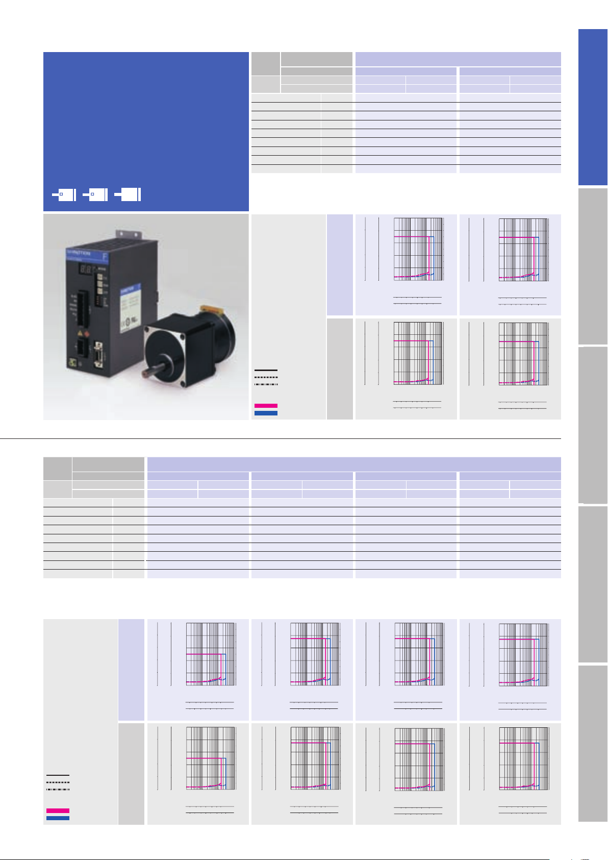
Low-backlash gear
106
φ
(φ4.17inch)
)
5102050 100 200 500
52 102050 100 200
500
0
0
0.1
0.2
0.3
0.4
0.5
0.11 10 100
0
1
2
3
4
5
6
7
8
9
10
5
4
3
2
1
4
3
2
1
0
Torque( kgf・cm )
Torque( lb-in )
Torque(N・m )
Source current (A)
Pulse rate (kpulse/s)
Number of rotations (min
-1
)
1-division
2-division
12 5102050 100
100 250
2510 20 50
250
0
0
0.2
0.4
0.6
0.8
1.0
0.1 110 100
0
1
2
3
4
5
6
7
8
9
10
10
8
6
4
2
8
6
4
2
0
Torque( kgf・cm )
Torque( lb-in )
Torque(N・m )
Source current (A)
Pulse rate (kpulse/s)
1-division
2-division
Number of rotations (min
-1
)
5102050 100 200 500
52 102050 100 200
500
0
0
0.1
0.2
0.3
0.4
0.5
0.1 110 100
0
1
2
3
4
5
6
7
8
9
10
5
4
3
2
1
4
3
2
1
0
Torque( kgf・cm )
Torque( lb-in )
Torque(N・m )
Source current (A)
Pulse rate (kpulse/s)
Number of rotations (min
-1
)
1-division
2-division
12 5102050 100
100 250
2510 20 50
250
0
0
0.2
0.4
0.6
0.8
1.0
0.1 110 100
0
1
2
3
4
5
6
7
8
9
10
10
8
6
4
2
8
6
4
2
0
Torque( kgf・cm )
Torque( lb-in )
Torque(N・m )
Source current (A)
Pulse rate (kpulse/s)
1-division
2-division
Number of rotations (min
-1
)
2510 20 50 100 180
21 5 10 20 50 100
180
0
0
0.4
0.8
1.2
1.6
2.0
0.1 110 100
0
1
2
3
4
5
6
7
8
9
10
20
16
12
8
4
16
12
8
4
0
Torque( kgf・cm )
Torque( lb-in )
Torque(N・m )
Source current (A)
Pulse rate (kpulse/s)
Number of rotations (min
-1
)
1-division
2-division
2510 20 50 100 180
21 5 10 20 50 100
180
0
0
0.4
0.8
1.2
1.6
2.0
0.1 110 100
0
1
2
3
4
5
6
7
8
9
10
20
16
12
8
4
16
12
8
4
0
Torque( kgf・cm )
Torque( lb-in )
Torque(N・m )
Source current (A)
Pulse rate (kpulse/s)
Number of rotations (min
-1
)
1-division
2-division
12 5 509010 20
12 5 509010 20
0
0
0.4
0.8
1.2
1.6
2.0
0.1 110 100
0
1
2
3
4
5
6
7
8
9
10
20
16
12
8
4
16
12
8
4
0
Torque( kgf・cm )
Torque( lb-in )
Torque(N・m )
Source current (A)
Pulse rate (kpulse/s)
Number of rotations (min
-1
)
1-division
2-division
12 5 509010 20
12 5 509010 20
0
0
0.4
0.8
1.2
1.6
2.0
0.1 110 100
0
1
2
3
4
5
6
7
8
9
10
20
16
12
8
4
16
12
8
4
0
Torque( kgf・cm )
Torque( lb-in )
Torque(N・m )
Source current (A)
Pulse rate (kpulse/s)
Number of rotations (min
-1
)
1-division
2-division
2510 20 601
2510 20 601
0
0
0.4
0.8
1.2
1.6
2.0
0.11 10 100
0
1
2
3
4
5
6
7
8
9
10
20
16
12
8
4
16
12
8
4
0
Torque( kgf・cm )
Torque( lb-in )
Torque(N・m )
Source current (A)
Pulse rate (kpulse/s)
Number of rotations (min
-1
)
1-division
2-division
Number of rotations (min-1)
2510 20 601
2510 20 601
0
0
0.4
0.8
1.2
1.6
2.0
0.11 10 100
0
1
2
3
4
5
6
7
8
9
10
20
16
12
8
4
16
12
8
4
0
Torque( kgf・cm )
Torque( lb-in )
Torque(N・m )
Source current (A)
Pulse rate (kpulse/s)
1-division
2-division
12 5102050
12 5102050
Number of rotations (min-1)
0
0
0.4
0.8
1.2
1.6
2.0
0.1 110 100
0
1
2
3
4
5
6
7
8
9
10
20
16
12
8
4
16
12
8
4
0
Torque( kgf・cm )
Torque( lb-in )
Torque(N・m )
Source current (A)
Pulse rate (kpulse/s)
1-division
2-division
12 5102050
12 5102050
0
0
0.4
0.8
1.2
1.6
2.0
0.1 110 100
0
1
2
3
4
5
6
7
8
9
10
20
16
12
8
4
16
12
8
4
0
Torque( kgf・cm )
Torque( lb-in )
Torque(N・m )
Source current (A)
Pulse rate (kpulse/s)
1-division
2-division
Number of rotations (min
-1
)
model
F series driver +
F series motor with low-backlash gear
Motor flange size
42
(□2.35inch)(□1.65inch)
φ
60
86
(φ3.39inch
Motor flange size
Size
Motor + gear length
Single shaft
Set par t
number
Double shaft
Allowable torque N・m
Rotor iner tia
×10-4kg・m2(oz・in2)
□
42
64.5mm(2.54inch
FSF551S-CX3.6 FPF551S-CX3.6 FSF551S-CX7.2 FPF551S-CX7.2
FSF551D-CX3.6 FPF551D-CX3.6 FSF551D-CX7.2 FPF551D-CX7.2
(oz・in)
0.343(48.6
0.03(0.16
)
)
□
(
mm
)
inch
1.65
64.5mm(2.54inch
)
0.686(97.1
0.03(0.16
)
)
)
Basic step angle 0.2 0.1
:
Gear rati o 1
Backlash DEG 0.6 0.4
Allowable speed min
(
)
Weight
Mass
Allowable thrust load N(lbs
Allowable radial load
Directio ns of motor rotat ion and gear o utput shaf t are the same fo r models wit h reductio n ratio 1 : 3.6 , 1 : 7.2, and 1 : 10
opposite f or reductio n ratio 1 : 20, 1 : 3 0, and 1 : 36 .
(
Note1)When loa d is applied at 1/ 3 length from output s haft edge .
(
Note 1
)
kg(lbs
N(lbs
-1
)
)
)
3.6 1:7.2
500 250
)
0.36(0.79
)
15(3.38
)
20(4.5
0.36(0.79
15(3.38
20(4.5
)
)
)
AC100V
Operating current:
0.75A/phase
Allowable torque
Source current (load applied)
Source current (no load)
AC200V
AC inputInput / Output signal standardDC inputStepping motorDimensions
1-division
2-division
The data a re measured und er the drive c ondition of o ur company. Th e drive
torque may ver y depending on the acc uracy of cust omer-side e quipment.
Motor flange size
Size
Motor + gear length
Single shaft
Set par t
number
Double shaft
Allowable torque N・m
Rotor iner tia
×10-4kg・m2(oz・in2)
□
42
64.5mm(2.54inch
)
64.5mm(2.54inch
FSF551S-CX10 FPF551S-CX10 FSF551S- CX20 FPF551S-CX20 FSF551S- CX30 FPF 551S-CX30 FSF551S-CX36 FPF551S-CX36
FSF551D-CX10 FPF551D-CX10 FSF551D-CX20 FPF551D-CX20 FSF551D-CX30 FPF551D-CX30 FSF 551D-CX36 FPF551D- CX36
(oz・in)
0.98(138.8
0.03(0.16
)
)
1.47(208.2
0.03(0.16
)
)
□
(
mm
)
inch
1.65
64.5mm(2.54inch
)
1.47(208.2
0.03(0.16
)
)
)
64.5mm(2.54inch
1.47(208.2
0.03(0.16
Basic step angle 0.072 0.036 0.024 0.02
Gear rati o 1
Backlash DEG 0.35 0.25 0.25 0.25
Allowable speed min
(
Weight
)
(
Note 1
Mass
Allowable thrust load N(lbs
Allowable radial load
Directio ns of motor rotat ion and gear o utput shaf t are the same fo r models wit h reductio n ratio 1 : 3.6 an d 1:7.2, opp osite for redu ction rati o 1 : 10, 1 : 20 and 1 : 30.
(
Note1)When loa d is applied at 1/ 3 length from output s haft edge .
)
kg(lbs
N(lbs
-1
)
)
)
:
10 1:20 1:30 1:36
180 90 60 50
0.36(0.79
15(3.38
20(4.5
)
)
)
0.36(0.79
15(3.38
20(4.5
)
)
)
0.36(0.79
15(3.38
20(4.5
)
)
)
0.36(0.79
15(3.38
20(4.5
AC100V
)
)
)
)
)
)
Operating current:
0.75A/phase
Allowable torque
Source current (load applied)
Source current (no load)
1-division
2-division
AC200V
The data a re measured und er the drive c ondition of o ur company. Th e drive torque m ay very dep ending on th e accuracy o f customer-s ide equipm ent.
16
Page 18
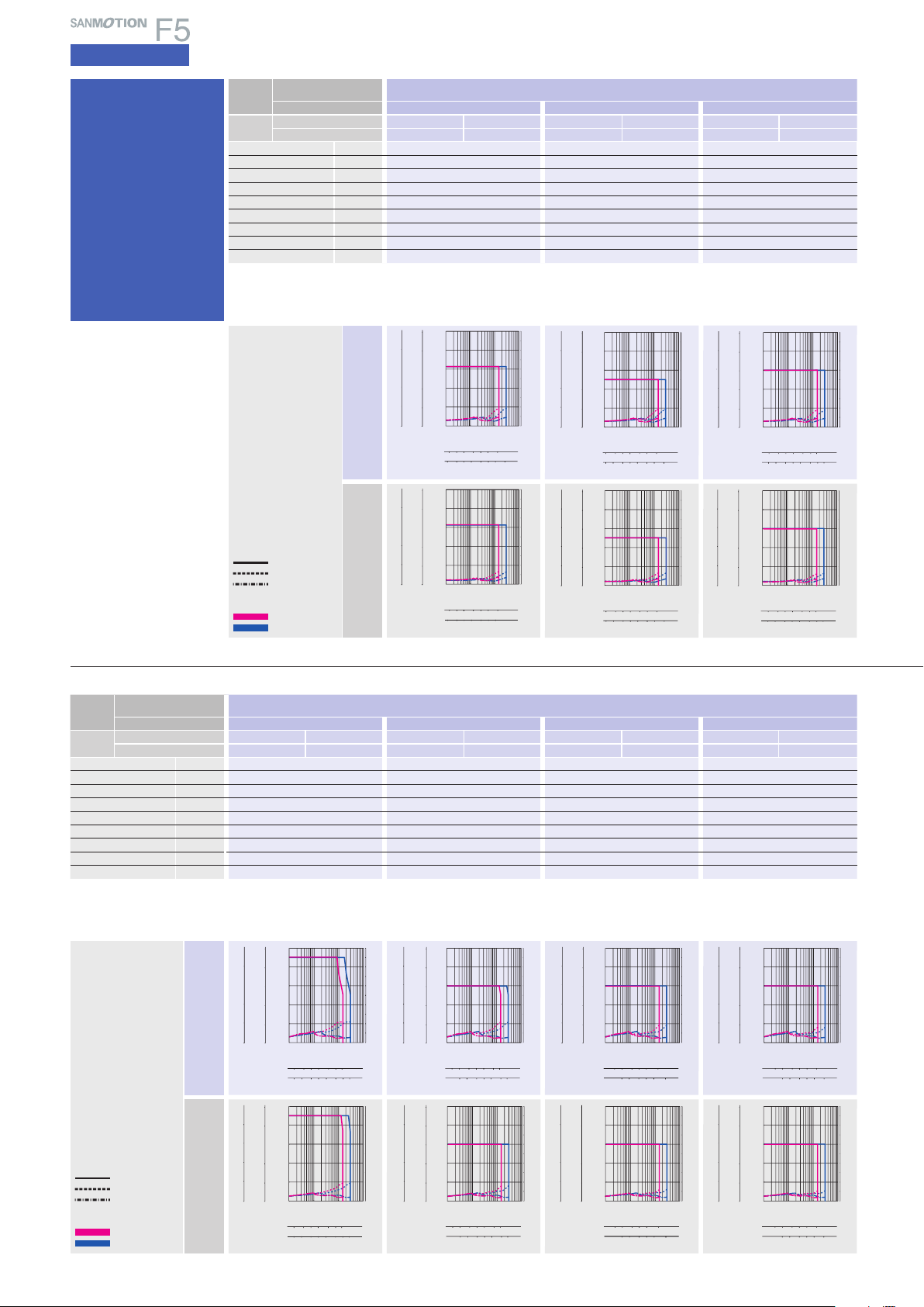
5-phase STEPPING SYSTEMS
12 5102060
12 5102060
0
0
4
8
12
16
20
0.1 110 100
0
1
2
3
4
5
6
7
8
9
10
200
160
120
80
40
160
120
80
40
0
Torque( kgf・cm )
Torque( lb-in )
Torque(N・m )
Source current (A)
Pulse rate (kpulse/s)
1-division
2-division
Number of rotations (min
-1
)
12 5102060
12 5102060
0
0
4
8
12
16
20
0.1 110 100
0
1
2
3
4
5
6
7
8
9
10
200
160
120
80
40
160
120
80
40
0
Torque( kgf・cm )
Torque( lb-in )
Torque(N・m )
Source current (A)
Pulse rate (kpulse/s)
1-division
2-division
Number of rotations (min
-1
)
12 5102050
12 5102050
0
0
4
8
12
16
20
0.1 110 100
0
1
2
3
4
5
6
7
8
9
10
200
160
120
80
40
160
120
80
40
0
Torque( kgf・cm )
Torque( lb-in )
Torque(N・m )
Source current (A)
Pulse rate (kpulse/s)
1-division
2-division
Number of rotations (min
-1
)
12 5102050
12 5102050
0
0
4
8
12
16
20
0.1 110 100
0
1
2
3
4
5
6
7
8
9
10
200
160
120
80
40
160
120
80
40
0
Torque( kgf・cm )
Torque( lb-in )
Torque(N・m )
Source current (A)
Pulse rate (kpulse/s)
1-division
2-division
Number of rotations (min
-1
)
12 5102050 100
2510 20 50 100 180
180
0
0
2
4
6
8
10
0.1 110 100
0
1
2
3
4
5
6
7
8
9
10
100
80
60
40
20
80
60
40
20
0
Torque( kgf・cm )
Torque( lb-in )
Torque(N・m )
Source current (A)
Pulse rate (kpulse/s)
1-division
2-division
Number of rotations (min
-1
)
12 5102050 100
2510 20 50 100 180
180
0
0
2
4
6
8
10
0.1 110 100
0
1
2
3
4
5
6
7
8
9
10
100
80
60
40
20
80
60
40
20
0
Torque( kgf・cm )
Torque( lb-in )
Torque(N・m )
Source current (A)
Pulse rate (kpulse/s)
1-division
2-division
Number of rotations (min
-1
)
12 510205090
12 510205090
0
0
4
8
12
16
20
0.1 110 100
0
1
2
3
4
5
6
7
8
9
10
200
160
120
80
40
160
120
80
40
0
Torque( kgf・cm )
Torque( lb-in )
Torque(N・m )
Source current (A)
Pulse rate (kpulse/s)
1-division
2-division
Number of rotations (min
-1
)
12 510205090
12 510205090
0
0
4
8
12
16
20
0.11 10 100
0
1
2
3
4
5
6
7
8
9
10
200
160
120
80
40
160
120
80
40
0
Torque( kgf・cm )
Torque( lb-in )
Torque(N・m )
Source current (A)
Pulse rate (kpulse/s)
1-division
2-division
Number of rotations (min
-1
)
5102050 10021
10 20 50 100 25052
250
0
0
1
2
3
4
5
0.1 110 100
0
1
2
3
4
5
6
7
8
9
10
50
40
30
20
10
40
30
20
10
0
Torque( kgf・cm )
Torque( lb-in )
Torque(N・m )
Source current (A)
Pulse rate (kpulse/s)
1-division
2-division
Number of rotations (min
-1
)
5102050 10021
10 20 50 100 25052
250
0
0
1
2
3
4
5
0.1 110 100
0
1
2
3
4
5
6
7
8
9
10
50
40
30
20
10
40
30
20
10
0
Torque( kgf・cm )
Torque( lb-in )
Torque(N・m )
Source current (A)
Pulse rate (kpulse/s)
1-division
2-division
Number of rotations (min
-1
)
2510 20 50 100 180
12 5102050 100
180
0
0
1
2
3
4
5
0.11 10 100
0
1
2
3
4
5
6
7
8
9
10
50
40
30
20
10
40
30
20
10
0
Torque( kgf・cm )
Torque( lb-in )
Torque(N・m )
Source current (A)
Pulse rate (kpulse/s)
1-division
2-division
Number of rotations (min
-1
)
2510 20 50 100 180
12 5102050 100
180
0
0
1
2
3
4
5
0.1 110 100
0
1
2
3
4
5
6
7
8
9
10
50
40
30
20
10
40
30
20
10
0
Torque( kgf・cm )
Torque( lb-in )
Torque(N・m )
Source current (A)
Pulse rate (kpulse/s)
1-division
2-division
Number of rotations (min
-1
)
5102050 100 200 500
2510 20 50 100 200
0
0
0.4
0.8
1.2
1.6
2.0
0.1 110 100
0
1
2
3
4
5
6
7
8
9
10
20
16
12
8
4
16
12
8
4
0
Torque( kgf・cm )
Torque( lb-in )
Torque(N・m )
Source current (A)
Pulse rate (kpulse/s)
Number of rotations (min
-1
)
1-division
2-division
500
5102050 100 200 500
2510 20 50 100 200
0
0
0.4
0.8
1.2
1.6
2.0
0.1 110 100
0
1
2
3
4
5
6
7
8
9
10
20
16
12
8
4
16
12
8
4
0
Torque( kgf・cm )
Torque( lb-in )
Torque(N・m )
Source current (A)
Pulse rate (kpulse/s)
Number of rotations (min
-1
)
1-division
2-division
500
AC input
Specifications
Low-backlash
gear model
F series driver +
F series motor with lowbacklash gear
Motor flange size
Size
Motor + gear length
Single shaft
Set par t
number
Double shaft
Allowable torque N・m
Rotor iner tia
×10-4kg・m2(oz・in2)
□
60
92mm(3.62inch
)
FSF781S-CX3.6 FPF781S-CX3.6 FSF781S- CX7.2 FPF781S-CX7.2 FSF781S-CX10 FPF781S-CX10
FSF781D-CX3.6 FPF781D-CX3.6 FSF781D-CX7.2 FPF781D-CX7.2 FSF781D-CX10 FPF781D-CX10
(oz・in)
1.25(177.0
0.275(1.5
)
)
□
(
mm
2.36
92mm(3.62inch
2.5(354.0
)
0.275(1.5
)
inch
)
)
92mm(3.62inch
3(424.8
0.275(1.5
Basic step angle 0.2 0.1 0.072
Gear rati o 1
Backlash DEG 0.55 0.25 0.25
Allowable speed min
(
Weight
)
(
Note 1
Mass
Allowable thrust load N(lbs
Allowable radial load
Directio ns of motor rotat ion and gear ou tput shaf t are the same for m odels with r eduction r atio 1 : 3.6 and 1:7.2, oppo site for reduc tion ratio 1 : 10,
1 : 20 and 1 : 30 .
(
Note1)When loa d is applied at 1/ 3 length from output s haft edge .
)
kg(lbs
N(lbs
-1
)
)
)
:
3.6 1:7.2 1:10
500 250 180
0.97(2.13
30(6.75
100(22.5
)
)
)
0.97(2.13
30(6.75
100(22.5
)
)
)
0.97(2.13
30(6.75
100(22.5
AC100V
Operating current:
0.75A/phase
Allowable torque
Source current (load applied)
Source current (no load)
AC200V
)
)
)
)
)
)
1-division
2-division
The data a re measured und er the drive c ondition of o ur company. Th e drive
torque may ver y depending on the acc uracy of cust omer-side e quipment.
Motor flange size
Size
Motor + gear length
Single shaft
Set par t
number
Double shaft
Allowable torque N・m
Rotor iner tia
×10-4kg・m2(oz・in2)
φ
127.3mm(5.01inch
)
127.3mm(5.01inch
FSF851S-CX10 FPF851S- CX10 FSF851S- CX20 FPF851S-CX 20 FSF851S-CX30 FPF851S-CX30 FSF851S-CX36 FPF851S-CX36
FSF851D-CX10 FPF8 51D-CX10 FSF851D-CX20 FPF851D-CX20 FSF851D-CX30 FPF851D-CX30 FSF851D-CX36 FPF851D-CX36
(oz・in)
9(1274.5
1.45(7.93
)
)
12(1699.3
1.45(7.93
)
)
86
φ
(
mm
3.39
)
)
inch
127.3mm(5.01inch
1.45(7.93
)
)
12(1699.3
)
127.3mm(5.01inch
12(1699.3
1.45(7.93
Basic step angle 0.072 0.036 0.024 0.02
Gear rati o 1
Backlash DEG 0.22 0.15 0.15 0.15
Allowable speed min
(
Weight
)
(
Note 1
Mass
Allowable thrust load N(lbs
Allowable radial load
Directio ns of motor rotat ion and gear o utput shaf t are the same fo r models wit h reductio n ratio 1 : 3.6 an d 1:7.2, opp osite for redu ction rati o 1 : 10, 1 : 20 and 1 : 30.
(
Note1)When loa d is applied at 1/ 3 length from output s haft edge .
)
kg(lbs
N(lbs
-1
)
)
)
:
10 1:20 1:30 1:36
180 90 60 50
2.7(5.94
60(13.5
300(67.5
)
)
)
2.7(5.94
60(13.5
300(67.5
)
)
)
2.7(5.94
60(13.5
300(67.5
)
)
)
2.7(5.94
60(13.5
300(67.5
AC100V
)
)
)
)
)
)
Operating current:
0.75A/phase
17
Allowable torque
Source current (load applied)
Source current (no load)
1-division
2-division
AC200V
The data a re measured und er the drive c ondition of o ur company. Th e drive torque m ay very dep ending on th e accuracy o f customer-s ide equipm ent.
Page 19
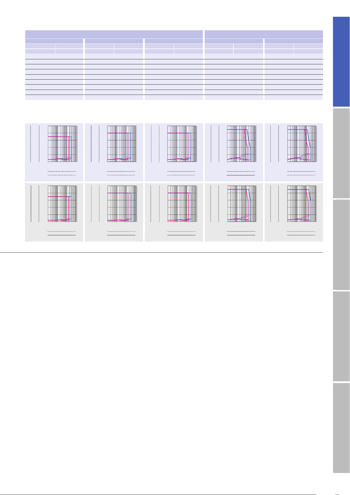
5102050 100 200 500
2510 20 50 100 200
500
0
0
1
2
3
4
5
0.11 10 100
0
1
2
3
4
5
6
7
8
9
10
50
40
30
20
10
40
30
20
10
0
Torque( kgf・cm )
Torque( lb-in )
Torque(N・m )
Source current (A)
Pulse rate (kpulse/s)
1-division
2-division
Number of rotations (min
-1
)
5102050 100 200 500
2510 20 50 100 200
500
0
0
1
2
3
4
5
0.1 110 100
0
1
2
3
4
5
6
7
8
9
10
50
40
30
20
10
40
30
20
10
0
Torque( kgf・cm )
Torque( lb-in )
Torque(N・m )
Source current (A)
Pulse rate (kpulse/s)
1-division
2-division
Number of rotations (min
-1
)
12 5102050 100
100 250
2510 20 50
250
0
0.1 110 100
0
1
2
3
4
5
6
7
8
9
10
100
80
60
40
20
80
60
40
20
0 0
10
8
6
4
2
Torque( kgf・cm )
Torque( lb-in )
Torque(N・m )
Source current (A)
Pulse rate (kpulse/s)
1-division
2-division
Number of rotations (min
-1
)
12 5102050 100
100 250
2510 20 50
250
0
0.1 110 100
0
1
2
3
4
5
6
7
8
9
10
100
80
60
40
20
80
60
40
20
0 0
10
8
6
4
2
Torque( kgf・cm )
Torque( lb-in )
Torque(N・m )
Source current (A)
Pulse rate (kpulse/s)
1-division
2-division
Number of rotations (min
-1
)
12 5102060
12 5102060
0
0
1
2
3
4
5
0.11 10 100
0
1
2
3
4
5
6
7
8
9
10
50
40
30
20
10
40
30
20
10
0
Torque( kgf・cm )
Torque( lb-in )
Torque(N・m )
Source current (A)
Pulse rate (kpulse/s)
1-division
2-division
Number of rotations (min
-1
)
12 5102060
12 5102060
0
0
1
2
3
4
5
0.1 110 100
0
1
2
3
4
5
6
7
8
9
10
50
40
30
20
10
40
30
20
10
0
Torque( kgf・cm )
Torque( lb-in )
Torque(N・m )
Source current (A)
Pulse rate (kpulse/s)
1-division
2-division
Number of rotations (min
-1
)
12 5102050
12 5102050
0
0
1
2
3
4
5
0.1 110 100
0
1
2
3
4
5
6
7
8
9
10
50
40
30
20
10
40
30
20
10
0
Torque( kgf・cm )
Torque( lb-in )
Torque(N・m )
Source current (A)
Pulse rate (kpulse/s)
1-division
2-division
Number of rotations (min
-1
)
12 5102050
12 5102050
0
0
1
2
3
4
5
0.1 110 100
0
1
2
3
4
5
6
7
8
9
10
50
40
30
20
10
40
30
20
10
0
Torque( kgf・cm )
Torque( lb-in )
Torque(N・m )
Source current (A)
Pulse rate (kpulse/s)
1-division
2-division
Number of rotations (min
-1
)
12 510205090
12 510205090
0
0
1
2
3
4
5
0.1 110 100
0
1
2
3
4
5
6
7
8
9
10
50
40
30
20
10
40
30
20
10
0
Torque( kgf・cm )
Torque( lb-in )
Torque(N・m )
Source current (A)
Pulse rate (kpulse/s)
1-division
2-division
Number of rotations (min
-1
)
12 510205090
12 510205090
0
0
1
2
3
4
5
0.1 110 100
0
1
2
3
4
5
6
7
8
9
10
50
40
30
20
10
40
30
20
10
0
Torque( kgf・cm )
Torque( lb-in )
Torque(N・m )
Source current (A)
Pulse rate (kpulse/s)
1-division
2-division
Number of rotations (min
-1
)
92mm(3.62inch
□
60
)
□
(
mm
2.36
92mm(3.62inch
)
inch
)
92mm(3.62inch
)
127.3mm(5.01inch
φ
86
φ
(
mm
3.39
)
)
inch
127.3mm(5.01inch
)
FSF781S-CX20 FPF781S-CX20 FSF781S-CX30 FPF781S-CX30 FSF781S-CX36 FPF781S-CX36 FSF851S-CX3.6 FPF851S-CX3.6 FSF8 51S-CX7.2 FPF851S-CX7.2
FSF781D-CX20 FPF781D- CX20 FSF781D-CX30 FPF781D- CX30 FSF781D-CX36 FPF781D-CX36 FSF8 51D-CX3.6 FPF851D- CX3.6 FSF851D-CX7.2 FPF851D-CX7.2
3.5(495.6
0.275(1.5
)
)
4(566.4
0.275(1.5
)
)
4(566.4
0.275(1.5
)
)
4.5(637.2
1.45(7.93
)
)
9(1274.5
1.45(7.93
)
)
0.036 0.024 0.02 0.2 0.1
:
20 1:30 1:36 1:3.6 1:7.2
1
0.17 0.17 0.17 0.35 0.22
90 60 50 500 250
(
2.13
0.97
30(6.75
100(22.5
)
)
)
0.97(2.13
30(6.75
100(22.5
)
)
)
0.97(2.13
30(6.75
100(22.5
)
)
)
2.7(5.94
60(13.5
300(67.5
)
)
)
2.7(5.94
60(13.5
300(67.5
)
)
)
AC inputInput / Output signal standardDC inputStepping motorDimensions
18
Page 20
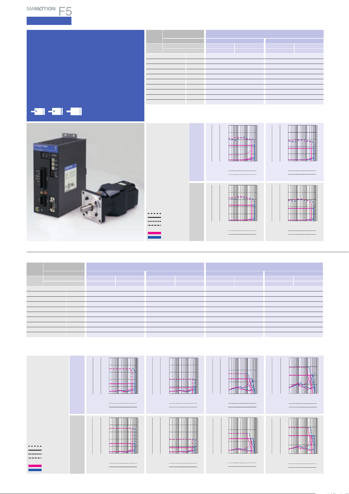
5-phase STEPPING SYSTEMS
12510 20 35
12 5102035
0
0.1 110 100
0
1
2
3
480
20
40
60
800
200
400
600
0
200
400
600
0
Torque( kgf・cm )
Torque( lb-in )
Torque(N・m )
Source current (A)
Pulse rate (kpulse/s)
Number of rotations (min
-1
)
1-division
2-division
12510 20 35
12 5102035
0
0.1 110 100
0
1
2
3
4
40
60
80
20
400
600
800
200
400
600
200
0 0
Torque( kgf・cm )
Torque( lb-in )
Torque(N・m )
Source current (A)
Pulse rate (kpulse/s)
Number of rotations (min
-1
)
1-division
2-division
1 2 5 10 20 50 116
1 2 5 10 20 50 116
0
0.1 110 100
0
1
2
3
4
5
6
7
8
9
10
50
40
30
20
10
40
30
20
10
0 0
5
4
3
2
1
Torque( kgf・cm )
Torque( lb-in )
Torque(N・m )
Source current (A)
Pulse rate (kpulse/s)
Number of rotations (min
-1
)
1-division
2-division
1 2 5 10 20 50 116
1 2 5 10 20 50 116
0
0.1 110 100
0
1
2
3
4
5
6
7
8
9
10
50
40
30
20
10
40
30
20
10
0 0
5
4
3
2
1
Torque( kgf・cm )
Torque( lb-in )
Torque(N・m )
Source current (A)
Pulse rate (kpulse/s)
Number of rotations (min
-1
)
1-division
2-division
12 5102070
12 5102070
0
0
2
4
6
8
10
0.11 10 100
0
1
2
3
4
5
6
7
8
9
10
100
80
60
40
20
80
60
40
20
0
Torque( kgf・cm )
Torque( lb-in )
Torque(N・m )
Source current (A)
Pulse rate (kpulse/s)
Number of rotations (min
-1
)
1-division
2-division
12 5102070
12 5102070
0
0
2
4
6
8
10
0.1 110 100
0
1
2
3
4
5
6
7
8
9
10
100
80
60
40
20
80
60
40
20
0
Torque( kgf・cm )
Torque( lb-in )
Torque(N・m )
Source current (A)
Pulse rate (kpulse/s)
1-division
2-division
Number of rotations (min
-1
)
510201
2
70
510201
2
70
0
0.11 10 100
0
1
2
3
4
5
6
7
8
9
10
200
160
120
80
40
160
120
80
40
0 0
20
16
12
8
4
Torque( kgf・cm )
Torque( lb-in )
Torque(N・m )
Source current (A)
Pulse rate (kpulse/s)
Number of rotations (min
-1
)
1-division
2-division
510201
2
70
510201
2
70
0
0.1 110 100
0
1
2
3
4
5
6
7
8
9
10
200
160
120
80
40
160
120
80
40
0 0
20
16
12
8
4
Torque( kgf・cm )
Torque( lb-in )
Torque(N・m )
Source current (A)
Pulse rate (kpulse/s)
Number of rotations (min
-1
)
1-division
2-division
1
51020235
510201
2
35
0
0.1 110 100
0
1
2
3
4
5
6
7
8
9
10
500
400
300
200
100
400
300
200
100
0 0
50
40
30
20
10
Torque( kgf・cm )
Torque( lb-in )
Torque(N・m )
Source current (A)
Pulse rate (kpulse/s)
Number of rotations (min
-1
)
1-division
2-division
1
51020235
510201
2
35
0
0.1 110 100
0
1
2
3
4
5
6
7
8
9
10
500
400
300
200
100
400
300
200
100
0 0
50
40
30
20
10
Torque( kgf・cm )
Torque( lb-in )
Torque(N・m )
Source current (A)
Pulse rate (kpulse/s)
Number of rotations (min
-1
)
1-division
2-division
1
2
5102070
1
2
5102070
0
0.1 110 100
0
1
2
3
4
5
660
40
20
Torque( kgf・cm )
Torque( lb-in )
Torque(N・m )
Source current (A)
Pulse rate (kpulse/s)
Number of rotations (min
-1
)
1-division
2-division
0
600
400
200
0
400
200
1
2
5102070
1
2
5102070
0
0.1 110 100
0
1
2
3
4
5
660
40
20
600
400
200
0
Torque( kgf・cm )
Torque( lb-in )
Torque(N・m )
Source current (A)
Pulse rate (kpulse/s)
Number of rotations (min
-1
)
1-division
2-division
400
200
0
AC input
Specifications
Harmonic gear model
F series driver +
F series motor with harmonic gear
Motor flange size
φ
42
60
86
(φ3.39inch)(□2.35inch)(□1.65inch)
Motor flange size
Size
Motor + gear length
Single shaft
Set par t
number
Double shaft
Allowable torque N・m
Momentary allow able torque
Rotor iner tia
N・m
×10-4kg・m2(oz・in2)
□
42
73.5mm(2.89inch
FSF551S-HX30 FPF551S-HX30 FSF551S-HX50 FPF551S-HX50
FSF551D-HX30 FPF551D-HX30 FSF551D-HX50 FPF551D-HX50
(oz・in)
(oz・in)
0.042(0.23
2.2(311.5
4.5(637.3
)
)
)
□
(
mm
1.65
)
)
inch
73.5mm(2.89inch
3.5(495.6
8.3(1175.4
0.042(0.23
Basic step angle 0.024 0.0144
Gear ratio 1
Hysteresis loss Minute 3.6 2.4
Allowable speed min
(
)
Weight
Mass
Allowable thrust load N(lbs
Allowable radial load
Directio ns of gear out put shaft are t he opposi te.
(
Note1)When loa d is applied at 1/ 3 length from output s haft edge .
(
Note 1
)
kg(lbs
N(lbs
-1
)
)
)
:30 1:50
116 70
0.42(0.92
1150(258.75
209(46.98
)
)
)
0.42(0.92
1150(258.75
209(46.98
AC100V
Operating current:
0.75A/phase
Momentary allowable torque
Allowable torque
Source current (load applied)
Source current (no load)
1-division
2-division
AC200V
The data a re measured und er the drive c ondition of o ur company. Th e drive
torque may ver y depending on the acc uracy of cust omer-side e quipment.
)
)
)
)
)
)
)
Motor flange size
Size
Motor + gear length
Single shaft
Set par t
number
Double shaft
Allowable torque N・m
Momentary allow able torque
Rotor iner tia
N・m
×10-4kg・m2(oz・in2)
□
60
113.5mm(4.47inch
FSF781S-HX50 FPF781S-HX50 FSF781S-HX100 FPF781S-HX100 FSF851S- HX50 FPF851S-HX50 FSF851S-HX100 FPF851S- HX100
FSF781D-HX50 FPF781D- HX50 FSF781D-HX100 FPF781D-HX100 FSF851D-HX50 FPF851D-HX50 FSF851D-HX100 FPF851D-HX100
(oz・in)
(oz・in)
14(1982.6
0.31(1.695
5.5(778.8
)
)
)
□
(
mm
2.36
)
)
inch
113.5mm(4.47inch
)
8(1132.9
20(2832.2
0.31(1.695
)
)
)
113.5mm(4.47inch
25(3540.2
34(4814.8
1.65(9.021
φ
86
mm
(
φ
3.39
)
)
)
)
Basic step angle 0.0144 0.0072 0.0144 0.0072
Gear rati o 1
Lost motion Minute
Allowable speed min
(
Weight
)
kg(lbs
(
)
Note 1
Mass
Allowable thrust load N(lbs
Allowable radial load
Directio ns of gear out put shaft are t he opposi te.
(
Note1)When loa d is applied at 1/ 3 length from output sh aft edge .
0.4 to 3±0.028N・m(3.965oz・in)0.4 to 1.5±0.4N・m(56.6 45oz・in)0.4 to 3±1N・m(141.612oz・in)0.4 to 3±1.2N・m(169.934oz・in
-1
)
)
)
N(lbs
:
50 1:100 1:50 1:100
70 35 70 35
1.2(2.64
400(90
360(81
)
)
)
1.2(2.64
400(90
360(81
)
)
)
1350(303.5
3.3(7.26
1400(315
)
)
)
AC100V
Operating current:
19
0.75A/phase
Momentary allowable torque
Allowable torque
Source current (load applied)
Source current (no load)
1-division
2-division
AC200V
The data a re measured und er the drive c ondition of o ur company. Th e drive torque m ay very dep ending on th e accuracy o f customer-s ide equipm ent.
)
inch
113.5mm(4.47inch
3.3(7.26
)
)
)
)
)
)
40(5664.3
59(8355.1
1.65(9.021
1400(315
1380(310.5
)
)
Page 21
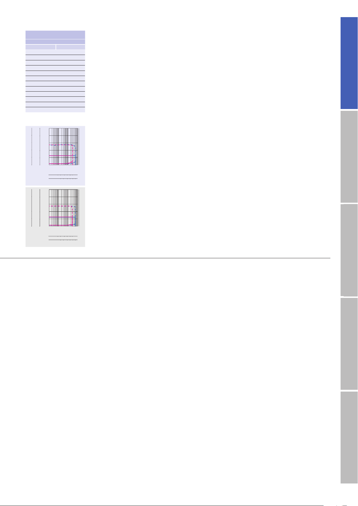
12 5102035
12 5102035
0
0
4
8
12
16
20
0.1 110 100
0
1
2
3
4
5
6
7
8
9
10
200
160
120
80
40
160
120
80
40
0
Torque( kgf・cm )
Torque( lb-in )
Torque(N・m )
Source current (A)
Pulse rate (kpulse/s)
Number of rotations (min
-1
)
1-division
2-division
12 5102035
12 5102035
0
0
4
8
12
16
20
0.1 110 100
0
1
2
3
4
5
6
7
8
9
10
200
160
120
80
40
160
120
80
40
0
Torque( kgf・cm )
Torque( lb-in )
Torque(N・m )
Source current (A)
Pulse rate (kpulse/s)
Number of rotations (min
-1
)
1-division
2-division
□
42
□
(
mm
1.65
73.5mm(2.89inch
inch
)
)
FSF551S-HX100 FPF551S-HX100
FSF551D-HX100
FPF551D-HX100
(
)
708.1
5
)
11(1557.7
0.042(0.23
)
0.0072
:
100
1
2.4
35
(
)
0.92
0.42
1150(258.75
209(46.98
)
)
AC inputInput / Output signal standardDC inputStepping motorDimensions
20
Page 22
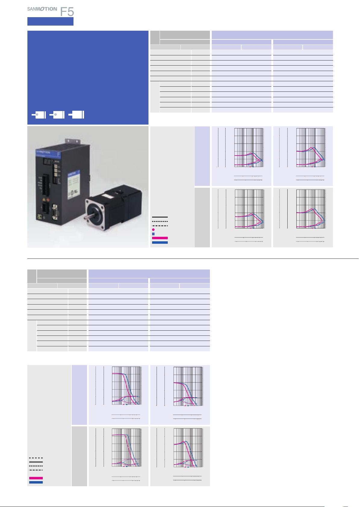
5-phase STEPPING SYSTEMS
0
0
1
2
3
4
5
0.1 110 100
0
1
2
3
4
5
6
7
8
9
10
50
40
30
20
10
40
30
20
10
0
Torque( kgf・cm )
Torque( lb-in )
Torque(N・m )
Source current (A)
Pulse rate (kpulse/s)
100 1000 2000 3000 5000
Number of rotations (min-1)
1-division
2-division
10 100 1000 2000 3000 5000
Torque(N・m )
Source current (A)
Pulse rate (kpulse/s)
1-division
2-division
Number of rotations (min
-1
)
0
1
2
3
4
5
0
1
2
3
4
5
6
7
8
9
10
0.1 110 100
100 1000 2000 30005000
10 100 1000 200030005000
0
50
40
30
20
10
40
30
20
10
Torque( kgf・cm )
0
Torque( lb-in )
100 1000 2000 3000 5000
100 100 1000 20003000 5000
0
0
2
4
6
8
10
0.1 110 100
0
1
2
3
4
5
6
7
8
9
10
100
80
60
40
20
80
60
40
20
0
Torque( kgf・cm )
Torque( lb-in )
Torque(N・m )
Source current (A)
Pulse rate (kpulse/s)
1-division
2-division
Number of rotations (min
-1
)
100 1000 2000 3000 5000
100 100 1000 20003000 5000
0
0
2
4
6
8
10
0.1 110 100
0
1
2
3
4
5
6
7
8
9
10
100
80
60
40
20
80
60
40
20
0
Torque( kgf・cm )
Torque( lb-in )
Torque(N・m )
Source current (A)
Pulse rate (kpulse/s)
1-division
2-division
Number of rotations (min-1)
100 1000 2000 3000 5000
10 100 1000 2000 3000 5000
0
0.1
0.2
0.3
0.4
0.5
0
1
2
3
4
1
2
3
4
5
0
0.11 10 100
0
1
2
3
4
5
6
7
8
9
10
Torque( kgf・cm )
Torque( lb-in )
Torque(N・m )
Source current (A)
Pulse rate (kpulse/s)
1-division
2-division
Number of rotations (min
-1
)
100 1000 2000 3000 5000
10 100 1000 2000 3000 5000
0
0.1
0.2
0.3
0.4
0.5
0
1
2
3
4
1
2
3
4
5
0
0.1 110 100
0
1
2
3
4
5
6
7
8
9
10
Torque( kgf・cm )
Torque( lb-in )
Torque(N・m )
Source current (A)
Pulse rate (kpulse/s)
1-division
2-division
Number of rotations (min
-1
)
100 1000 2000 3000 5000
10 100 1000 2000 3000 5000
0
0.1
0.2
0.3
0.4
0.5
0
1
2
3
4
1
2
3
4
5
0
0.1 110 100
0
1
2
3
4
5
6
7
8
9
10
Torque( kgf・cm )
Torque( lb-in )
Torque(N・m )
Source current (A)
Pulse rate (kpulse/s)
1-division
2-division
Number of rotations (min
-1
)
100 1000 2000 3000 5000
10 100 1000 2000 3000 5000
0
0.1
0.2
0.3
0.4
0.5
0
1
2
3
4
1
2
3
4
5
0
0.1 110 100
0
1
2
3
4
5
6
7
8
9
10
Torque( kgf・cm )
Torque( lb-in )
Torque(N・m )
Source current (A)
Pulse rate (kpulse/s)
1-division
2-division
Number of rotations (min
-1
)
106
φ
(φ4.17inch)
)
AC input
Specifications
Electromagnetic brake model
F series driver + F series motor with
electromagnetic brake
Motor flange size
φ
42
60
(□2.35inch)(□1.65inch)
86
(φ3.39inch
Motor flange size
Size
Motor + brake length
Set par t number
Holding torque N・m
Rotor iner tia
Mass(Weight
Allowable thrust load N(lbs
Allowable radial l oad
Single shaft
)
(
Note 1
(oz・in)
×10-4kg・m2(oz・in2)
kg(lbs
)
N(lbs
□
42
64.5mm(2.54inch
FSF551S-XB FPF551S-XB FSF552S-XB FPF552S-XB
)
0.13(8.4
0.04 5(0.246
)
)
)
0.38(0.84
10(2.25
35(8.75
)
)
)
)
□
(
mm
1.65
)
)
inch
70.5mm(2.78inch
0.18(25.49
0.068(0.372
0.43(0.95
)
10(2.25
)
35(8.75
)
)
)
)
Brake type No excitation actuating type No excitation ac tuating type
Power supply input
Excitation current
Power consumption
Static fiction torque
Brake operating time
Electromagnetic
brake
Brake releas e time
(
Note1)When loa d is applied at 1/ 3 length from output s haft edge .
V DC24V±5% DC24V±5%
A 0.08 0.08
W 2 2
N・m
(oz・in)
0.22(31.15
)
0.22(31.15
ms 30 30
ms 20 20
)
AC100V
Operating current:
0.75A/phase
1-division fs
2-division fs
Pull-out torque
Source current (load applied)
Source current (no load)
Fs:
Maximum self-start
frequency when not loaded
1-division
2-division
AC200V
The data a re measured und er the drive c ondition of o ur company. Th e drive
torque may ver y depending on the acc uracy of cust omer-side e quipment.
Motor flange size
Size
Motor + brake length
Set par t number
Holding torque N・m
Rotor iner tia
Mass(Weight
Allowable thrust load N(lbs
Allowable radial l oad
Single shaft
)
(
Note 1
(oz・in)
×10-4kg・m2(oz・in2)
kg(lbs
)
N(lbs
φ
86
146.8mm(5.78mm
FSF852S-XB FPF852S-XB FSF853S -XB FPF853S-XB
4.5(9.9
60(13.5
)
)
)
)
)
4.02(569. 3
3.69(20.175
)
)
)
220(49.5
φ
(
mm
3.39
)
)
inch
180.4mm(7.10mm
6.17(873.7
5.19(28.376
)
5.5(12.1
)
60(13.5
)
220(49.5
)
)
)
Brake type No excitation actuating t ype No excitation actuating type
Power supply input
Excitation current
Power consumption
Static fiction torque
Brake operating time
Electromagnetic
brake
Brake releas e time
(
Note1)When loa d is applied at 1/ 3 length from output s haft edge .
V DC24V±5% DC24V±5%
A 0.42 0.42
W 10 10
N・m
(oz・in)
4(566.45
)
4(566.45
ms 50 50
ms 20 20
)
AC100V
Operating current:
21
0.75A/phase
Momentary allowable torque
Allowable torque
Source current (load applied)
Source current (no load)
1-division
2-division
AC200V
The data a re measured und er the drive c ondition of o ur company. Th e drive
torque may ver y depending on the acc uracy of cust omer-side e quipment.
Page 23

100 1000 2000 3000 5000
100 1000 20003000 500010
0
0
1
2
3
4
5
0.1 110 100
0
1
2
3
4
5
6
7
8
9
10
50
40
30
20
10
40
30
20
10
0
Torque( kgf・cm )
Torque( lb-in )
Torque(N・m )
Source current (A)
Pulse rate (kpulse/s)
1-division
2-division
Number of rotations (min
-1
)
100 1000 2000 3000 5000
100 1000 20003000 500010
0
0
1
2
3
4
5
0.11 10 100
0
1
2
3
4
5
6
7
8
9
10
50
40
30
20
10
40
30
20
10
0
Torque( kgf・cm )
Torque( lb-in )
Torque(N・m )
Source current (A)
Pulse rate (kpulse/s)
1-division
2-division
Number of rotations (min
-1
)
100 1000 2000 3000 5000
10 100 1000 2000 3000 5000
0
0.1
0.2
0.3
0.4
0.5
0
1
2
3
4
1
2
3
4
5
0
0.1 110 100
0
1
2
3
4
5
6
7
8
9
10
Torque( kgf・cm )
Torque( lb-in )
Torque(N・m )
Source current (A)
Pulse rate (kpulse/s)
1-division
2-division
Number of rotations (min
-1
)
100 1000 2000 3000 5000
10 100 1000 2000 3000 5000
0
0.1
0.2
0.3
0.4
0.5
0
1
2
3
4
1
2
3
4
5
0
0.11 10 100
0
1
2
3
4
5
6
7
8
9
10
Torque( kgf・cm )
Torque( lb-in )
Torque(N・m )
Source current (A)
Pulse rate (kpulse/s)
1-division
2-division
Number of rotations (min
-1
)
100 1000 20003000 5000
10 100 1000 20003000 5000
0
0
0.2
0.4
0.6
0.8
1.0
0.1 110 100
0
1
2
3
4
5
6
7
8
9
10
10
8
6
4
2
8
6
4
2
0
Torque( kgf・cm )
Torque( lb-in )
Torque(N・m )
Source current (A)
Pulse rate (kpulse/s)
1-division
2-division
Number of rotations (min
-1
)
100 1000 20003000 5000
10 100 1000 20003000 5000
0
0
0.2
0.4
0.6
0.8
1.0
0.11 10 100
0
1
2
3
4
5
6
7
8
9
10
10
8
6
4
2
8
6
4
2
0
Torque( kgf・cm )
Torque( lb-in )
Torque(N・m )
Source current (A)
Pulse rate (kpulse/s)
1-division
2-division
Number of rotations (min
-1
)
100 1000 2000 3000 5000
10 100 1000 2000 30005000
0
0
0.4
0.8
1.2
1.6
2.0
0.1 110 100
0
1
2
3
4
5
6
7
8
9
10
20
16
12
8
4
16
12
8
4
0
Torque( kgf・cm )
Torque( lb-in )
Torque(N・m )
Source current (A)
Pulse rate (kpulse/s)
Number of rotations (min
-1
)
1-division
2-division
100 1000 2000 3000 5000
10 100 1000 2000 30005000
0
0
0.4
0.8
1.2
1.6
2.0
0.11 10 100
0
1
2
3
4
5
6
7
8
9
10
20
16
12
8
4
16
12
8
4
0
Torque( kgf・cm )
Torque( lb-in )
Torque(N・m )
Source current (A)
Pulse rate (kpulse/s)
Number of rotations (min
-1
)
1-division
2-division
100 1000 2000 3000 5000
100 1000 20003000 500010
0
0
1
2
3
4
5
0.1 110 100
0
1
2
3
4
5
6
7
8
9
10
50
40
30
20
10
40
30
20
10
0
Torque( kgf・cm )
Torque( lb-in )
Torque(N・m )
Source current (A)
Pulse rate (kpulse/s)
1-division
2-division
Number of rotations (min
-1
)
100 1000 2000 3000 5000
100 1000 20003000 500010
0
0
1
2
3
4
5
0.1 110 100
0
1
2
3
4
5
6
7
8
9
10
50
40
30
20
10
40
30
20
10
0
Torque( kgf・cm )
Torque( lb-in )
Torque(N・m )
Source current (A)
Pulse rate (kpulse/s)
1-division
2-division
Number of rotations (min
-1
)
□
42
□
(
mm
1.65
79.5mm(3.13inch
inch
)
)
85.8mm(3.38inch
□
60
)
□
(
mm
2.36
94.5mm(3.72inc h
inch
)
)
126.7mm(4.99inch
φ
86
)
φ
(
mm
3.39
116.7mm(4.59inch
inch
)
FSF55 4S-XB FPF554S-XB FSF781S-XB FPF781S-XB FSF782S-XB FPF782S-XB FSF783S-XB FPF783S-XB FSF851S-XB FPF851S-XB
0.26(36.82
0.08(0.437
0.52(1.14
10(2.25
35(8.75
)
)
0.43(2.351
)
)
)
0.6(85.0
0.94(2.07
20(4.5
80(18
)
)
)
0.98(138.8
0.56(3.062
1.12(2.46
)
)
20(4.5
80(18
)
1.79(253.5
)
)
)
)
1(5.468
1.7(3.74
20(4.5
80(18
)
)
2.06(291.7
2.24(12.247
)
)
)
3.5(7.7
60(13.5
220(49.5
)
)
)
)
)
No excitation actuating t ype No excitation ac tuating type No excitation ac tuating type No excitation actuating type No excitation actuating t ype
±
5% DC24V±5% DC24V±5% DC24V±5% DC24V±5%
DC24V
0.08 0.25 0.25 0.25 0.42
2 6 6 6 10
(
0.22
31.15
)
0.8(113.29
)
0.8(113.29
)
0.8(113.29
)
4(566.45
)
30 30 30 30 50
20 20 20 20 20
)
AC inputInput / Output signal standardDC inputStepping motorDimensions
22
Page 24

5-phase STEPPING SYSTEMS
AC input
Standard type specifications
Common specifications
■
F series driver
Basic spe cifications
Functio ns
CN3
Type code
Power supply Single phase AC100V to 230V +10, -15% 50/60/Hz
Source current 4 A MA X.
Protection class Class
Operation environment Installation categor y(over-voltage category) :Ⅱ, pollution degree: 2
Applied standards EN5 0178
Ambient operation temperature
Storage temperature-20 to +70
Ambient operation humidit y
Storage humidity 10 to 90%RH(no condensation
Environment
Operation altitu de 100 0 m(3280 feet)MAX . above sea level
Vibrat ion resist ance
Impact re sistance Not influenced at NDS -C-0110 standard section 3.2.2 division
Withst and volta ge Not influenced when 150 0V AC is applied between power input terminal and cabinet for one minute.
Insulation resistance 1
(
)
Weight
Mass
Protection functi ons Driver overheating, main circuit power supply error, and over-current
LED indication Power monitor, phase origin monitor, pulse monitor, alarm
Input signal Photo-coupler input system ; input resistance: 220
Output signal From the photo coupler by the open collector output Output specification : Vceo = 30V MA X., Ic = 5mA
FS1W075S
Ⅰ
、
0 to 50°C
35 to 85%RH(no condensation
Tested under the following conditions ; 4.9m/s2, frequency range 10 to 55Hz, direction along X, Y and Z axes, for 2 hours each
0.8kg(1.77lbs
UL508C
°
C
0M ohm MIN. when measured with 500V DC megohmmeter between input terminal and cabinet.
)
)
)
“C”
.
Ω
; input- signal“H”level : 4.0 to 5.5V ; input-signal“L”level : 0 to 0.5V
■
F series motor / M series motor
Stepping m otor typ e F series motor M series motor
□□
Motor Type 103F55
Type
─
/103F785□/103F8 58□/103F8 958
Insulation class Class B(+130°C
(
Operation altitu de 1000m
Withst and volta ge
Insulation resistance 1
3280 feet)MAX . above sea level
□
□
(
42mm
1.65inch), □60mm
00M ohm MIN. against DC500V
)
□
(
2.36inch), φ86mm
□
φ
(
3.39inch), φ106mm
103M55□□/103M785□/103M858□/103M8958
S1(continuous operation
)
Class B(+130°C ) [UL class A(+105°C)]
φ
(
4.17inch) : AC1500V 50/60Hz for 1 minute
Protection grade IP40
Vibrat ion resist ance
Amplitude of 1.52mm(0.06inch)(P-P)at frequency range 10 to 500Hz for 15 minutes sweep time along X, Y, and Z axes for 12 times.
Impact re sistance 490m/s2 of acceleration for 11 ms with half-sine wave applying three times for X, Y, and Z axes each, 18 times in total.
Ambient operation temperature
-10 to +50
°C(
0 to +40
for harmonic gear model
°
C
Ambient operation humidit y 90% MAX. at less than 40°C, 57% MAX. at less than 50°C , 35% MA X. at 6 0°C(no condensation
■
External wiring diagram : FS type
CN3
CN1
1
2
3
4
5
6
8
9
10
11
12
13
14
AC
1
AC
2
BLACK
RED
ORANGE
YELLOW
BLUE
CN2
Black
1
Red
2
Orange
3
Yellow
4
Blue
5
6
Pulse input(CW[CK])
Pulse input(CCW[U/D])
Power down input(PD)
Step angle selection input(EXT)
Phase origin monitor output(MON)
*
Marking : 1 red marking / pitch
◎
Marking : 1 black marking / pitch
△
Marking : 2 red markings / pitch
☆
Marking : 2 black markings / pitch
※
Marking si ze : width : 1mm,
s pace : 1mm,
p itch : 12mm
Input common
FULL/HALF input(F/H)
Alarm output(AL)
10114-3000VE
AC100to230 V
+10
-15
%
%
)
)
■
Specification summary of CN3 I/O signal
CN3 Pin
Signal name
CW puls e input
(
)
standard
Pulse column
input
CCW pulse input
(
)
standard
Rotation
direction input
Power down
input
M
Step angle
selection input
FULL/HALF
selection input
Phase origin
monitor outp ut
Alarm output
(
Note)The CW rot ation direc tion of stepp ing motor mea ns the clock wise direc tion rotati on as viewed
from the out put shaft si de
countercl ockwise d irection rot ation as vie wed from the out put shaft s ide
Functio n
number
12When using“2-input mode
Drive pulse for the CW direction rotation is input.
12When using“Pulse an d direc tion mode
Drive pulse train for the s teppin g motor ro tatio n is input .
34When using“2-input mode
Drive pulse for the CCW dir ecti on rota tion is inp ut.
The rotation direction
“
Pulse and direction mode”.
3
Internal photo coupler ON
4
Internal photo coupler OFF
Inputting the PD signal cuts OFF the current flowing through
the stepping motor
down input can be changed to the power low function by
5
selecting dipswitches.
PD input signal ON(internal photocoupler ON
6
…
PD function enabled
PD input signal OFF
…
PD function disabled
Input ting the EXT signal enables the FU LL/ HALF selection
input.
8
EXT input signal ON
…
External input signal F/H enabled
9
EXT input signal OFF
…
Main unit rotary switch S. S enabled
When the EXT input signal is ON
(
internal photocoupler ON).
8
F/H inpu t signal ON
…
HALF s tep
10
F/H input signal OFF
…
FULL st ep
It is turned ON when the excitation phase is at the origin
the state when the power is turned ON
11
It is turned ON onc e per 10 pulses whe n setting to HA LF
step.
12
It is turned ON once per 20 pulses when setting to FULL
step.
The sign al is ext ernally output when one of several
13
alarm circuit s opera tes in the P M driver. At this time, t he
14
stepping motor is in the unexcited s tate.
(
flange sid e). The CC W rotation dir ection mea ns the
”
”
signal of stepping motor is input for the
…
CW dire ction
…
CCW direction
(
turns OFF the power).(The power
)
(
internal photocoupler OFF
(
internal photocoupler ON
(
internal photocoupler OFF
(
internal photo coupler ON
(
internal photocoupler OFF
”
)
(
flange sid e).
□
)
)
)
)
)
)
(
in
23
Page 25

Driver part name
2-digit LED indication
Indication Description
StatusAlarm
Internal power is
established.
Excitation phase is origin
status at power on.
Command pulse is under
status at input.
Over-current.
Overheat.
Low voltage power.
Over-voltage power.
Hardware fault
〜
Motor interface connector
Power connector
Earth
Display switch
Alarm history of 10 previous
alarms can be displayed on
2-digit LED.
1
Step angle selection switch
2
Current selection switch
3
0-speed current adjustment switch
4
Function selection DIP switch
5
Input/output signal
interface connector
AC inputInput / Output signal standardDC inputStepping motorDimensions
1 Step angle selection switch(S.S
)
Basic step angle divisor(up to 250 divisions).
Indication 0 1 2 3 4 5 6 7
Number of
divisions
Indication 8 9 A B C D E F
Number of
divisions
Initial configuration of fac tory shipment is se t to 1
2 Operation current selection switch(RUN
1 2 2.5 4 5 8 10 20
25 40 50 80 100 125 200 250
(
Half steps).
)
Motor current during operation can be selected from 100 to 25%.
Indication 0 1 2 3 4 5 6 7
Motor current
(%)
Indication 8 9 A B C D E F
Motor current
(%)
Initial configuration of fac tory shipment is se t to 0
3 Current adjustment at operation halt switch(STP
100
(
Rated va lue
95 90 85 80 75 70 65
)
60 55 50 45 40 35 30 25
(
rated value).
)
Motor current at 0-speed can be selected from 100 to 25%.
Indication 0 1 2 3 4 5 6 7
Motor current
(%)
Indication 8 9 A B C D E F
Motor current
(%)
Initial configuration of fac tory shipment is se t to A
Driver and motor should be operated at around 50% of rated value to reduce heat.
100
(
Rated va lue
95 90 85 80 75 70 65
)
60 55 50 45 40 35 30 25
(
50% of rated value).
5 Input/output signal interface connector
Input signal connector is used for interface with upper level
controller, etc. Driver side connector is 10214-52A2JL.
(
Sumitomo 3M
)
4 Function selection DIP switch
Selects an appropriate function for specification.
Check that the ex-factory settings are as follows.
OFF ON
F/R
LV
PD
EORG
Input method select(F/R
OFF
Input me thod select
OFF
Low-vi bration mode se lect
OFF
Power dow n select
OFF
Excit ation select
)
Selects input pulse type.
F/R Input pulse type
ON 1 input
OFF 2 input(CW, CCW
Low-vibration mode select(LV
(
Pulse&direction
)
)
)
Provides low-vibration, smooth operation even if resolution
(
is rough
LV Operation
ON Auto-micro function
OFF Micro-step
Power down select(PD
1-division, 2-division, etc
)
)
Selects current for power down signal input.
PD Motor current
ON Current by rotar y switch STP
OFF 0A(power off
Excitation select
(
EORG
)
)
(
power low
)
The excitation phasse when the power supply is turned
on is selected.
EORG Origina l excitation phase
ON Excitation phase at power shut off
OFF Phase origin
By turning on the EORG, excitation phase when power OFF will be saved.
Therefore, there will be no shaft displacement when turning the power ON.
6 4 2
PD- CCW−(U/D−) CW−(CK−)
7 3 1
Reserved
AL(collector) MON(collector) EXT
14 12 10 8
AL(emitter) MON(emitter) F / H
Terminal arrangement of CN3 connector
5
PD+
13 11 9
CCW+(U/D+) CW+(CK+)
Input common
24
Page 26

5-phase STEPPING SYSTEMS
5-PHASE Stepping Motor
AC input
Positioning-function-included type
Common specifications
■
F series driver
Type code
Power supply Single phase AC100V to 230V +10, -15% 50/60/Hz
Source current 4 A MA X.
Protection class Class
Operation environment Installation categor y(over-voltage category) :Ⅱ, pollution degree: 2
Applied standards EN5 0178, UL508C
Ambient operation temperature
Storage temperature-20 to +70
Ambient operation humidit y
Storage humidity 10 to 90% RH(no condensation
Basic spe cifications
Operation altitu de 100 0m(3280 feet)MAX . above sea level
Environment
Vibrat ion resist ance
Impact re sistance Not influenced at NDS -C-0110 standard section 3.2.2 division
Withst and volta ge Not influenced when 150 0V AC is applied between power input terminal and cabinet for one minute.
Insulation r
(
Mass
Functio ns
CN3
■
Protection functi ons Driver overheating, main circuit power supply error, and over-current
LED indication Power monitor, phase origin monitor, pulse monitor, alarm
Input signal Photo-coupler input system ; input resistance: 220
Output signal From the photo coupler by the open collector output Output specification : Vceo = 30V MA X., Ic = 5mA
F series motor / M series motor
esistance 10M ohm MIN. when measured with 500V DC megohmmeter between input terminal and cabinet.
)
Weight
Stepping m otor typ e F series motor M series motor
Motor Type 103F55
Type
Insulation class Class B(+130°C
Operation altitu de 1000m
Withst and volta ge
Insulation resistance 1
Protection grade IP40
Vibrat ion resist ance
Impact re sistance 490m/s2 of acceleration for 11 ms with half-sine wave applying three times for X, Y, and Z axes each, 18 times in total.
Ambient operation temperature
Ambient operation humidit y 90% MAX. at less than 40°Cs, 57% MAX. at les s than 50°C , 35% MA X. at 6 0°C(no condensation
FP1W075P
Ⅰ
0 to 50°C
°
35 to 85% RH(no condensation
C
Tested under the following conditions ; 4.9m/s2, frequency range 10 to 55Hz, direction along X, Y and Z axes, for 2 hours each
0.8kg(1.77lbs
)
□□
/103F785□/103F8 58□/103F8 958
─
)
(
3280 feet)MAX . above sea level
□
□
(
42mm
86mm
(
1.65inch), □60mm
φ
3.39inch), φ106mm
φ
00M ohm MIN. against DC500V
Amplitude of 1.52mm(0.06inch)(P-P)at frequency range 10 to 500Hz for 15 minutes sweep time along X, Y, and Z axes for 12 times.
-10 to +50
(
°
C
0 to +40
°
C
)
)
□
□
(
2.36inch),
φ
(
4.17inch) : AC1500V 50/60Hz for 1 minute
for harmonic gear model
“C”
.
Ω
; input- signal“H”level : 4.0 to 5.5V ; input-signal“L”level : 0 to 0.5V
103M55□/103M785□/103M858□/103M8958
S1(continuous operation
)
Class B(+130°C ) [UL class A(+105°C)]
)
)
□
■
External wiring diagram : FP type
Controller
Main Circuit
Power Supply
+10
AC100 to 230V
−15%
CW+ / START+
CW− / START
−
CCW+ / PAUSE+
CCW
−
/ PAUSE
−
+COM
PD / B1
EXT / B2
FH / B4
EXBR / B8 / IN1
Parallel I/O
BRIN / B16 / IN2
B32 / IN3
B64 / IN4
B128 / IN5
BRAK+ / OUT1+
−
/ OUT1
−
BRAK
−
MON+ / OUT2
−
−
/ OUT2
MON
ALM+
ALM
−
+12V
GND
TXD
TXD
RS-485
Communication
Interface
RXD
RXD
*
Marking : 1 red marking / pitch
◎
Marking : 1 black marking / pitch
△
Marking : 2 red markings / pitch
☆
Marking : 2 black markings / pitch
※
Marking si ze : width : 1mm,
s pace : 1mm,
p itch : 12mm
Driver
CN1
1
AC
2
AC
CN3
1
2
3
4
6
7
8
9
10
11
12
13
14
15
16
17
18
19
20
CN5 CN5 connector :TM5RL-88(HIROSE ELECTRIC CO.,LTD.)
1
Reg.
2
3
4
5
6
7
8
+5V
■
Spacification summary of CN3 I/O signal(Pulse train I/F mode
CN2
Black
1
Red
2
Orange
3
Yellow
4
Blue
5
6
+24V
CN6
1
2
3
Electromagnetic Brake
CN4
External Encorder
A
A1
A
B1
B
A2
B
B2
C
A3
C
B3
+5V
A4
5G
B4
5G
FG
A5
B5
〜
NC
B6
Signal name
CW puls e input
(
standard
Pulse column
input
CCW pulse input
(
standard
Rotation
direction input
Gnenral-purpose
input common
Power down
input
Step angle
selection input
FULL/HALF
selection input
Brake control
select input
Brake control
input
Brake status
output
Phase origin
monitor output
Alarm output
The CW rot ation direc tion of stepp ing motor mea ns the clock wise direc tion rotati on as viewed
from the out put shaft si de
directio n rotation as v iewed from the o utput shaf t side
Pin
Function
number
12When using“2-input mode
)
)
Drive pulse for the CW dire ction rotat ion is inpu t.
12When using“Pulse an d direc tion mode
Drive pulse train for the s teppin g motor ro tatio n is input .
34When using“2-input mode
Drive pulse for the CCW dir ecti on rota tion is inp ut.
The rot ation direct ion signal of step ping motor is input for the
3
direc tion mode
4
Internal photo coupler ON
Internal photo coupler OFF
”
”
”
”
.
…
CW dire ction
…
CCW direction
6 Input signal comm on of the 7 to 14 pins DC5V to DC24V is input.
Input ting the PD signal c uts OFF the curr ent flowing throu gh the stepping
(
motor
turns OF F the power).(The pow er down input can b e change d to
the power low function by selec ting dipswitches.
7
PD input s ignal ON(internal photo coupler ON)…PD func tion enabled
PD input s ignal OFF(internal photo coupler OFF)…PD func tion disabled
Inputting the EXT signal enables the FULL /HALF selection input.
EXT input signal ON
8
EXT input signal OFF(internal photocoupler OFF
When the EXT inp ut signal is ON
9
F/H input signal ON
F/H input signal OFF
Brake re tention/release timing can b e contr olled by t he BRIN si gnal by
input ting the E XBR signal.
EXBR inp
10
EXBR input signal OFF
When the EXBR inp ut signal on
11
BRIN input signal ON (internal photo c oupler on)…Brake re lease
BRIN input signal OFF
1516When the brake is released it turns ON, when the brake is retained it turns
OFF.
It is turned ON when the exci tation phase is at the origin
17
the power is turned ON
It is turned ON onc e per 10 pulses whe n setting to HA LF step.
18
It is turned ON onc e per 20 pulses when set ting to FULL ste p.
19
The sign al is ext ernally output when one o f several alarm circuit s opera tes
in the PM driver. At this t ime, the s tepping motor is in the unexc ited state.
20
(
flange sid e). The CC W rotation dir ection mea ns the counterc lockwi se
ut signal ON
(
internal photocoupler ON)…External input
(
(
internal photocoupler ON)…HALF step
(
internal photocoupler OFF)…FULL step
(
internal photo coupler ON)…External input
(
internal photo coupler OFF)…The driver controls
(
internal photo coupler ON).
(
internal photo c oupler on
internal photo c oupler off)…Brake re tention
)
(
flange sid e).
)
signal F/H enabled
)
…
Main unit rotary
switch S. S enabled
signal BRIN effective
the brake automa ticall y
“
)
(
in the st ate whe n
)
Pulse an d
25
Page 27

Terminal arrangement of CN3 connector
Driver part name
2-digit LED indication
Indication Description
StatusAlarm
Internal power is
established.
Excitation phase is origin
status at power on.
Command pulse is under
status at input.
Over-current.
Overheat.
Low voltage power.
Over-voltage power.
Hardware fault
〜
Display switch
Alarm history of 10 previous
alarms can be displayed on
2-digit LED.
1
Step angle selection switch
2
Current selection switch
3
0-speed current adjustment switch
4
Function selection DIP switch
AC inputInput / Output signal standardDC inputStepping motorDimensions
Brake connector
Motor interface connector
Power connector
Earth
1 Step angle selection switch(S.S
)
Basic step angle divisor(up to 250 divisions).
Indication 0 1 2 3 4 5 6 7
Number of
divisions
Indication 8 9 A B C D E F
Number of
divisions
Initial configuration of fac tory shipment is se t to 1
2 Operation current selection switch(RUN
1 2 2.5 4 5 8 10 20
25 40 5 0 80 100 125 200 250
(
Half steps
)
)
Motor current during operation can be selected from 100 to 25%.
Indication 0 1 2 3 4 5 6 7
Motor current
(%)
Indication 8 9 A B C D E F
Motor current
(%)
Initial configuration of fac tory shipment is se t to 0(rated value).
3 Current adjustment at operation halt switch(STP
100
(
Rated va lue
95 9 0 85 80 75 70 65
)
60 55 50 45 40 3 5 30 25
)
Motor current at 0-speed can be selected from 100 to 25%.
Indication 0 1 2 3 4 5 6 7
Motor current
(%)
Indication 8 9 A B C D E F
Motor current
(%)
Initial configuration of fac tory shipment is se t to A
Driver and motor should be operated at around 50% of rated value to reduce heat.
100
(
Rated va lue
95 9 0 85 80 75 70 65
)
60 55 50 45 40 3 5 30 25
(
50% of rated value).
5 Input/output signal interface connector
Input signal connector is used for interface with upper level
controller, etc. Driver side connector is 10214-52A2JL.
(
Sumitomo 3M
EXBR / B8 / IN1
ALM−
)
10
20
8
EXT / B2 +COM CCW− / PAUSE−
9 7 5 3
FH / B4
18 16 14
MON− / OUT2− BRAK− / OUT1− B128 / IN5
19 17 15 13
ALM+ MON+ / OUT2− BRAK+ / OUT1+
PD / B1
6 4
Reserved
CW− / START−
CCW+ / PAUSE+
B64 / IN4
2
12
B32 / IN3
1
CW+ / START+
11
BRIN / B16 / IN2
Serial(RS-485
)
Encoder
5
Input/output signal
interface connector
4 Function selection DIP switch
Selects an appropriate function for specification.
Check that the ex-factory settings are as follows.
OFF ON
F/R
LV
PD
EORG
I.SEL OFF
S.SEL OFF
Input method select(F/R
OFF
Input me thod select
OFF
Low-vi bration mode se lect
OFF
Power dow n select
OFF
Excit ation select
Opera tion mode selec t
)
Selects input pulse type.
F/R Input pulse type
ON 1 input
OFF 2 input(CW, CCW
Low-vibration mode select(LV
(
Pulse&direction
)
)
)
Provides low-vibration, smooth operation even if resolution is
(
rough
1-division, 2-division, etc
LV Operation
ON Auto-micro function
OFF Micro-step
Power down select(PD
)
)
Selects current for power down signal input.
PD Motor current
ON Current by rotar y switch STP
OFF 0A(power off
Excitation select
(
EORG
)
)
(
power low
)
The excitation phasse when the power supply is turned
on is selected.
EORG Origina l excitation phase
ON Excitation phase at power shut off
OFF Phase origin
By turning on the EORG, excitation phase when power OFF will be saved.
Therefore, there will be no shaft displacement when turning the power ON.
(
)
I.SEL
The operation mo de i s sele c ted.
I.SEL
ON Selects S.SEL-setting operation mode
OFF Pulse-train I/F mode
(
S.SEL
)
The operation mo de i s sele c ted.
S.SEL
ON Serial I/ F mode
OFF Parallel I/F mode
Function descriptions for switches 1 to 4 apply to pulse-train I/F mode. See the user's
manual for settings in serial-I/F and parallel-I/F modes.
26
Page 28

5-phase STEPPING SYSTEMS
〉
ON
ON
AC input
Specifications
Input circuit configuration of CW(CK), CCW(U/D
• Pulse duty 50% MAX.
220Ω
+5V
Input signal
■
Input signal specification
Photo coupler
4.0 to 5.5 V
Circuit operation
0 to 0.5 V
1(3)
1000pF
2(4)
R
3μsec. MIN.
90
50
10
1μsec. MAX.1μsec. MAX.
4.7kΩ
Driver
%
%
%
• Maximum input frequency:250kpulse/s
• When the crest value of the input signal exceeds 5V,
use the external limit resistance R to limit the input
current to approximately 15mA.
)
■
Timing of command pulse
.MIN.
)
50μs
)
10μs
2 input type(CW, CCW
OFF
ON
OFF
1 input type(CK, U/D
OFF
50μs
ON
OFF
.MIN.
.MIN.
• Shaded area indicates internal photo coupler“ON”. Internal circuit
(
motor) star ts operating at leading edge of the photo coupler“ON”.
“
• To apply pulse to CW, set CCW side internal photo coupler to
• To apply pulse to CCW, set CW side internal photo coupler to
“ON”
• Shaded area indicates internal photo coupler
(
motor) star ts operating at leading edge of CK side photo coupler“ON”.
. Internal circuit
OFF”.
“
OFF”.
• Switching of U/D input signal must be done while CK side internal photo
“
coupler is
OFF”.
27
Page 29

Input circuit configuration of PD, EXT, F/H
Black
・
If the peak value exceedes 5V, set the input current to approx. 15mA
using the external limit resistance R.
+5V
Input signal
220Ω
1000pF
AC inputInput / Output signal standardDC inputStepping motorDimensions
R
Driver
Output signal configuration of MON, AL
MAX. 5mA
Output signal MAX. 30V
Driver
MON output
• Photo coupler at phase origin of motor excitation(status at power on)is set to“ON
(
setting when number of divisions is 1).
• Output from MON is set to on at every 7.2 degrees of motor output shaft from phase
origin.
”
output
Internal wire connection and direction of motor rotate
■
Internal wire connection
RedBlue
OrangeYellow
■
Direction of motor rotate
The direction of motor rotate is counterclockwise when viewed from the output shaft side at
the direct current energization in the following order.
Red
Blue
Exciting order
1 2 3 4 5 6 7 8 9 10
− − − − + + + +
+ + + + − − − −
+ − − − − + + +
− − + + + + − −
+ + + − − − − +
Type
Color
of leads
Black
Orange
Yellow
28
Page 30

5-phase STEPPING SYSTEMS
DC input
System configuration
位置決め機能付
Flange side
Spur gear model
Spur gear
Motor flange size
□
□
28
(
1.10inch
)
Low-backlash gear
model
Low-backlash gear
Motor flange size
□
□
(
42mm
(
1.65inch)/□60mm
□2.35inch)/φ86mm
φ
(
3.39inch
Harmonic gear model
Harmonic gear
End cap side
Damper
Magnetic dampers can
be selected according to
required inertia.
Electromagnetic
brake moadel
Electromagnetic brake
Motor flange size
□
42mm( □1.65inch)/□60mm
)
Standard model : F series motor
□
□
(
28mm
1.10inch) / □42mm( □1.65inch
/ □60mm
□
(
2.35inch) / Ø86mm
Ø
(
3.39inch
)
)
□
(
2.35inch)/φ86mm
Brake power source
(
DC24V
)
φ
(
3.39inch
)
Motor flange size
□
□
(
28mm
1.10inch)/□42mm
□
(
1.65inch)/□60mm
φ
(
/φ86mm
3.39inch
Single
phase
AC100V
to
AC230V
(
)
(t)
(r)
□
)
2.35inch
Molded case
circuit breaker
Protects the power line.
Cuts off circuit in the
event of overcurrent.
Electromagnetic
contactor
Switches driver power
on/off. Use together
with a surge protector.
Motor cable
Noise filter
Filters out incoming
noise from power
line.
Required for brake-equipped
stepping motor models.
Switching
power supply
Conver ts AC power
to DC power.
DC24V/
DC36V
29
Page 31

Host Devices
PLC
PLC and controllers are available as
the host device.
AC inputStepping motorDimensions DC input Input / Output signal standard
To motor
I/O signal cable
To DC power source I/O signal connector
30
Page 32

5-phase STEPPING SYSTEMS
DC input
Part numbering convention
Part number convention
The following part number specifies a system with an F series driver (type code : FS1D140P) and a single
(
shaft F series motor
type code : 103F7851-8421),□60mm
motor length, equipped with low-backlash gear
F D
F 78 1 S - C X 3.6
(
reduction ratio of 1/3.6).
□
(
2.36inch) square flange, and 46.5mm(1.83inch)
▲
Ⅰ▲Ⅱ
▲
Ⅲ
System spec
System type
Spur gear
Low-backlash gear
Harmonic gear
No system at Flange side
Electromagnetic brake
No system at End cap side
Gear ratio
(
Flange side
●
●
●
) (
Spur gear
Low-backlash gear
Harmonic gear
End cap side
●
Ⅰ Ⅱ Ⅲ
(
Flange side
)
(
End cap side
G
C
H
X
─
─
─ ─
Electromagnetic
)
)
(
Reduction ratio
─ ─
─ ─
─ ─
─ ─
B
X
─
─
3.6 to 100
)
Stepping motor total length(Standard model
Motor flange size
□
28mm
Code
Type
code
1 5281 32(1.26
2 5508 40(1.57
3 7853 87.5(3.44)8583 125.9(4.96
4 5510 49(1.93
5 5285 51.5(2.03
Stepping motor flange size
□
:
52
28mm( □1.10inch) 78
□
:
55
42mm( □1.65inch) 85
Stepping motor series name
:
F
F series motor
Stepping motor shaft spec
S : Single shaft
□
(
Motor leng th :
mm
1.10inch
(
)
inch
)
)
)
D : Double shaft
□
Type
code
5505 34(1.34
□
(
42mm
1.65inch
Motor length :
(
mm
inch
□
:
60mm( □2.36inch
φ
:
86mm( φ3.39inch
)
)
)
)
)
□
)
Type
code
7851 46.5(1.83)8581 62. 2(2.45
7852 55(2.17
60mm
□
(
2.36inch
Motor leng th :
(
mm
inch
φ
)
Type
)
code
)
8582 92.2(3.63
86mm
(
Motor leng th :
mm
)
)
φ
3.39inch
(
inch
)
)
)
)
)
FD : DC Power source Standard type
31
Page 33

Packaged Sale Model Configuration
This is a set comprising a driver and
motor.
DC Bundled driver model number : FS1D140P10
Single shaft Double shafts
Set part number
Set accessories
Motor model number Motor model number
FDF521S SH5281-7241 FDF521D SH5281-7211 0.75A
FDF525S SH5285-7241 FDF525D SH5285-7211 0.75A
FDF551S 103F5505-8241 FDF551D 103F5505-8211 1.4A
FDF552S 103F5508-8241 FDF552D 103F5508-8211 1.4A
FDF554S 103F5510-8241 FDF554D 103F5510-8211 1.4A
FDF781S 103F7851-8241 FDF781D 103F7851-8211 1.4A
FDF782S 103F7852-8241 FDF782D 103F7852-8211 1.4A
FDF783S 103F7853-8241 FDF783D 103F7853-8211 1.4A
FDF851S 103F8581-8241 FDF851D 103F8581-8211 1.4A
FDF852S 103F8582-8241 FDF852D 103F8582-8211 1.4A
FDF551S-CX3.6 103F5505-82CXA4 FDF551D-CX3.6 103F5505-82CXA1 1.4A
FDF551S-CX7.2 103F5505-82CXB4 FDF551D-CX7.2 103F5505-82CXB1 1.4A
FDF551S-CX10 103F5505-82CXE4 FD
FDF551S-CX20 103F5505-82CXG4 FDF551D-CX20 103F5505-82CXG1 1.4A
FDF551S-CX30 103F5505-82CXJ4 FDF551D-CX30 103F5505-82CXJ1 1.4A
FDF551S-CX36 103F5505-82CXK4 FDF551D-CX36 103F5505-82CXK1 1.4A
FDF781S-CX3.6 103F7851-82CXA4 FDF781D-CX3.6 103F7851-82CXA1 1.4A
FDF781S-CX7.2 103F7851-82CXB4 FDF781D-CX7.2 103F7851-82CXB1 1.4A
FDF781S-CX10 103F7851-82CXE4 FDF781D-CX10 103F7851-82CXE1 1.4A
FDF781S-CX20 10
3F7851-82CXG4 FDF781D-CX20 103F7851-82CXG1
FDF781S-CX30 103F7851-82CXJ4 FDF781D-CX30 103F7851-82CXJ1 1.4A
FDF781S-CX36 103F7851-82CXK4 FDF781D-CX36 103F7851-82CXK1 1.4A
FDF851S-CX3.6 103F8581-82CXA4 FDF851D-CX3.6 103F8581-82CXA1 1.4A
FDF851S-CX7.2 103F8581-82CXB4 FDF851D-CX7.2 103F8581-82CXB1 1.4A
FDF851S-CX10 103F8581-82CXE4 FDF851D-CX10 103F8581-82CXE1 1.4A
FDF851S-CX20 103F8581-82CXG4 FDF851D-CX20 103F8581-82CXG1 1.4
FDF851S-CX30 103F8581-82CXJ4 FDF851D-CX30 103F8581-82CXJ1
FDF851S-CX36 103F8581-82CXK4 FDF851D-CX36 103F8581-82CXK1 1.4A
FDF521S-GX3.6 SH5281-72GXA4 FDF521D-GX3.6 SH5281-72GXA1 0.75A
FDF521S-GX7.2 SH5281-72GXB4 FDF521D-GX7.2 SH5281-72GXB1 0.75A
FDF521S-GX10 SH5281-72GXE4 FDF521D-GX10 SH5281-72GXE1 0.75A
FDF521S-GX20 SH5281-72GXG4 FDF521D-GX20 SH5281-72GXG1 0.75A
FDF521S-GX30 SH5281-72GXJ4 FDF521D-GX30 SH
DF521S-GX50 SH5281-72GXL4 FDF521D-GX50 SH5281-72GXL1 0.75A
F
FDF521S-HX50 SH5281-72HXL4 FDF521D-HX50 SH5281-72HXL1 0.75A
FDF521S-HX100 SH5281-72HXM4 FDF521D-HX100 SH5281-72HXM1 0.75A
FDF551S-HX30 103F5505-82HXJ5 FDF551D-HX30 103F5505-82HXJ2 1.4A
FDF551S-HX50 103F5505-82HXL5 FDF551D-HX50 103F5505-82HXL2 1.4A
FDF551S-HX100 103F5505-82HXM5 FDF551D-HX100 103F5505-82HXM2 1.4A
FDF781S-HX50 103F7851-82HXL4 FDF781D-HX50 103F7851-82HXL1 1.4A
FDF781S-HX100 103F7851-82HXM4 FDF781D-HX100 103F7851-82HXM1 1.4A
FDF851S-HX50 103F8581-82HXL4 FDF851D-HX50 103F8581-82HXL1 1.4A
FDF851S-HX100 103F8581-82HXM4 FDF851D-HX100 103F8581-82HXM1 1.4A
FDF551S-XB 103F5505-82XB41
FDF552S-XB 103F5508-82XB41
FDF554S-XB 103F5510-82XB41
FDF781S-XB 103F7851-82XB41
FDF782S-XB 103F7852-82XB41
FDF783S-XB 103F7853-82XB41
FDF851S-XB 103F8581-82XB41
FDF852S-XB 103F8582-82XB41
Model
Standard
model
Low-backlash
gear model
Spur gear
model
Harmonic
gear model
Harmonic
gear model
Motor flange
size
□
28mm
□
42mm
□
60mm
φ
86mm
□
42mm
□
60mm
φ
86mm
□
28mm
□
28mm
□
42mm
□
60mm
φ
86mm
□
42mm
□
60mm
φ
86mm
Set part number
F551D-CX10 103F5505-82CXE1
− −
− −
− −
− −
− −
− −
− −
− −
Set accessories
5281-72GXJ1 0.75A
Step angle/0.72
Rated current
1.4A
1.4A
A
1.4A
1.4A
1.4A
1.4A
1.4A
1.4A
1.4A
1.4A
1.4A
°
AC inputStepping motorDimensions DC input Input / Output signal standard
32
Page 34

5-phase STEPPING SYSTEMS
106
φ
(φ4.17inch)
)
10
ハーフ
フル
赤
黒
青
100
100
Sourcecurrent(A)
ハーフ
フル
赤
黒
青
100
100
10
10
10
DC input
Specifications
Standard model
F series driver + F series motor
Motor flange size
φ
28 42
60
(□2.35inch)(□1.65inch)(□1.10inch)
86
(φ3.39inch
Motor flange size
Size
Motor leng th
Single shaft
Set par t
number
Double shaft
Holding torque N・m
Rotor iner tia
Mass(Weight
)
Allowable thrust load N(lbs
Allowable radial lo ad
(
Note1)When loa d is applied at 1/ 3 length from output sh aft edge .
(
Note 1
(oz・in)
×10-4kg・m2(oz・in2)
kg(lbs
)
N(lbs
)
)
)
DC24V
Operating current:
0.75A/phase
DC36V
1-division fs
2-division fs
Pull-out torque
Source current (load applied)
Source current (no load)
Fs:
Maximum self-start
frequency when not loaded
1-division
2-division
32mm(1.26inch
FDF521S FDF525S
FDF521D FDF525D
0.041(5.81
0.01(0.05
0.11(0.22
3(0.68
42(9.44
0.1
1.0
0.8
0.08
0.8
0.6
0.06
0.6
0.4
0.04
0.4
Torque(N・m )
Torque( lb-in )
Torque( kgf・cm )
0.2
0.02
0.2
0
0
0
0.1 110 100
Pulserate(kpulse/s)
1-division
2-division
10
Numberofrotations(min
1.0
0.1
0.8
0.8
0.08
0.6
0.6
0.06
0.4
0.4
0.04
Torque(N・m )
Torque( lb-in )
Torque( kgf・cm )
0.2
0.2
0.02
0
0
0
0.1 110 100
Pulserate(kpulse/s)
1-division
2-division
10
Numberofrotations(min
The data a re measured und er the drive c ondition of o ur company. Th e drive
torque may ver y depending on the acc uracy of cust omer-side e quipment.
□
28
)
)
)
)
)
100
2000 500030001000
200
1000
100
1000 500030002000
100
mm
)
1000 2000 3000 5000
□
(
9
8
7
6
5
4
3
Sourcecurrent(A)
2
1
0
500030002000
-1
)
10
9
8
7
6
5
4
3
2
1
0
-1
)
inch
1.10
51.5mm(2.03inch
2.0
1.6
1.6
1.2
1.2
0.8
0.8
Torque( kgf・cm )
Torque( lb-in )
0.4
0.4
0
0
1-division
2-division
2.0
1.6
1.6
1.2
1.2
0.8
0.8
Torque( kgf・cm )
Torque( lb-in )
0.4
0.4
0
0
1-division
2-division
)
0.078(11.05
0.022(0.09
0.2(0.44
3(0.68
53(11.91
0.2
0.16
0.12
0.08
Torque(N・m )
0.04
0
0.1 110 100
Pulserate(kpulse/s)
100 1000 200030005000
100 30005000
Numberofrotations(min
0.2
0.16
0.12
0.08
Torque(N・m )
0.04
0
0.1 110 100
Pulserate(kpulse/s)
100 1000 2000 30005000
10010 2000 30005000
Numberofrotations(min
)
)
)
)
)
)
10
9
8
7
6
5
4
3
Sourcecurrent(A)
2
1
0
2000100010
-1
)
10
9
8
7
6
5
4
3
Sourcecurrent(A)
2
1
0
1000
-1
)
Motor flange size
Size
Motor leng th
Single shaft
Set par t
number
Double shaft
Holding torque N・m
Rotor iner tia
Mass(Weight
)
Allowable thrust load N(lbs
Allowable radial lo ad
(
Note1)When loa d is applied at 1/ 3 length from output s haft edge .
Operating current:
1.4A/phase
Pull-out torque
Source current (load applied)
Source current (no load)
1-division fs
Fs:
Maximum self-start
frequency when not loaded
2-division fs
1-division
2-division
33
(
Note 1
(oz・in)
×10-4kg・m2(oz・in2)
kg(lbs
)
N(lbs
DC24V
DC36V
)
)
)
10
8
6
4
Torque( lb-in )
Torque( kgf・cm )
2
0
0
1-division
2-division
10
8
6
4
Torque( lb-in )
Torque( kgf・cm )
2
0
0
1-division
2-division
The data a re measured und er the drive c ondition of o ur company. Th e drive
torque may ver y depending on the acc uracy of cust omer-side e quipment.
46.5mm(1.83inch
□
60
)
□
(
mm
2.36
55mm(2.17inch
)
inch
)
FDF781S FDF782S FDF783S
FDF781D FDF782D FDF783D
0.55(77.9
0.275(1.50
0.6(1.32
20(4.5
80(18
1.0
0.8
8
6
0.6
4
0.4
Torque(N・m )
2
0.2
0
0.1 110 100
Pulserate(kpulse/s)
Numberofrotations(min
1.0
8
0.8
6
0.6
4
0.4
Torque(N・m )
2
0.2
0
0.1 110 100
Pulserate(kpulse/s)
Numberofrotations(min
)
)
)
)
)
100 1000 2000 30005000
1000
10010 2000 30005000
100 1000 2000 30005000
1000
10010 2000 30005000
0.87(123.2
0.78(1.72
10
9
8
7
6
5
4
3
2
1
0
-1
)
9
8
7
6
5
4
3
2
1
0
-1
)
Sourcecurrent(A)
Sourcecurrent(A)
16
12
Torque( lb-in )
0
16
12
Torque( lb-in )
0
8
4
8
4
20
16
12
8
Torque(N・m )
Torque( kgf・cm )
4
0
1-division
2-division
20
16
12
8
Torque(N・m )
Torque( kgf・cm )
4
0
1-division
2-division
2
1.6
1.2
0.8
0.4
0
2
1.6
1.2
0.8
0.4
0
)
)
0.4(2.19
)
)
20(4.5
)
80(18
0.1 110 100
Pulserate(kpulse/s)
100 1000 2000 30005000
1000
10010 2000 30005000
Numberofrotations(min
0.1 110 100
Pulserate(kpulse/s)
100 1000 2000 30005000
1000
10010 2000 30005000
Numberofrotations(min
10
9
16
8
7
12
6
5
8
4
3
Torque( lb-in )
4
Sourcecurrent(A)
2
1
0
0
-1
)
9
16
8
7
12
6
5
8
4
3
2
1
0
-1
)
Sourcecurrent(A)
Torque( kgf・cm )
Torque( lb-in )
4
0
0
1-division
2-division
55mm(2.17inch
1.67(236.5
0.84(4.59
1.36(3.0
20(4.5
80(18
20
2
16
1.6
12
1.2
8
0.8
Torque(N・m )
Torque( kgf・cm )
4
0.4
0
0
0.1 110 100
Pulserate(kpulse/s)
1-division
2-division
Numberofrotations(min
20
2
16
1.6
12
1.2
8
0.8
Torque(N・m )
4
0.4
0
0.1 110 100
Pulserate(kpulse/s)
Numberofrotations(min
)
)
)
)
)
)
100 1000 2000 30005000
1000
10010 2000 30005000
100 1000 2000 30005000
1000
10010 2000 30005000
10
9
8
7
6
5
4
3
Sourcecurrent(A)
2
1
0
-1
)
9
8
7
6
5
4
3
Sourcecurrent(A)
2
1
0
-1
)
Page 35

10
10
10
ハーフ
フル
赤
黒
青
100
100
10
10
Motor flange size
Size
Motor leng th
Single shaft
Set par t
number
Double shaft
Holding torque N・m
Rotor iner tia
Mass(Weight
)
Allowable thrust load N(lbs
Allowable radial lo ad
(
Note 1
(oz・in)
×10-4kg・m2(oz・in2)
kg(lbs
)
N(lbs
34mm(1.34inch
□
42
)
□
(
mm
1.65
40mm(1.57inch
)
inch
)
49mm(1.93inch
)
FDF551S FDF552S FDF554S
FDF551D FDF552D FDF554D
10(2.25
35(8.75
)
)
)
0.18(25.49
0.053(0.29
0.28(0.62
)
)
0.13(18.41
0.03(0.16
)
0.23(0.50
)
)
10(2.25
35(8.75
)
)
)
0.26(36.82
0.065(0.36
0.37(0.81
)
)
10(2.25
35(8.75
)
)
)
)
AC inputInput / Output signal standardDC inputStepping motorDimensions
)
DC24V
Operating current:
1.4A/phase
(
Note 1
DC36V
(oz・in)
×10-4kg・m2(oz・in2)
kg(lbs
)
N(lbs
Pull-out torque
Source current (load applied)
Source current (no load)
1-division fs
Fs:
Maximum self-start
frequency when not loaded
2-division fs
1-division
2-division
Motor flange size
Size
Motor leng th
Single shaft
Set par t
number
Double shaft
Holding torque N・m
Rotor iner tia
Mass(Weight
)
Allowable thrust load N(lbs
Allowable radial lo ad
2.0
0.2
1.6
1.6
0.16
1.2
1.2
0.12
0.8
0.8
0.08
Torque(N・m )
Torque( kgf・cm )
Torque( lb-in )
0.4
0.4
0.04
0
0
1-division
2-division
2.0
0.2
1.6
1.6
0.16
1.2
1.2
0.12
0.8
0.8
0.08
Torque(N・m )
Torque( kgf・cm )
Torque( lb-in )
0.4
0.4
0.04
0
0
1-division
2-division
62.15mm(2.47inch
0
0.1 110 100
Pulserate(kpulse/s)
100 1000 2000 30005000
1000
10010 2000 30005000
Numberofrotations(min
0
0.1 110 100
Pulserate(kpulse/s)
100 1000 2000 30005000
1000
10010 2000 30005000
Numberofrotations(min
φ
86
)
mm
5
4
4
3
3
2
2
Torque( lb-in )
Torque( kgf・cm )
1
1
0
0
1-division
2-division
5
4
4
3
3
2
2
Torque( lb-in )
Torque( kgf・cm )
1
1
0
0
1-division
2-division
inch
3.39
92.2mm(3.63inch
0.5
0.4
0.3
0.2
Torque(N・m )
0.1
0
0.1 110 100
Pulserate(kpulse/s)
100 1000 2000 30005000
10010 2000 30005000
Numberofrotations(min
0.5
0.4
0.3
0.2
Torque(N・m )
0.1
0
0.1 110 100
Pulserate(kpulse/s)
100 1000 2000 30005000
10010 2000 30005000
Numberofrotations(min
)
9
8
7
6
5
4
3
2
1
0
1000
-1
)
10
9
8
7
6
5
4
3
2
1
0
1000
-1
)
)
9
8
7
6
5
4
3
Sourcecurrent(A)
2
1
0
-1
)
10
9
8
7
6
5
4
3
Sourcecurrent(A)
2
1
0
-1
)
φ
(
Sourcecurrent(A)
Sourcecurrent(A)
5
0.5
4
4
0.4
3
3
0.3
2
2
0.2
Torque(N・m )
Torque( lb-in )
Torque( kgf・cm )
1
1
0.1
0
0
0
Torque( lb-in )
0
4
3
2
1
1-division
2-division
5
4
3
2
Torque( kgf・cm )
1
0
1-division
2-division
0.1 110 100
Pulserate(kpulse/s)
100 1000 2000 30005000
10010 2000 30005000
Numberofrotations(min
0.5
0.4
0.3
0.2
Torque(N・m )
0.1
0
0.1 110 100
Pulserate(kpulse/s)
100 1000 2000 30005000
10010 2000 30005000
Numberofrotations(min
9
8
7
6
5
4
3
Sourcecurrent(A)
2
1
0
1000
-1
)
10
9
8
7
6
5
4
3
Sourcecurrent(A)
2
1
0
1000
-1
)
FDF851S FDF852S
FDF851D FDF852D
1.5(3.3
60(13.5
)
)
4.02(569.3
2.9(15.86
)
)
)
220(49.5
2.06(291.7
1.45(7.93
)
)
)
220(49.5
2.5(5.5
60(13.5
)
)
)
)
)
1-division fs
2-division fs
Operating current:
1.4A/phase
Pull-out torque
Source current (load applied)
Source current (no load)
Fs:
Maximum self-start
frequency when not loaded
1-division
2-division
DC24V
DC36V
40
30
20
Torque( lb-in )
10
0
40
30
20
Torque( lb-in )
10
0
50
40
30
20
Torque( kgf・cm )
10
0
1-division
2-division
50
40
30
20
Torque( kgf・cm )
10
0
1-division
2-division
5
4
3
2
Torque(N・m )
1
0
0.1 110 100
Pulserate(kpulse/s)
100 1000 2000 30005000
1000
10010 2000 30005000
Numberofrotations(min
5
4
3
2
Torque(N・m )
1
0
0.1 110 100
Pulserate(kpulse/s)
100 1000 2000 30005000
1000
10010 2000 30005000
Numberofrotations(min
10
9
8
7
6
5
4
3
2
1
0
-1
)
9
8
7
6
5
4
3
2
1
0
-1
)
Sourcecurrent(A)
Sourcecurrent(A)
40
30
20
Torque( lb-in )
10
0
40
30
20
Torque( lb-in )
10
0
50
40
30
20
Torque( kgf・cm )
10
0
1-division
2-division
50
40
30
20
Torque( kgf・cm )
10
0
1-division
2-division
5
4
3
2
Torque(N・m )
0
fs
0.1 110 100
Pulserate(kpulse/s)
100
100
10
Numberofrotations(min
5
4
3
2
Torque(N・m )
1
0
0.1 110 100
Pulserate(kpulse/s)
100 1000 2000 30005000
10010 2000 30005000
Numberofrotations(min
fs
1000 20003000 5000
1000
1000
20003000 5000
10
9
8
7
6
5
4
3
Sourcecurrent(A)
2
1
0
-1
)
9
8
7
6
5
4
3
Sourcecurrent(A)
2
1
0
-1
)
34
Page 36

5-phase STEPPING SYSTEMS
106
φ
(φ4.17inch)
)
10
10
10
10
10
10
10
10
DC input
Specifications
Low-backlash gear model
F series driver +
F series motor with low-backlash gear
Motor flange size
φ
42
60
(□2.35inch)(□1.65inch)
86
(φ3.39inch
Motor flange size
Size
Motor + gear length
Single shaft
Set par t
number
Double shaft
Allowable torque N・m
Rotor iner tia
×10-4kg・m2(oz・in2)
(oz・in)
□
42
64.5mm(2.54inch
FDF551S-CX3.6 FDF551S-CX7.2
FDF551D-CX3.6 FDF551D-CX7.2
0.343(48.6
0.03(0.16
)
)
□
(
mm
1.65
)
)
inch
64.5mm(2.54inch
0.686(97.1
0.03(0.16
)
)
)
Basic step angle 0.2 0.1
:
Gear rati o 1
Backlash DEG 0.6 0.4
Allowable speed min
(
)
Weight
Mass
Allowable thrust load N(lbs
Allowable radial lo ad
Directio ns of motor rotat ion and gear o utput shaf t are the same fo r models wit h reductio n ratio 1 : 3.6 , 1 : 7.2 and 1 : 10
opposite f or reductio n ratio 1 : 20, 1 : 3 0, and 1 : 36 .
(
Note1)When loa d is applied at 1/ 3 length from output s haft edge .
(
Note 1
Operating current:
1.4A/phase
Allowable torque
Source current (load applied)
Source current (no load)
1-division
2-division
)
kg(lbs
N(lbs
DC24V
DC36V
-1
)
)
)
4
3
2
Torque( lb-in )
Torque( kgf・cm )
1
0
0
1-division
2-division
4
3
2
Torque( lb-in )
Torque( kgf・cm )
1
1
0
0
1-division
2-division
The data a re measured und er the drive c ondition of o ur company. Th e drive
torque may ver y depending on the acc uracy of cust omer-side e quipment.
3.6 1:7.2
500 250
)
)
15(3.38
)
20(4.5
0
0.1 110 100
Pulserate(kpulse/s)
5102050 100 200 500
200
10 20 50 100
52 500
Numberofrotations(min
0
0.1 110 100
Pulserate(kpulse/s)
5102050 100 200 500
10 20 50 100
200
52 500
Numberofrotations(min
9
8
7
6
5
4
3
Sourcecurrent(A)
2
1
0
-1
)
9
8
7
6
5
4
3
Sourcecurrent(A)
2
1
0
-1
)
5
4
0.4
3
2
Torque(N・m )
1
0.1
5
4
3
2
Torque(N・m )
1
0.36(0.79
0.5
0.3
0.2
0.5
0.4
0.3
0.2
0.1
10
8
6
4
Torque( lb-in )
Torque( kgf・cm )
2
0
0
1-division
2-division
10
8
6
4
Torque( lb-in )
Torque( kgf・cm )
2
0
0
1-division
2-division
0.36(0.79
15(3.38
20(4.5
1.0
8
0.8
6
0.6
4
0.4
Torque(N・m )
2
0.2
0
0.1 110 100
Pulserate(kpulse/s)
52102050 100 250
Numberofrotations(min
1.0
8
0.8
6
0.6
4
0.4
Torque(N・m )
2
0.2
0
0.1 110 100
Pulserate(kpulse/s)
52102050 100 250
Numberofrotations(min
10 20 50 100
521
10 20 50 100
521
)
)
)
9
8
7
6
5
4
3
2
1
0
250
-1
)
9
8
7
6
5
4
3
2
1
0
250
-1
)
Sourcecurrent(A)
Sourcecurrent(A)
Motor flange size
Size
Motor + gear length
Single shaft
Set par t
number
Double shaft
Allowable torque N・m
Rotor iner tia
×10-4kg・m2(oz・in2)
(oz・in)
□
60
92mm(3.62inch
)
92mm(3.62inch
FDF781S-CX7.2 FDF781S-CX10 FDF781S-CX20 FDF781S-CX30
FDF781D-CX7.2 FDF781D-CX10 FDF781D-CX20 FDF781D-CX30
2.5(354.0
0.275(1.5
)
)
3(424.8
0.275(1.5
)
)
□
(
mm
2.36
)
)
inch
92mm(3.62inch
3.5(495.6
0.275(1.5
)
)
)
Basic step angle 0.1 0.072 0.036 0.024
Gear rati o 1
Backlash DEG 0.25 0.25 0.17 0.17
Allowable speed min
(
Mass
Allowable thrust load N(lbs
Allowable radial lo ad
Directio ns of motor rotat ion and gear o utput shaf t are the same fo r models wit h reductio n ratio 1 : 3.6 an d 1:7.2, opp osite for redu ction rati o 1 : 10, 1 : 20 and 1 : 30.
(
Note1)When loa d is applied at 1/ 3 length from output s haft edge .
)
Weight
Operating current:
1.4A/phase
Allowable torque
Source current (load applied)
Source current (no load)
1-division
2-division
(
Note 1
35
-1
)
kg(lbs
)
)
)
N(lbs
40
30
20
Torque( lb-in )
DC24V
DC36V
10
0
40
30
20
Torque( lb-in )
10
0
The data a re measured und er the drive c ondition of o ur company. Th e drive torque m ay very dep ending on th e accuracy o f customer-s ide equipm ent.
:
7.2 1:10 1:20 1:30
250 180 90 60
0.97(2.13
30(6.75
100(22.5
50
5
40
4
30
3
20
2
Torque(N・m )
Torque( kgf・cm )
10
1
0
0
0.1 110 100
1-division
2510 20 50 100 250
2-division
Numberofrotations(min
50
5
40
4
30
3
20
2
Torque(N・m )
Torque( kgf・cm )
10
1
0
0
0.1 110 100
1-division
2510 20 50 100 250
2-division
Numberofrotations(min
)
)
)
Pulserate(kpulse/s)
100
5102050
21 250
Pulserate(kpulse/s)
101 2050 100 250
52
10
9
8
7
6
5
4
3
2
1
0
-1
)
9
8
7
6
5
4
3
2
1
0
-1
)
Sourcecurrent(A)
Sourcecurrent(A)
50
40
40
30
30
20
20
Torque(N・m )
Torque( lb-in )
Torque( kgf・cm )
10
10
0
0
1-division
2-division
50
40
40
30
30
20
20
Torque(N・m )
Torque( lb-in )
Torque( kgf・cm )
10
10
0
0
0
1-division
2-division
)
0.97(2.13
)
30(6.75
)
100(22.5
5
4
3
2
1
0
0.1 110 100
Pulserate(kpulse/s)
2510 20 50 100 180
100
5102050
21 180
Numberofrotations(min
5
4
3
2
1
0
0.1 110 100
Pulserate(kpulse/s)
2510 20 50 100 180
100
5102050
21 180
Numberofrotations(min
0.97(2.13
10
9
8
7
6
5
4
3
2
1
0
-1
)
9
8
7
6
5
4
3
2
1
0
-1
)
Sourcecurrent(A)
Sourcecurrent(A)
50
40
40
30
30
20
20
Torque(N・m )
Torque( lb-in )
Torque( kgf・cm )
10
10
0
0
1-division
2-division
50
40
40
30
30
20
20
Torque(N・m )
Torque( lb-in )
Torque( kgf・cm )
10
10
0
0
1-division
2-division
)
)
30(6.75
)
100(22.5
5
4
3
2
1
0
0.1 110 100
Pulserate(kpulse/s)
12 510205090
Numberofrotations(min
5
4
3
2
1
0
0.1 110 100
Numberofrotations(min
50
2510 20
1 90
Pulserate(kpulse/s)
12 510205090
101 205090
52
10
9
8
7
6
5
4
3
2
1
0
-1
)
9
8
7
6
5
4
3
2
1
0
-1
)
Sourcecurrent(A)
Sourcecurrent(A)
40
30
20
Torque( lb-in )
10
0
40
30
20
Torque( lb-in )
10
0
92mm(3.62inch
4(566.4
0.275(1.5
0.97(2.13
30(6.75
100(22.5
50
5
40
4
30
3
20
2
Torque(N・m )
Torque( kgf・cm )
10
1
0
0
0.1 110 100
Pulserate(kpulse/s)
1-division
12 5102060
2-division
Numberofrotations(min
50
5
40
4
30
3
20
2
Torque(N・m )
Torque( kgf・cm )
10
1
0
0
0.1 110 100
Pulserate(kpulse/s)
1-division
12 5102060
2-division
12 510
Numberofrotations(min
12 510
)
)
)
)
)
)
10
9
8
7
6
5
4
3
Sourcecurrent(A)
2
1
0
20
60
-1
)
9
8
7
6
5
4
3
Sourcecurrent(A)
2
1
0
20
60
-1
)
Page 37

64.5mm(2.54inch
10
10
10
10
10
10
10
10
10
10
10
Numberofrotations(min-1)
ハーフ
フル
赤
黒
青
100
100
10
ハーフ
フル
赤
黒
青
100
100
10
10
10
□
)
64.5mm(2.54inch
42
□
(
mm
1.65
)
)
inch
64.5mm(2.54inch
)
64.5mm(2.54inch
)
□
mm
60
92mm(3.62inch
(
□
FDF551S-CX10 FDF551S-CX20 FDF551S-CX30 FDF551S-CX36 FDF781S-CX3.6
FDF551D-CX10 FDF551D-CX20 FDF551D-CX30 FDF551D-CX36 FDF781D-CX3.6
0.98(138.8
0.03(0.16
)
)
1.47(208.2
0.03(0.16
)
)
1.47(208.2
0.03(0.16
)
1.47(208.2
)
0.03(1.5
)
)
1.25(177.0
0.275
0.072 0.036 0.024 0.02 0.2
:
10 1:20 1:30 1:36 1:3.6
1
0.35 0.25 0.25 0.25 0.55
180 90 60 50 500
(
0.36
15(3.38
20(4.5
0.79
)
0.36(0.79
)
)
15(3.38
20(4.5
)
0.36(0.79
)
)
15(3.38
20(4.5
)
0.36(0.79
)
)
15(3.38
20(4.5
)
)
)
0.97(2.13
30(6.75
100(22.5
2.36
)
)
)
)
)
inch
)
AC inputInput / Output signal standardDC inputStepping motorDimensions
Sourcecurrent(A)
Sourcecurrent(A)
Torque( lb-in )
0
Torque( lb-in )
0
20
2
16
16
1.6
12
12
1.2
8
8
0.8
Torque(N・m )
Torque( kgf・cm )
4
4
0.4
0
0
0
0.1 110 100
1-division
2-division
Numberofrotations(min
20
2
16
16
1.6
12
12
1.2
8
8
0.8
Torque(N・m )
Torque( kgf・cm )
4
4
0.4
0
0
0.1 110 100
1-division
2-division
Numberofrotations(min
127.3mm(5.01inch
Pulserate(kpulse/s)
510206012
10 20 601
52
Pulserate(kpulse/s)
510206012
10 20 601
52
φ
86
)
mm
20
9
8
7
6
5
4
3
Sourcecurrent(A)
2
1
0
-1
)
9
8
7
6
5
4
3
Sourcecurrent(A)
2
1
0
-1
)
φ
(
3.39
2
16
16
1.6
12
12
1.2
8
8
0.8
Torque(N・m )
Torque( kgf・cm )
Torque( lb-in )
4
4
0.4
0
0
0
1-division
2-division
20
2
16
16
1.6
12
12
1.2
8
8
0.8
Torque(N・m )
Torque( kgf・cm )
Torque( lb-in )
4
4
0.4
0
0
0
1-division
2-division
)
inch
127.3mm(5.01inch
0.1 110 100
Pulserate(kpulse/s)
510205012
10 20 501
52
Numberofrotations(min
0.1 110 100
Pulserate(kpulse/s)
510205012
10 20 501
52
Numberofrotations(min
)
9
16
8
7
12
6
5
8
4
3
Torque( lb-in )
4
Sourcecurrent(A)
2
1
0
0
-1
)
9
16
8
7
12
6
5
8
4
3
Torque( lb-in )
4
Sourcecurrent(A)
2
1
0
0
-1
)
20
16
16
12
12
8
8
Torque( kgf・cm )
Torque( lb-in )
4
4
0
0
1-division
2-division
10
8
8
6
6
4
4
Torque( lb-in )
Torque( kgf・cm )
2
2
0
0
1-division
2-division
□
60
2
1.6
1.2
0.8
Torque(N・m )
0.4
0
0.1 110 100
Pulserate(kpulse/s)
52102050 100180
10 20 50 100
521
Numberofrotations(min
1.0
0.8
0.6
0.4
Torque(N・m )
0.2
0
0.1 110 100
Pulserate(kpulse/s)
100 100020003000 5000
10010 200030005000
Numberofrotations(min
□
(
mm
2.36
92mm(3.62inch
20
9
8
7
6
5
4
3
Sourcecurrent(A)
2
1
0
180
-1
)
9
8
7
6
5
4
3
Sourcecurrent(A)
2
1
0
1000
-1
)
)
inch
)
2
16
16
1.6
12
12
1.2
8
8
0.8
Torque(N・m )
Torque( kgf・cm )
Torque( lb-in )
4
4
0.4
0
0
0
0.1 110 100
1-division
2-division
Numberofrotations(min
20
2
16
16
1.6
12
12
1.2
8
8
0.8
Torque(N・m )
Torque( kgf・cm )
Torque( lb-in )
4
4
0.4
0
0
0
0.1 110 100
1-division
2-division
Numberofrotations(min
127.3mm(5.01inch
Pulserate(kpulse/s)
51020509021
1
52
Pulserate(kpulse/s)
51020509021
1
52
10 20 50 90
10 20 50 90
9
8
7
6
5
4
3
2
1
0
-1
)
9
8
7
6
5
4
3
2
1
0
-1
)
)
FDF781S-CX36 FDF851S-CX3.6 FDF851S-CX7.2 FDF851S-CX10 FDF851S-CX20
FDF781D-CX36 FDF851D-CX3.6 FDF851D-CX7.2 FDF851D-CX10 FDF851D-CX20
4(566.4
0.275(1.51
)
)
4.5(637.2
1.45(7.93
)
)
9(1274.5
1.45(7.93
)
)
9(1274.5
1.45(7.93
)
)
0.02 0.2 0.1 0.072 0.036
:
36 1:3.6 1:7.2 1:10 1:20
1
0.17 0.35 0.22 0.22 0.15
50 500 250 180 90
(
2.13
0.97
30(6.75
100(22.5
)
)
)
2.7(5.94
60(13.5
300(67.5
)
)
)
2.7(5.94
60(13.5
300(67.5
)
)
)
2.7(5.94
60(13.5
300(67.5
)
)
)
20
2
16
1.6
12
1.2
8
0.8
Torque(N・m )
Torque( kgf・cm )
4
0.4
0
0
0.1 110 100
Pulserate(kpulse/s)
1-division
5102050 100 200
2-division
Torque( kgf・cm )
0
1-division
2-division
Numberofrotations(min
20
2
16
1.6
12
1.2
8
0.8
Torque(N・m )
4
0.4
0
0.1 110 100
Pulserate(kpulse/s)
52050 100 200 500
Numberofrotations(min
10 20 50 100
52 500
10 20 50 100
52 500
127.3mm(5.01inch
12(1699.3
1.45(7.93
2.7(5.94
60(13.5
300(67.5
9
8
7
6
5
4
3
Sourcecurrent(A)
2
1
0
500
200
-1
)
9
8
7
6
5
4
3
Sourcecurrent(A)
2
1
0
200
-1
)
)
)
)
)
)
)
50
40
40
30
30
20
20
Torque(N・m )
Torque( lb-in )
Torque( kgf・cm )
10
10
0
0
1-division
2-division
50
40
40
30
30
20
20
Torque(N・m )
Torque( lb-in )
Torque( kgf・cm )
10
10
0
0
1-division
2-division
5
4
3
2
1
0
0.1 110 100
Pulserate(kpulse/s)
12 5102050
20
12 510
Numberofrotations(min
5
4
3
2
1
0
0.1 110 100
Pulserate(kpulse/s)
12 5102050
12 510
Numberofrotations(min
20
10
9
8
7
6
5
4
3
2
1
0
50
-1
)
9
8
7
6
5
4
3
2
1
0
50
-1
)
Sourcecurrent(A)
Sourcecurrent(A)
50
5
40
40
4
30
30
3
20
20
2
Torque(N・m )
Torque( lb-in )
Torque( kgf・cm )
10
10
1
0
0
0
0
0.1 110 100
Pulserate(kpulse/s)
1-division
5102050 100 200 500
2-division
40
30
20
Torque( lb-in )
10
0
1-division
2-division
50
5
40
4
30
3
20
2
Torque(N・m )
Torque( kgf・cm )
10
1
0
0
0.1 110 100
Pulserate(kpulse/s)
5102050 100 200 500
Numberofrotations(min
10 20 50 100
52 500
10 20 50 100
52 500
10
9
8
7
6
5
4
3
2
1
0
200
9
8
7
6
5
4
3
2
1
0
200
-1
)
Sourcecurrent(A)
Sourcecurrent(A)
100
80
60
40
Torque( kgf・cm )
Torque( lb-in )
20
0
0
1-division
2-division
100
80
60
40
Torque( kgf・cm )
Torque( lb-in )
20
0
0
1-division
2-division
10
80
8
60
6
40
4
Torque(N・m )
20
2
0
0.1 110 100
Pulserate(kpulse/s)
2510 20 50 100 250
52 500
Numberofrotations(min
10
80
8
60
6
40
4
Torque(N・m )
20
2
0
0.1 110 100
Pulserate(kpulse/s)
2510 20 50 100 250
21 250
Numberofrotations(min
10 20 50 100
5102050
10
9
8
7
6
5
4
3
2
1
0
200
-1
)
9
8
7
6
5
4
3
2
1
0
100
-1
)
Sourcecurrent(A)
Sourcecurrent(A)
100
80
60
40
Torque( kgf・cm )
Torque( lb-in )
20
0
0
1-division
2-division
100
80
60
40
Torque( kgf・cm )
Torque( lb-in )
20
0
0
1-division
2-division
10
80
8
60
6
40
4
Torque(N・m )
20
2
0
0.1 110 100
Pulserate(kpulse/s)
2510 20 50 100 180
Numberofrotations(min
10
80
8
60
6
40
4
Torque(N・m )
20
2
0
0.1 110 100
Pulserate(kpulse/s)
2510 20 50 100 180
Numberofrotations(min
5102050
21 180
5102050
21 180
10
9
8
7
6
5
4
3
2
1
0
100
-1
)
9
8
7
6
5
4
3
2
1
0
100
-1
)
Sourcecurrent(A)
Sourcecurrent(A)
200
20
160
160
16
120
120
12
80
80
8
Torque(N・m )
Torque( lb-in )
Torque( kgf・cm )
40
40
4
0
0
0
0.1 110 100
Pulserate(kpulse/s)
1-division
2-division
200
160
160
120
120
80
80
Torque( lb-in )
Torque( kgf・cm )
40
40
0
0
1-division
2-division
51020509021
1
Numberofrotations(min
20
16
12
8
Torque(N・m )
4
0
0.1 110 100
Pulserate(kpulse/s)
51020509021
Numberofrotations(min
10 20 50 90
52
10 20 50 901
52
10
9
8
7
6
5
4
3
Sourcecurrent(A)
2
1
0
-1
)
9
8
7
6
5
4
3
Sourcecurrent(A)
2
1
0
-1
)
36
Page 38

5-phase STEPPING SYSTEMS
10
10
10
10
Numberofrotations(min-1)
DC input
Specifications
Low-backlash
gear model
F series driver +
F series motor with lowbacklash gear
Motor flange size
Size
Motor + gear length
Single shaft
Set par t
number
Double shaft
Allowable torque N・m
Rotor iner tia
×10-4kg・m2(oz・in2)
(oz・in)
φ
86
127.3mm(5.01inch
FDF851S-CX30 FDF851S-CX36
FDF851D-CX30 FDF851D-CX36
12(1699.3
1.45(7.93
)
)
φ
(
mm
3.39
)
)
inch
127.3mm(5.01inch
12(1699.3
1.45(7.93
)
)
)
Basic step angle 0.024 0.02
:
Gear rati o 1
Backlash DEG 0.15 0.15
Allowable speed min
(
)
Weight
Mass
Allowable thrust load N(lbs
Allowable radial lo ad
Directio ns of motor rotat ion and gear o utput shaf t are the same fo r models wit h reductio n ratio 1 : 3.6 , opposit e for
reductio n ratio 1 : 10, 1 : 20, 1 : 3 0, and 1 : 36.
(
Note1)When loa d is applied at 1/ 3 length from output s haft edge .
(
Note 1
Operating current:
1.4A/phase
Allowable torque
Source current (load applied)
Source current (no load)
1-division
2-division
)
kg(lbs
N(lbs
DC24V
DC36V
-1
)
)
)
200
160
160
120
120
80
Torque( lb-in )
Torque( kgf・cm )
40
0
1-division
2-division
200
160
160
120
120
80
Torque( lb-in )
Torque( kgf・cm )
40
0
1-division
2-division
The data a re measured und er the drive c ondition of o ur company. Th e drive
torque may ver y depending on the acc uracy of cust omer-side e quipment.
30 1:36
60 50
)
2.7(5.94
)
60(13.5
)
300(67.5
20
16
12
80
8
Torque(N・m )
40
4
0
0
0.1 110 100
Pulserate(kpulse/s)
12 5102060
Numberofrotations(min
20
16
12
80
8
Torque(N・m )
40
4
0
0
0.1 110 100
Pulserate(kpulse/s)
12 5102060
Numberofrotations(min
12 510
12 510
9
8
7
6
5
4
3
Sourcecurrent(A)
2
1
0
20
60
-1
)
9
8
7
6
5
4
3
Sourcecurrent(A)
2
1
0
20
60
-1
)
160
120
80
Torque( lb-in )
Torque( kgf・cm )
40
0
1-division
2-division
160
120
80
Torque( lb-in )
Torque( kgf・cm )
40
0
1-division
2-division
2.7(5.94
60(13.5
300(67.5
200
20
160
16
120
12
80
8
Torque(N・m )
40
4
0
0
0.1 110 100
Pulserate(kpulse/s)
Numberofrotations(min
200
20
160
16
120
12
80
8
Torque(N・m )
40
4
0
0
0.1 110 100
Pulserate(kpulse/s)
)
)
)
12 5102050
12 510
12 5102050
12 510
20
50
20
50
9
8
7
6
5
4
3
Sourcecurrent(A)
2
1
0
-1
)
9
8
7
6
5
4
3
Sourcecurrent(A)
2
1
0
37
Page 39

Spur gear model
42
60
86
106
φ φ
(φ4.17inch)(φ3.39inch)(□2.35inch)(□1.65inch)
)
Numberofrotations(min-1)
Numberofrotations(min-1)
Numberofrotations(min-1)
Numberofrotations(min-1)
Numberofrotations(min-1)
Numberofrotations(min-1)
F series driver + F series motor with spur gear
Motor flange size
28
(□1.10inch
Motor flange size
Size
Motor + gear length
Single shaft
Set par t
number
Double shaft
Allowable torque N・m
Rotor iner tia
×10-4kg・m2(oz・in2)
(oz・in)
□
28
61.5mm(2.42inch
FDF521S-GX3.6 FDF521S-GX7.2
FDF521D-GX3.6 FDF521D-GX7.2
0.1(14.16
0.01(0.05
)
)
□
(
mm
)
inch
1.10
61.5mm(2.42inch
)
0.15(21.24
0.01(0.05
)
)
)
Basic step angle 0.2 0.1
:
Gear rati o 1
Backlash DEG 2 2
Allowable speed min
(
)
Weight
Mass
Allowable thrust load N(lbs
Allowable radial lo ad
Directio ns of motor rotat ion and gear o utput shaf t are the same fo r models wit h reductio n ratio 1 : 3.6 , 1 : 7.2, 1 : 30 and
1 : 50 oppo site for reduc tion ratio 1 : 10.
(
Note1)When loa d is applied at 1/ 3 length from output s haft edge .
(
Note 1
Operating current:
0.75A/phase
Allowable torque
Source current (load applied)
Source current (no load)
1-division
2-division
)
kg(lbs
N(lbs
DC24V
DC36V
-1
)
)
)
1.6
1.2
0.8
Torque( kgf・cm )0Torque( lb-in )
0.4
1.6
1.2
0.8
Torque( kgf・cm )0Torque( lb-in )
0.4
The data a re measured und er the drive c ondition of o ur company. Th e drive
torque may ver y depending on the acc uracy of cust omer-side e quipment.
3.6 1:7.2
800 400
)
)
10(2.25
)
15(3.38
0
0.1 110 100
Pulserate(kpulse/s)
5102050 100 200 500800
200
10 20 50 100
52 500
0
0.1 110 100
Pulserate(kpulse/s)
5102050 100 200 500800
200
10 20 50 100
52 500
Numberofrotations(min
10
9
8
7
6
5
4
3
Sourcecurrent(A)
2
1
0
800
10
9
8
7
6
5
4
3
Sourcecurrent(A)
2
1
0
800
-1
)
2.0
1.6
1.2
0.8
0.4
0
1-division
2-division
2.0
1.6
1.2
0.8
0.4
0
1-division
2-division
0.16
0.12
0.08
0.17(0.37
0.2
0.16
0.12
0.08
Torque(N・m )
0.04
0.2
Torque(N・m )
0.04
0.17(0.37
2.0
1.6
0.16
1.6
1.2
0.12
1.2
0.8
0.8
0.08
Torque(N・m )
Torque( kgf・cm )0Torque( lb-in )
0.4
0.04
0.4
0
1-division
2-division
2.0
1.6
0.16
1.6
1.2
0.12
1.2
0.8
0.08
0.8
Torque(N・m )
Torque( kgf・cm )0Torque( lb-in )
0.4
0.04
0.4
0
1-division
2-division
)
)
10(2.25
)
15(3.38
0.2
0
0.1 110 100
Pulserate(kpulse/s)
2510 20 50 100 200400
5102050
21 200
Numberofrotations(min
0.2
0
0.1 110 100
Pulserate(kpulse/s)
2510 20 50 100 200400
5102050
21 200
Numberofrotations(min
10
9
8
7
6
5
4
3
2
1
0
100
400
-1
)
10
9
8
7
6
5
4
3
2
1
0
100
400
-1
)
AC inputInput / Output signal standardDC inputStepping motorDimensions
Sourcecurrent(A)
Sourcecurrent(A)
Motor flange size
Size
Motor + gear length
Single shaft
Set par t
number
Double shaft
Allowable torque N・m
Rotor iner tia
×10-4kg・m2(oz・in2)
(oz・in)
□
28
61.5mm(2.42inch
)
61.5mm(2.42inch
FDF521S-GX10 FDF521S-GX20 FDF521S-GX30 FDF521S-GX50
FDF551D-GX10 FDF521D-GX20 FDF521D-GX30 FDF521D-GX50
0.2(28.32
0.01(0.05
)
)
0.35(49.6
0.01(0.05
)
)
□
(
mm
)
inch
1.10
61.5mm(2.42inch
)
0.5(70.80
0.01(0.05
)
)
)
Basic step angle 0.072 0.036 0.024 0.0144
Gear rati o 1
Backlash DEG 2 1.5 1.5 1.5
Allowable speed min
(
Mass
Allowable thrust load N(lbs
Allowable radial lo ad
Directio ns of motor rotat ion and gear o utput shaf t are the same fo r models wit h reductio n ratio 1 : 3.6 , 1 : 7.2, 1 : 30, and 1 : 5 0 opposite fo r reductio n ratio 1 : 10.
(
Note1)When loa d is applied at 1/ 3 length from output s haft edge .
)
Weight
Operating current:
0.75A/phase
Allowable torque
Source current (load applied)
Source current (no load)
1-division
2-division
(
Note 1
)
kg(lbs
N(lbs
DC24V
DC36V
-1
)
)
)
4
3
2
Torque( lb-in )
1
0
4
3
2
Torque( lb-in )
1
0
The data a re measured und er the drive c ondition of o ur company. Th e drive torque m ay very dep ending on th e accuracy o f customer-s ide equipm ent.
:
10 1:20 1:30 1:50
300 150 100 60
0.17(0.37
10(2.25
15(3.38
5
0.5
4
0.4
3
0.3
2
0.2
Torque(N・m )
Torque( kgf・cm )
1
0.1
0
0
0.1 110 100
1-division
2-division
5
0.5
4
0.4
3
0.3
2
0.2
Torque(N・m )
Torque( kgf・cm )
1
0.1
0
0
0.1 110 100
1-division
2-division
)
)
)
Pulserate(kpulse/s)
2510 20 50 100200 300
100
5102050
21 200
Pulserate(kpulse/s)
2510 20 50 100 200 300
100
5102050
21 200300
10
9
8
7
6
5
4
3
Sourcecurrent(A)
2
1
0
300
10
9
8
7
6
5
4
3
Sourcecurrent(A)
2
1
0
0.5
5
4
4
0.4
3
3
0.3
2
2
0.2
Torque(N・m )
Torque( lb-in )
Torque( kgf・cm )
1
1
0.1
0
0
0
1-division
2-division
5
0.5
4
4
0.4
3
3
0.3
2
2
0.2
Torque(N・m )
Torque( lb-in )
Torque( kgf・cm )
1
1
0.1
0
0
0
1-division
2-division
)
0.17(0.37
)
10(2.25
)
15(3.38
0.1 110 100
Pulserate(kpulse/s)
12 5102050 100150
50
2510 20
1 100
0.1 110 100
Pulserate(kpulse/s)
12 5102050 100 150
200
10 20 50 100
5 500
Numberofrotations(min
0.17(0.37
10
9
8
7
6
5
4
3
Sourcecurrent(A)
2
1
0
150
10
9
8
7
6
5
4
3
Sourcecurrent(A)
2
1
0
500
-1
)
1
10
8
0.8
8
6
0.6
6
4
0.4
4
Torque(N・m )
Torque( lb-in )
Torque( kgf・cm )
2
0.2
2
0
0
0
1-division
2-division
0.5
10
8
0.8
8
6
0.6
6
4
0.4
4
Torque(N・m )
Torque( lb-in )
Torque( kgf・cm )
2
0.2
2
0
0
0
1-division
2-division
)
)
10(2.25
)
15(3.38
0.1 110 100
Pulserate(kpulse/s)
12 5102050 100
20
12 510
100
Numberofrotations(min
0.1 110 100
Numberofrotations(min
50
Pulserate(kpulse/s)
12 5102050 100
20
12 510
50
100
10
9
8
7
6
5
4
3
Sourcecurrent(A)
2
1
0
-1
)
10
9
8
7
6
5
4
3
Sourcecurrent(A)
2
1
0
-1
)
8
6
4
Torque( lb-in )
2
0
8
6
4
Torque( lb-in )
2
0
61.5mm(2.42inch
0.5(70.80
0.01(0.05
0.17(0.37
10(2.25
15(3.38
1
10
0.8
8
0.6
6
0.4
4
Torque(N・m )
Torque( kgf・cm )
0.2
2
0
0
0.1 110 100
Pulserate(kpulse/s)
1-division
10 20 50 100 200 500
2-division
10
Torque( kgf・cm )
0
1-division
2-division
1
0.8
8
0.6
6
0.4
4
Torque(N・m )
0.2
2
0
0.1 110 100
Pulserate(kpulse/s)
12 5
12 5106020
12 5
)
)
)
)
)
)
10
9
8
7
6
5
4
3
Sourcecurrent(A)
2
1
0
10
60
20
10
9
8
7
6
5
4
3
Sourcecurrent(A)
2
1
0
10
60
20
38
Page 40

5-phase STEPPING SYSTEMS
106
φ
(φ4.17inch)
)
Numberofrotations(min-1)
Numberofrotations(min-1)
Numberofrotations(min-1)
Numberofrotations(min-1)
Numberofrotations(min-1)
10
Numberofrotations(min-1)
10
40
400
4
80
4
800
DC input
Specifications
Harmonic gear model
F series driver +
F series motor with harmonic gear
Motor flange size
φ
28 42
60
(□2.35inch)(□1.65inch)(□1.10inch)
86
(φ3.39inch
Motor flange size
Size
Motor + gear length
Single shaft
Set par t
number
Double shaft
Allowable torque N・m
Momentary allow able torque
Rotor iner tia
N・m
×10-4kg・m2(oz・in2)
(oz・in)
(oz・in)
□
70.7mm(2.78inch
FDF521S-HX50
FDF521D-HX50
1.5(212.4
2.7(382.4
)
)
0.013(0.066
28
)
□
(
mm
)
inch
1.10
70.7mm(2.78inch
)
FDF521S-HX100
FDF521D-HX100
2(283.2
3.6(509.8
0.013(0.066
Basic step angle 0.0144 0.0072
:
Gear rati o 1
Lost motion Minute
Allowable speed min
(
)
Weight
Mass
Allowable thrust load N(lbs
Allowable radial l oad
Directio ns of gear out put shaft are t he opposi te.
(
Note1)When loa d is applied at 1/ 3 length from output s haft edge .
kg(lbs
(
)
Note 1
N(lbs
DC24V
Operating current:
0.75A/phase
Allowable torque
Source current (load applied)
Source current (no load)
1-division
2-division
DC36V
0.4 to 3±0.006N・m(0.85oz・in)0.4 to 3±0.008N・m(1.133oz・in
-1
)
)
)
50
40
40
30
30
20
20
Torque( lb-in )
Torque( kgf・cm )
10
10
0
0
1-division
2-division
50
40
40
30
30
20
20
Torque( lb-in )
Torque( kgf・cm )
10
10
0
0
1-division
2-division
The data a re measured und er the drive c ondition of o ur company. Th e drive
torque may ver y depending on the acc uracy of cust omer-side e quipment.
50 1:100
70 35
0.22(0.48
5
4
3
2
Torque(N・m )
1
0
5
4
3
2
Torque(N・m )
1
0
)
)
100(22.5
)
160(36
0.1 110 100
Pulserate(kpulse/s)
12 51020 70
12 510
20
0.1 110 100
Pulserate(kpulse/s)
12 5102070
20
12 510
10
9
40
8
7
30
6
5
20
4
Torque( lb-in )
3
10
Sourcecurrent(A)
2
1
0
0
70
10
9
40
8
7
30
6
5
20
4
Torque( lb-in )
3
10
Sourcecurrent(A)
2
1
0
0
70
0.22(0.48
100(22.5
160(36
5
50
4
40
3
30
2
20
Torque(N・m )
Torque( kgf・cm )
1
10
0
0
0.1 110 100
1-division
2-division
5
50
4
40
3
30
2
20
Torque(N・m )
Torque( kgf・cm )
1
10
0
0
0.1 110 100
1-division
2-division
Pulserate(kpulse/s)
Pulserate(kpulse/s)
)
)
)
12 5103520
12 5
12 5203510
12 5
)
)
)
)
)
10
9
8
7
6
5
4
3
Sourcecurrent(A)
2
1
0
10
20
35
10
9
8
7
6
5
4
3
Sourcecurrent(A)
2
1
0
10
20
35
Motor flange size
Size
Motor + gear length
Single shaft
Set par t
number
Double shaft
Allowable torque N・m
Momentary allow able torque
Rotor iner tia
N・m
×10-4kg・m2(oz・in2)
(oz・in)
(oz・in)
□
60
113.5mm(4.47inch
FDF781S-HX50 FDF781S-HX100 FDF851S-HX50
FDF781D-HX50 FDF781D-HX100 FDF851D-HX50
)
5.5(778.8
14(1982.6
0.31(1.695
)
)
□
(
mm
2.36
)
)
inch
113.5mm(4.47inch
)
8(1132.9
20(2832.2
0.31(1.695
)
)
)
144.15mm(5.68inch
25(3540.2
34(4814.8
1.65(9.02
φ
(
mm
86
)
)
)
)
Basic step angle 0.0144 0.0072 0.0144 0.0072
Gear rati o 1
Lost motion Minute
Allowable speed min
(
Weight
)
kg(lbs
(
)
Note 1
N(lbs
Mass
Allowable thrust load N(lbs
Allowable radial l oad
Directio ns of gear out put shaft are t he opposi te.
(
Note1)When loa d is applied at 1/ 3 length from output sh aft edge .
DC24V
Operating current:
1.4A/phase
Allowable torque
Source current (load applied)
Source current (no load)
1-division
2-division
DC36V
39
0.4 to 3±0.28N・m(3.965oz・in)0.4 to 3±0.4N・m(56.645oz・in)0.4 to 3±1N・m(141.612oz・in)0.4 to 3±1.2N・m(169.934oz・in
-1
)
)
)
160
120
80
Torque( lb-in )
40
0
160
120
80
Torque( lb-in )
40
0
The data a re measured und er the drive c ondition of o ur company. Th e drive torque m ay very dep ending on th e accuracy o f customer-s ide equipm ent.
:
50 1:100 1:50 1:100
70 35 70 35
1.2(2.64
400(90
360(81
200
20
160
16
120
12
80
8
Torque(N・m )
Torque( kgf・cm )
40
4
0
0
0.1 110 100
1-division
2-division
200
20
160
16
120
12
80
8
Torque(N・m )
Torque( kgf・cm )
40
4
0
0
0.1 110 100
1-division
2-division
)
)
)
Pulserate(kpulse/s)
12 5102070
20
12 510
Pulserate(kpulse/s)
12 5102070
20
12 510
10
9
8
7
6
5
4
3
2
1
0
70
9
8
7
6
5
4
3
2
1
0
70
Sourcecurrent(A)
Sourcecurrent(A)
500
400
400
300
300
200
200
Torque( kgf・cm )
Torque( lb-in )
100
100
0
0
1-division
2-division
500
400
400
300
300
200
200
Torque( kgf・cm )
Torque( lb-in )
100
100
0
0
1-division
2-division
)
1.2(2.64
)
400(90
)
360(81
50
40
30
20
Torque(N・m )
10
0
0.1 110 100
Pulserate(kpulse/s)
12 51020 35
12 5
Numberofrotations(min
50
40
30
20
Torque(N・m )
10
0
0.1 110 100
Pulserate(kpulse/s)
12 51020 35
12 5
Numberofrotations(min
)
3.3(7.26
1400(315
1380(310.5
10
9
8
7
6
5
4
3
Sourcecurrent(A)
2
1
0
10
35
20
-1
)
9
8
7
6
5
4
3
Sourcecurrent(A)
2
1
0
10
35
20
-1
)
400
300
300
200
200
Torque(N・m )
Torque( lb-in )
Torque( kgf・cm )
100
100
0 0
1-division
2-division
300
300
200
200
Torque(N・m )
Torque( lb-in )
Torque( kgf・cm )
100
100
0 0
1-division
2-division
)
)
40
30
20
10
0
0.1 110 100
Pulserate(kpulse/s)
12 5102070
12 510
Numberofrotations(min
30
20
10
0
0.1 110 100
Pulserate(kpulse/s)
12 5102070
12 510
Numberofrotations(min
4
3
2
1
0
20
70
-1
)
3
2
1
0
20
70
-1
)
Sourcecurrent(A)
Sourcecurrent(A)
φ
inch
3.39
144.15mm(5.68inch
800
600
600
400
400
Torque( lb-in )
Torque( kgf・cm )
200
200
0 0
1-division
2-division
600
600
400
400
Torque( lb-in )
Torque( kgf・cm )
200
200
0 0
1-division
2-division
)
FDF851S-HX100
FDF851D-HX100
41(5805.9
59(8355.1
1.65(9.02
1400(315
1380(310.5
)
)
3.3(7.26
)
80
60
40
Torque(N・m )
20
0
0.1 110 100
Pulserate(kpulse/s)
12 5102035
12 5
Numberofrotations(min
60
40
Torque(N・m )
20
0
0.1 110 100
Pulserate(kpulse/s)
2510 201 35
1 10
Numberofrotations(min
)
)
)
25
)
)
4
3
2
1
Sourcecurrent(A)
0
35
20
10
-1
)
3
2
1
Sourcecurrent(A)
0
35
20
-1
)
Page 41

10
10
10
10
Numberofrotations(min-1)
10
Sourcecurrent(A)
10
Motor flange size
Size
Motor + gear length
Single shaft
Set par t
number
Double shaft
Allowable torque N・m
Momentary allow able torque
Rotor iner tia
N・m
×10-4kg・m2(oz・in2)
(oz・in)
(oz・in)
□
42
73.5mm(2.89inch
)
FDF551S-HX30 FDF551S-HX50 FDF551S-HX100
FDF551D-HX30 FDF551D-HX50 FDF551D-HX100
2.2(311.547
4.5(637.3
0.042(0.23
)
)
)
□
(
mm
1.65
73.5mm(2.89inch
3.5(495.643
8.3(1175.4
0.042(0.23
)
)
)
inch
)
)
73.5mm(2.89inch
5(708.061
11(1557.7
0.0042(0.02
Basic step angle 0.024 0.0144 0.0072
Gear rati o 1
Lost motion Minute
Hysteresis loss Minute 3.6 2.4 2.4
Allowable speed min
(
Weight
)
kg(lbs
(
)
Note 1
Mass
Allowable thrust load N(lbs
Allowable radial l oad
0.4 to 1.5±0.16N・m(22.658oz・in)*reference 0.4 to 1.5±0.16N・m(22.658oz・in)*reference 0.4 to 1.5±0.2N・m(28.322oz・in)*reference
4
)
)
)
N(lbs
:
30 1:50 1:100
116 70 35
0.42(0.92
1150(258.75
275(61.88
)
)
)
1150(258.75
275(61.88
0.42(0.92
)
)
)
0.42(0.92
1150(258.75
275(61.88
)
)
)
)
AC inputInput / Output signal standardDC inputStepping motorDimensions
)
)
)
Operating current:
1.4A/phase
Allowable torque
Source current (load applied)
Source current (no load)
1-division
2-division
DC24V
DC36V
40
30
20
Torque( lb-in )
10
0
40
30
20
Torque( lb-in )
10
0
50
40
30
20
Torque( kgf・cm )
10
0
1-division
2-division
50
40
30
20
Torque( kgf・cm )
10
0
1-division
2-division
5
4
3
2
Torque(N・m )
1
0
0.1 110 100
Pulserate(kpulse/s)
12 5102050 116
12 510
Numberofrotations(min
5
4
3
2
Torque(N・m )
1
0
0.1 110 100
Numberofrotations(min
20
Pulserate(kpulse/s)
12 5102050 116
20
12 510
100
Torque( lb-in )
Torque( lb-in )
80
60
40
20
0
80
60
40
20
0
Torque( kgf・cm )
0
0
1-division
2-division
100
Torque( kgf・cm )
0
1-division
2-division
80
60
40
20
80
60
40
20
10
8
6
4
Torque(N・m )
2
0
0.1 110 100
Pulserate(kpulse/s)
12 5102070
12 510
Numberofrotations(min
10
8
6
4
Torque(N・m )
2
0
0.1 110 100
Pulserate(kpulse/s)
12 510 20 70
12 510
9
8
7
6
5
4
3
Sourcecurrent(A)
2
1
0
20
70
-1
)
9
8
7
6
5
4
3
Sourcecurrent(A)
2
1
0
20
70
9
8
7
6
5
4
3
Sourcecurrent(A)
2
1
0
50
116
-1
)
9
8
7
6
5
4
3
Sourcecurrent(A)
2
1
0
116
50
-1
)
200
20
160
160
16
120
120
12
80
80
8
Torque(N・m )
Torque( lb-in )
Torque( kgf・cm )
40
40
4
0
0
0
0.1 110 100
Pulserate(kpulse/s)
1-division
2-division
200
160
160
120
120
80
80
Torque( lb-in )
Torque( kgf・cm )
40
40
0
0
1-division
2-division
12 51020 35
12 5
Numberofrotations(min
20
16
12
8
Torque(N・m )
4
0
0.1 110 100
Pulserate(kpulse/s)
12 51020 35
1
Numberofrotations(min
9
8
7
6
5
4
3
Sourcecurrent(A)
2
1
0
10
20
35
-1
)
9
8
7
6
5
4
3
2
1
0
2105
35
20
-1
)
40
Page 42

5-phase STEPPING SYSTEMS
106
φ
(φ4.17inch)
)
10
DC input
Specifications
Electromagnetic brake model
F series driver +
F series motor with electromagnetic brake
Motor flange size
φ
42
60
(□2.35inch)(□1.65inch)
86
(φ3.39inch
Motor flange size
Size
Motor + brake length
Set par t number Single shaft
(
Note 1
(oz・in)
×10-4kg・m2(oz・in2)
kg(lbs
)
N(lbs
Holding torque N・m
Rotor iner tia
Mass(Weight
)
Allowable thrust load N(lbs
Allowable radial l oad
)
)
)
□
42
64.5mm(2.54inch
FDF551S-XB FDF552S-XB
FDF551D-XB FDF552D-XB
)
0.13(8.4
10(2.25
35(8.75
)
)
)
)
0.045(0.25
0.38(0.84
□
(
mm
1.65
)
)
inch
70.5mm(2.78inch
10(2.25
35(8.75
)
)
)
)
)
0.18(25.49
0.068(0.37
0.43(0.95
)
Brake type No excitation actuating type No excitation actuating type
Power supply input
Excitation current
Power consumption
Static fr iction torque
Brake operating time
Electromagnetic
brake
Brake releas e time
(
Note1)When loa d is applied at 1/ 3 length from output s haft edge .
Operating current:
1.4A/phase
Pull-out torque
Source current (load applied)
Source current (no load)
1-division fs
Fs:
Maximum self-start
frequency when not loaded
2-division fs
1-division
2-division
V DC24V±5% DC24V±5%
A 0.08 0.08
W 2 2
N・m
(oz・in)
0.22(31.15
)
0.22(31.15
ms 30 30
ms 20 20
1000
1000
10010 200030005000
10
9
8
7
6
5
4
3
Sourcecurrent(A)
2
1
0
-1
)
10
9
8
7
6
5
4
3
2
1
0
-1
)
2.0
0.2
1.6
0.16
1.2
0.12
0.8
0.08
Torque(N・m )
DC24V
DC36V
Torque( kgf・cm )
0.4
0.04
0
0
0.1 110 100
Pulserate(kpulse/s)
1-division
2-division
2.0
1.6
1.2
0.8
Torque( kgf・cm )
0.4
0
The data a re measured und er the drive c ondition of o ur company. Th e drive
torque may ver y depending on the acc uracy of cust omer-side e quipment.
Numberofrotations(min
0.2
0.16
0.12
0.08
Torque(N・m )
0.04
0
0.1 110 100
1-division
2-division
Numberofrotations(min
100 100020003000 5000
10010 200030005000
Pulserate(kpulse/s)
100 100020003000 5000
Sourcecurrent(A)
5
4
3
2
Torque( kgf・cm )
1
0
1-division
2-division
5
4
3
2
Torque( kgf・cm )
1
0
1-division
2-division
0.5
0.4
0.3
0.2
Torque(N・m )
0.1
)
0.5
0.4
0.3
0.2
Torque(N・m )
0.1
0
0.1 110 100
Pulserate(kpulse/s)
100 100020003000 5000
1000
10010 200030005000
Numberofrotations(min
0
0.1 110 100
Pulserate(kpulse/s)
100 100020003000 5000
1000
10010 200030005000
Numberofrotations(min
9
8
7
6
5
4
3
Sourcecurrent(A)
2
1
0
-1
)
10
9
8
7
6
5
4
3
Sourcecurrent(A)
2
1
0
-1
)
Motor flange size
Size
Motor + brake length
Set par t number Single shaft
(
Note 1
(oz・in)
×10-4kg・m2(oz・in2)
kg(lbs
)
N(lbs
Holding torque N・m
Rotor iner tia
Mass(Weight
)
Allowable thrust load N(lbs
Allowable radial l oad
φ
86
)
)
)
φ
(
mm
146.8mm(5.78mm
FDF852S-XB
FDF852D-XB
4.02(569.3
3.69(20.18
4.5(9.9
60(13.5
220(49.5
Brake type No excitation actuating type
Power supply input
Excitation current
Power consumption
Static fr iction torque
Brake operating time
Electromagnetic
brake
Brake releas e time
(
Note1)When loa d is applied at 1/ 3 length from output s haft edge .
Operating current:
1.4A/phase
Pull-out torque
Source current (load applied)
Source current (no load)
1-division fs
Fs:
Maximum self-start
frequency when not loaded
2-division fs
1-division
2-division
41
V DC24V±5%
A 0.42
W 10
(oz・in)
N・m
ms 50
ms 20
DC24V
DC36V
The data a re measured und er the drive c ondition of o ur company. Th e drive
torque may ver y depending on the acc uracy of cust omer-side e quipment.
50
40
30
20
Torque( kgf・cm )
10
0
1-division
2-division
50
40
30
20
Torque( kgf・cm )
10
0
1-division
2-division
4
Torque(N・m )
1
Torque(N・m )
4(566.45
5
3
2
0
0.1 110 100
Pulserate(kpulse/s)
100
10
Numberofrotations(min
5
4
3
2
1
0
0.1 110 100
Pulserate(kpulse/s)
100 100020003000 5000
Numberofrotations(min
inch
3.39
)
)
)
)
)
)
fs
fs
10002000 3000 5000
100
1000
20003000 5000
1000
10010 200030005000
)
)
10
9
8
7
6
5
4
3
Sourcecurrent(A)
2
1
0
-1
)
10
9
8
7
6
5
4
3
Sourcecurrent(A)
2
1
0
-1
)
Page 43

□
Sourcecurrent(A)
Torque( kgf・cm )
Torque(N・m )
Pulserate(kpulse/s)
Numberofrotations(min
-1
)
2-division
1-division
0
0.1
0.2
0.3
0.4
0.5
0.1 110 100
0
1
2
3
4
5
6
7
8
9
10
5
4
3
2
1
0
10010 200030005000
1000
100 100020003000 5000
Sourcecurrent(A)
Pulserate(kpulse/s)
Numberofrotations(min
-1
)
2-division
1-division
Torque( kgf・cm )
Torque(N・m )
0
0.1
0.2
0.3
0.4
0.5
0.1 110 100
0
1
2
3
4
5
6
7
8
9
10
5
4
3
2
1
0
10010 200030005000
1000
100 100020003000 5000
Sourcecurrent(A)
Torque( kgf・cm )
Torque(N・m )
Pulserate(kpulse/s)
Numberofrotations(min
-1
)
2-division
1-division
0
0.2
0.4
0.6
0.8
1.0
0.1 110 100
0
1
2
3
4
5
6
7
8
9
10
10
8
6
4
2
0
10010 200030005000
1000
100 100020003000 5000
Sourcecurrent(A)
Pulserate(kpulse/s)
Numberofrotations(min
-1
)
2-division
1-division
Torque( kgf・cm )
Torque(N・m )
0
0.2
0.4
0.6
0.8
1.0
0.1 110 100
0
1
2
3
4
5
6
7
8
9
10
10
8
6
4
2
0
10010 200030005000
1000
100 100020003000 5000
Sourcecurrent(A)
Pulserate(kpulse/s)
Numberofrotations(min
-1
)
2-division
1-division
Torque( kgf・cm )
Torque(N・m )
0
0.4
0.8
1.2
1.6
2
0.1 110 100
0
1
2
3
4
5
6
7
8
9
10
20
16
12
8
4
0
10010 200030005000
1000
100 100020003000 5000
Sourcecurrent(A)
Pulserate(kpulse/s)
Numberofrotations(min
-1
)
2-division
1-division
Torque( kgf・cm )
Torque(N・m )
0
0.4
0.8
1.2
1.6
2
0.1 110 100
0
1
2
3
4
5
6
7
8
9
10
20
16
12
8
4
0
10010 200030005000
1000
100 100020003000 5000
Sourcecurrent(A)
Pulserate(kpulse/s)
Numberofrotations(min
-1
)
2-division
1-division
Torque( kgf・cm )
Torque(N・m )
0
0.4
0.8
1.2
1.6
2
0.1 110 100
0
1
2
3
4
5
6
7
8
9
10
20
16
12
8
4
0
10010 200030005000
1000
100 100020003000 5000
Sourcecurrent(A)
Pulserate(kpulse/s)
Numberofrotations(min
-1
)
2-division
1-division
Torque( kgf・cm )
Torque(N・m )
0
0.4
0.8
1.2
1.6
2
0.1 110 100
0
1
2
3
4
5
6
7
8
9
10
20
16
12
8
4
0
10010 200030005000
1000
100 100020003000 5000
Sourcecurrent(A)
Pulserate(kpulse/s)
Numberofrotations(min
-1
)
2-division
1-division
Torque( kgf・cm )
Torque(N・m )
0
1
2
3
4
5
0.1 110 100
0
1
2
3
4
5
6
7
8
9
10
50
40
30
20
10
0
10010 200030005000
1000
100 100020003000 5000
Sourcecurrent(A)
Pulserate(kpulse/s)
Numberofrotations(min
-1
)
2-division
1-division
Torque( kgf・cm )
Torque(N・m )
0
1
2
3
4
5
0.1 110 100
0
1
2
3
4
5
6
7
8
9
10
50
40
30
20
10
0
10010 200030005000
1000
100 100020003000 5000
42
□
(
mm
1.65
79.5mm(3.13inch
inch
)
)
85.8mm(3.38inch
□
60
)
□
(
mm
2.36
94.5mm(3.72inch
inch
)
)
126.7mm(4.99inch
φ
86
)
φ
(
mm
3.39
116.7mm(4.59inch
inch
)
FDF554S-XB FDF781S-XB FDF782S-XB FDF783S-XB FDF851S-XB
FDF552D-XB FDF781D-XB FDF782D-XB FDF783D-XB FDF851D-XB
0.26(36.82
0.08(0.44
0.52(1.14
10(2.25
35(8.75
)
)
)
)
)
0.6(85.0
0.43(2.35
0.94(2.07
20(4.5
80(18
)
)
)
0.93(131.7
0.56(3.06
1.12(2.46
)
)
20(4.5
80(18
)
)
1.67(236.5
)
)
)
1(5.47
1.7(3.74
20(4.5
80(18
)
)
2.06(291.7
2.24(12.25
)
)
)
220(49.5
3.5(7.7
60(13.5
)
)
)
)
)
No excitation actuating type No excitation actuating type No excitation actuating type No excitation actuating type No excitation actuating type
±
5% DC24V±5% DC24V±5% DC24V±5% DC24V±5%
DC24V
0.08 0.25 0.25 0.25 0.42
2 6 6 6 10
(
0.22
31.15
)
0.8(113.29
)
0.8(113.29
)
0.8(113.29
)
4(566.45
)
30 30 30 30 50
20 20 20 20 20
)
AC inputInput / Output signal standardDC inputStepping motorDimensions
42
Page 44

5-phase STEPPING SYSTEMS
DC input
Common specifications
■
F series driver
Basic spe cifications
Functio ns
I/O
signals
Item
FS1D140P
Power supply DC24 V / 36 V ±10 %
Source current 3 A MA X.
Protection class Class
Operation environment Installation categor y(over-voltage category) : Ⅰ, pollution degree: 2
Applied standards EN61010-1
Ambient operation temperature
0 to 50°C
Storage temperature-20 to +70
Ambient operation humidit y
35 to 85%RH(no condensation
Storage humidity 10 to 90%RH(no condensation
Environment
Operation altitu de 100 0 m(3280 feet)or less above sea level
Vibrat ion resist ance
Tested under the following conditions ; 4.9m/s2, frequency range 10 to 55Hz, direction along X, Y and Z axes, for 2 hours each
Impact re sistance Not influenced at NDS -C-0110 standard section 3.2.2 division
Withst and volta ge Not influenced when 150 0V AC is applied between power input terminal and cabinet for one minute.
Insulation resistance 10M ohm MIN. when measured with 500V DC megohmmeter between input terminal and cabinet.
(
)
Weight
ass
M
0.1kg(0.05lbs
Select ion function Step angle, pulse input me thod, step current, non-operating current, and operating current
Protection functi ons Open phase protection, Voltage reduc tion in the main circuit power
LED indication Power monitor, alarm
Command pulse input s ignal
Photo -coupler input system ; input resist ance: 220
MAX . input f requency : 35kpulse/s
Power down input signal Photo-coupler input system ; input resistance: 220
Input signal Open collector output by photo coupler, output signal standard, Vceo = 4 0V MA X., Ic = 10 mA MAX.
Output signal O
pen collector output by photo coupler, output signal standard, Vceo = 40V MAX ., Ic = 10 mA MAX.
□□
Ⅲ
、
UL508C
°
C
)
)
)
“C”
.
Ω
; input- signal“H”level : 4.0 to 5.5V ; input-signal“L”level : 0 to 0.5V,
Ω
; input- signal“H”level : 4.0 to 5.5V ; input-signal“L”level : 0 to 0.5V
■
F series motor
Stepping m otor typ e F series motor
□□
Motor Type 103F35
Type
─
Insulation class Class B(+130°C
Operation altitu de 1000m(3280 feet)or less above sea level
Withst and volta ge
□
28mm
φ
(
/103F55□□/103F785□/103F8 58□/103F8 958
)
□
(
1.10inch) : AC1000V 50/6 0Hz for 1 minute, □42mm
4.17inch) : AC1500V 50/60Hz for 1 minute
□
□
(
1.65inch), □60mm
□
(
2.36inch), φ86mm
φ
(
3.39inch), φ106mm
Insulation resistance 100Mohm MIN. against DC50 0V
Protection grade I
Vibrat ion resist ance
P40
Amplitude of 1.52mm(0.06inch)(P-P)at frequency range 10 to 500Hz for 15 minutes sweep time along X, Y, and Z axes for 12 times.
Impact re sistance 490m/s2 of acceleration for 11 ms with half-sine wave applying three times for X, Y, and Z axes each, 18 times in total.
Ambient operation temperature
-10 to +50
°C(
to +40
0
or harmonic gear model
°
C f
Ambient operation humidit y 90% MAX. at less than 40°C, 57% MAX. at less than 50°C , 35% MA X. at 6 0°C(no condensation
■
External wiring diagram
CN2
Blue
1
2
3
4
5
Red
Orange
Yellow
Black
M
Pulse input
(CW[CK])
Pulse input
(CCW[U/D])
Power down input
■
(PD)
Phase origin
monitor output
(MON)
Alarm output
(AL)
DC24V/36V
DC24G/36G
Applicable wire sizes
CN1
1
2
3
4
5
6
7
8
9
10
CN3
1
2
)
)
■
Specification summary of CN1 I/O signal
Signal name
CW puls e input
(
standard
)
Pulse column input
CCW pulse input
(
Rotation direction
input
standard
)
Power down input
Phase origin
monitor outp ut
Alarm output
The CW rot ation direc tion of step ping motor mea ns the clock wise direc tion rotati on as
viewed from t he output sh aft side
countercl ockwise d irection rot ation as vie wed from the out put shaft s ide
CN1 Pin
number
Functio n
12When using“2-input mode
Drive pulse for the CW dire ction rotat ion is inpu t.
When using
1
Drive pulse train for the s teppin g motor ro tatio n is
2
input.
34When using“2-input mode
Drive pulse for the CCW dir ecti on rota tion is inp ut.
The rot ation direct ion signal of step ping motor is
i
nput for the
3
Internal photo coupler ON
4
Internal photo coupler OFF
Input ting the PD signal c uts OFF the curr ent flowing
through the stepping motor.
5
Iinternal photocoupler ON…PD func tion enable
6
Iinternal photocoupler OFF…PD func tion disabled
It is turned ON when the exci tation p
o
rigin
7
It is turned ON onc e per 10 pulses whe n setting to
HALF s tep.
8
It is turned ON onc e per 20 pulses when set ting to
FULL st ep.
The sign al is ext ernally output when one o f several
9
alarm circuit s opera tes in the P M driver. At this time,
10
the ste pping mo tor is in the unexcited sta te.
(
flange sid e). The CC W rotation dir ection mea ns the
“
Pulse an d direc tion mode
“
Pulse an d direc tion mode”.
(
in the st ate whe n the power is turned ON
…
…
”
”
CW dire ction
CCW direction
hase is at the
(
flange sid e).
Part size Allowable wire length
Power supply
Input/output
signal
Motor
AWG22(0.3mm2) 2m MA X.
AWG24(0. 2mm2) to AWG22(0. 3mm2)
AWG22(0.3mm2) 3m MIN.
photo coupler t ype : 2m
MAX .
”
d
)
43
Page 45

Driver part name
AC inputInput / Output signal standardDC inputStepping motorDimensions
3
Power LED(POW
)
Motor interface
(
)
connector
Power connector(CN3
1 Current selection switch(RUN
CN2
)
)
Enable to select operating current value to stepping motor.
Dial 0 1 2 3 4 5 6 7
Stepping motor
(A)
current
Dial 8 9 A B C D E F
Stepping motor
(A)
current
The factor y default value is F(0.65A).
Pleas e check the rated current of the motor to be combined
before sel
ecting the operation current.
1.4 1.35 1.3 1.25 1.2 1.15 1.1 1.0 5
1.0 0.95 0.9 0.85 0.8 0.75 0.7 0.65
2 Function selection DIP switch
Selects an appropriate function for specification.
Check that the ex-factory settings are as follows.
OFF ON
EX
F/R
ACD1
ACD2
EORG
MODE
SPARE
SPARE
Step angle selection(EX
OFF Hal f step
OFF 2-i nput mode
OFF
OFF
OFF Pha se crigin
OFF
OFF Re servation : Do n
OFF
(
CW, CCW pul se-input met hod
Stoppin g current : 40% o f driving curre nt
ʼ
t turn it ON .
)
)
Selects the basic step angle.
EX E xciting mo de
ON Full step
OFF Half step(0.36°/pulse
(
0.72°/pulse
)
)
1
Current selection switch
2
Function selection DIP switch
4
Alarm LED(ALM
)
Input/output
signal interface connector
3 Power LED(POW)
Lights up when main circuit power supply is switched on.
Indicator Explanation
“
POW” is
displayed.
4 Alarm LED
Main circuit power supply is switched on.
(
)
ALM
Lights up during alarm conditions.
Indicator Explanation
“
ALM” is
displayed.
“
ALM” is displayed, the winding current of the stepping motor is cut off and
When
“
non-excitation” state. At the same time, an output signal is transmitted
it is in a
from the alarm output terminal (AL) to an external source. When the ala
is operating, this state is maintained until it is reset by switching on the power
supply again. When an alarm condition has occurred, please take corrective
actions to rectify the cause of the alarm before switching on the power supply
again.
Motor cable is broken, or switching element in driver is faulty.
The main circuit voltage is out of specifications range
(Less than DC19V).
rm circuit
Input method select(F/R
)
Selects input pulse type.
F/R Input pulse type
ON 1 input
OFF 2 input(CW、CCW
Current adjustment at operation halt(ACD1、ACD2
(
CK,U/ D
)
)
)
Selects the value of the motor current during stand-still.
ACD2 ACD1 Motor current
ON ON 100% of driving current
ON OFF 60% of driving current
OFF ON 50 % of driving current
OFF OFF 40% of driving current
Initial configuration of fac tory shipment is se t to 40% of rated value.
Driver and motor should be operated at around 50% of rated value to reduce heat.
Excitation select
(
EORG
)
The excitation phasse when the power supply is turned
on is selected.
EORG Origina l excitation phase
ON Excitation phase at power shut off
OFF Phase origin
By turning on the EORG, excitation phase when power OFF will be saved.
Therefore, there will be no shaft displacement when turning the power ON.
44
Page 46

5-phase STEPPING SYSTEMS
〉
ON
ON
AC input
Specifications
Input circuit configuration of CW(CK), CCW(U/D
• Pulse duty 50% MAX.
220Ω
+5V
Input signal
■
Input signal specification
Photo coupler
4.0 to 5.5 V
Circuit operation
0 to 0.5 V
1(3)
1000pF
2(4)
R
Driver
3μsec. MIN.
90
50
10
1μsec. MAX.1μsec. MAX.
%
%
%
• Maximum input frequency:35kpulse/s
• When the crest value of the input signal exceeds 5V, use the external
limit resistance R to limit the input current to approximately 15mA.
)
■
Timing of command pulse
.MIN.
)
50μs
)
10μs
2 input type(CW, CCW
OFF
ON
OFF
1 input type(CK, U/D
OFF
50μs
ON
OFF
.MIN.
.MIN.
• Shaded area indicates internal photo coupler“ON”. Internal circuit
(
motor) star ts operating at leading edge of the photo coupler“ON”.
“
• To apply pulse to CW, set CCW side internal photo coupler to
• To apply pulse to CCW, set CW side internal photo coupler to
“ON”
• Shaded area indicates internal photo coupler
(
motor) star ts operating at leading edge of CK side photo coupler“ON”.
. Internal circuit
OFF”.
“
OFF”.
• Switching of U/D input signal must be done while CK side internal photo
“
coupler is
OFF”.
45
Page 47

Input circuit configuration of PD
・
If the peak value exceedes 5V, set the input current to approx. 15mA
+5V
Input signal
220Ω
5
1000pF
6
R
Driver
using the external limit resistance R.
Output signal configuration of MON, AL
MAX. 10 mA
7(9)
AC inputInput / Output signal standardDC inputStepping motorDimensions
Input signal
8(10)
MAX. 40 V
Driver
MON output
• Photo coupler at phase origin of motor excitation(status at power on)is set to“ON
(
setting when number of divisions is 1).
• Output from MON is set to on at every 7.2 degrees of motor output shaft from phase
origin.
output
Internal wire connection and direction of motor rotate
■
Internal wire connection
Blue
Black
Red
■
Direction of motor rotate
The direction of motor rotate is counterclockwise when viewed from the output shaft
side at the direct current energization in the following order.
Blue
Red
Orange
Green
Black
Exciting order
1 2 3 4 5 6 7 8 9 10
+ + + − − −
− − + + + −
− − − + + +
+ − − − + +
+ + + − − −
Type
Color of leads
”
OrangeGreen
46
Page 48

5-phase STEPPING SYSTEMS
Stepping motor
Specification
5-phase stepping motor
39
103-45□□-70
0.36°/step
Model
Single shaft Double shafts [ N・m (oz・in)MIN.] A /phase
103-4505-7040 -7010
103-4507-7040 -7010
103-4510-7040 -7010
Holding torque at 5 -phas e
energiza tion
0.078(11.05
0.108(15.29
0.167(23.65
)
)
)
Rated current Wiring resistance Winding ind uctance Rotor inertia Ma ss(Weight
0.75 2 1.97 0.0182(0.10
0.75 2.35 3.8 0.024(0.13
0.75 3 6.2 0.036(0.20
mm sq.
□□
Ω
/phase mH/ phase [×10-4kg・m
(
1.54inch sq.
2
(oz・
)
)
)
2
)
in
] [kg(Ibs)]
)
0.17
0.2(0.44
0.3(0.66
)
)
)
■
Pulse rate-torque characteristics
■
103-4505-70
1.0
14
12
0.8
10
0.6
cm)
.
8
6
0.4
Torque(kgf
Torque(oz·in.)
4
0.2
2
0
0
Constant current circuit
Sourc e voltage : DC24V
5-phase excitation
JL1 = [0.33x10⁻⁴kg・m
J
= [0.18x10⁻⁴kg・m
L2
□□ ■
0.1
0.08
0.06
m)
.
0.04
Torque(N
0.02
0
0.1 1 10 100
2
(
2
(
Pull-out torque at JL1
Starting torque at JL2
Pulse rate(kpulse/s)
-1
Number of rotations(min
・
operating current : 0.75A /phase,
2
)
1.80oz・in
2
)
0.98 oz・in
use the direct coupling]
)
(
)
full step
use the r ubber coupling]
2000 3000 500010010 1000
103-4507-70
2.0
25
1.6
20
1.2
cm)
.
15
0.8
Torque(kgf
Torque(oz·in.)
10
0.4
5
0
0
Constant current circuit
Sourc e voltage : DC24V
5-phase excitation
JL1 = [0.33x10⁻⁴kg・m
J
= [0.18x10⁻⁴kg・m
L2
□□ ■
0.2
0.16
0.12
m)
.
0.08
Torque(N
0.04
Starting torque at JL2
0
0.1 1 10 100
2
(
2
(
Pull-out torque at JL1
Pulse rate(kpulse/s)
Number of rotations(min
・
operating current : 0.75A /phase,
2
)
1.80oz・in
2
)
0.98 oz・in
2000 3000 500010010 1000
-1
)
(
)
full step
use the r ubber coupling]
use the direct coupling]
103-4510-70
5
70
60
4
50
3
cm)
.
40
30
2
Torque(kgf
Torque(oz·in.)
20
1
10
0
0
Constant current circuit
Sourc e voltage : DC24V
5-phas e excit ation
JL1 = [0.94x10⁻⁴kg・m
J
= [0.8x10⁻⁴kg・m
L2
□□
0.5
0.4
0.3
m)
.
0.2
Torque(N
0.1
0
0.1 1 10 100
2
(
Pull-out torque at JL1
Starting torque
at JL2
Pulse rate(kpulse/s)
Number of rotations(min-1)
・
operating current : 0.75A /phase,
2
(
5.14oz・in
4.37oz・in
2
)
2
)
use the direct coupling]
2000 3000 500010010 1000
(
)
full step
use the r ubber coupling]
47
The data a re measured und er the drive c ondition of o ur company. Th e drive torque m ay very dep ending on th e accuracy o f customer-s ide equipm ent.
Page 49

5-phase stepping motor
60
103-7566-70
0.45°/step
Model
Single shaft Doub le shaft s [N・m (oz・in)MIN.] A /phase
103-7566-7041 -7011
Holding torque at 5 -phas e
energiza tion
0.91(128.9
)
Rated current Wiring resistance Winding ind uctance Rotor inertia Ma ss(Weight
0.75 4.8 23 0.235(1.28
mm cir.
(
□□
Ω
/phase mH/ phase [×10-4kg・m
2.36inch cir.
2
2
(oz・
)
in
)
)
] [kg(Ibs)]
1.1(2.43
AC inputInput / Output signal standardDC inputStepping motorDimensions
)
)
■
Pulse rate-torque characteristics
■
103-7566-70
20
250
16
200
12
cm)
.
150
Torque(kgf
Torque(oz·in.)
100
50
0
Constant current circuit
Sourc e voltage : AC100V
5-phas e excit ation
JL1 = [2.6x10⁻⁴kg・m
J
= [2.6x10⁻⁴kg・m
L2
□□
2.0
1.6
1.2
m)
.
0.8
Torque(N
8
0.4
4
0
0
0.1 1 10 100
2
(
2
(
Pull-out torque at JL1
Starting torque at JL2
Pulse rate(kpulse/s)
Number of rotations(min-1)
・
operating current : 0.75A /phase,
(
)
full step
2
)
14.22oz・in
14.22oz・in
use the r ubber coupling]
2
)
use the direct coupling]
2000 3000 500010010 1000
The data a re measured und er the drive c ondition of o ur company. Th e drive torque m ay very dep ending on th e accuracy o f customer-s ide equipm ent.
48
Page 50

5-phase STEPPING SYSTEMS
Stepping motor
Specification
5-phase stepping motor
28
SH528□-
0.72°/step
■
Motor with leads
Model
Single shaft Dou ble shafts [N・m (oz・in)MIN.] A /phase
SH5281-3041 -3011
SH5281-7041 -7011
SH5285-3041 -3011
SH5285-7041 -7011
Holding torque at 5 -phas e
energiza tion
0.04 5(6.37
0.041(5.81
0.085(12.04
0.078(11.05
)
)
)
)
Rated current Wiring resistance Winding ind uctance Rotor inertia Ma ss(Weight
0.35 4.5 2.7 0.01(0.05
0.75 1.05 0.4 4 0.01(0.05
0.35 5 3.5 0.022(0.12
0.75 1.15 0.6 4 0.022(0.12
mm sq.
□□□□
Ω
/phase mH/ phase [×10-4kg・m
(
1.10inch sq.
2
(oz・
)
)
)
)
2
)
in
] [kg(Ibs)]
)
0.11(0.24
0.11(0.24
0.2(0.44
0.2(0.44
)
)
)
)
)
■
Pulse rate-torque characteristics
■
SH5281-30
0.5
7
6
0.4
5
0.3
4
3
0.2
Torque(oz·in.)
torque (kgf.cm)
2
0.1
1
0
0
Constant current circuit
Sourc e voltage : DC12V
5-phase excitation
JL = [0.01x10⁻⁴kg・m
■
SH5285-30
1.0
14
12
0.8
10
0.6
cm)
.
8
6
0.4
Torque(kgf
Torque(oz·in.)
4
0.2
2
0
0
□□
0.05
0.04
0.03
0.02
torque (N.m)
0.01
0
0.1 1 10 100
10
Pull-out torque at JL
Pulse rate (kpulse/s)
Number of rotations (min
・
operating current : 0.35A/phase,
2
(
0.05oz・in
2
2000 3000 5000100 1000
-1
)
(
)
full step
)
pulley balancer system]
□□ ■
0.1
0.08
0.06
0.04
torque (N.m)
0.02
0
0.1 1 10 100
10
Pull-out torque at JL
Pulse rate (kpulse/s)
Number of rotations (min
2000 3000 5000100 1000
-1
)
■
SH5281-70
0.5
7
6
0.4
5
0.3
4
3
0.2
Torque(oz·in.)
torque (kgf.cm)
2
0.1
1
0
0
Constant current circuit
Sourc e voltage : DC24V
5-phase excitation
JL = [0.01x10⁻⁴kg・m
SH5285-70
1.0
14
12
0.8
10
0.6
cm)
.
8
6
0.4
Torque(kgf
Torque(oz·in.)
4
0.2
2
0
0
□□
0.05
0.04
0.03
m)
.
0.02
Torque(N
0.01
0
0.1 1 10 100
Pull-out torque at JL
Pulse rate(kpulse/s)
Number of rotations(min
・
operating current : 0.75A /phase,
2
(
0.05oz・in
2
□□
0.1
0.08
0.06
m)
.
0.04
Torque(N
0.02
0
0.1 1 10 100
Pull-out torque at JL
Pulse rate(kpulse/s)
Number of rotations(min
20003000 5000100 1000
-1
)
(
)
full step
)
pulley balancer system]
20003000 5000100 1000
-1
)
Constant current circuit
Sourc e voltage : DC12V
5-phase excitation
JL = [0.01x10⁻⁴kg・m
2
(
0.05oz・in
49
・
operating current : 0.35A/phase,
(
)
full step
2
)
pulley balancer system]
The data a re measured und er the drive c ondition of o ur company. Th e drive torque m ay very dep ending on the a ccuracy o f customer-s ide equipm ent.
Constant current circuit
Sourc e voltage : DC24V
5-phase excitation
JL = [0.01x10⁻⁴kg・m
・
operating current : 0.75A /phase,
2
(
0.05oz・in
2
(
)
full step
)
pulley balancer system]
Page 51

5-phase stepping motor
42
103H55□□-70
0.72°/step
Model
Single shaft Double shafts [N・m (oz・in)MIN.] A /phase
103H5505-7040 -7010
103H5508-7040 -7010
103H5510-7040 -7010
Holding torque at 5 -phas e
energiza tion
0.127(17.98
0.176(24.92
0.255(36.11
)
)
)
Rated current Wiring resistance Winding ind uctance Rotor inertia Mass(Weight
0.75 1.45 1.2 0.03(0.16
0.75 1.6 1.8 0.053(0.29
0.75 2.2 2.2 0.065(0.36
mm sq.
□□
Ω
/phase mH/ phase [×10-4kg・m
(
1.65inch sq.
2
(oz・
)
)
)
)
2
)
in
] [kg(Ibs)]
0.23(0.50
0.28(0.62
0.37(0.82
AC inputInput / Output signal standardDC inputStepping motorDimensions
)
)
)
)
■
Pulse rate-torque characteristics
103H5505-70
2.0
25
1.6
20
1.2
cm)
.
15
0.8
Torque(kgf
Torque(oz·in.)
10
0.4
5
0
0
Constant current circuit
Sourc e voltage : DC24V
5-phase excitation
JL1 = [0.94x10⁻⁴kg・m
J
= [0.8x10⁻⁴kg・m
L2
□□
0.2
0.16
0.12
m)
.
0.08
Torque(N
0.04
0
0.1 1 10 100
2
(
Pull-out torque at JL1
Starting torque at JL2
Pulse rate(kpulse/s)
Number of rotations(min
・
operating current : 0.75A/phase,
2
5.14oz・in
4.37oz・in
2
)
2
)
use the direct coupling]
(
20003000 5000100 1000
-1
)
(
full step
use the r ubber coupling]
)
103H5508-70
2.0
25
1.6
20
1.2
cm)
.
15
0.8
Torque(kgf
Torque(oz·in.)
10
0.4
5
0
0
Constant current circuit
Sourc e voltage : DC24V
5-phase excitation
JL1 = [0.94x10⁻⁴kg・m
J
= [0.8x10⁻⁴kg・m
L2
□□■
0.2
0.16
0.12
m)
.
0.08
Torque(N
0.04
0
Starting torque at JL2
0.1 1 10 100
Pulse rate(kpulse/s)
Number of rotations(min
・
operating current : 0.75A/phase,
2
2
(
2
(
5.14oz・in
4.37oz・in
2
)
)
use the r ubber coupling]
use the direct coupling]
Pull-out torque at JL1
20003000 5000100 1000
-1
)
(
)
full step
■
103H5510-70
5
70
60
4
50
3
cm)
.
40
30
2
Torque(kgf
Torque(oz·in.)
20
1
10
0
0
Constant current circuit
Sourc e voltage : DC24V
5-phase excitation
JL1 = [0.94x10⁻⁴kg・m
J
= [0.8x10⁻⁴kg・m
L2
□□■
0.5
0.4
0.3
m)
.
0.2
Torque(N
0.1
0
0.1 1 10 100
Pull-out torque at JL1
Starting torque at JL2
Pulse rate(kpulse/s)
Number of rotations(min
・
operating current : 0.75A/phase,
2
(
2
(
5.14oz・in
4.37oz・in
2
)
use the r ubber coupling]
2
)
use the direct coupling]
(
full step
20003000 5000100 1000
-1
)
)
The data a re measured und er the drive c ondition of o ur company. Th e drive torque m ay very dep ending on th e accuracy o f customer-s ide equipm ent.
50
Page 52

5-phase STEPPING SYSTEMS
Stepping motor
Specification
5-phase stepping motor
50
103H650□-
0.72°/step
Model
Single shaft Dou ble shafts [ N・m (oz・in)MIN.] A /phase
103H6500-7041 -7011
103H6500-8041 -8011
103H6501-7041 -7011
103H6501-8041 -8011
Holding torque at 5 -phas e
energiza tion
0.235(33.28
0.225(31.86
0.39(55.23
0.39(55.23
)
)
)
)
Rated current Wiring resistance Winding ind uctance Rotor inertia Ma ss(Weight
0.75 2 4 0.057(0.31
1.5 0.47 0.85 0.057(0.31
0.75 2.6 5.6 0.105(0.57
1.5 0.65 1.45 0.105(0.57
mm sq.
□□□□
Ω
/phase mH/ phase [×10-4kg・m
(
1.97inch sq.
2
(oz・
)
)
)
)
)
2
)
in
] [kg(Ibs)]
0.38(0.84
0.38(0.84
0.44(0.97
0.44(0.97
)
)
)
)
)
■
Pulse rate-torque characteristics
■
103H6500-70
5
70
60
4
50
3
cm)
.
40
30
2
Torque(kgf
Torque(oz·in.)
20
1
10
0
0
Constant current circuit
Sourc e voltage : DC24V
5-phase excitation
JL1 = [0.94x10⁻⁴kg・m
J
=[0.8 x10⁻⁴kg・m
L2
■
103H6501-80
10
140
120
8
100
6
cm)
.
80
60
4
Torque(kgf
Torque(oz·in.)
40
2
20
0
0
□□ ■
0.5
0.4
0.3
m)
.
0.2
Torque(N
0.1
0
0.1 1 10 100
2
Pull-out torque at JL1
Starting torque at JL2
Pulse rate(kpulse/s)
Number of rotations(min
・
operating current : 0.75A/phase,
2
(
5.14oz・in
2
(
4.37oz・in
-1
)
(
full step
2
)
use the r ubber coupling]
)
use the direct coupling]
20003000 5000100 1000
)
□□
1.0
0.8
0.6
m)
.
0.4
Torque(N
0.2
0
0.1 1 10 100
Pull-out torque at J
Starting torque at JL2
Pulse rate(kpulse/s)
Number of rotations(min
L1
20003000 5000100 1000
-1
)
103H6500-80
5
70
60
4
50
3
cm)
.
40
30
2
Torque(kgf
Torque(oz·in.)
20
1
10
0
0
Constant current circuit
Sourc e voltage : AC100V
5-phase excitation
JL1 =[0.94x10⁻⁴kg・m
J
=[0.8 x10⁻⁴kg・m
L2
□□
0.5
0.4
0.3
m)
.
0.2
Torque(N
0.1
0
0.1 1 10 100
Pull-out torque at JL1
Starting torque at JL2
Pulse rate(kpulse/s)
Number of rotations(min
・
operating current : 1.5A/phase,
2
(
2
(
4.37oz・in
5.14oz・in
2
2
)
)
use the direct coupling]
20003000 5000100 1000
-1
)
(
)
full step
use the rubber coupling]
103H6501-70
10
140
120
8
100
6
cm)
.
80
60
4
Torque(kgf
Torque(oz·in.)
40
2
20
0
0
Constant current circuit
Sourc e voltage : DC24V
5-phase excitation
JL1 =[0.9 4x10⁻⁴kg・m
J
=[0.105x10⁻⁴kg・m
L2
□□■
1.0
0.8
0.6
m)
.
0.4
Torque(N
0.2
Starting torque
at J
L2
0
0.1 1 10 100
Pulse rate(kpulse/s)
Number of rotations(min
・
operating current : 0.75A /phase,
2
(
5.14oz・in
2
(
4.37oz・in
2
)
use the r ubber coupling]
2
)
Pull-out torque at JL1
20003000 5000100 1000
-1
)
(
)
full step
pulley balancer system]
Constant current circuit
Sourc e voltage : AC100V
5-phase excitation
JL1 =[0.94x10⁻⁴kg・m
J
=[0.8 x10⁻⁴kg・m
L2
2
(
5.14oz・in
2
(
4.37oz・in
51
・
operating current : 1.5A/phase,
(
)
full step
2
)
use the rubber coupling]
2
)
use the direct coupling]
The data a re measured und er the drive c ondition of o ur company. Th e drive torque m ay very dep ending on th e accuracy o f customer-s ide equipm ent.
Page 53

5-phase stepping motor
60
103H785□-
0.72°/step
Model
Single shaft Double shafts [N・m (oz・in)MIN.] A /phase
103H7851-7051 -7021
103H7851-8051 -8021
103H7852-7051 -7021
103H7852-8051 -8021
103H7853-7051 -7021
103H7853-8051 -8021
Holding torque at 5 -phas e
energiza tion
0.65(92.0
0.65(92.0
0.98(138.8
0.98(138.8
1.86(263. 4
1.86(263. 4
)
)
)
)
)
)
Rated current Wiring resistance Winding ind uctance Rotor inertia Mass(Weight
0.75 2.75 4.75 0.275(1.50
1.5 0.64 1.2 0.275(1.50
0.75 3.4 7.75 0.4(2.19
1.5 0.8 2 0.4(2.19
0.75 5.5 15 0.84(4.59
1.5 1.28 3.8 5 0.84(4.59
mm sq.
□□□□
Ω
/phase mH/ phase [×10-4kg・m
(
2.36inch sq.
)
)
2
(oz・
)
)
)
)
2
)
in
] [kg(Ibs)]
)
0.6(1.32
0.6(1.32
0.78(1.72
0.78(1.72
1.36(3.00
1.36(3.00
AC inputInput / Output signal standardDC inputStepping motorDimensions
)
)
)
)
)
)
)
■
Pulse rate-torque characteristics
■
103H7851-70
10
140
120
8
100
6
cm)
.
80
60
4
Torque(kgf
Torque(oz·in.)
40
2
20
0
0
Constant current circuit
Sourc e voltage : AC100V
5-phase excitation
JL1 =[0.9 4x10⁻⁴kg・m
J
=[0.8 x10⁻⁴kg・m
L2
■
103H7852-80
20
250
16
200
12
cm)
.
150
8
Torque(kgf
Torque(oz·in.)
100
4
50
0
0
□□
1.0
0.8
0.6
m)
.
0.4
Torque(N
0.2
0
0.1 1 10 100
2
(
5.14oz・in
2
(
4.37oz・in
Pull-out torque at JL1
Starting torque at JL2
Pulse rate(kpulse/s)
Number of rotations(min
・
operating current : 0.75A/phase,
2
)
2
)
use the direct coupling]
20003000 5000100 1000
-1
)
(
)
full step
use the r ubber coupling]
□□
2.0
1.6
1.2
m)
.
0.8
Torque(N
0.4
0
0.1 1 10 100
Pull-out torque at JL1
Starting torque at JL2
Pulse rate(kpulse/s)
Number of rotations(min
20003000 5000100 1000
-1
)
■
103H7851-80
10
140
120
8
100
6
cm)
.
80
60
4
Torque(kgf
Torque(oz·in.)
40
2
20
0
0
Constant current circuit
Sourc e voltage : AC100V
5-phase excitation
JL1 =[0.9 4x10⁻⁴kg・m
J
=[0.8 x10⁻⁴kg・m
L2
■
103H7853-70
50
700
600
40
500
30
cm)
.
400
300
20
Torque(kgf
Torque(oz·in.)
200
10
100
0
0
□□
1.0
0.8
0.6
m)
.
0.4
Torque(N
0.2
0
0.1 1 10 100
Starting torque at JL2
Pulse rate(kpulse/s)
Number of rotations(min
・
operating current : 0.75A/phase,
2
2
(
2
(
5.14oz・in
4.37oz・in
)
use the r ubber coupling]
2
)
use the direct coupling]
□□
5.0
4.0
3.0
m)
.
2.0
Torque(N
1.0
0
Pull-out torque at JL1
Starting torque at JL2
0.1 1 10 100
Pulse rate(kpulse/s)
Number of rotations(min
Pull-out torque at JL1
20003000 5000100 1000
-1
)
(
)
full step
20003000 5000100 1000
-1
)
■
103H7852-70
20
250
16
200
12
cm)
.
150
8
Torque(kgf
Torque(oz·in.)
100
4
50
0
0
Constant current circuit
Sourc e voltage : AC100V
5-phase excitation
JL1 =[2.6x10⁻⁴kg・m
J
=[2.6x10⁻⁴kg・m
L2
■
103H7853-80
50
700
600
40
500
30
cm)
.
400
300
20
Torque(kgf
Torque(oz·in.)
200
10
100
0
0
□□
2.0
1.6
1.2
m)
.
0.8
Torque(N
0.4
0
0.1 1 10 100
Pull-out torque at JL1
Starting torque at JL2
Pulse rate(kpulse/s)
Number of rotations(min
・
operating current : 0.75A /phase,
2
(
2
(
40.46oz・in
40.46oz・in
2
)
use the r ubber coupling]
2
)
use the direct coupling]
□□
5.0
4.0
3.0
m)
.
2.0
Torque(N
1.0
Pull-out torque at JL1
Starting torque at JL2
0
0.1 1 10 100
Pulse rate(kpulse/s)
Number of rotations(min
(
full step
20003000 5000100 1000
-1
)
)
20003000 5000100 1000
-1
)
Constant current circuit
Sourc e voltage : AC100V
5-phase excitation
JL1 =[2.6x10⁻⁴kg・m
J
=[2.6x10⁻⁴kg・m
L2
・
operating current : 1.5A/phase,
2
(
2
(
5.14oz・in
4.37oz・in
2
)
use the rubber coupling]
2
)
use the direct coupling]
(
full step
Constant current circuit
)
Sourc e voltage : AC100V
5-phase excitation
JL1 =[7.4x10⁻⁴kg・m
J
=[7.4x10⁻⁴kg・m
L2
・
operating current : 1.5A/phase,
(
2
(
14.22oz・in
2
(
14.22oz・in
full step
2
)
use the r ubber coupling]
2
)
use the direct coupling]
)
Constant current circuit
Sourc e voltage : AC100V
5-phase excitation
JL1 =[7.4x10⁻⁴kg・m
J
=[7.4x10⁻⁴kg・m
L2
・
operating current : 1.5A/phase,
2
(
2
(
40.46oz・in
40.46oz・in
2
)
use the r ubber coupling]
2
)
use the direct coupling]
(
full step
The data a re measured und er the drive c ondition of o ur company. Th e drive torque m ay very dep ending on th e accuracy o f customer-s ide equipm ent.
)
52
Page 54

5-phase STEPPING SYSTEMS
Stepping motor
Specification
5-phase stepping motor
60
103H752□-
0.72°/step
Model
Single shaft Dou ble shafts [N・m (oz・in)MIN.] A /phase
103H7521-7051 -7021
103H7521-8051 -8021
103H7522-7051 -7021
103H7522-8051 -8021
103H7523-7051 -7021
103H7523-8051 -8021
Holding torque at 5 -phas e
energiza tion
)
0.46(65.1
)
0.46(65.1
0.735(104.1
0.735(104.1
1.568(222.0
1.568(222.0
)
)
)
)
Rated current Wiring resistance Winding ind uctance Rotor inertia Ma ss(Weight
0.75 2.4 4.3 0.148(0.81
1.5 0.6 1.1 0.148(0.81
0.75 3.3 7.5 0.18(0.98
1.5 0.75 2 0.18(0.98
0.75 5.2 21 0.423(2.31
1.5 1.4 5.4 0.423(2.31
mm cir.
(
□□□□
Ω
/phase mH/ phase [×10-4kg・m
2.36inch cir.
2
2
(oz・
)
in
)
)
)
)
)
)
)
] [kg(Ibs)]
0.51(1.12
0.51(1.12
0.6(1.32
0.6(1.32
1.1(2.43
1.1(2.43
)
)
)
)
)
)
)
■
Pulse rate-torque characteristics
■
103H7521-70
10
140
120
8
100
6
cm)
.
80
60
4
Torque(kgf
Torque(oz·in.)
40
2
20
0
0
Constant current circuit
Sourc e voltage : DC24V
5-phase excitation
JL1 =[0.9 4x10⁻⁴kg・m
J
=[0.51x10⁻⁴kg・m
L2
103H7522-80
10
140
120
8
100
6
cm)
.
80
60
4
Torque(kgf
Torque(oz·in.)
40
2
20
0
0
□□ ■
1.0
0.8
0.6
m)
.
0.4
Torque(N
0.2
Starting torque at JL2
0
0.1 1 10 100
Pull-out torque at JL1
Pulse rate(kpulse/s)
Number of rotations(min
・
operating current : 0.75A/phase,
2
(
2
(
5.14oz・in
2.79oz・in
2
)
2
)
20003000 5000100 1000
-1
)
(
full step
use the r ubber coupling]
pulley balancer system]
)
□□
1.0
0.8
0.6
m)
.
0.4
Torque(N
0.2
0
0.1 1 10 100
Pull-out torque at JL1
Starting torque at JL2
Pulse rate(kpulse/s)
Number of rotations(min
20003000 5000100 1000
-1
)
103H7521-80
10
140
120
8
100
6
cm)
.
80
60
4
Torque(kgf
Torque(oz·in.)
40
2
20
0
0
Constant current circuit
Sourc e voltage : AC100V
5-phase excitation
JL1 =[0.9 4x10⁻⁴kg・m
J
=[0.8 x10⁻⁴kg・m
L2
103H7523-70
20
250
16
200
12
cm)
.
150
8
Torque(kgf
Torque(oz·in.)
100
4
50
0
0
□□ ■
1.0
0.8
0.6
m)
.
0.4
Torque(N
0.2
0
0.1 1 10 100
2
(
Pull-out torque at JL1
Starting torque at JL2
Pulse rate(kpulse/s)
Number of rotations(min
・
operating current : 1.5A/phase,
2
5.14oz・in
4.37oz・in
2
)
use the r ubber coupling]
2
)
use the direct coupling]
(
□□■
2.0
1.6
1.2
m)
.
0.8
Torque(N
0.4
Starting torque
at J
0
0.1 1 10 100
Pull-out torque at JL1
L2
Pulse rate(kpulse/s)
Number of rotations(min
(
full step
103H7522-70
10
140
120
8
100
6
cm)
.
80
60
4
Torque(kgf
Torque(oz·in.)
40
2
20
0
0
20003000 5000100 1000
-1
)
Constant current circuit
)
20003000 5000100 1000
-1
)
Sourc e voltage : DC24V
5-phase excitation
JL1 =[2.6x10⁻⁴kg・m
J
=[0.6x10⁻⁴kg・m
L2
■
103H7523-80
20
250
16
200
12
cm)
.
150
8
Torque(kgf
Torque(oz·in.)
100
4
50
0
0
□□
1.0
0.8
0.6
m)
.
0.4
Torque(N
Starting torque at JL2
0.2
0
0.1 1 10 100
2
(
14.22oz・in
2
(
3.28 oz・in
Pull-out torque at JL1
Pulse rate(kpulse/s)
Number of rotations(min
・
operating current : 0.75A/phase,
2
)
2
)
20003000 5000100 1000
-1
)
(
)
full step
use the r ubber coupling]
pulley balancer system]
□□■
2.0
Pull-out torque at JL1
1.6
1.2
m)
.
0.8
Torque(N
0.4
Starting torque at JL2
0
0.1 1 10 100
Pulse rate(kpulse/s)
Number of rotations(min
20003000 5000100 1000
-1
)
Constant current circuit
Sourc e voltage : AC100V
5-phase excitation
JL1 =[2.6x10⁻⁴kg・m
J
=[2.6x10⁻⁴kg・m
L2
2
(
14.22oz・in
2
(
14.22oz・in
53
・
operating current : 1.5A/phase,
(
)
full step
2
)
use the r ubber coupling]
2
)
use the direct coupling]
The data a re measured und er the drive c ondition of o ur company. Th e drive torque m ay very dep ending on th e accuracy o f customer-s ide equipm ent.
Constant current circuit
Sourc e voltage : DC24V
5-phase excitation
JL1 =[7.4x10⁻⁴kg・m
J
=[1.1x10⁻⁴kg・m
L2
・
operating current : 0.75A/phase,
2
(
2
(
40.46oz・in
6.01oz・in
2
)
2
)
use the r ubber coupling]
pulley balancer system]
(
full step
Constant current circuit
)
Sourc e voltage : AC100V
5-phase excitation
JL1 =[7.4x10⁻⁴kg・m
J
=[7.4x10⁻⁴kg・m
L2
・
operating current : 1.5A/phase,
(
2
(
40.46oz・in
2
(
40.46oz・in
full step
2
)
use the r ubber coupling]
2
)
use the direct coupling]
)
Page 55

5-phase stepping motor
86
103H858□-
0.72°/step
Model
Single shaft Double shafts [N・m (oz・in)MIN.] A /phase
103H8581-7041 -7011
103H8581-8041 -8011
103H8582-7041 -7011
103H8582-8041 -8011
103H8583-7041 -7011
103H8583-8041 -8011
Holding torque at 5 -phas e
energiza tion
2.06(291.7
2.06(291.7
4.02(569. 3
4.02(569. 3
6.17(873.7
6.17(873.7
)
)
)
)
)
)
Rated current Wiring resistance Winding ind uctance Rotor inertia Mass(Weight
0.75 5.7 25 1.45(7.93
1.5 1.5 5.6 1.45(7.93
0.75 8.6 41 2.9(15.86
1.5 2 10.6 2.9(15.86
0.75 10.5 59 4.4(24.06
1.5 2.5 15 4.4(24.06
mm cir.
□□□□
Ω
/phase mH/ phase [×10-4kg・m
(
3.39inch cir.
2
(oz・
)
)
)
)
)
)
2
)
in
] [kg(Ibs)]
)
1.5(3.31
1.5(3.31
2.5(5.51
2.5(5.51
3.5(7.72
3.5(7.72
AC inputInput / Output signal standardDC inputStepping motorDimensions
)
)
)
)
)
)
)
■
Pulse rate-torque characteristics
103H8581-70
50
700
600
40
500
30
cm)
.
400
300
20
Torque(kgf
Torque(oz·in.)
200
10
100
0
0
Constant current circuit
Sourc e voltage : AC100V
5-phase excitation
JL1 =[7.4x10⁻⁴kg・m
J
= [1.45x10⁻⁴kg・m
L2
■
103H8582-80
100
1400
1200
80
1000
60
cm)
.
800
600
40
Torque(kgf
Torque(oz·in.)
400
20
200
0
0
□□
5.0
4.0
3.0
m)
.
2.0
Torque(N
1.0
0
0.1 1 10 100
・
2
(
40.46oz・in
2
(
7.93oz・in
Pull-out torque at JL1
Starting torque at JL2
Pulse rate(kpulse/s)
Number of rotations(min
operating current : 0.75A/phase,
2
)
2
)
20003000 5000100 1000
-1
)
(
)
full step
use the r ubber coupling]
pulley balancer system]
□□ ■
10.0
8.0
6.0
m)
.
4.0
Torque(N
2.0
0
0.1 1 10 100
Pull-out torque at JL1
Starting torque at JL2
Pulse rate(kpulse/s)
Number of rotations(min
20003000 5000100 1000
-1
)
103H8581-80
50
700
600
40
500
30
cm)
.
400
300
20
Torque(kgf
Torque(oz·in.)
200
10
100
0
0
Constant current circuit
Sourc e voltage : AC100V
5-phase excitation
JL1 =[7.4x10⁻⁴kg・m
J
=[1.45x10⁻⁴kg・m
L2
103H8583-70
100
1400
1200
80
1000
60
cm)
.
800
600
40
Torque(kgf
Torque(oz·in.)
400
20
200
0
0
□□■
5.0
4.0
3.0
m)
.
2.0
Torque(N
1.0
0
0.1 1 10 100
2
(
Pull-out torque at JL1
Starting torque at JL2
Pulse rate(kpulse/s)
Number of rotations(min
・
operating current : 1.5A/phase,
2
7.93oz・in
2
)
)
use the r ubber coupling]
pulley balancer system]
40.46oz・in
2
(
□□ ■
10.0
8.0
6.0
m)
.
4.0
Torque(N
2.0
Pull-out torque at JL1
Starting torque
L2
0
0.1 1 10 100
at J
Pulse rate(kpulse/s)
Number of rotations(min
(
full step
■
103H8582-70
100
1400
1200
80
1000
60
cm)
.
800
600
40
Torque(kgf
Torque(oz·in.)
400
20
200
0
0
20003000 5000100 1000
-1
)
Constant current circuit
)
Sourc e voltage : AC10 0V
5-phase excitation
JL1 =[15.3x10⁻⁴kg・m
J
=[2.9x10⁻⁴kg・m
L2
103H8583-80
100
1400
1200
80
1000
60
cm)
.
800
600
40
Torque(kgf
Torque(oz·in.)
400
20
200
0
0
20003000 5000100 1000
-1
)
□□■
10.0
8.0
6.0
m)
.
4.0
Torque(N
2.0
Pull-out torque at JL1
Starting torque
L2
0
0.1 1 10 100
at J
Pulse rate(kpulse/s)
Number of rotations(min
・
operating current : 0.75A/phase,
(
2
(
83.6 5oz・in
2
(
15.86oz・in
full step
2
)
use the rubber coupling]
2
)
pulley balancer system]
20003000 5000100 1000
-1
)
)
□□
10.0
8.0
6.0
m)
.
4.0
Torque(N
2.0
0
0.1 1 10 100
Pull-out torque at JL1
Starting torque at JL2
Pulse rate(kpulse/s)
Number of rotations(min
20003000 5000100 1000
-1
)
Constant current circuit
Sourc e voltage : AC100V
5-phase excitation
JL1 =[15.3x10⁻⁴kg・m
J
=[2.9x10⁻⁴kg・m
L2
・
operating current : 1.5A/phase,
2
(
2
(
15.86oz・in
83.6 5oz・in
2
)
2
)
pulley balancer system]
(
)
full step
use the rubber coupling]
The data a re measured und er the drive c ondition of o ur company. Th e drive torque m ay very dep ending on th e accuracy o f customer-s ide equipm ent.
Constant current circuit
Sourc e voltage : AC100V
5-phase excitation
JL1 =[43x10-4kg・m
J
=[4.4x10⁻⁴kg・m
L2
・
operating current : 0.75A /phas e,
2
(
235.10oz・in
2
(
24.06oz・in
2
)
2
)
pulley balancer system]
(
)
full step
use the rubber coupling]
Constant current circuit
Sourc e voltage : AC100V
5-phase excitation
JL1 =[43x10-4kg・m
J
=[4.4x10⁻⁴kg・m
L2
・
operating current : 1.5A/phase,
2
(
235.10oz・in
2
(
24.06oz・in
2
)
use the rubber coupling]
2
)
pulley balancer system]
(
full step
)
54
Page 56

5-phase STEPPING SYSTEMS
Stepping motor
Specification
5-phase stepping motor
106
103H8958□-
0.72°/step
Model
Single shaft D ouble shafts [N・m (oz・in)MIN.] A /phase
103H89582-7041 -7011
103H89582-8041 -8011
103H89583-7041 -7011
103H89583-8041 -8011
Holding torque at 5 -phas e
energiza tion
10.8(1529.4
10.8(1529.4
16(2265.7
16(2265.7
)
)
)
)
Rated current Wiring resistance Winding ind uctance Rotor inertia Ma ss(Weight
0.75 9 90 14.6(79.83
1.5 2 26 14.6(79.83
0.75 12.5 125 22(120.28
1.5 2.9 33.4 22(120.28
mm cir.
□□□□
Ω
/phase mH/ phase [×10-4kg・m
(
4.17inch cir.
2
(oz・
)
)
)
)
2
)
in
] [kg(Ibs)]
)
7.5(16.53
7.5(16.53
10.5(23.15
10.5(23.15
)
)
)
)
)
■
Pulse rate-torque characteristics
■
103H89582-70
200
2500
160
2000
120
cm)
.
1500
80
Torque(kgf
Torque(oz·in.)
1000
40
500
0
0
Constant current circuit
Sourc e voltage : AC100V
5-phase excitation
JL1 =[43x10-4kg・m
J
=[43x10-4kg・m
L2
■
103H89583-80
200
2500
160
2000
120
cm)
.
1500
80
Torque(kgf
Torque(oz·in.)
1000
40
500
0
0
□□ ■
20.0
16.0
12.0
m)
.
8.0
Torque(N
4.0
0
0.1 1 10 100
2
(
235.10oz・in
2
(
235.10oz・in
Pull-out torque at JL1
Starting torque
at J
L2
Pulse rate(kpulse/s)
Number of rotations(min-1)
・
operating current : 0.75A/phase,
2
)
2
)
20003000 5000100 1000
(
)
full step
use the rubber coupling]
use the rubber coupling]
□□
20.0
16.0
Starting torque at JL2
12.0
m)
.
8.0
Torque(N
4.0
0
0.1 1 10 100
Pull-out torque at JL1
Pulse rate(kpulse/s)
Number of rotations(min-1)
20003000 5000100 1000
103H89582-80
200
2500
160
2000
120
cm)
.
.
1500
80
Torque(kgf
Torque(oz·in.)
1000
40
500
0
0
Constant current circuit
Sourc e voltage : AC100V
5-phase excitation
JL1 =[43x10-4kg・m
J
=[43x10-4kg・m
L2
□□ ■
20.0
16.0
12.0
m)
8.0
Torque(N
4.0
0
0.1 1 10 100
2
(
235.10oz・in
2
(
235.10oz・in
Pull-out torque at JL1
Starting torque at JL2
Pulse rate(kpulse/s)
Number of rotations(min
・
operating current : 1.5A/phase,
2
)
use the rubber coupling]
2
)
2000 3000 5000100 1000
-1
)
(
)
full step
use the rubber coupling]
103H89583-70
200
2500
160
2000
120
cm)
.
1500
80
Torque(kgf
Torque(oz·in.)
1000
40
500
0
0
Constant current circuit
Sourc e voltage : AC100V
5-phase excitation
JL1 =[43x10-4kg・m
J
=[43x10-4kg・m
L2
□□
20.0
16.0
12.0
m)
.
8.0
Torque(N
4.0
0
0.1 1 10 100
2
(
2
(
Pull-out torque at JL1
Starting torque
at J
L2
Pulse rate(kpulse/s)
Number of rotations(min
・
operating current : 0.75A/phase,
2
235.10oz・in
235.10oz・in
)
use the rubber coupling]
2
)
use the rubber coupling]
(
full step
20003000 5000100 1000
-1
)
)
Constant current circuit
Sourc e voltage : AC100V
5-phase excitation
JL1 =[43x10-4kg・m
J
=[43x10-4kg・m
L2
2
(
235.10oz・in
2
(
235.10oz・in
55
・
operating current : 1.5A/phase,
(
)
full step
2
)
use the rubber coupling]
2
)
use the rubber coupling]
The data a re measured und er the drive c ondition of o ur company. Th e drive torque m ay very dep ending on th e accuracy o f customer-s ide equipm ent.
Page 57

5-phase stepping motor
Torque(oz·in.)
Torque(oz·in.)
60
103H752□-6
CE marked
°
0.72
/step
Model
Single shaft Double shafts [N・m (oz・in)MIN.] A /phase
103H7521-6050 -6020
103H7521-6250 -6220
103H7522-6050 -6020
103H7522-6250 -6220
103H7523-6050 -6020
103H7523-6250 -6220
Holding torque at 5 -phas e
energiza tion
)
0.46(65.1
)
0.46(65.1
0.735(104.1
0.735(104.1
1.568(222.0
1.568(222.0
)
)
)
)
Rated current Wiring resistance Winding ind uctance Rotor inertia
0.75 2.4 4.3 0.148(0.81
1.5 0.6 1.1 0.148(0.81
0.75 3.3 7.5 0.18(0.98
1.5 0.75 2 0.18(0.98
0.75 5.2 21 0.423(2.31
1.5 1.4 5.4 0.423(2.31
mm cir.
(
□□□
Ω
/phase mH/ phase [×10-4kg・m
2.36inch cir.
2
2
(oz・
)
in
)
)
)
)
)
)
)
Mass(Weight
] [kg(Ibs)]
0.51(1.12
0.51(1.12
0.6(1.32
0.6(1.32
1.1(2.43
1.1(2.43
AC inputInput / Output signal standardDC inputStepping motorDimensions
)
)
)
)
)
)
)
■
Pulse rate-torque characteristics
■
103H7521-60
10
140
120
8
100
6
cm)
.
80
60
4
Torque(kgf
Torque(oz·in.)
40
2
20
0
0
Constant current circuit
Sourc e voltage : DC24V
5-phase excitation
JL1 =[0.9 4x10⁻⁴kg・m
J
=[0.51x10⁻⁴kg・m
L2
103H7522-62
10
140
120
8
100
6
cm)
.
80
60
4
Torque(kgf
Torque(oz·in.)
40
2
20
0
0
□□ ■
1.0
0.8
0.6
m)
.
0.4
Torque(N
0.2
Starting torque at JL2
0
0.1 1 10 100
Pull-out torque at JL1
Pulse rate(kpulse/s)
Number of rotations(min
・
operating current : 0.75A /phase,
2
2
(
2
(
5.14oz・in
2.79oz・in
)
2
)
20003000 5000100 1000
-1
)
(
full step
use the r ubber coupling]
pulley balancer system]
)
□□ ■
1.0
0.8
0.6
m)
.
0.4
Torque(N
0.2
0
0.1 1 10 100
Pull-out torque at JL1
Starting torque at JL2
Pulse rate(kpulse/s)
Number of rotations(min
20003000 5000100 1000
-1
)
103H7521-62
10
140
120
8
100
6
cm)
.
80
60
4
Torque(kgf
40
2
20
0
0
Constant current circuit
Sourc e voltage : AC100V
5-phase excitation
JL1 =[0.9 4x10⁻⁴kg・m
J
=[0.8 x10⁻⁴kg・m
L2
103H7523-60
20
250
16
200
12
cm)
.
150
8
Torque(kgf
100
4
50
0
0
□□
1.0
0.8
0.6
m)
.
0.4
Torque(N
0.2
0
0.1 1 10 100
Pull-out torque at JL1
Starting torque at JL2
Pulse rate(kpulse/s)
Number of rotations(min
・
operating current : 1.5A/phase,
2
2
(
2
(
5.14oz・in
4.37oz・in
2
)
)
use the r ubber coupling]
use the direct coupling]
□□
2.0
1.6
1.2
m)
.
0.8
Torque(N
0.4
Starting torque
at J
0
0.1 1 10 100
Pull-out torque at JL1
L2
Pulse rate(kpulse/s)
Number of rotations(min
(
full step
103H7522-60
10
140
120
8
100
6
cm)
.
80
60
4
Torque(kgf
Torque(oz·in.)
40
2
20
0
0
20003000 5000100 1000
-1
)
Constant current circuit
)
20003000 5000100 1000
-1
)
Sourc e voltage : DC24V
5-phase excitation
JL1 =[2.6x10⁻⁴kg・m
J
=[0.6x10⁻⁴kg・m
L2
■
103H7523-62
20
250
16
200
12
cm)
.
150
8
Torque(kgf
Torque(oz·in.)
100
4
50
0
0
□□■
1.0
0.8
0.6
m)
.
0.4
Torque(N
0.2
Starting torque at JL2
0
0.1 1 10 100
2
(
2
(
Pull-out torque at JL1
Pulse rate(kpulse/s)
Number of rotations(min
・
operating current : 0.75A /phas e,
2
3.28 oz・in
)
2
)
pulley balancer system]
14.22oz・in
20003000 5000100 1000
-1
)
(
)
full step
use the rubber coupling]
□□■
2.0
1.6
1.2
m)
.
0.8
Torque(N
0.4
0
0.1 1 10 100
Pull-out torque at JL1
Starting torque at JL2
Pulse rate(kpulse/s)
Number of rotations(min-1)
20003000 5000100 1000
Constant current circuit
Sourc e voltage : AC100V
5-phase excitation
JL1 =[2.6x10⁻⁴kg・m
J
=[2.6x10⁻⁴kg・m
L2
・
operating current : 1.5A/phase,
2
(
2
(
14.22oz・in
14.22oz・in
2
)
use the r ubber coupling]
2
)
use the direct coupling]
(
full step
Constant current circuit
)
Sourc e voltage : DC24V
5-phase excitation
JL1 =[7.4x10⁻⁴kg・m
J
=[1.1x10⁻⁴kg・m
L2
・
operating current : 0.75A /phas e,
(
2
(
40.46oz・in
2
(
6.01oz・in
full step
2
)
use the rubber coupling]
2
)
pulley balancer system]
)
Constant current circuit
Sourc e voltage : AC100V
5-phase excitation
JL1 =[7.4x10⁻⁴kg・m
J
=[7.4x10⁻⁴kg・m
L2
・
operating current : 1.5A/phase,
2
(
2
(
40.46oz・in
40.46oz・in
2
)
use the r ubber coupling]
2
)
use the direct coupling]
(
full step
The data a re measured und er the drive c ondition of o ur company. Th e drive torque m ay very dep ending on th e accuracy o f customer-s ide equipm ent.
)
56
Page 58

5-phase STEPPING SYSTEMS
Torque(oz·in.)
Torque(oz·in.)
Stepping motor
Specification
5-phase stepping motor
86
103H858□-6
CE marked
°
0.72
/step
Model
Single shaft Dou ble shafts [N・m (oz・in)MIN.] A /phase
103H8581-6050 -6020
103H8581-6250 -6220
103H8582-6050 -6020
103H8582-6250 -6220
103H8583-6050 -6020
103H8583-6250 -6220
Holding torque at 5 -phas e
energiza tion
2.06(291.7
2.06(291.7
4.02(569. 3
4.02(569. 3
6.17(873.7
6.17(873.7
)
)
)
)
)
)
Rated current Wiring resistance Winding ind uctance Rotor inertia Mass(Weight
0.75 5.7 25 1.45(7.93
1.5 1.5 5.6 1.45(7.93
0.75 8.6 41 2.9(15.86
1.5 2 10.6 2.9(15.86
0.75 10.5 59 4.4(24.06
1.5 2.5 15 4.4(24.06
mm cir.
□□□
Ω
/phase mH/ phase [×10-4kg・m
(
3.39inch cir.
2
(oz・
)
)
)
)
)
)
2
)
in
] [kg(Ibs)]
)
1.5(3.31
1.5(3.31
2.5(5.51
2.5(5.51
3.5(7.72
3.5(7.72
)
)
)
)
)
)
)
■
Pulse rate-torque characteristics
■
103H8581-60
50
700
600
40
500
30
cm)
.
400
300
20
Torque(kgf
Torque(oz·in.)
200
10
100
0
0
Constant current circuit
Sourc e voltage : AC100V
5-phase excitation
JL1 =[7.4x10⁻⁴kg・m
J
=[1.45x10⁻⁴kg・m
L2
■
103H8582-62
100
1400
1200
80
1000
60
cm)
.
800
600
40
Torque(kgf
Torque(oz·in.)
400
20
200
0
0
□□ ■
5.0
4.0
3.0
m)
.
2.0
Torque(N
1.0
0
0.1 1 10 100
2
(
Pull-out torque at JL1
Starting torque at JL2
Pulse rate(kpulse/s)
Number of rotations(min
・
operating current : 0.75A/phase,
2
7.93oz・in
)
2
)
40.46oz・in
2
(
20003000 5000100 1000
-1
)
(
full step
use the r ubber coupling]
pulley balancer system]
)
□□
10.0
8.0
6.0
m)
.
4.0
Torque(N
2.0
0
0.1 1 10 100
Pull-out torque at JL1
Starting torque at JL2
Pulse rate(kpulse/s)
Number of rotations(min
20003000 5000100 1000
-1
)
103H8581-62
50
700
600
40
500
30
cm)
.
400
300
20
Torque(kgf
200
10
100
0
0
Constant current circuit
Sourc e voltage : AC100V
5-phase excitation
JL1 =[7.4x10⁻⁴kg・m
J
=[1.45x10⁻⁴kg・m
L2
103H8583-60
100
1400
1200
80
1000
60
cm)
.
800
600
40
Torque(kgf
400
20
200
0
0
□□
5.0
4.0
3.0
m)
.
2.0
Torque(N
1.0
0
0.1 1 10 100
Pull-out torque at J
Starting torque at JL2
Pulse rate(kpulse/s)
Number of rotations(min
・
operating current : 1.5A/phase,
2
(
2
(
40.46oz・in
7.93oz・in
2
)
use the r ubber coupling]
2
)
pulley balancer system]
□□
10.0
8.0
Pull-out torque at JL1
6.0
m)
.
4.0
Torque(N
2.0
0
0.1 1 10 100
Starting torque
L2
at J
Pulse rate(kpulse/s)
Number of rotations(min
(
full step
103H8582-60
100
1400
1200
80
L1
20003000 5000100 1000
-1
)
)
20003000 5000100 1000
-1
)
1000
60
cm)
.
800
600
40
Torque(kgf
Torque(oz·in.)
400
20
200
0
0
Constant current circuit
Sourc e voltage : AC100V
5-phase excitation
JL1 =[15.3x10⁻⁴kg・m
J
=[2.9x10⁻⁴kg・m
L2
■
103H8583-62
100
1400
1200
80
1000
60
cm)
.
800
600
40
Torque(kgf
Torque(oz·in.)
400
20
200
0
0
□□■
10.0
8.0
6.0
m)
.
4.0
Torque(N
2.0
0
0.1 1 10 100
Pull-out torque at JL1
Starting torque
at JL2
Pulse rate(kpulse/s)
Number of rotations(min
・
operating current : 0.75A /phas e,
(
2
(
83.6 5oz・in
2
(
15.86oz・in
full step
2
)
use the rubber coupling]
2
)
pulley balancer system]
20003000 5000100 1000
-1
)
)
□□■
10.0
8.0
6.0
m)
.
4.0
Torque(N
2.0
0
0.1 1 10 100
Pull-out torque at JL1
Starting torque at JL2
Pulse rate(kpulse/s)
Number of rotations(min
20003000 5000100 1000
-1
)
Constant current circuit
Sourc e voltage : AC100V
5-phase excitation
JL1 =[15.3x10⁻⁴kg・m
J
=[2.9x10⁻⁴kg・m
L2
2
(
83.6 5oz・in
2
(
15.86oz・in
57
・
operating current : 1.5A /phase,
(
)
full step
2
)
use the rubber coupling]
2
)
pulley balancer system]
The data a re measured und er the drive c ondition of o ur company. Th e drive torque m ay very dep ending on th e accuracy o f customer-s ide equipm ent.
Constant current circuit
Sourc e voltage : AC100V
5-phase excitation
JL1 =[43x10-4kg・m
J
=[4.4x10⁻⁴kg・m
L2
・
operating current : 0.75A /phas e,
2
(
235.10oz・in
2
(
24.06oz・in
2
)
use the rubber coupling]
2
)
pulley balancer system]
(
full step
Constant current circuit
)
Sourc e voltage : AC100V
5-phase excitation
JL1 =[43x10-4kg・m
J
=[4.4x10⁻⁴kg・m
L2
・
operating current : 1.5A/phase,
(
2
(
235.10oz・in
2
(
24.06oz・in
full step
2
)
use the rubber coupling]
2
)
pulley balancer system]
)
Page 59

5-phase stepping motor
Torque(oz·in.)
106
103H8958□-6
CE marked
°
0.72
/step
Model
Single shaft Doubl e shafts [N・m (oz・in)MIN.] A /phase
103H89582-6050 -6020
103H89582-6250 -6220
103H89583-6050 -6020
103H89583-6250 -6220
Holding torque at 5 -phas e
energiza tion
10.8(1529.4
10.8(1529.4
16(2265.7
16(2265.7
)
)
)
)
Rated current Wiring resistance Winding ind uctance Rotor inertia Mass(Weight
0.75 9 90 14.6(79.83
1.5 2 26 14.6(79.83
0.75 12.5 125 22(120.28
1.5 2.9 33.4 22(120.28
mm cir.
□□□
Ω
/phase mH/ phase [×10-4kg・m
(
4.17inch cir.
2
(oz・
)
)
)
)
2
)
in
] [kg(Ibs)]
)
7.5(16.53
7.5(16.53
10.5(23.15
10.5(23.15
AC inputInput / Output signal standardDC inputStepping motorDimensions
)
)
)
)
)
■
Pulse rate-torque characteristics
103H89582-60
200
2500
160
2000
120
cm)
.
.
1500
80
Torque(kgf
Torque(oz·in.)
1000
40
500
0
0
Constant current circuit
Sourc e voltage : AC100V
5-phase excitation
JL1 =[43x10-4kg・m
J
=[43x10-4kg・m
L2
■
103H89583-62
200
2500
160
2000
120
cm)
.
.
1500
80
Torque(kgf
Torque(oz·in.)
1000
40
500
0
0
□□
20.0
16.0
Pull-out torque at JL1
12.0
m)
8.0
Torque(N
4.0
0
0.1 1 10 100
Starting torque
at J
L2
Pulse rate(kpulse/s)
Number of rotations(min
・
operating current : 0.75A/phase,
(
2
(
235.10oz・in
2
(
235.10oz・in
full step
2
)
use the rubber coupling]
2
)
use the rubber coupling]
20003000 5000100 1000
-1
)
)
□□
20.0
16.0
12.0
m)
8.0
Torque(N
4.0
0
0.1 1 10 100
Starting torque at JL2
Number of rotations(min
Pulse rate(kpulse/s)
Pull-out torque at JL1
20003000 5000100 1000
-1
)
103H89582-62
200
2500
160
2000
120
cm)
.
.
1500
80
Torque(kgf
1000
40
500
0
0
Constant current circuit
Sourc e voltage : AC100V
5-phase excitation
JL1 =[43x10-4kg・m
J
=[43x10-4kg・m
L2
□□■
20.0
16.0
12.0
m)
8.0
Torque(N
4.0
Starting torque at JL2
0
0.1 1 10 100
2
(
2
(
Pulse rate(kpulse/s)
Number of rotations(min
・
operating current : 1.5A/phase,
2
235.10oz・in
235.10oz・in
)
2
)
Pull-out torque at JL1
20003000 5000100 1000
-1
)
(
)
full step
use the rubber coupling]
use the rubber coupling]
■
103H89583-60
200
2500
160
2000
120
cm)
.
.
1500
80
Torque(kgf
Torque(oz·in.)
1000
40
500
0
0
Constant current circuit
Sourc e voltage : AC100V
5-phase excitation
JL1 =[43x10-4kg・m
J
=[43x10-4kg・m
L2
□□■
20.0
16.0
12.0
m)
8.0
Torque(N
4.0
0
0.1 1 10 100
2
(
2
(
Pull-out torque at JL1
Starting torque
at J
L2
Pulse rate(kpulse/s)
Number of rotations(min
・
operating current : 0.75A/phase,
2
235.10oz・in
235.10oz・in
)
use the rubber coupling]
2
)
use the rubber coupling]
(
full step
20003000 5000100 1000
-1
)
)
Constant current circuit
Sourc e voltage : AC100V
5-phase excitation
JL1 =[43x10-4kg・m
J
=[43x10-4kg・m
L2
・
operating current : 1.5A/phase,
2
(
235.10oz・in
2
(
235.10oz・in
2
)
use the rubber coupling]
2
)
use the rubber coupling]
(
full step
)
The data a re measured und er the drive c ondition of o ur company. Th e drive torque m ay very dep ending on th e accuracy o f customer-s ide equipm ent.
58
Page 60

5-phase STEPPING SYSTEMS
Stepping motor
Specifications
Allowable radial / thrust load
Radial load
Thrust load
Frange size Model number
□
28mm
□
(
1.10 inch
□
39mm
□
(
1.54 inch
□
42mm
□
(
1.65 inch
□
50mm
□
(
1.97 inch
φ
60mm
(φ
2.36 inch
□
60mm
□
(
2.36 inch
)
)
)
)
)
)
□
SH528
(SH5285-7041
□□
103-45
(4510-7040)
□□
103H55
□□
103F55
(F5510-7041)
□□
103H65
□□
103H75
□□
103-75
□□
103H78
□□
103F78
103M78
□□
φ
(φ
φ
(φ
86mm
3.39 inch
106mm
4.17 inch
103H85
□□
103F85
)
103M85
103H895
103F895
)
103M895
□□
□□
□□
□□
□□
unit = upper section:N / lower berth: Ibs
(
)
Distance from end of shaf t : mm
)
0(0
Radial load : N(lbs
49(1.93
)
11(0.43
(
26
1.02
)
5(0.2
(
29
1.14
6(0.24
)
71(2.8
15(0.59
94(3.7
21(0.83
68(2.68
15(0.59
70(2.76
15(0.59
62(2.44
13(0.51
191(7.52
42(1.65
350(13.78
78(3.07
321(12.64
72(2.83
− − − − −
)
)
)
)
)
)
)
)
)
)
)
)
)
)
)
)
)
)
)
)
)
inch
)
5(0.2
53(2.09
11(0.43
)
33(1.3
)
7(0.28
36(1.42
)
8(0.31
87(3.43
19(0.75
116(4.57
26(1.02
85(3.35
19(0.75
87(3.43
19(0.75
75(2.95
16(0.63
234(9.21
52(2.05
424(16.69
95(3.74
356(14.02
80(3.15
)
10(2.25
)
)
53(2.09
11(0.43
42(1.65
9(0.35
)
49(1.93
11(0.43
)
)
)
)
)
)
)
)
)
)
)
)
)
)
)
)
115(4.53
25(0.98
153(6.02
34(1.34
113(4.45
25(0.98
114(4.49
25(0.98
94(3.7
21(0.83
301(11.85
67(2.64
535(21.06
120(4.72
401(15.79
90(3.54
) −
) −
)
)
)
)
)
)
)
)
)
)
)
)
)
)
)
)
)
)
)
)
)
15(3.38
60(2.36
13(0.51
52(2.05
11(0.43
167(6.57
37(1.46
222(8.74
49(1.93
166(6.54
37(1.46
165(6.5
37(1.46
)
127(5
)
28(1.1
421(16.57
)
94(3.7
726(28.58
163(6.42
457(18
102(4.02
)
Thrust load : N(lbs
)
3(0.12
0.67(0.03
)
)
)
)
)
)
)
)
)
)
)
)
10(2.25
2.25(0.09
10(2.25
2.25(0.09
15(3.38
3.37(0.13
15(3.38
3.37(0.13
15(3.38
3.37(0.13
20(0.79
4.5(0.18
20(0.79
4.5(0.18
)
60(2.36
13(0.51
)
)
60(2.36
13(0.51
100(3.94
)
22(0.86
)
)
)
)
)
)
)
)
)
)
)
)
)
)
)
)
)
)
)
)
)
)
59
Page 61

General specifications
□
SH528
Insulation class Class B(130°C
)
103H55
□□
103H650□103H752
□
103H785□103H858□103H8958□103-45
Insulation resistance Not less than 100MΩ between winding and frame by DC500V megger at normal temperature and humidity.
Withst and volta ge
Operating
nvironment
e
Wiring temperature
increase
Without abnormality when applying 50/60Hz,1000V AC
frame at normal temperatur e and humidity.
Ambient temperature -10
Ambient humidity 20% to 90%
80K MAX.
Standing angle error±0.09
0.075mm
(
Axia l play
Radial pl ay
(
Note 1
0.002952inch)
MAX ., Load
(
4.4N
)
0.025mm(0.00 098inch)MAX ., Load 4.4N(1lbs
°
C to +50°C
(
based on Sanyo Denki standard
° ±
)
1lbs
° ±
0.09
0.075mm
(
0.002952inch)
MAX ., Load
(
)
1lbs
4.4N
)
° ±
0.09
0.075mm
(
0.002952inch)
MAX ., Load 9N
(
)
2lbs
(
500V AC for SH528□ and103H55□□,103-4 5
° ±
0.09
0.075mm
(
0.002952inch)
MAX ., Load 9N
(
)
2lbs
)
° ±
0.09
0.075mm
(
0.002952inch)
MAX ., Load 9N
(
)
2lbs
0.075mm
(
MAX ., Load 9N
(
° ±
0.09
0.002952inch)
)
2lbs
□□)
for 1 minute bet ween winding and
° ±
0.09
0.075mm
(
0.002952inch)
MAX ., Load 9N
(
)
2lbs
Shaft runout 0.025mm(0.00 098inch)
Inserte d part
concent ricity against
shaft
(
Note1)When load is applie d at 1/3 leng th from out put shaf t edge.
φ
0.05mm
(
0.00197inch
)
φ
0.05mm
(
0.00197inch
)
φ
0.075mm
(
0.00295inch
)
φ
0.075mm
(
0.00295inch
)
φ
0.075mm
(
0.00295inch
)
φ
0.075mm
(
0.00295inch
)
φ
0.075mm
(
0.00295inch
General specifications(models to CE marking
Rated volt age DC12-200V
103H752
Applied standards
(
Low volta ge
)
directive
Speci ficatio n type S1
EN60034 -1, IEC34 -5(EN60034 -5), EN60204-1, EN60950, EN61010-1
□
(
continuous running duty type
103H858
DC12-300V
)
Protection grade IP43
Protection class Class I
Operating
environment
Insulation class Clas s B
Pollution degree 2
(
)
130°C
Insulation resistance Not less than 100MΩ between winding and frame by DC500V megger at normal temperature and humidity.
Withst and volta ge
Operating
environment
Wiring temperature
increase
Standing angle error±0.09
Axia l play 0.075mm(0.002952inch)MAX ., Load 9N(2lbs
Radial pl ay
(
Note 1
Shaft runout 0.025mm(0.00 098inch
Inserte d part
concentricity against
shaft
Fitted surface
angularity against
shaft
(
Note 1)When load is applie d at 1/3 leng th from out put shaf t edge.
Without abnormality when applying 50/60Hz, 1600V AC
and frame at normal temp erature and humidit y.
Ambient temperature -10
Ambient humidity 20% to 90%
(
80K MAX.
)
0.075mm(0.002952inch)MAX ., Load 4.4N(1lbs
φ
0.075 mm(0.00295inch
0.075 mm
Based on Sanyo Denki standard
° ±
(
0.00295inch
°
C to +50°C
)
)
)
(
no condensation
)
)
)
φ
0.075 mm(0.00295inch
□
(
1500kV AC for 103H752□)for 1 minute(leakage current 10mA)between winding
)
° ±
0.09
0.075 mm(0.00295inch
)
)
103H8958
°
0.09
φ
0.075 mm(0.00295inch
0.075 mm(0.00295inch
0.04
0.075mm
(
0.002952inch
MAX., Load 4.4N
(
1lbs
φ
0.05mm
)
(
0.00197inch
)
□
□□
° ±
)
)
)
)
103-7566
0.09
0.075mm
)
(
0.002952inch
MAX ., Load 9N
(
2lbs
φ
0.075mm
(
0.00295inch
AC inputInput / Output signal standardDC inputStepping motorDimensions
°
)
)
)
Internal wire connection and direction of motor rotate
■
Internal wire connection
Connector pin number in the parentheses
Black(1)
(5)
RedBlue
(4)
Orange(3)Yellow(2)
■
Direction of motor rotate
The direction of motor rotate is counterclockwise when viewed from the output shaft side at
the direct current energization in the following order.
Type
Color
of
leads
Black
Red
Orange
Yellow
Blue
Connector
pin No.
Exciting order
1 2 3 4 5 6 7 8 9 10
(1) − − − − + + + +
(4) + + + + − − − −
(3) + − − − − + + +
(2) − − + + + + − −
(5) + + + − − − − +
60
Page 62

5-phase STEPPING SYSTEMS
Lead wire UL3266 AWG28
Dimensions
Standard model / CE/UL model
□
28mm
10±0.8
(.39±.03)
10 0
+.04
( )
.39 .00
(Effective length)
.0000
0.000
φ5 −0.013
( )
Set par t number Motor model number
FDF521
FDF525
−
−
□
39mm
+1
R3 MIN.
(R.12MIN.)
φ.1968 −.0005
△
△
□
(
1.10inch
Lead wire UL3265 AWG28
L
±0.8
±.03)
(L
1.5±0.76
300 MIN.
(11.81 MIN.)
S
S
R3 MIN.
(R.12MIN.)
□
(
1.54inch
)
28±0.5
φ.1968 −.0005
( 1.10±.02)
4-23
±0.25
(4-.91±.01)
0 00
.0000
φ22−0.05
φ.8661 −.0019
( )
4-M2.5×0.45
Effective tapping depth 3.2(.13)MIN.
Motor leng th (L) :
(
mm
inch
±0.5
15
±.02)
(.59
+1
10 0
+.04
( )
.39 .00
(Effective length)
S
S
0.000
.0000
φ5 −0.013
( )
SH5281-72△1 32(1.26
SH5285-72△1 51.5(2.03
SH5281-●0△1 32(1.26
SH5285-●0△1 51.5(2.03
)
4.5
±0.15
(.1771±.0059)
Cross section S-S
)
)
)
)
)
□:
Motor shaf t spec
AC Power source Standard
type
AC Power source
Positioning function
included type
DC Power source
Standard type
■:
Motor shaf t spec
F Serie s motor F
M Serie s motor (CE
△:
Motor shaf t
spec
Single shaft S 4
Double
shaf t
▲:
Motor shaf t
spec
Single shaft S 7
Double
shaf t
Driver specifications
Set type
code
S
P
D
Motor specifications
Set type
code
・
UL) M
Motor shaft specification
code
Set type
code
D 1
Motor shaft specification
code
Set type
code
D 2
Motor ty pe
code
Motor ty pe
code
[
Unit : mm
▼:
Motor shaft
specification code
Set type
code
(
Single shaft S 5
Double
shaf t
♦:
Rated current
D 2
0.75A 0
1.5A 2
♢:
Motor shaft specification
code
Motor shaf t
spec
Set type
code
Single shaft S 5
Double
shaf t
●:
Rated current
D 2
0.35A 3
0.75A 7
1.5A 8
inch)
Motor ty pe
code
Motor ty pe
code
]
10
(.39
±0.8
±.03)
200 MIN.
0.013
0.013
-
ø5
(7.87 MIN.)
.0000
.0005
-
.1968
ø
( )
L
±
(L±.03)(L±.03)
0.4
24±0.5
(.95±.02)
2
(.08)
.0000
.0019
0.05
0.05
-
-
.8661
ø22
ø
( )
.0000
.0005
0.013
0.013
-
-
6
±1.5
ø5
(.24±.06)
.1968
ø
( )
Set par t number Motor model number
−
−
−
□
42mm
(.59
(Effective length)
M-series motor only
.0000
0. 00
φ5−0.013
□
(
±1 L±1
15
±.04) (L±.04)(.79±.02)
+1
15 0
+.04
( )
.59 .00
S
S
R3 MIN.
(R.12 MIN.)
φ.1968 −.0005
( )
1.65inch
103-4505-70△0 31(1.22
103-4507-70△0 35.2(1.39
103-4510-70△0 44.3(1.74
)
Lead wire UL3266 AWG26
300 MIN.
20
±0.5
1.5
(.06)
+1
15 0
+.04
( )
.59 .00
(11.81 MIN.)
(Effective length)
S
S
0 00
0. 00
.0000
.0000
R3 MIN.
(R.12 MIN.)
φ5−0.013
φ22 −0.05
φ.1968 −.0005
( )
)
φ.8661 −.0019
(
c
39.5 MAX.
c
1.56 MAX.)
(
4-31±0.25
(4-1.22±.01)
2-M3 ×0.5
Motor leng th : mm(inch
42±0.25
( 1.65±.01)
4−31±0.25
(4−1.22±.01)
4-M3×0.5
Effective tapping depth 4(.16)MIN.
)
)
)
Cross section S-S
)
4.5±0.15
(.1771±.0059)
15±1
(.59±.04)
6 MAX.
(.2362 MAX.)
.0000
−.0005
0
φ.1968
φ5-0.013
( )
D
+1
15
0
+.04
()
.59 .00
R3 MIN.
(R.12 MIN.)
Lead wire UL1007 CSA AWG26
L±0.5
(1.299
300 MIN.
(11.81 MIN.)
±.0196
25 MIN.
(.9842 MIN.)
20±0.5
)
(.7874±.0196)
1.5±0.76
±.0299)
(.059
+1
150
+.04
.59.00
R3 MIN.
(R.12 MIN.)
0
φ5-0.013
4-M3X0.5
Effective tapping depth
4(.16)MIN.
.0000
.0000
0
φ22-0.05
φ.8661 −.0019
φ.1968 −.0005
( )
( )
18 MAX.
(.7086 MAX.)
42±0.25
(1.653±.0098)
31±0.25
(1.220±.0098)
(.1771±.0059)
4.5±0.15
31±0.25
(1.220±.0098)
5 MAX.
42±0.25
(.1968 MAX.)
(1.653±.0098)
Set par t number Motor mod el number
△
F□F551
F□F552
F□F554
FDF551
FDF552
FDF554
△
△
△
△
△
103■5505-70△1 3 4(1.34
103■5508-70△1 4 0(1.57
103■5510-70△1 4 9(1.93
103F5505-82△1 34(1.34
103F5508-82△1 40(1.57
103F5510-82△1 49(1.93
61
Motor leng th (L) :
(
)
mm
inch
)
)
)
)
)
)
Set par t number Motor mod el number
−
−
−
103H5505-70△0 33(1.3
103H5508-70△0 39(1.54
103H5510-70△0 48(1.89
Motor leng th (L) :
(
)
mm
inch
)
)
)
Page 63

5.5
103-7566-7041(片軸シャフト)
●103-7566-7011(両軸シャフト)
□
50mm
15.5
±1 39.8±0.8
±.04
(.6102
15 0
+.04
( )
.59 .00
(Effective length)
0.000
.0000
φ6−0.012
)
+1
R4MIN.
(R.16 MIN.)
φ0.24 −.0004
( )
S
S
(
□
(1.57±.003)
1.97inch
LeadWireUL1430AWG24
(.8110±.0196)
1.5
(0.06)
5
(0.20)
305MIN.(12.0MIN.)
( )
(Effective length)
R4MIN
(R.16 MIN.)
20.6±0.5
+1
15 0
+.04
.59 .00
S
S
)
0.000
.0000
φ6−0.012
0
φ0.24 −.0004
( )
Set par t number Motor model number
□
60mm
+1
20 +0
+.04
( )
.79 +.00
(Effective length)
M-series motor only
.0000
0 000
φ8 −0.015
φ.3149 −.0005
( )
−
−
(
21
±1
(.83±.04)
S
S
R4 MIN.
(R.16 MIN.)
103H6500-70△1
103H6500-80△1
□
2.36inch
Lead wire UL3266 AWG22
L
±1
(L±.04)
305 MIN.
(12.01 MIN.)
R4 MIN.
(R.16 MIN.)
)
24±0.5 (.95±.02)
(.28)
7
(.06)
1.5
+1
20 +0
+.04
( )
.79 +.00
(Effective length)
S
S
0 000
.0000
φ8 −0.015
0.000
φ
φ.3149 −.0005
( )
.0000
−0.039
36
φ
( )
−.0015
1.4173
.0000
φ36-0.039
φ1.417 −.0015
( )
±0.2
±0.008)
(0.22
Cross section S-S
□50±0.5
±0.02)
(1.97
29MAX.
(1.14MAX)
φ
4.5
4−
( )
4−φ.18 0.00
60±0.5
( 2.36±.02)
4−50±0.13
(4
−1.97±.005)
( )
4−φ.18 0.00
5.5
±0.2
Cross section S-S
□50±0.5
(1.97±0.02)
4-41±0.13
(4-1.61±0.02)
29MAX.
(1.14MAX)
+0.5
φ
4.5
4−
+0.
+.02
( )
4−φ.18 0.00
6MAX
(0.24MAX)
AC inputInput / Output signal standardDC inputStepping motorDimensions
+0.
+.02
+0.5
4-41±0.13
(4-1.61
±0.02)
6MAX
(0.24MAX)
15.5
±1
(.6102±.04)
+1
15 0
+.04
( )
.59 .00
Effective length)
0.012
.0000
φ6−0.012
φ0.24 −.0004
( )
S
R4MIN
(R.16 MIN.)
48.8±0.8
(1.921±0.031)
305MIN.(12.0MIN.)
LeadWireUL1430AWG24
20.6±0.5
(.8110±.0196)
1.5
(0.06)
5
(0.20)
+1
15 0
+.04
( )
.59 .00
(Effective length)
S
SS
R4MIN
0.012
(R.16 MIN.)
.0000
φ6−0.012
φ0.24 −.0004
( )
0
.0000
−.0015
φ36-0.039
φ1.417
( )
Set par t number Motor model number
−
−
15.5±1
(.6102±.04) (1.763±.0314)
+1
150
.0000
+.04
()
.59 .00
0
φ8-0.015
φ.3149 −.0005
7.5±0.1
90°
(.2952±.0039)
7.5±0.1
(.2952±.0039)
Cross section S-S
+0.5
φ
4.5
4−
+0.
+.02
60±0.5
( )
(2.362±.0196)
L±0.8
11 MAX.
(.4330 MAX.)
103H6501-70△1
103H6501-80△1
20.6±0.5
(.8110±.0196)
7±0.25
(.2755±.0098)
1.5±0.25
±.0098)
(.0590
+1
150
+.04
()
.59 .00
0
φ8-0.015
.0000
φ.3149 −.0005
( )
.0000
0
φ36-0.039
φ1.417 −.0015
( )
7.5±0.1
(.2952±.0039)
7.5±0.1
(.2952±.0039)
60±0.5
(2.362±.0196)
50±0.13
±.0051)
(1.968
33 MAX.
(1.299 MAX.)
1・・・5
50±0.13
(1.968±.0051)
+0.5
4-φ4.50
+.0196
( )
.1574-φ.1771 .0000
12 MAX.
(.4724 MAX.)
60±0.5
(2.362±.0196)
Set par t number Motor model number
△
F□F781
F□F782
F□F783
FDF781
FDF782
FDF783
φ
60mm
△
△
△
△
△
(
103■7851-70△1 4 6.5(1.83
103■7852-70△1 5 5(2.17
103■7853-70△1 8 7.5(3.44
103F7851-82△1 46.5(1.83
103F7852-82△1 55(2.17
103F7853-82△1 87.5(3.44
Φ
2.36inch
LeadWire1430AWG24
15.5
±0.5 82.5±0.8 20±0.51
(0.61±0.02)
+1
15 0
+.04
( )
.59 .00
(Effective length)
±0.5
φ60
(2.362±.0196)
0.000
φ6−0.012
S
S
R4MIN.
.0000
(R.16 MIN.)
φ0.24 −.0004
( )
(3.25
305MIN.
(12.01MIN.)
±0.031)
Set par t number Motor model number
−
103-7566-70△1 82.5
)
(0.79±0.020)
5
(0.20)
1.5
(0.06)
( )
(Effective length)
S
S
R4MIN.
(R.16 MIN.)
+1
15 0
+.04
.59 .00
0.000
5.5±0.2
(0.22
Cross section S-S
0
.0000
φ6−0.012
φ36-0.039
φ0.24 −.0004
( )
±0.008)
(2.362
4-50
(4-1.97
.0000
( )
φ1.417 −.0015
( )
Motor leng th (L) :
(
)
mm
inch
)
)
)
)
)
)
□60±0.5
±0.196)
±0.13
±0.005)
+0.5
φ
4.5
4−
+0.
+.02
4−φ.18 0.00
Motor leng th (L) :
(
)
mm
inch
Set par t number Motor model number
−
−
−
103H7851-●0△1
103H7852-●0△1
103H7853-●0△1
Motor leng th (L) :
(
)
mm
inch
)
44.8(1.76
)
53.8(2.1
)
85.8(3.38
62
Page 64

5-phase STEPPING SYSTEMS
7.5
Dimensions
Standard model / CE/UL model
φ
60mm
+.04
(.59+.00)
(Effective length)
.0005
.0000
-
ø.3149
( )
Set par t number Motor model number
φ
86mm
M-series motor only
+1
25 +0
(Effective length)
φ86±0.51
Set par t number Motor model number
F□F851
F□F852
F□F853
FDF851
FDF852
Φ
(
2.36inch
±1 L±0.8 20.6±0.5
15.5
(.61 ±.02) (.81 ±.02)(L±.03)
+1
15+0
0.000
0.015
-
ø8
Earth terminal
M3×0.5×6
S
S
R4 MIN.
(R.16MIN.)
(.24)
305 MIN.
(12.01 MIN.)
−
−
−
φ
(
3.39inch
UL vinyl tube
+.04
( )
.98 .00
φ3.39±.02)
(
0. 00
φ14 −0.018
32±1
(1.26±.04)
S
S
R4 MIN.
(R.16 MIN.)
.0000
−.0007
.5511
φ
( )
Lead wire UL1430 AWG22
L±0.8
(
L±.03)
305 MIN.
(12.01 MIN.)
△
△
△
△
△
)
±0.15
90˚
(.2952±.0039)
Lead wireUL1430 AWG24
1.5
(.06)
5
(.20)
+.04
+1
15+0
(.59+.00)
(Effective length)
S
S
R4 MIN.
(R.16MIN.)
0.000
0.000
0.015
-
ø8
.0000
.3149 -.0005
ø
( )
0.039
-
ø36
.0000
1.4173 -.0015
ø
( )
±0.15
7.5
c
60±0.5
4-50±0.13
4 -ø4.5+0.5
(4 -ø.18 +.00 )
Cross section S-S
(.2952±.0039)
(c2.36±0.2)
(4-1.97±.01)
+0.5
+.02
Motor leng th : mm(inch
103H7521-6◆▼0 44.8(1.76
103H7522-6◆▼0 53.8(2.12
103H7523-6◆▼0 85.8(3.38
)
±0.5
1.46±.02
37
(
7.5
(
.30)
2.5
(
.10)
+.04
+1
( )
.98 .00
25 +0
(Effective length)
)
0.000
φ60−0.046
0. 00
.0000
−.0007
φ14 −0.018
.5511
φ
( )
.0000
−.0018
2.3622
φ
(
S
S
R4 MIN.
(R.16 MIN.)
103■8581-70△1 62.15(2.45
103■8582-70△1 92.2(3.63
103■8583-70△1 125.85(4.95
103F8581-82△1 62.15(2.45
103F8582-82△1 92.2(3.63
85±0.51
)
(
3.35±.02)
4−70±0.13
−2.76±.01)
(4
+0.5
φ
5.5
4−
+0
+.02
( )
4−φ.22 +.00
Motor leng th (L): mm(inch
)
)
)
90°
Cross section S-S
13±0.15
(.5118±.0059)
)
)
)
)
)
)
13±0.15
(.5118±.0059)
Set par t number Motor model number
)
Set par t number Motor model nu mber
15.5±0.5
φ60±0.5
3 MAX.
(φ2.362±.02)
(.1181MAX.)
0
φ6-0.012
8 MAX.
(.3149MAX.)
.0000
φ.2362 −.0004
( )
(1.763
−
−
−
Lead wire UL1430CSA AWG22
28±1
L±0.8
(1.102±.04) (2.446±.03) (1.181±.02)
.0000
φ86±0.51
φ3.385 −.02
( )
305MIN.
.0000
0
φ9.5-0.009
(12.01MIN.)
φ.3740 −.0003
( )
7.5
(.2952
2.5±0.25
(.0984
±0.25
±.0098)
±.0098)
−
−
−
[
Unit : mm
Lead wireUL1430 CSA AWG24
±.03)(.6102±.02)
(12LMIN.)
305L MIN.
20.6±0.544.8±0.8
(.811
1.5±0.25
5±0.25
33.5 MIN.
(1.318MIN.)
)
±.02
(.059±.01)
±.01)
(.1968
.0000
−.0004
0
φ.2362
φ6-0.012
( )
.0000
0
φ36-0.039
φ1.417 −.0015
( )
(2.362±.02)
50±0.13
(1.968
(1.141MAX.)
60±0.5
±.0051)
29 MAX.
Motor leng th : mm(inch
103H7521-●0▼1 44.8(1.76
103H7522-●0▼1 53.8(2.12
103H7523-●0▼1 85. 8(3.38
.0000
−.0018
-0.046
φ60
φ2.362
( )
φ86±0.51
(φ3.385
85±0.51
(3.346±.02)
70±0.13
(2.755±.0051)
)
±.02
+0.5
4-φ5.50
.1574-φ.2165 .0000
( )
±0.5170±0.13
85
(2.755±.0051)
30±0.5
+1
0
27
F
.0000
−.0007
0
S
φ.4724
φ12-0.018
( )
0
S
Motor leng th (L): mm(inch
103H8581-●0△1 62.15(2.45
103H8582-●0△1 92.2(3.63
103H8583-●0△1 125.85(4.95
( )
.1574-φ.1771 .0000
+.0196
φ86±0.51
(3.346±.02)
(φ3.385±.02)
)
)
)
(
inch)
+0.5
4-φ4.5 0
+.0196
50±0.13
(1.968±.0051)
)
)
)
.0000
-0.03
0
4
.0157 -.0011
( )
+0.1
2.50
( )
.0984 .0000
Cross section S-S
]
60±0.5
(2.362±.02)
)
+.0039
)
φ
86mm
Set par t number
63
28±1
(1.102±.04)
.0000
φ86±0.51
φ3.385 −.02
( )
0.000
(
.0000
φ9.5−0.009
−
−
−
−
−
φ
3.39inch
305MIN.
(12.01MIN.)
φ.3740 −.0003
( )
)
0.00
25−0.21
0. 0
.0000
4 −0.03
.1574 −.0011
( )
+0.1
2.5+0.1
+.0039
( )
.0984 .0000
Cross section S-S
.0000
( )
.9842−.0008
Parallel key
LeadWiewUL1430AWG22
L±0.8
(L±.03)
30±0.5(1.181±.02)
2.5(0.098)
7.5(0.295)
+
1
( )
1.062 .00
27+0
S
S
0.000
φ12−0.018
+.04
.0000
0.000
φ60−0.046
φ2.362 −.0018
( )
.0000
φ.4724 −.0007
( )
Motor mod el number
Single shaft Dou ble shaft
103H8581-6050 -6020 62.15(2.47
103H8581-6250 - 6220 62.15(2.47
103H8582- 6050 -6020 92.2(3.63
103H8582- 6250 - 6220 92.2(3.63
103H8583 -6050 -6020 125.85(4.95
103H8583 -6250 -6220 125.85(4.95
0. 0
4 −0.03
.0000
( )
.1574 −.0011
0.00
.0000
4−0.03
.1574 −.0011
□85±0.51
(3.346±.02)
4-70±0.13
(4-2.755
±.0051)
+0.5
4-φ5.50
.1574-φ.2165 .0000
( )
Motor leng th (L):
mm
+.0196
(
inch
)
)
)
)
)
)
)
Page 65

φ
106mm
UL vinyl tube
28
±1
(1.10±.04)
M-series motor only
φ106.4±1
(φ4.19±.04)
.0000
0. 00
φ12.7 −0.018
φ.5000 −.0007
( )
φ
(
4.17inch
Lead wire UL1430 AWG18
L±1 35±0.5
±.04) (1.38±.02)
(L
305 MIN.
(12.01 MIN.)
)
2
(.08)
14
(.55)
28
(1.10)
S
S
.0000
0 .00
.0000
0 00
)
)
φ56 −0.03
φ16 −0.018
φ.6299 −.0007
φ2.2047 −.0011
(
(
Set par t number Motor model number
△
F□F892
F□F893
φ
106mm
(1.10±.04)
305 MIN.
(12.01 MIN.)
φ106.4±1
(φ4.19±.04)
0. 00
φ12.7 −0.018
△
(
±1
28
)
.04
280±10
(11.02±
.0000
M-series motor only
M4×0.7×6L
φ.5000 −.0007
φ
103■89582-70△1 163.3(6.43
103■89583-70△1 221.3(8.71
4.17inch
LeadWireUL1430AWG18
UL vinyl tube
)
±1 35±0.5
163.3
(6.429±.04)
S
S
0.00
(1.38±.02)
(.55)
14
(.08)
2
(1.10)
28
.0000
0 .00
−0.018
φ16
106.4±0.5
( 4.19±.02)
4−89±0.13
(4
−3.50±.005)
+0.5
4−φ8.5 +00
+.02
( )
4−φ.33 +.00
Motor leng th (L) : mm(inch
Parallel key5X5X28
.0000
.1968−.0011
()
5
(.20)
Cross section S-S
0 00
.0000
φ56 −0.03
φ2.2047 −.0011
( )
3
(.12)
□106.4±0.5
( 4.19±.02)
4-89
−3.50±.005)
(4
4−φ8.5 +00
( )
4−φ.33 +.00
5−0.03
φ.6299 −.0007
( )
±0.13
AC inputInput / Output signal standardDC inputStepping motorDimensions
28±0.7
(1.102±.0275)
.0000
0. 0
3
5−0.03
5
(.20)
.1968−.0011
()
Parallel key
(.12)
Cross section S-S
)
+.04
+1
φ106.4-0.5
Set par t number Motor model number
)
)
305 MIN.
φ106.4±1
+0.5
+.02
Lead wire UL1430CSA AWG18
305MIN.
(12.01MIN.)
φ4.188 .0000
( )
0
-0.018
.0000
φ0.5 -.0007
φ12.7
( )
−
−
28±1
(1.10±
) (8.712±
.04
)
.04
280±10
(11.02±
(12.01 MIN.)
(φ4.19±.04)
.0000
0. 00
φ12.7 −0.018
φ.5000 −.0007
M-series motor only
M4×0.7×6L
(6.429
L±1
±.04)
35±0.5
(1.377
±.02)
(.5511
2±0.2514±0.25
±.01) (.0787±.01)
30.5 0
S
S
+1
.0000
-0.018
0
φ16
φ.6299 -.0007
( )
.0000
0
φ56-0.03
φ2.204 -.0011
( )
( )
103H89582-●0△1 163.3(6.43
103H8958 3-●0△1 221.3(8.71
LeadWireUL1430AWG18
UL vinyl tube
221.3
±1
)
.04
S
S
106.4±0.5
(4.188±.02)
89±0.13
(3.503±.0051)
89±0.13
(3.503±.0051)
+0.5
4‒φ8.5
0
+.0196
.1574-φ.3346 .0000
Motor leng th (L) : mm(inch
Parallel key5X5X28
.0000
0.00
0.03
−
.1968−.0011
5
()
5
(.20)
Cross section S-S
(1.38±.02)
(.55)
(.08)
(1.10)
0.00
0.000
0.018
.0000
.0000
−
)
φ56−0.03
φ16
φ.6299 −.0007
φ2.2047 −.0011
( )
(
±0.5
106.4
)
(4.188±.02)
)
3
(.12)
.0000
( )
0
5-0.03
.1958 -.0011
( )
Cross section S-S
□106.4
( 4.19±.02)
4-89
±0.13
(4
−3.50±.005)
4−φ8.5 +00
( )
4−φ.33 +.00
+0.1
30
.1181 .0000
±0.5
+0.5
+.02
+.0157
)
Set par t number
−
−
Motor mod el number
Single shaft Doubl e shaft
103H89582-6050 - 6020
103H89582-6250 -6220
Set par t number
−
−
□:
Driver specifications
Motor shaf t spec
AC Power source Standard
type
AC Power source
Positioning function
included type
DC Power source
Standard type
■:
Motor specifications
Motor shaf t spec
F Serie s motor F
・
M Serie s motor (CE
UL) M
Motor mod el number
Single shaft Doubl e shaft
103H89583-6050 -6020
103H89583-6250 -6220
△:
Motor shaft specification
Set type
code
S
P
D
code
Motor shaf t
spec
Single shaft S 4
Double
shaf t
●:
Rated current
0.75A 7
Set type
code
D 1
Motor ty pe
code
1.5A 8
Set type
code
64
Page 66

5-phase STEPPING SYSTEMS
Lead wire UL1430 AWG22
7.5
Dimensions
Low-backlash gear model
□
42mm
4.5±0.15
(.1771±.0059)
Cross section S-S
Set par t number Motor model numb er
□
F551△-CX3.6 103F5505-7□CXA
F
F□F551△-CX7.2 103F5505-7□CXB
F□F551△-CX10 103F5505-7□CXE
F□F551△-CX20 103F5505-7□CXG
F□F551△-CX30 103F5505-7□CXJ
F□F551△-CX36 103F5505-7□CXK
φ
86mm
□
(
1.65inch
15
±1
(.59±.04) (2.54
+0.1
15 +0
+.04
( )
.59 +.00
(Effective length)
S
S
0.000
.0000
φ5 −0.013
φ.1968 −.0005
( )
R3 MIN.
(R.12MIN.)
φ
(
3.39inch
)
Lead wire UL3266 AWG26
64.5±1
±.04)
300 MIN.
(11.81 MIN.)
)
20±0.5
(.79
±.02)
3
(.12)
+1
12 +0
+.04
( )
.47 .00
(Effective length)
0. 00
R4MIN.
(R.16MIN.)
△
△
△
△
△
△
φ6 −0.012
.0000
)
−.0004
.2362
φ
(
+ 0.5
42
−1.5
+ .02
( )
1.65
−.06
4-31±0.2
(4-1.22±.01)
8±0.5
.0000
0.000
)
φ18 −0.025
φ.7086 −.0009
(
5.5
(.31±.02)
±0.1
(.2165±.0039)
4-M4×0.7
Effective tapping depth 8(.31) MIN.
□
60mm
90°
(
.2952±.0039
)
Cross section S-S
±0.1
.2952±.0039
(
7.5±0.1
(
+1
20+0
+.04
( )
.79+.00
(Effective length)
)
0. 00
.0000
φ8 −0.015
φ.3149 −.0005
( )
□
2.36inch
±1
21
(.83
±.04
)
S
S
R4 MIN.
(R.16 MIN.)
)
Lead wire UL3266 AWG22
92±1.5
(3.62±.06)
305 MIN.
(12.01MIN.)
Set par t number Motor model numb er
□
F781△-CX3.6 103F7851-7□CXA
F
F□F781△-CX7.2 103F7851-7□CXB
F□F781△-CX10 103F 7851-7□CXE
F□F781△-CX20 103F 7851-7□CXG
F□F781△-CX30 103F 7851-7□CXJ
F□F781△-CX36 103F 7851-7□CXK
3
(.12)
R4 MIN.
(R.16 MIN.)
△
△
△
△
△
△
[
Unit : mm
32
±0.5
(1.26±.02)
+1
12+0
+.04
( )
.47 .00
(Effective length)
0.000
.0000
0. 00
.0000
−0.015
φ8
φ24 −0.025
)
φ.9448 −.0009
(
φ.3149 −.0005
( )
(4
10±0.5
(.55±.02)
4-M4×0.7
Effective tapping depth 8(.31)
( 2.36
4−49.5
−
(
1.95
inch)
60
±0.7
)
±.03
±0.2
)
±.01
(.2756
7±0.15
]
±.0059)
MIN.
13±0.1
(.5118±.0039)
Cross section
UL vinyl tube
32±1
(1.26±.04)
MIN.)
(12.01
305 MIN.
+1
+.04
( )
1.26 +.00
32+0
(Effective length)
90°
φ86±0.5
T-T
(φ3.39±.02)
13±0.1
(.5118±.0039)
0 000
.0000
φ14 −0.018
φ.5511 −.0007
( )
R4 MIN.
(R.16MIN.)
T
T
127.3
(5.01±.06)
±1.5
Set par t number Motor model numb er
□
F851△-CX3.6 103F8581-7□CXA
F
F□F851△-CX7.2 103F8581-7□CXB
F□F851△-CX10 103F8581-7□CXE
F□F851△-CX20 103F8581-7□CXG
F□F851△-CX30 103F8581-7□CXJ
F□F851△-CX36 103F8581-7□CXK
△
△
△
△
△
△
Spur gear model
□
28mm
±0.8
10
(
.39±.03)
+1
10 +0
+.03
( )
.39 .00
(Effective length)
0. 00
.0000
R3 MIN.
φ5−0.013
(R.12 MIN.)
φ.1968 −.0005
( )
□
(
Lead wire UL3265 AWG28
300 MIN.
S
S
1.10inch
61.5±1.5
(2
.42±.06)
(11.81 MIN.)
)
(
.78±.02)
±1
20
(
.79±.04)
2
±0.5
S
S
R4 MIN.
(R.16 MIN.)
0. 00
3
(.12)
.0000
φ5−0.012
φ.1968 −.0004
( )
32
±1
(1.26±.04)
+1
25 +0
+.04
( )
.98+.00
(Effective length)
S
S
0 00
.0000
φ12−0.018
φ.4724 −.0007
( )
.0000
0.000
φ11 −0.025
φ.4330 −.0009
( )
90±1
( 3.54
)
±.04
4−73.6±0.2
(4
−2.90±.01)
0.000
.0000
φ36 −0.025
φ1.4173 −.0009
( )
18±0.5
(.71±.02)
4-M8X1.25
Effective tapping depth 15(.59)
0.
25 −0.2
.0000
( )
.9842 −.0078
0.0
+0.1
2.5+0.
.0000
4 -0.03
+.0039
( )
.0984+.0000
( )
.1574 -.0011
Cross section S-S
MIN.
Parallel key
(Bundled with motor)
0.00
4−0.03
.0000
( )
.1574−.0011
0.00
.0000
4−0.03
.1574−.0011
( )
△:
Motor shaft specification code
Motor shaf t spec Set t ype co de
Motor ty pe
code
Single shaft S 4
Double shaf t D 1
[
Unit : mm
28±0.5
(
1.10±.02)
4−23
(4−.91±.01)
±0.5
6
.24±.02)
(
4-M2.5×0.45
±0.2
Effective tapping depth 3.5(.14) MIN.
4.5±0.15
(.1771±.0059)
Cross section S-S
(
inch)
]
Set par t number Motor model numb er
△
FDF521
-GX3.6 SH5281-72GX A
FDF521△-GX7.2 SH5281-72GXB
FDF521△-GX10 SH5281-72GXE
FDF521△-GX20 SH5281-72GXG
FDF521△-GX3 0 SH5281-72GXJ
FDF521△-GX50 SH5281-72G XL
△
△
△
△
△
△
△:
Motor shaft specification code
Motor shaf t spec Set t ype co de
Single shaft S 4
Double shaf t D 1
Motor ty pe
code
65
Page 67

Harmonic gear model
Lead wire UL1430 AWG22
[
Unit : mm
(
inch)
]
□
28mm
4.5±0.15
(.1771±.0059)
Cross section S-S
(
10
±0.8
±.03
(.39
+1
10 +0
+.04
( )
.39+.00
(Effective length)
0 .00
φ5−0.013
R3 MIN.
(R.
12
□
1.10inch
)
S
S
.0000
φ.1968 −.0005
( )
MIN.)
)
Lead wire UL3265 AWG28
70.7±1
(2.78
15±0.5
(.59
±.0019)
)
MIN.
MIN.
11.81
300
(
Set type code Motor typ e code
△
FSF351
-HX50 103F35 05-72HXL
FSF351△-HX100 103F3505-72HXM
□
42mm
□
(
1.65inch
)
±.04)
6±0.5
(.23±.0019)
△
△
1.5±0.5
(.59
±.0019)
23±1
(.91±.04)
21±.5
(.83±.02)
16+0
( )
.63 +.00
(Effective length)
T
T
0.000
φ8−0.009
33±0.5
( 1.30±.02)
+1
+.04
φ12±0.2
0 000
(.47±.0007)
.0000
φ28.4 −0.021
φ1.1181 −.0008
( )
.0000
φ.3149−.0003
( )
4−φ3.5
(4
φ38
(φ1.50
−φ.14)
±0.3
±.01
)
90°
7.5±0.15
(.2952±.0059)
7.5±0.15
(.2952±.0059)
Cross section T-T
AC inputInput / Output signal standardDC inputStepping motorDimensions
Set type code Motor typ e code
□
F551△-HX3 0 103F5 505 -□□HXJ
F
F□F551△-HX50 103F5505-□□HXL
F□F551△-HX100 103F5505-□□HXM
□
60mm
Cross section S-S
□
(
+1
20 +0
+.04
( )
.79+.00
(Effective length)
0. 000
φ8−0.015
2.36inch
Lead wire UL3266 AWG22
21±1
(.83±.04)
S
S
.0000
R4 MIN.
φ.3149−.0005
( )
16 MIN.)
(R.
113.5±1.5
(4.47±.06)
305 MIN.
(12.01 MIN.)
)
Set type code Motor typ e code
□
F781△-HX50 103F7851-□□HXL
F
F□F781△-HX100 103F7851-□□HXM
φ
86mm
13±0.15
(.5118±.0039
Cross section S-S
)
φ
(
3.39inch
90°
)
13±0.15
(.5118±.0039
UL vinyl tube
)
32±1
(1.26±.04
MIN.
(12.01
+1
+.04
( )
25+0
305 MIN.
.98+ .00
(Effective length)
)
±.02
φ86±0.5
R4 MIN.
(φ3.39
(R.
16
.0000
0 . 0
φ14 −0.018
φ.5511 −.0007
( )
)
)
S
S
MIN.)
Set type code Motor typ e code
□
F851△-HX50 103F8 581-□□HXL
F
F□F851△-HX100 103F8581-□□HXM
♢
10
△
144.15±1.5
(5.68±.06)
△
♢
(.39)
♢
(.10)
20
(.79)
Key
△
△
2.5
(1.10±.02)
12
(.47
28
0 .00
φ12 −0.011
±0.5
(
φ70
φ2.76
±.02
.0000
0.00
φ54 −0.03
.0000
φ.4724 −.0004
( )
3
(.12)
)
±0.5
60±0.7
)
( 2.36±.03)
φ2.1259 −.0011
( )
40
±0.5
(1.57±.02
3028(1.18
(1.10
25 (.98)
φ50
0 .00
.0000
−0.018
φ18
φ0.7086−.0007
( )
(4
)
)
4
−φ5.5
−φ.22)
)
)
(φ1.97
φ104
(
φ4.09
±0.3
±.01
)
.0000
0.000
−0.035
φ83
φ3.2677 −.0013
( )
0
.0000
9.5−0.1
.3740−.0039
( )
90°
90±0.3
( 3.54±.01
4 −φ9.2
(4
−
φ.36)
0 00
20 −0.21
.0000
( )
.7874 −.0082
1.6
(.06)
Specification of key
( )( )
)
0.0
0
25−0.2
.0000
.9842−.0078
90°
.0000
Parallel key
−0.1
14.5
.5708 −.0039
( )
0. 0
4 −0.03
.0000
( )
.1574 −.0011
0. 0
.0000
4 −0.03
.1574 −.0011
( )
6 −0.03
.0000
.2362 −.0011
0 00
6−0.03
0 0
.0000
.2362 −.0011
( )
△:
Motor shaft specification code
Motor shaf t spec Set t ype co de
Motor ty pe
code
Single shaft S 4
Double shaf t D 1
♢:
Motor shaft specification code
Motor shaf t spec Motor t ype cod e
Single shaft 5
Double shaf t 2
66
Page 68

5-phase STEPPING SYSTEMS
Lead wire
Dimensions
Electromagnetic brake model
□
42mm
Brake lead wire
UL3266 AWG26
Set par t number Motor model number
F□F551S-XB 103F5505-□□XB41 64.5(2.54
F□F552S-XB 103F5508-□□XB41 70.5(2.78
F□F554S-XB 103F5510-□□XB41 79.5(3.13
□
60mm
Brake lead wire UL1430 AWG22
Set par t number Motor model number
F□F781S-XB 103F7851-□□XB41 85.8(3.38
F□F782S-XB 103F7852-□□XB41 94.5(3.72
F□F783S-XB 103F7853-□□XB41 126.7(4.99
MIN.
300
300 MIN.
(11.81 MIN.)
)
MIN.
(11.81
L±1
(L±.04)
±1
L
(L±.04)
(
(
□
1.65inch
UL3266 AWG26
(.79±.02)
1.5
(.06)
15 +0
( )
.59+.00
(11.81 MIN.)
300 MIN.
(Effective length)
S
S
R3 MIN.
(R.
12
□
2.36inch
Lead wire UL3266 AWG22
)
MIN.
(12.01
305 MIN.
R4 MIN.
(R.
20±0.5
+1
+.04
MIN.)
16
MIN.)
S
S
)
0.000
.0000
φ5 −0.013
φ.1968 −.0005
( )
)
±0.5
24
±.02)
(.94
7
(.28)
1.5
(.06)
+1
20 +0
+.04
( )
.79 +.00
(Effective length)
0.000
−0.039
φ36
0 .0
.0000
φ8−0.015
φ.3149−.0005
()
42±0.25
( 1.65±.01)
4−31±0.25
(4−1.22±.01)
0 00
.0000
4-M3×0.5
φ22−0.05
Effective tapping depth 4(.16)
φ.8661−.0019
( )
Motor + brake length :
(
)
mm
inch
)
60±0.5
( 2.36±.02)
4−50±0.13
−1.97±.01)
(4
.0000
−.0015
φ1.4173
()
4−φ4.5 +0.
( )
4−φ0.18+.00
Motor + brake length :
(
)
mm
inch
)
)
)
)
)
+0.5
+.02
(.1771±.0059)
Cross section S-S
MIN.
7.5±0.1
4.5±0.15
90°
Cross section S-S
(.2952±.0039)
7.5±0.1
(.2952±.0039)
[
Unit : mm
(
inch)
]
φ
86mm
UL vinyl tube
φ
(
Brake lead wire UL3266 AWG22
±1
L
(L±.04)
)
MIN.
(12.01
305 MIN.
3.39inch
Lead wire UL1430 AWG22
)
MIN.
(12.01
305 MIN.
)
37±0.5
(1.46
7.5
(.03)
2.5
(.10)
25 +0
( )
.98+.00
(Effective length)
S
S
R4 MIN.
16 MIN.)
(R.
±.02)
+ 1
+.04
.0000
0. 00
)
φ14 −0.018
φ.5511 −.0007
(
Set par t number Motor model number
F□F851S-XB 103F8581-□□XB41 116.7(4.59
F□F852S-XB 103F8582-□□XB41 146.8(5.78
F□F853S-XB 103F8583-□□XB41 180.4(7.10
67
φ86±0.51
(φ3.39±.02)
85±0.51
3.35±.02)
(
4−70±0.13
−2.76±.01)
(4
.0000
0.000
−0.046
φ60
φ2.3622 −.0018
( )
+0.5
4−φ5.5 +0.
+.02
( )
4−φ.22+.00
Motor + brake length :
(
)
mm
inch
)
)
)
90°
13±0.15
(.5118±.0059)
±0.15
13
(.5118±.0059)
Cross section S-S
Page 69

F series driver(CE[TÜV
AC input
FS type
FP type
DC input
FD type
]・
UL)
[
Unit : mm
(
inch)
]
Safety standards
F series AC driver
UL
CE
(
TÜV
F series DC driver
UL
CE
(
TÜV
M series motor
UL
CE
Acquired s tandards Standar d part File No.
UL
UL for Canada
Directi ves Categ ory Standard par t Na me
Low-vo ltage
direc tives
)
EMC directive s
Acquired s tandards Standar d part File No.
UL
UL for Canada
Directi ves Categ ory Standard par t N ame
Low-vo ltage
direc tives
)
EMC directive s
Acquired s tandards Fil e No.
UL
UL for Canada
Standard c ategor y Standard p art
Low-vo ltage directives
−
Emission
Immunit y
−
Emission
Immunit y
E208 878
UL508C E1797 75
EN50178
EN55011-A Terminal dis turban ce volt age
EN55011-A Electr omagne tic radiation di sturb ance
EN61000-4 -2 ESD
EN61000-4 -3
EN61000-4 -4
EN61000-4 -6 Sur ges
EN61000-4 -5 CS
EN61000-4 -11 Voltage dips, Voltage interruptions
UL508C E1797 75
EN61010-1
EN55011-A Terminal dis turban ce volt age
EN55011-A
EN61000-4 -2 ESD
EN61000-4 -3
EN61000-4 -4 Fast transionts
EN61000-4 -6 Sur ges
−
(
Elect rost atic dis charge
(
Radio-frequency amplitude modula ted
RS
electromagnetic fie ld
Fast transionts
(
Radio-frequency c ommon mo de
−
Elect romagnetic radiation d istur bance
(
Elect rost atic dis charge
(
Radio-frequency amplitude modula ted
RS
electromagnetic fie ld
EN-6 0034-1
IEC34-5
(
EN-6 0034-5
)
)
)
)
●
EMC characteristics may vary depending on the
configuration of the users
contains the driver or stepping motor, or the
arrangement and wiring of other electrical devices.
●
Vali dat ion tes t of F se rie s dr ive r has been
performed for low-voltage EMC directives at TÜV
(
)
)
TÜ V SUD Japan)for self- de cl aration o f CE
marking.
ʼ
control panel, which
68
Page 70

Safety Consideration
The drivers and stepping motors are the products designed to be used for the general industrial devices.
When using those, pay enough attention to the following points.
・Read thoroughly the Operation Manual prior to placement, assembly and/or operation in order to use the product properly.
・Refrain from modifying or processing the product in any way.
・Consult with the distributor or professional experts for placement or maintenance services of the product.
・In case of the following uses of the product, contact with us for the special care required to the operation, maintenance and
management such as multiplexing the system, installing an emergency electric generator set, or so forth.
❶Use for the medical devices concerned with a fatal accident
❷
Use for trains, elevators, and so forth that are likely to cause an accident resulting in injury, damage or death.
.
❸Use in the computer system highly influential to the social life or the public systems.
❹Use in other devices highly influential to maintaining the human safety or the public functions.
In addition to the above, consult with us for use in such a vibration environment as automobile or transportation.
Read the Operation Manual thoroughly prior to the use (placement, operation, maintenance and inspection) to put the product
in use properly.
Make yourself knowledgeable and familiarize with the devices, safety issues and cautions before handling the product.
After reading the Operation Manual or the like, keep it in the place where the users can refer to whenever necessary.
Indication by(Warning Label)on the product
Either or all of the following indications are given by the Warning Labels depending on the type of the driver or stepping motor.
This label is stuck near the high voltage part such as the electrically charged or cover-protected
section, warning that the place where it is likely to cause an electric shock.
This label is stuck on the place where the driver or stepping motor body should be easily
acknowledged, warning that it is likely to cause burns from high temperature.
必ずアース線を
接続して下さい
Use proper
grounding
techniques.
This label is stuck near the GND terminals of the driver or stepping motor for which grounding is
required, suggesting that the terminals should be actually grounded.
危険
WARNING
感電注意
May Cause
electric shock
This label is stuck for the driver or stepping motor to which the power source is applied in the voltage
exceeding the safety standard, drawing attention against the electric shock.
Safety ranks of the cautions
Following four ranks are provided.
DANGER
CAUTION
PROHIBITED
COMPULSORY
Improper operations or use is most likely to result in serious injury or death.
Improper operations or use is likely to result in average or minor injury, or in property damage.
In spite of the cautions with the CAUTION label, it may cause serious results. Either
the contents of the labels is describing important cautions to be followed inevitably.
Indicates what shall not be done.
Indicates what shall be done.
CAUTION
69
Page 71

DANGER CAUTION
1. Do not use the product in an explosive, flammable or corrosive atmosphere, watery
place or near a combustible material. Doing so may cause injury or fire.
2. Have a person with expert knowledge for performing the transportation,
placement, wiring, operation, maintenance or inspection of the product.
Without such knowledge, it may cause an electric shock, injury or fire.
3. Do not work for wiring, maintenance servicing or inspection with the electric
power on. Perform either of those five minutes after turning the power off,
or otherwise, it may cause an electric shock.
4. When the protective functions of the product is activated, turn the power off
immediately and eliminate the cause. If continuing the operation without
eliminating the cause, the product may operate improperly and cause injury
or a breakdown of the system devices.
5. Stepping
occasions, depending on the magnitude of the load. Put the product into use
after confirming with the adequate trial test operation in the maximum load
conditions that the product performs reliable operation. Doing otherwise
may
in the use to drive upward/downward, it may cause a fall of the load.)
6. Do not touch the internal parts of the driver. Doing so may cause an electric
shock.
7. Do not connect the stepping motor directly with the commercial power
outlet. Doing so may cause an electric shock, injury or fire. The power shall
be supplied to the stepping motor through the driving circuit.
8. Use the electric power source within the rated input voltage. Using
otherwise may cause fire or an electric shock.
9. Connect the driver and stepping motor to the ground. Using without
grounding may cause an electric shock.
10. Do not harm, forcibly put a stress, or load a heavy article on the cable or get
it caught between the articles. Doing so may cause an electric shock.
11. Perform wiring with the power cable as instructed by the wiring diagram or
the Operation Manual. Doing otherwise may cause an electric shock or fire.
12. Be sure not to touch the rotating part of the stepping motor during its
operation. Touching it may cause injury.
13. Neither reach or touch the electric terminals while electric power is on.
Doing so may cause an electric shock.
14.
Never disconnect any of the connectors while electric power is on. Doing so may
cause an electric shock and corruption.
1. Prior to placement, operation, maintenance servicing or inspection, be sure
to read the Operation Manual and follow the instructions to perform those.
Failure to follow the instructions may cause an electric shock, injury or fire.
2. Do not use the driver or the stepping motor outside the specified conditions.
Doing so may cause an electric shock, injury or fire.
3. Do not insert a finger or a thing into the opening of the product. Doing so may cause
an electric shock, injury or fire.
4. Do not use the damaged driver or stepping motor. Doing so may cause
injury, fire or the like.
5. Use the driver and stepping motor in the designated combination. Using
otherwise may cause fire or a trouble.
6. Be careful that the temperature rises in the operating driver, stepping motor
or peripheral devices. Failure to be careful may cause a burn.
7. Unpack while confirming the ceiling. Failure to do so may cause injury.
8. Confirm if the product is the one having been ordered. Installing an incorrect
product may cause a breakdown.
9. Do not perform measurement of the insulation resistance or withstand
insulation voltage of the product. Doing so may cause a breakdown. Instead,
contact with us for such inspection.
10. Perform wiring conforming to the technical standards of electric facility or
the internal rule. Doing otherwise may cause burning or fire.
11. Ensure that wiring has been correctly done. Operating without c orrect
wiring m
injury.
12. Take insulation process for the attached condenser or the external resistance
connection terminals. Failure to do so may cause an electric shock.
13. Do not climb or attach a heavy article on the product. Doing so may cause
injury.
14. Neither block nor stuff the aspiration/exhaust vent with a foreign particle.
Doing so may cause fire.
15.
Follow the instructions for the direction to place. Failure to do so may cause
a trouble.
16. Keep a distance as instructed by the Operation Manual for the driver from
the inner surface of the control console or other devices. Failure to do so
may cause a trouble.
17. Place the product with a great care so as to prevent from the danger such as
a tumble or a turnover.
motor may run out of order at the operating and stopping
cause a breakdown of the system. (Should the product run out of order
ay cause the stepping motor to run out of control and result in
<General matters >
<Wiring >
<Operation >
<General matters >
<Unpacking >
<Wiring >
<Placement >
18.Mount the product on an incombustible material such as metal. Doing
otherwise may cause fire.
19.Confirm the rotating direction before connecting with the mechanical
device. Failure to do so may cause injury or a breakdown.
20. Do not touch the motor output spindle (including the key slot and gears) with a bare
hand. Doing so may cause injury.
21.The stepping motor is not equipped with any protective device. Take
protective measures using an over-current protective relay, a ground fault
interrupter, a protective device from excess temperature, and an emergency
stopping device. Failure to do so may cause injury or fire.
22.Do not touch the product for a period after the power is on or has been turned
off, since the driver and stepping motor remain in the high temperature. Doing
so may cause burns. Especially the temperature rises considerably of the
stepping motor depending on the operating conditions. Use the motor on the
condition so that its surface temperature becomes 100°C or under.
23. Stop the operation immediately when an emergency occurs. Failure to do so may
cause an electric shock, injury or fire.
24. Do not change adjustment to an extreme, for such a change results in the unstable
operation. Doing so may cause injury.
25.When conducting the trial operation, make the stepping motor fixed firmly, and
confirm the operation by disconnecting with the mechanical system before
connecting with it. Failure to do so may cause injury.
26.When the alarm has been activated, eliminate the cause and ensure the
safety to resume operation. Failure to do so may cause injury.
27.When the electric power recovers after the momentary interruption, do not
approach the devices because the system may re-start operation by itself.
(Set the system so as to secure the safety even when it re-start on such
occasion.) Failure to do so may cause injury.
28. Confirm that the electric power supply is all proper conforming to the
specifications. Failure to do so may cause a trouble.
29.The brake mechanism of the motor with the electro-magnetic brake is to
hold the movable section and the motor position. Do not use it as a safety
measure, or doing so may cause the breakdown of the system.
30.Fix the key firmly when operating the motor with key individually. Failure to
do so may cause injury.
31. Be careful when performing maintenance services or inspection about the
temperature which rises highly in the driver and stepping motor frame.
Failure to do so may cause burns.
32. It is recommended to replace the electrolytic condenser of the driver with a
new
one for securing the preventive measure after using for 5 years, the
expected life in the average 40°C. The expected life of the fuse and cooling
motor is 10 years in the average 40°C. Thus, the periodical replacement
fan
is recommended.
33.Contact with us for repair. If the product is disassembled by the user, it may
put it out of action.
34. Handle the product with care during transportation so as to prevent from the
danger such as a tumble or a turnover.
35.Do not hold with the cable or the motor spindle. Doing so may cause a
trouble or injury.
36.When scrapping the driver or stepping motor, treat it for the general
industrial waste.
<Operation >
<Maintenance services >
<Transportation>
<Retirement >
PROHIBITED
1. Avoid the place exposed to rain or water drops, or in an environment with
hazardous gas or liquid for storing the product. Failure to do so may cause a
trouble.
2. Do not assemble or repair the product. Doing so may cause fire or an
electric shock.
3. Do not remove the rating plate.
<Storage >
<Maintenance services >
<General matters >
COMPULSORY
1. Store the product within the specified conservation temperature and
humidity in the place not exposed to the sun beam.
2. If the driver has been stored for a long period (3 years or longer for a guide),
consult with us. The capacitance may have decreased with the electrolytic
condenser due to the long period storage, and it may cause a trouble.
3. Install an external emergency stop circuit to turn the power off for the
instant halt of operation.
4. Put the product into operation in the specified ambient temperature and
humidity.
5. Excess loading of the product on the carrier may cause the load to fall in
pieces. Follow the instructions given outside the package.
<Storage >
<Operation >
<Transportation>
70
Page 72

Inquiry Check Sheet
Please provide the following information when placing an order or making an inquiry.
Also feel free to include any questions that require our attention.
Company Name: Date:
Department:
Telephone : Phone: +81 3 3917 5157
Fax: Fax: +81 3 3917 0643
1) Application:
2) Name of Machinery:
3) Number of Units:
To contact us:
Name of target equipment
Name of servo axis
Equipment name, category (transport, processing, test, other)
Axis name, axial mechanism (horizontal/vertical), brake mechanism (yes/no)
Current condition of above axis
Positioning accuracy
Operation pattern
Mechanism
Mechanical structure
Speed reducer
Feeding Speed
Ball-screw/screw-rotation type (horizontal), ball-screw/nut-rotation type (horizontal),
rack and pinion (horizontal), belt/chain (horizontal), rotary table, roll feed, instability
WT (table mass) kg WL (work mass) kg WA (mass of other drive parts) kg
WR (rack mass) kg WB (belt/chain mass) kg WC (counterbalance mass) kg
Fa (external force in axial direction) N Fb (ball-screw preload) N T (roll pushing force) N
Dr1 (drive-side roll diameter) mm Dr2 (follower-side roll diameter) mm
Lr1 (drive-side roll length) mm Lr2 (follower-side roll length) mm G (reduction ratio)
JG (speed-reducer inertia) kg.m
JN (nut inertia) kg.m2 JO
Db (ball-screw diameter) mm Lb (ball-screw axial length) mm Pb (ball-screw lead) mm
Dp (pinion/pulley diameter) mm Lp (pinion axial length) mm Tp (pulley thickness) mm
Dt (table diameter) mm Dh (table-support diameter) mm LW (load shift from axis) mm
Ds (table shaft diameter) mm Ls (table shaft length) mm
(specific gravity of ball-screw/pinion/pulley/table-shaft material) kg/cm
(friction coefficient between sheet and sliding-surface/support-section/roll)
2 (specific gravity of roll-2 material) kg/cm3 (internal friction coefficient of preload nut)
(mechanical efficiency) JL (load inertia of motor-axis conversion) kg.m
TF (friction torque of motor axis conversion) N.m TU (imbalance torque of motor axis conversion) N.m
Customer-provided ( / ); Sanyo standard (planet/spur/no-backlash-planet:: / ); other ( / )
Sensor type specified ( yes / no )
Sensor type
Yes: ( incremental , optical absolute , optical absolute [resolver absolute with incremental function] )
Resolution ( )
Input format
Upper-level equipment (controller)
Usage environment and other requirements
Estimated production
Development schedule
Various measures
Position , speed, torque, communications ( SERCOS / CAN / DeviceNet ) other ( )
Sequencer , laptop , customer-developed product , Sanyo-provided , other ( )
Cutting , clean-room use , anti-dust measures , other ( )
Single product: ( ) units/month ( ) units/year
Prototype period: ( )Year ( )Month Production period: ( )Year ( )Month
Related documentation ( already submitted ; send later by mail ) Visit/PR desired ( yes / no ) Meeting desired ( yes / no )
[m/sec]
Moving Distance
Acceleration
t1 t2 t3 Time[sec]
G
Feeding Speed V
Moving Distance
(Stroke)
2
JC (coupling inertia) kg.m
(other motor-axis conversion inertia)
1 (specific gravity of roll-1 material) kg/cm
[m/s
2
]
[m/s]
kg.m
Reference formula:
[1G=9.8,m/s
[ (m/s
[D(m)=V(m/sec) (t1+t2)(sec)]
2
2
3
2
),1(m/s2)≒0.1G]
2
)=V(m/sec) t1(sec)]
3
2
Miscellaneous
(questions, pending problems,
unresolved issues, etc.)
74
Page 73

■ Precautions For Adoption
Cautions
Failure to follow the precautions on the right may cause
moderate injury and property damage, or in some
circumstances, could lead to a serious accident.
Always follow all listed precautions.
Cautions
*For any question or inquiry regarding the above, contact our Sales Department.
The names of companies and/or their products specified in this catalogue are the trade names, and/or trademarks and/or registered trademarks of such respective companies.
*Remarks : Specifications Are SubjectTo Change Without Notice.
CATALOG No. 834-5 ’10.1.N
 Loading...