

Page 1

Multimedia Projector
SERVICE MANUAL
PRODUCT CODE
(PB6G) PLC-XU22E: 1 122 069 06
(PB6J) PLC-XU22B: 1 122 069 08
Original Ver sion
REFERENCE NO.SM5110055
FILE NO.
Model No. PLC-XU22E
(Europe, Asia, Africa,
M.E.)
PLC-XU22B
(U.K.)
Give complete “Service Ref. No.” for parts
order or servicing, it is shown on the rating
sheet on the projector.
Service Ref. No.: PLC-XU22E-00
PLC-XU22B-00
Service Instructions & Parts List
Schematic Diagrams
Printed Wiring Board Diagrams
This Service Manual is provided with the above
sections. Click the sections you wish.
Page 2
Multimedia Projector
SERVICE MANUAL
PRODUCT CODE
(PB6G) PLC-XU22E: 1 122 069 06
(PB6J) PLC-XU22B: 1 122 069 08
Original Ver sion
REFERENCE NO.SM5110055
FILE NO.
Model No. PLC-XU22E
(Europe, Asia, Africa,
M.E.)
PLC-XU22B
(U.K.)
Give complete “Service Ref. No.” for parts
order or servicing, it is shown on the rating
sheet on the projector.
Service Ref. No.: PLC-XU22E-00
PLC-XU22B-00
Page 3

2
■ Contents
■ Safety instructions ________________________________________________3
■ Specifications __________________________________________________ 4
■ Adjustments after parts replacement ________________________________ 5
■ Circuit protections ______________________________________________ 6-7
Fuse ______________________________________________________ 6
Thermal switch ______________________________________________ 7
Warning temperature and power failure protection____________________ 7
■ Mechanical disassemblies ______________________________________ 8-13
■ Optical parts disassemblies ____________________________________ 14-18
■ LCD panel replacement __________________________________________ 19
■ Lamp replacement ______________________________________________ 20
■ Optical adjustments __________________________________________ 21-23
● Convergence adjustment ____________________________________ 21
● Contrast adjustment ________________________________________ 22
● Integrator lens adjustment __________________________________ 23
■ Electric adjustments __________________________________________ 24-33
● Service adjustment menu operation____________________________ 24
● Circuit adjustments ______________________________________ 25-30
● Service adjustment data table______________________________ 31-32
● Test points and locations ____________________________________ 33
■ Troubleshooting ______________________________________________ 34-38
● No power______________________________________________ 34-36
● No picture ________________________________________________ 37
● No sound ________________________________________________ 38
■ Control port functions ________________________________________ 39-40
■ Waveforms__________________________________________________ 41-43
■ Cleaning ______________________________________________________ 44
■ IC block diagrams ____________________________________________ 45-56
■ Pins description of ICs, transistors, diodes____________________________ 57
■ Parts description in schematic diagram ______________________________ 58
■ Service parts lists ____________________________________________ 59-85
● Electrical parts list ______________________________________ 59-79
● Mechanical parts list ____________________________________ 80-85
■ Circuit block diagram ____________________________________________ A1
■ Power supply lines ______________________________________________ A2
■ Schematic diagrams__________________________________________ A3-A9
■ Printed wiring board diagrams ________________________________ A10-A12
Page 4
3
WARNING:
The chassis of this projector is isolated (COLD) from AC line by using the converter transformer.Primary side of
the converter and lamp power supply unit circuit is connected to the AC line and it is hot, which hot circuit is identified with the line ( ) in the schematic diagram. For continued product safety and protection of personnel
injury, servicing should be made with qualified personnel.
The following precautions must be observed.
■ Safety Instructions
SAFETY PRECAUTIONS
1: An isolation transformer should be connected in the
power line between the projector and the AC line
before any service is performed on the projector.
2: Comply with all caution and safety-related notes pro-
vided on the cabinet back, cabinet bottom, inside the
cabinet or on the chassis.
3: When replacing a chassis in the cabinet, always be
certain that all the protective devices are installed
properly, such as, control knobs, adjustment covers
or shields, barriers, etc.
DO NOT OPERATE THIS PROJECTOR WITHOUT
THE PROTECTIVE SHIELD IN POSITION AND
PROPERLY SECURED.
4: Before replacing the cabinet cover, thoroughly
inspect the inside of the cabinet to see that no stray
parts or tools have been left inside.
Before returning any projector to the customer, the
service personnel must be sure it is completely safe to
operate without danger of electric shock.
SERVICE PERSONNEL WARNING
Eye damage may result from directly viewing the light produced by the Lamp used in this equipment. Always turn
off Lamp before opening cover.The Ultraviolet radiation eye protection required during this servicing.
Never turn the power on without the lamp to avoid electric-shock or damage of the devices since the stabilizer
generates high voltages(15kV - 25kV) at its starts.
Since the lamp is very high temperature during units operation replacement of the lamp should be done at least
45 minutes after the power has been turned off, to allow the lamp cool-off.
PRODUCT SAFETY NOTICE
Product safety should be considered when a component replacement is made in any area of the projector.
Components indicated by mark in the parts list and the schematic diagram designate components in which
safety can be of special significance.It is, therefore, particularly recommended that the replacement of there parts
must be made by exactly the same parts.
DO NOT A TTEMPT T O SERVICING THE
REMOTE CONTROL UNIT.
Laser Beam may be leaked out when in disassemble
the Unit. As the Laser Beam used in this Remote control unit is harmful to the eyes.
LASER RADIATION
DO NOT STARE INTO BEAM
MAX. OUTPUT: 1mW
WAVE LENGTH: 650±20nm
CLASS II LASER PRODUCT
This product is complied with 21 CFR
part 1040.10
CAUTION
LASER RADIATION
DO NOT STARE INTO BEAM
CLASS 2 LASER PRODUCT
LASER-STRAHLING
NICHT IN DEN STRAHL BLICKEN
LASER KLASSE 2
IEC60825-1, Am. 1 1997
MAX OUTPUT ( ) : 1 mW
WAVE LENGTH ( ) : 650±20nm
Page 5

4
■ Specifications
Projector Type Multi-media Projector
Dimensions (W x H x D) 239mm x 90mm x 323mm
Net Weight 4.0 kg
LCD Panel System 0.9” TFT Active Matrix type, 3 panels
Panel Resolution 1024 x 768 dots
Number of Pixels 2,359,296 (1024 x 768 x 3 panels)
Color System 6 color system (PAL, SECAM, NTSC, NTSC4.43, PAL-M and PAL-N)
Scanning Frequency H-sync. 15 ~ 100kHz, V-sync. 50 ~ 100Hz
Projection Image Size (diagonal) Adjustable from 30” to 300”
Horizontal Resolution 800 TV lines
Projection Lens F1.7 ~ 2.0 lens with f33.2mm ~ 43.1mm Motor zoom and focus
Throw Distance 1.4m ~ 10.8m
Projection Lamp 150watt type
AV Input Jacks RCA Type x 1 (Video, Audio R and L) and DIN 4 pin (S-Video) x 1
Computer Input Jack (VGA) HDB15 Terminal x 1
Control Port Jack DIN 8 pin x 1
Monitor Output Jack (VGA) HDB15 Terminal x 1
Computer Audio Input Jack Mini Jack (stereo)
Audio Output Jack Mini Jack (stereo)
Internal Audio Amp. 1W RMS (monaural)
Built-in Speaker 1 speaker, 40mm x 30mm
Feet Adjustment 0˚ to 10˚
Voltage AC 200 ~ 240V, 50/60Hz
Power Consumption 1.4A (Max. Ampere)
Operating Temperature 5˚C ~ 35˚C
Storage Temperature -10˚C ~ 60˚C
Remote Control Transmitters Wireless Remote Control with Laser Beam (Class II Laser)
Max. Output 1mW/Wave length 650 ±20nm, batteries (2) AA type.
● The specifications are subject to change without notice.
Page 6
5
■ Adjustments after Par ts Replacement
● : Adjustment necessary ❍ : Check necessary
Convergence Adjustment
R-Convergence adjustment ●●
B-Convergence adjustment ●●
Integrator Lens Adjustment ●
Contrast Adjustment
R-Contrast adjustment ●
G-Contrast adjustment ●
B-Contrast adjustment ●
Output voltage adjustment ●
Pedestal adjustment
R-pedestal adjustment ●
G-pedestal adjustment ●
B-pedestal adjustment ●
Offset adjustment
R-offset adjustment ●
G-offset adjustment ●
B-offset adjustment ●
Video gain adjustment-[CG/MCI]
CG-video gain adjustment ●
MCI-video gain adjustment ●
Video gain adjustment-[AV]
R-video gain adjustment ●
G-video gain adjustment ●
B-video gain adjustment ●
Video center adjustment
R-video center adjustment ●●
G-video center adjustment ●●
B-video center adjustment ●●
NRS Adjustment ●●
Gamma off video adjustment
CG-gamma off video adjustment ●●
AV-gamma off video adjustment ●●
CG/MCI/AV-video adjustment-1
CG-video adjustment ●●
R-video adjustment ●●
B-video adjustment ●●
CG/MCI/AV-video adjustment-2
CG-video adjustment ●●
MCI-video adjustment ●●
AV-video adjustment ●●
S/H clock adjustment ●●
Common center adjustment
R-common center adjustment ● ●●
G-common center adjustment ●●●
B-common center adjustment ●●●
White balance adjustment
CG-white balance adjustment ❍❍❍ ❍❍❍
MCI-white balance adjustment ❍❍❍ ❍ ❍❍
AV-white balance adjustment ❍❍❍ ❍ ❍❍
Black balance adjustment ❍❍❍ ❍❍❍
White Uniformity Adjustment ❍❍❍ ❍ ❍❍
Disassembly / Replaced Part
LCD Panel
RG B
Integrator
lens
Polarized glass
RGB
Main Comp.Board
ABCD
Optical AdjustmentsElectrical Adjustments
P.F. C
Board
Page 7
-6-
■ Circuit Protections
This projector is equipped with the following circuit protections to operate in safety. If the abnormality occurs inside
the projector, it will automatically turn off by operating one of the following protection circuits.
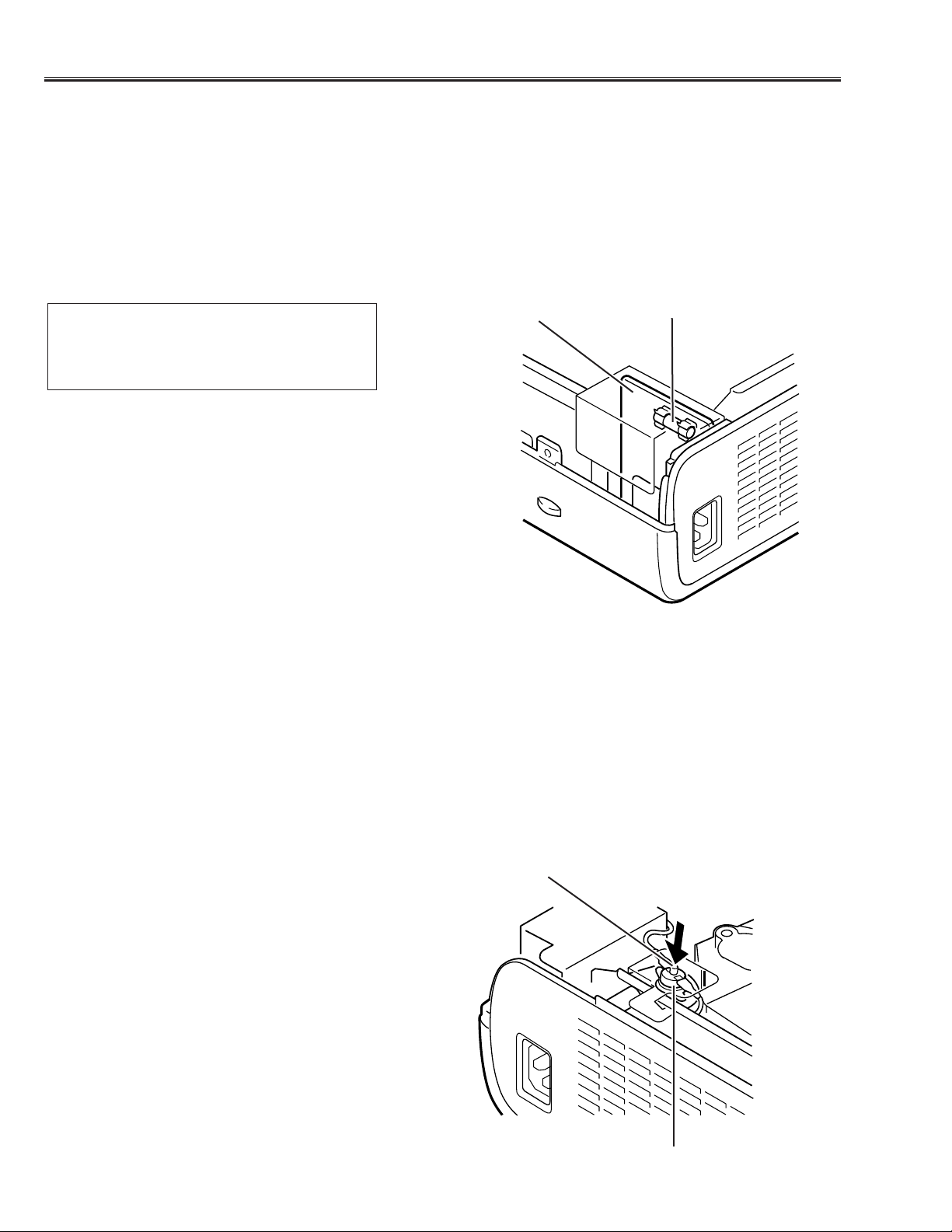
Fuse
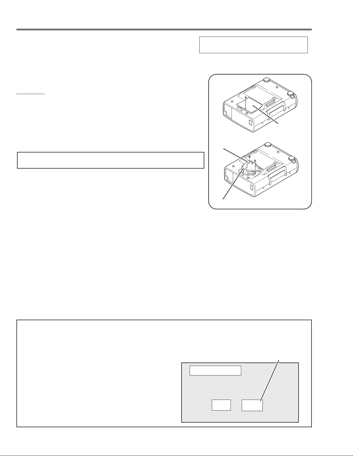
The fuse is located inside of the projector.When either the LAMP indicator or the READY indicator is not illuminated, fuse may be opened. Check the fuse as following steps.
It should be used the specified fuse as follows;
How to replace the fuse
1. Remove the cabinet top following to “Mechanical
Disassemblies”.
2. Remove the fuse from fuse holder.
To install the fuse, take reversed step in the above.
Fuse Part No.: 423 022 2102
TYPE T4.0AH 250V FUSE
LITTLE FUSE INC.TYPE 215004
Fuse
Line Filter Board
Thermal switch
There is the thermal switch (SW902) inside of the projector to prevent the internal temperature from rising abnormally. When the inter nal temperature reaches near 100˚C, turn off the AC main power supply automatically.
The thermal switch is not reset to normal automatically even if the internal temperature becomes normal. Reset the
thermal switch following procedure.
Check the resistance between terminals of thermal switch by using the tester. If it has high impedance, thermal
switch may be in operative.
How to reset the thermal switch
1. Remove the cabinet top following to “Mechanical
Disassemblies”.
2. Press the reset button on the thermal switch.
CAUTION:
Before press the reset button, disconnect the AC cord from
the projector.
Thermal switch (SW902)
Reset Button
Page 8
-7-
Circuit Protections
Warning temperature and power failure protection
The TEMP WARNING indicator flashes red and the projector will automatically turn off when the internal temperature of the projector exceeds the normal temperature or when stopping cooling fans or when the internal power supply lines are failed.
Check the following possible causes and wait until stopping the TEMP WARNING indicator flashing.
Possible causes
- Air filter is clogged with dust particles. Remove dust from the air filter by following instructions in the “Air filter care
and cleaning” below.
- Ventilation slots of the projector are blocked. In such an event, reposition the projector so that ventilation slots are
not obstructed.
- Check if projector is used at higher temperature place (Normal operating temperature is 5 to 35 ˚C)
If the TEMP WARNING indicator still continues to flash, there may be defects on cooling fans or power supply circuits. Please check fan operation and power supply lines referring to the “Power Supply Lines Chart”.
Air filter care and cleaning
The removable air filters prevents dust from accumulation on the surface of the projection lens and projection mirror.
Should be the air filter become clogged with dust particles, it will reduce the cooling fan’s effectiveness and may
result in internal heat build up and reduce the life of the projector.
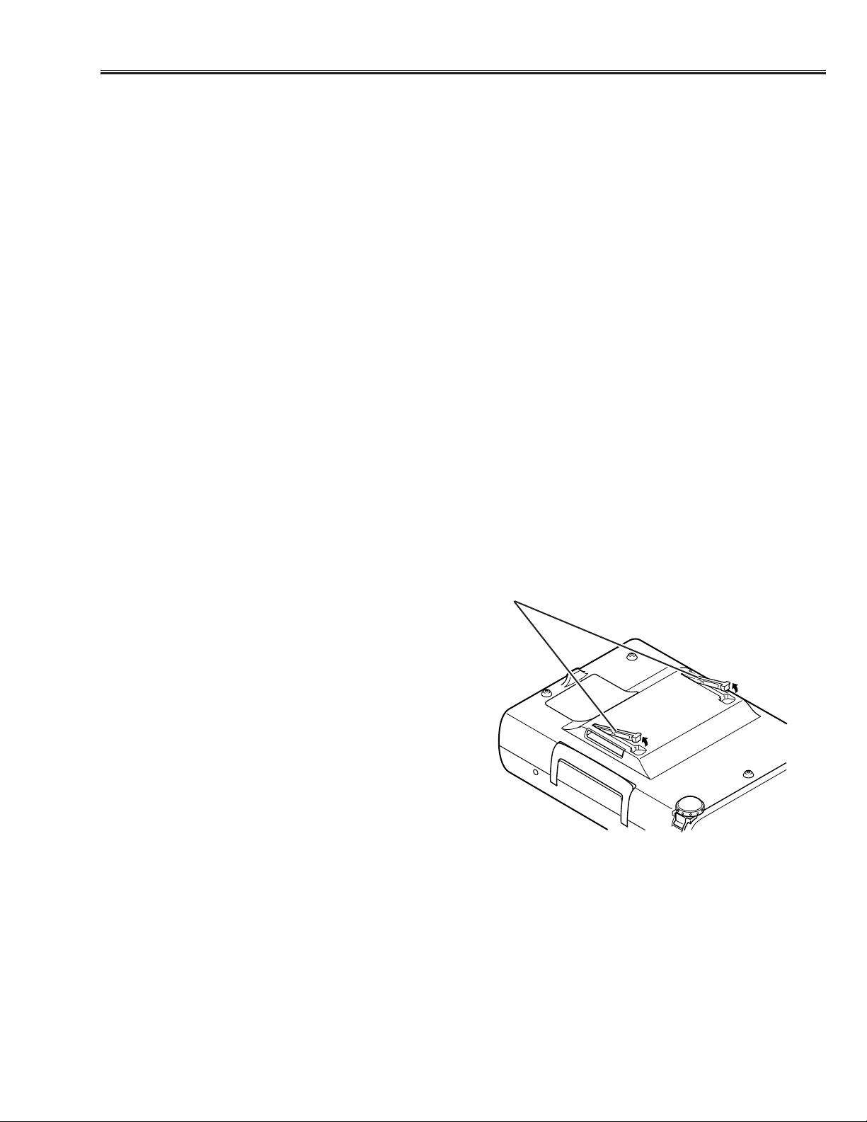
To clean up the air filters, follow the cleaning procedure
below:
1.Turn the power off, and disconnect the AC po w er cord
from the AC outlet.
2. Tur n the projector up side down and remove 2 air fil-
ters by pulling the latches of them upward.
3. Clean the air filters with brush or wash out the dust
and particles.
4. Replace the air filter.Make sure that the air filters are
fully inserted.
CAUTION:
Do not operate the projector with the air filter removed.
The dust is stuck on the LCD panel and the mirror, and
it may spoil the fine picture image.
Do not put the small parts into the air filter intake vents.
It result in the malfunction of the projector.The air filter
is small parts. Take care that children don’t eat or swallow it.
RECOMMENDATION
We recommend to avoid dusty, smoky place for operating the projector. Using in dusty place may cause the picture
of poor quality.
When using under the dusty or smoky conditions, dust may accumulate on the LCD panel and lens inside it, and
may resultantly be projected on the screen together with the picture.
When the above symptoms are noticed, please clean up the LCD panel and lens f ollowing to the “Cleaning Method”.
Air filters
Page 9
-8-
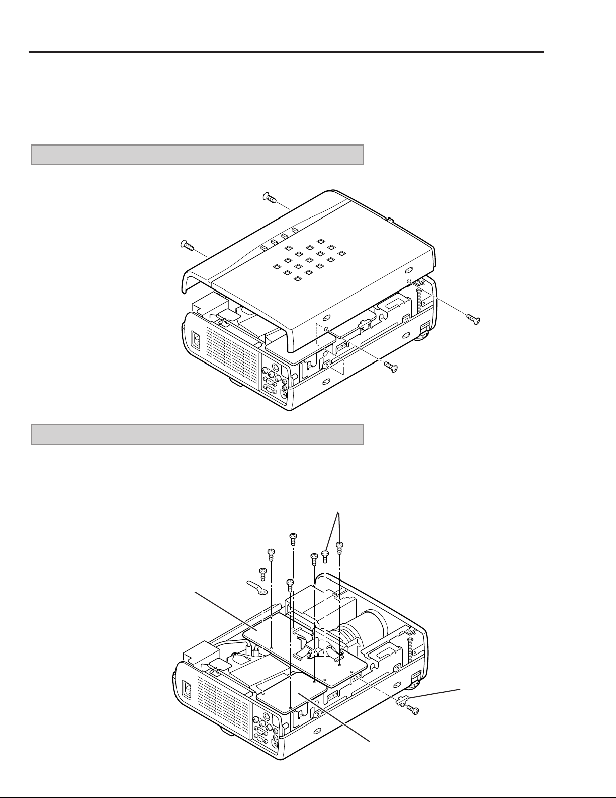
Remove 4 screws and pull cabinet top upward.
1. CABINET TOP REMOVAL
■ Mechanical Disassemblies
Mechanical disassemble should be made following procedures in numerical order.
Following steps show the basic procedures, therefore unnecessary step may be ignored.
Caution:
The parts and screws should be placed exactly the same position as the original otherwise it may cause loss of
performance and product safety.
Fig.1
1) Remove 3 screws (A) and take the AV SUB Board off upward.
2) Remove a screw (B) and a fixer, then disconnect the FPC cables.
3) Remove 4 screws (C) and pull the Main-B/C Boards off upward.
2. AV SUB, MAIN-B/C BOARD REMOVAL
Fig.2
C
C
C
A
A
A
B
Fixer
AV SUB Board
Main-B/C Board
Page 10
-9-
Mechanical Disassemblies
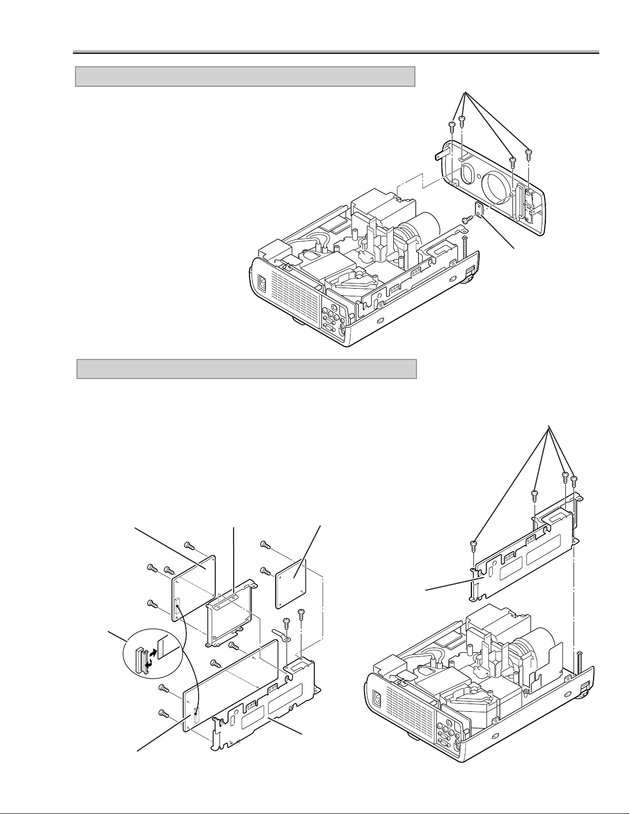
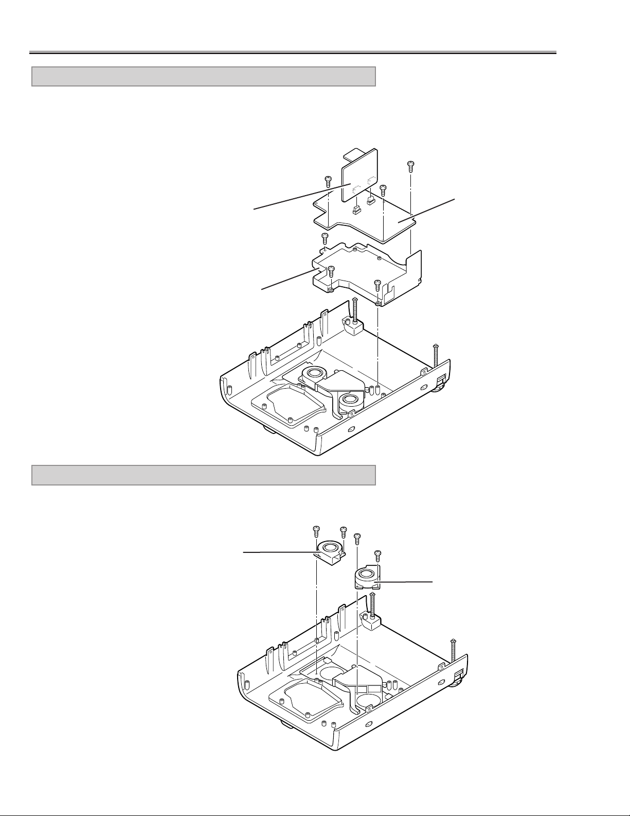
1) Remove 4 screws (A) and pull the Viewer and Main-A/D Board Ass’y
upward.
2) Remove 2 screws (B) and disconnect connector K1A, then take the
Viewer Board Ass’y off from the Main-A/D Board Ass’y.
3) Remove 4 screws (C) and take the Viewer Unit off from the Viewer
Mounting Holder.
4) Remove 2 screws (D) and remove the Main-D Board.
5) Remove 4 screws (E) and take the Main-A Board off from the Main-A
Board Holder.
4.VIEWER*, MAIN-A/D BOARD REMOVAL
1) Remove 4 screws (A) and remove the front cabinet forward.
2) Remove a screw (B) and remove the Viewer LED Board.
* Model without the PC Card slot does not provide the Vierwer LED Board.
3. FRONT CABINET, VIEWER LED BOARD* REMOVAL
Fig.3
A
A
Fig.4
Fig.5
D
D
B
B
E
E
E
E
C
C
C
C
Viewer Board *
Main-D Board
K1A
Main-A Board
Viewer, MainA/D Ass’y
Main-A Board
Holder
Viewer Board Holder
B
Viewer LED
Board *
* Model without the PC Card slot does not
provide the Vierwer Board.
Page 11
-10-
Mechanical Disassemblies
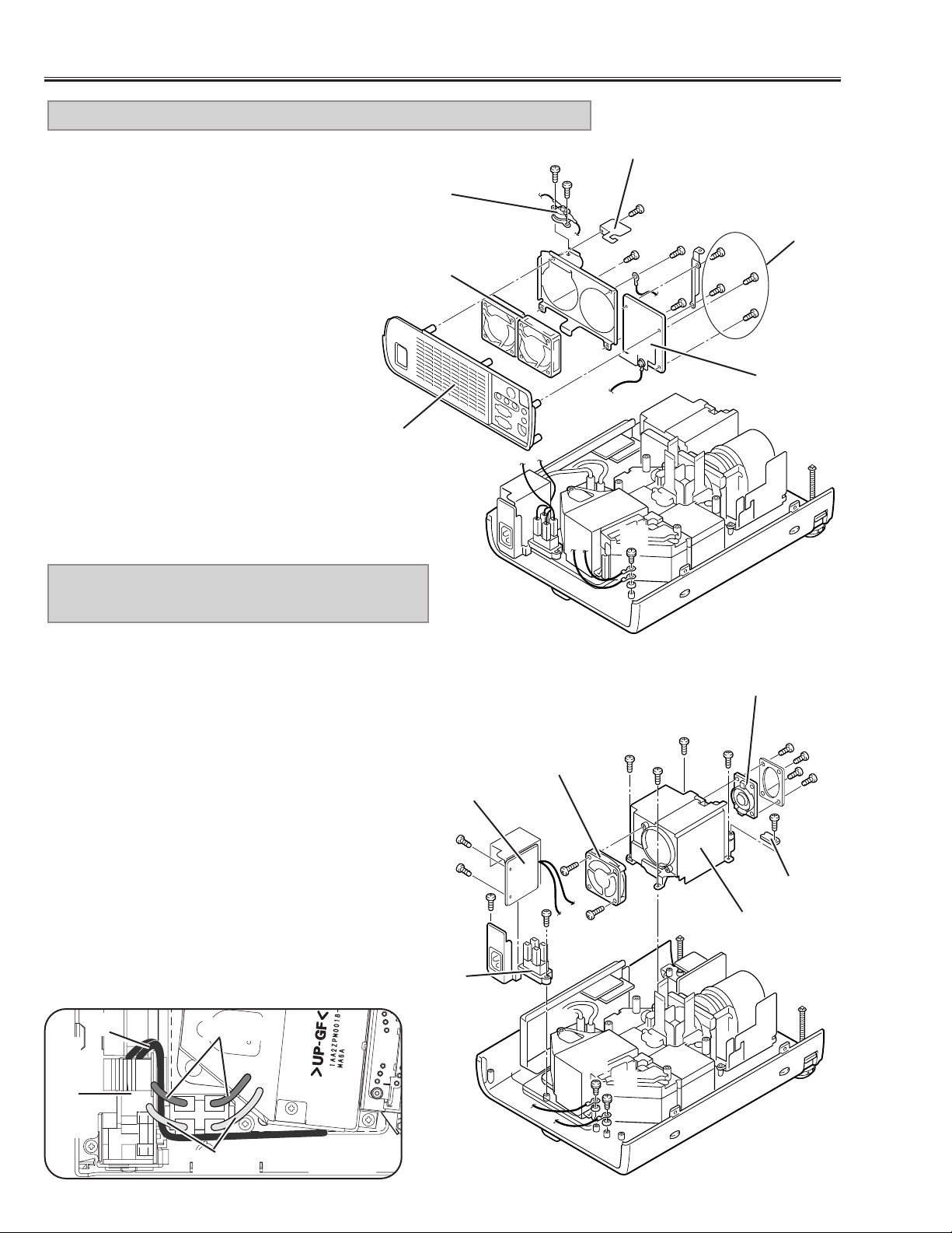
1) Pull the Rear Cabinet Ass’y upward.
2) Remove a screw (A) and take the
spacer off.
3) Remove 2 screws (B) and remove the
Thermal Switch (SW902).
4) Remove a screw (C) and remove the
grounding lead.
5) Remove 4 screws (D) and remove the
AV Board.
6) Remove 4 screws (E) and remove the
fans (FN904, FN905).
5. AV BOARD, REAR CABINET, FAN (FN904, FN905) REMOVAL
aab
b
c
c
d
d
Fig.6
C
D
B
B
E
E
A
E
Rear Cabinet
Fan
(FN904, FN905)
Thermal Switch
(SW902)
Spacer
AV Board
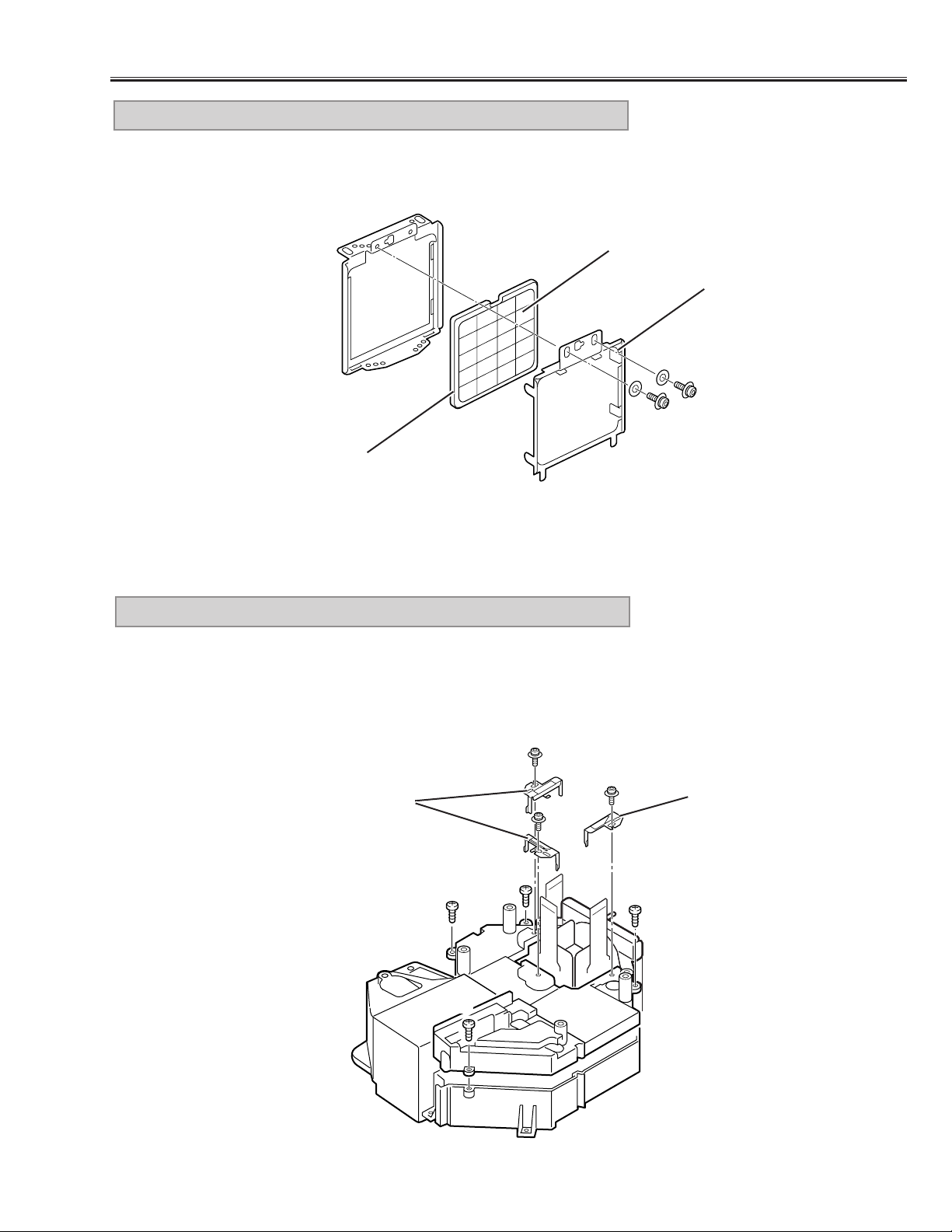
1) Remove 4 screws (A) and remove the Power Cover.
2) Remove 2 screws (B) and remove the Fan (FN901).
3) Remove 4 screws (C) and remove the Speaker.
4) Remove a screw (D) and remove R/C Board.
5) Remove 2 screws (E) and remove the grounding
leads.
6) Remove 2 screws (F) and pull the Filter & Interlock
Switch Ass’y.
7) Remove 2 screws (G) and then remove the Filter
Board and the Interlock Switch Ass’y.
Note:
* When fixing the grounding lead of the Filter Board,
disconnect the lamp socket (refer to Fig.8) first, and
fix the grounding lead then connect the lamp socket.
* Dress the grounding lead (e), (f) as show in Fig.7-2.
* Make sure of wires color as shown in Fig.7-2 when
connecting the sockets.
6. POWER COVER, FAN (FN901), FILTER
BOARD REMOVAL
C
A
A
A
C
A
E
R/C Board
Speaker
(SP901)
Power Cover
Fan(FN901)
D
B
B
F
E
Interlock Switch
(SW904)
F
G
G
Filter Board
Filter Board
Blue
Brown
Fig.7-1Fig.7-2
C
e, f
f
e
f
e
Page 12
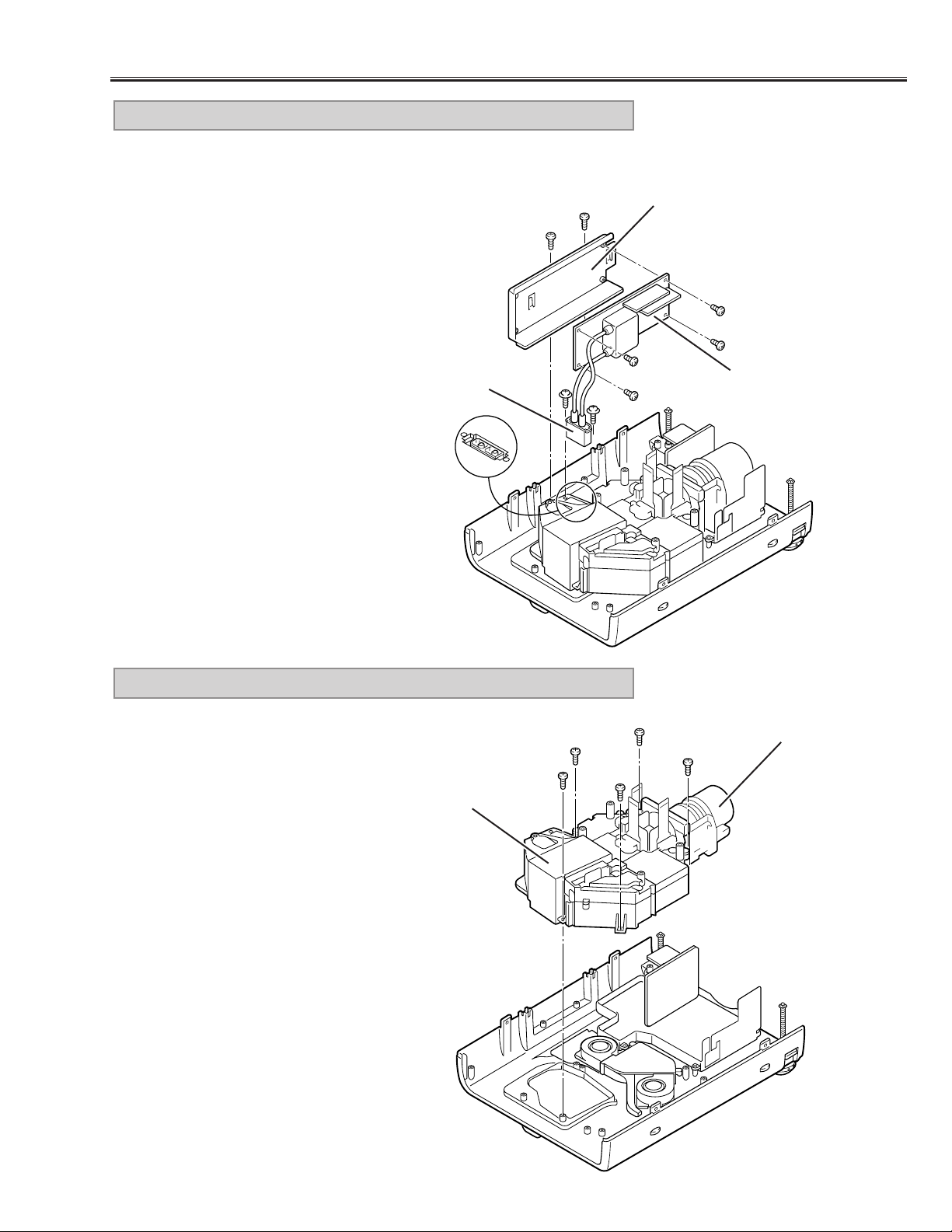
1) Remove 2 screws (A) and disconnect the lamp socket.
2) Remove 2 screws (B) and pull the Lamp Ballast Ass’y upward.
3) Remove 2 screws (C) and remove the Lamp Ballast Unit from
the Lamp Ballast Holder.
7. LAMP BALLAST UNIT REMOVAL
-11-
Mechanical Disassemblies
Fig.8
C
B
B
C
C
A
C
Lamp Socket
Lamp Ballast Holder
Lamp Ballast Unit
A
1) Remove 5 screws and pull the Optical Unit upward.
8. LENS, OPTICAL UNIT REMOVAL
Fig.9
Lens
Optical Unit
Page 13
-12-
Mechanical Disassemblies
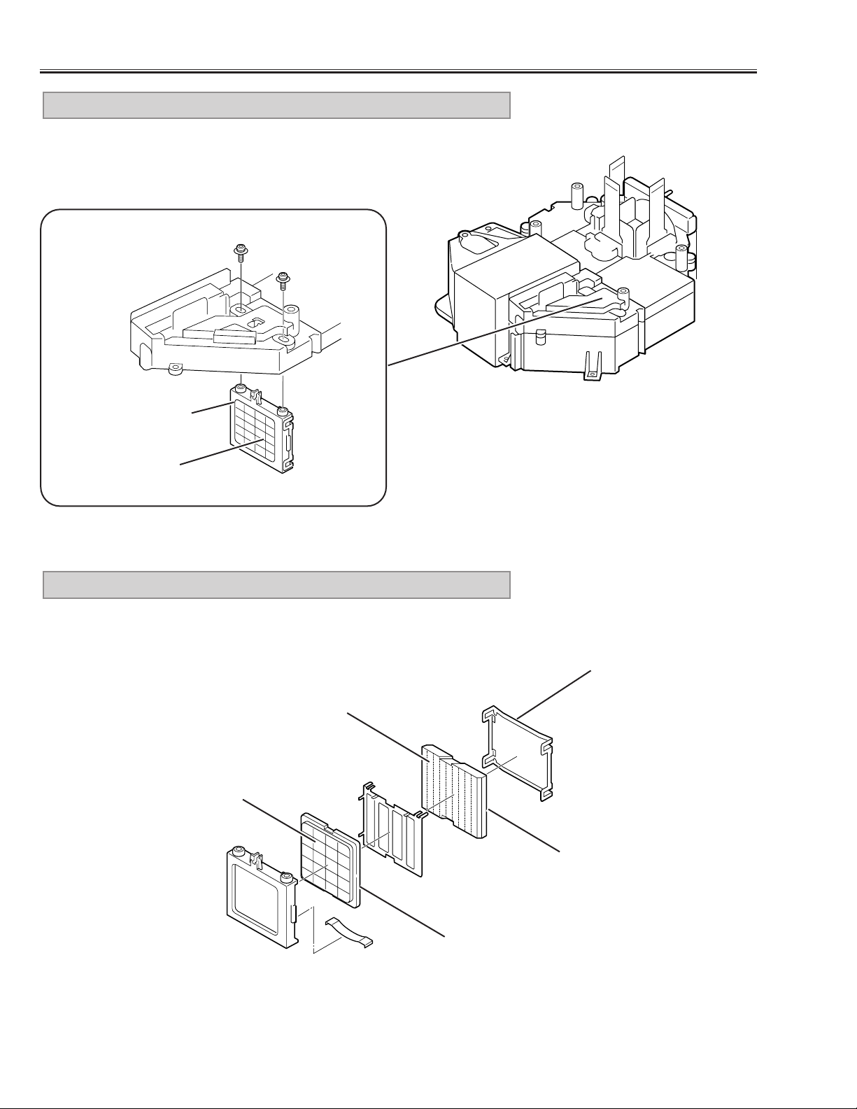
1) Remove screws (A) and pull the Power Board Ass’y upward.
2) Remove 3 screws (B) and take the Power Board off from the Power Board
Holder.
3) Remove the P.F.Board from the Power Board.
9. POWER, P.F. BOARD REMOVAL
Fig.10
Power Board
P.F. Board
1) Remove each 2 screws and take the Fans (FN902, FN903) off.
10. FAN (FN902, FN903) REMOVAL
Fig.11
Fan (FN902)
Fan (FN903)
P.F. Board Holder
A
A
A
B
B
B
Page 14
-13-
Mechanical Disassemblies
For servicing the A V, A V Sub, Main-A and Main-D Board, it is advisable to set
up the service position for the checking and testing easily following to below
steps
1) Remove the AV, AV Sub and Main-A/D Board following to steps 1~5 of
“Mechanical Disassemblies”.
* Should be remove the Main-A Board Holder and Viewer Holder.
2) Mount the AV, AV Sub, and Main-A/D Board to the Main-B Board.
* Not necessary to connect the Viewer Board.
Note:
In the mounting, make sure of the mounting direction of connectors.
11. SERVICE POSITION
Fig.12
Main-D Board
Main-B Board
AV Board
Main-A Board
AV Sub Board
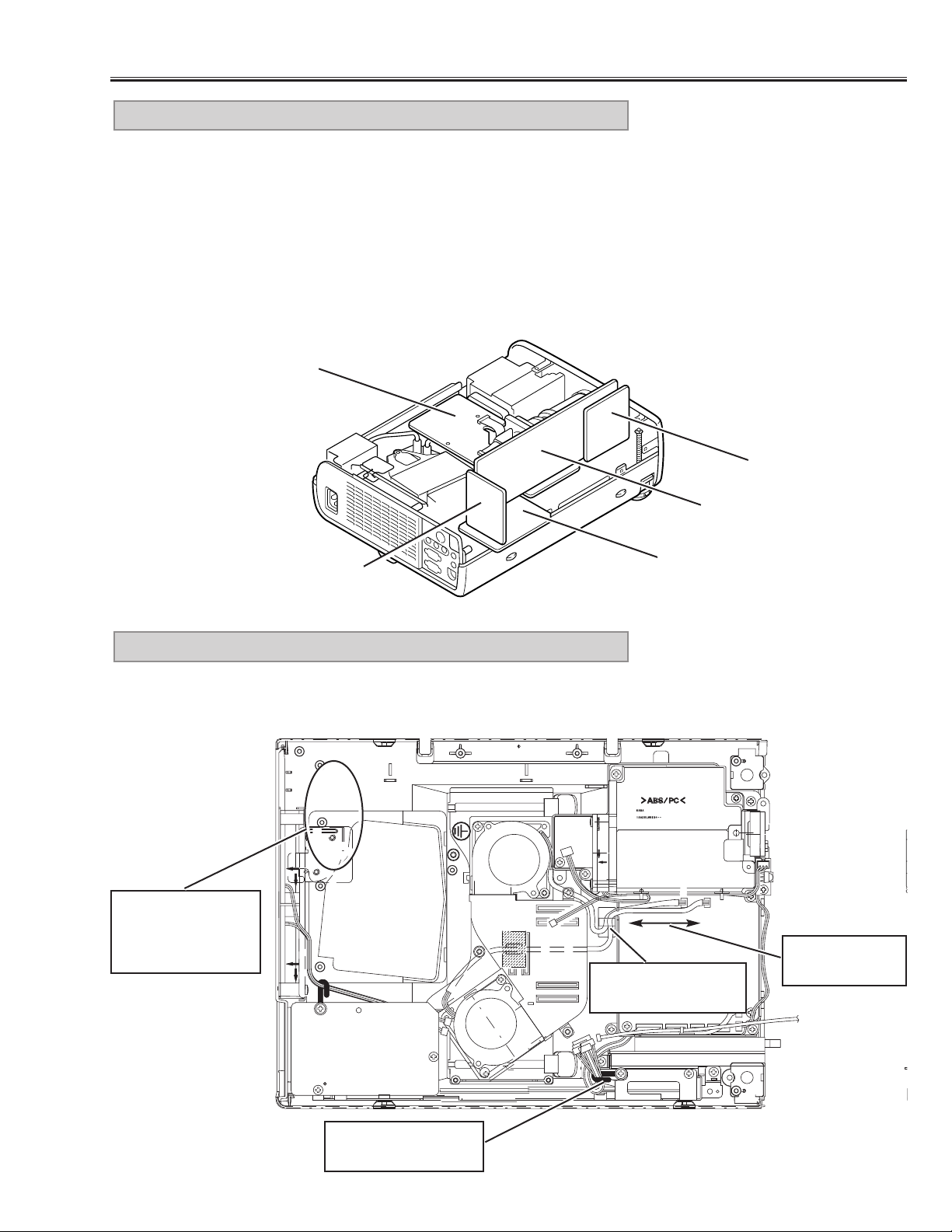
Make sure to dress the lead wires as follows when assembling the chassis
and cabinets
12. LEAD WIRE DRESSING
Fig.13
AV Sub Board
Do not loosen
these wires
Use a fixer for dressing these wires.
Fix wires firmly after
dressing.
Make sure that the
wires around here
are dressed not to
touch to the fans.
Page 15
-14-
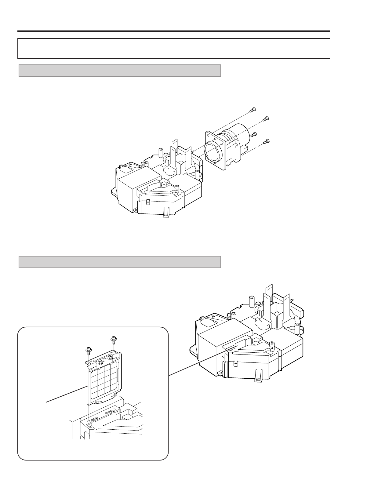
1) Remove the Optical Unit/Projection Lens following to the step 8 of
“Mechanical Disassemblies”.
2) Remove 4 screws and remove the Projection Lens.
1. PROJECTION LENS REMOVAL
Remove 2 screws (A) and pull the Integrator Lens-IN Ass’y upward.
2. INTEGRATOR LENS-IN ASS’Y REMOVAL
Fig.2
Fig.1
■ Optical Par ts Disassemblies
Remove the Cabinet Top , AV Sub, Main-B/C Board following to the “Mechanical Disassemblies”, before proceeding these disassemblies.
A
A
Integrator Lens-IN
Ass’y
Fig.3
Page 16
-15-
Remove 2 screws (A) and take the Integrator Lens-IN off from the lens
holder.
3. INTEGRATOR LENS-IN ASS’Y DISASSEMBLY
1) Remove each screw (A) and remove the Polarized Glass Holders.
2) Remove 4 screws (B) and take the Optical Unit Top off.
4. OPTICAL UNIT TOP REMOVAL
A
A
Lens Holder
Lens Surface
Integrator Lens-IN
Fig.4
Fig.5
Optical Pats Disassemblies
A
A
A
B
B
B
B
Polarized Glass Holder
Polarized Glass Holder
Page 17
-16-
Optical Parts Disassemblies
Remove 2 screws (A) and pull the Integrator Lens-OUT Ass’y downward.
5. INTEGRATOR LENS-OUT ASS’Y REMOVAL
Integrator Lens-OUT
Ass’y
Lens Surface
A
A
Fig.7
Fig.6
Remove the Lens Holder and disassembly the Integrator Lens-OUT Ass’y.
6. INTEGRATOR LENS-OUT ASS’Y DISASSEMBLY
Lens Holder
Prism Assy
(Beam Splitter)
Fig.8
Lens Surface
Integrator Lens-OUT
Surface attached the
phase sheet comes to
the lens holder.
Page 18
-17-
Optical Parts Disassemblies
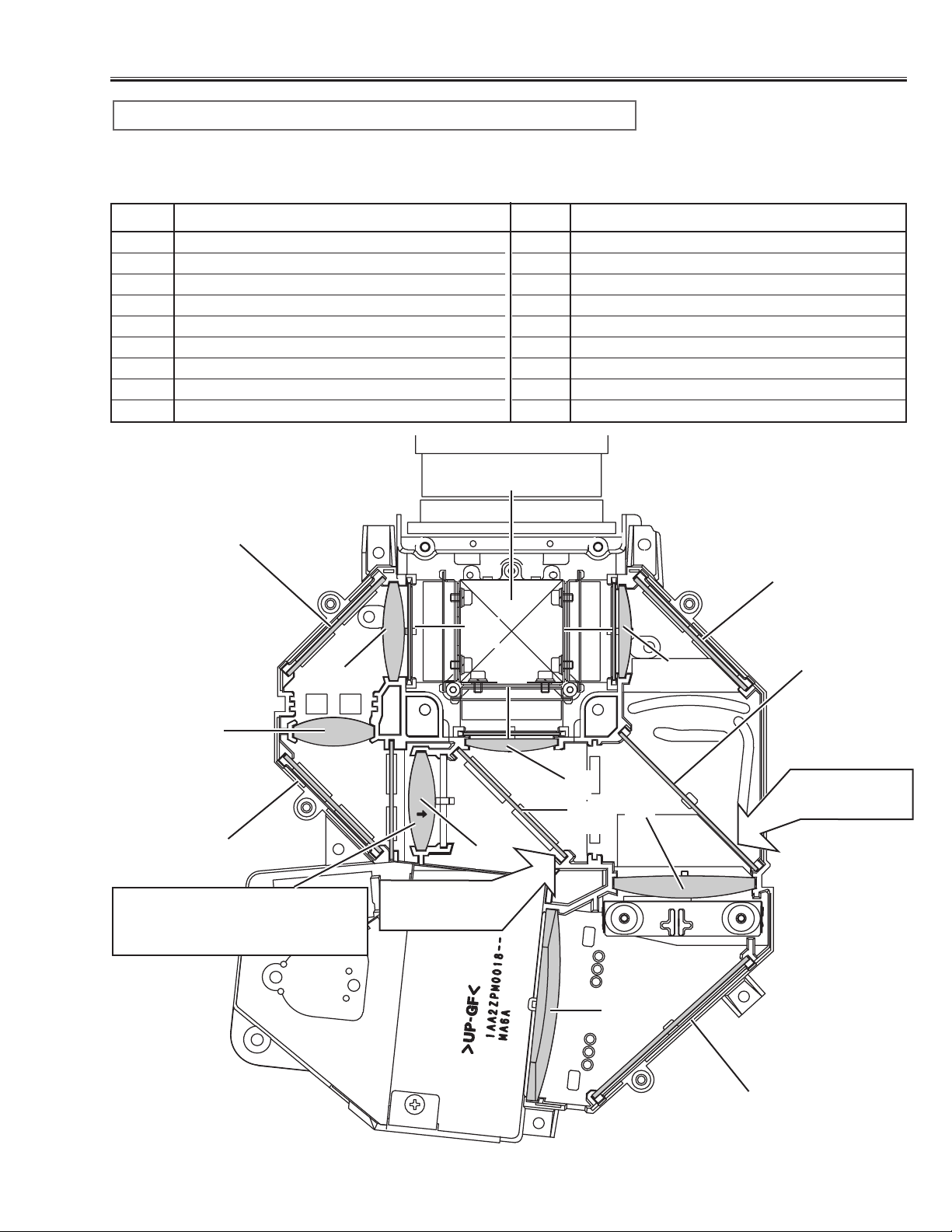
When the optical parts mounting or assembling, the parts must be mounted
in the specified location and direction. Please refer to the figure below and
“Mounting direction of optical parts” on next page.
1 Prism ass’y
2 Relay lens (IN)
3 Relay lens (OUT)
4 Condenser lens (IN)
5 Condenser lens (OUT)
6 Condenser lens
7 Condenser lens (B)
8 Mirror (W)
9 Mirror (R)
10 Mirror (B)
11 Optical Filter (UV cut)
12 Polarized glass (R-filter)
13 Polarized glass (IN/G)
14 Polarized glass (IN/B)
15 Dichroic mirror (R)
16 Dichroic mirror (G)
No. Part name No. Part name
1
3
2
4
5
6
7
13
14
8
12
Parts Name and Locations
11
16
15
Fig.9
10
9
10
6
Printed marker
comes this side
Printed marker
comes this side
Mount lens to be the same direction of the arrow marker on both of
the lens and optical base bottom.
Page 19

-18-
Optical Parts Disassemblies
The optical parts must be mounted in specified direction otherwise the picture image will not reproduce correctly.
● Mounting direction of Lens (Key No. 2, 3, 4, 5, 6, 7)
Lens (Key No. 2) is mounted as shown in Fig.9.
Lens (Key No. 3, 7) have no specified mounting direction.
Lens (Key No. 4, 5, 6,) are mounted as shown in Fig.9.
● Mounting direction of Mirrors (Key No. 8, 9, 10)
Mount the mirrors as the coating surface comes inside.
● Mounting direction of optical filter (Key No. 11)
The optical filter has no specified mounting direction.
● Mounting direction of polarized glasses (Key No. 2, 13, 14)
Mount each polarized glass as the face that the polarized film is attached comes the prism ass’y.
● Mounting direction of dichroic mirror (Key No. 15,16)
dichroic mirrors are mounted as shown in Fig.9.
Mounting direction of optical parts
Page 20
-19-
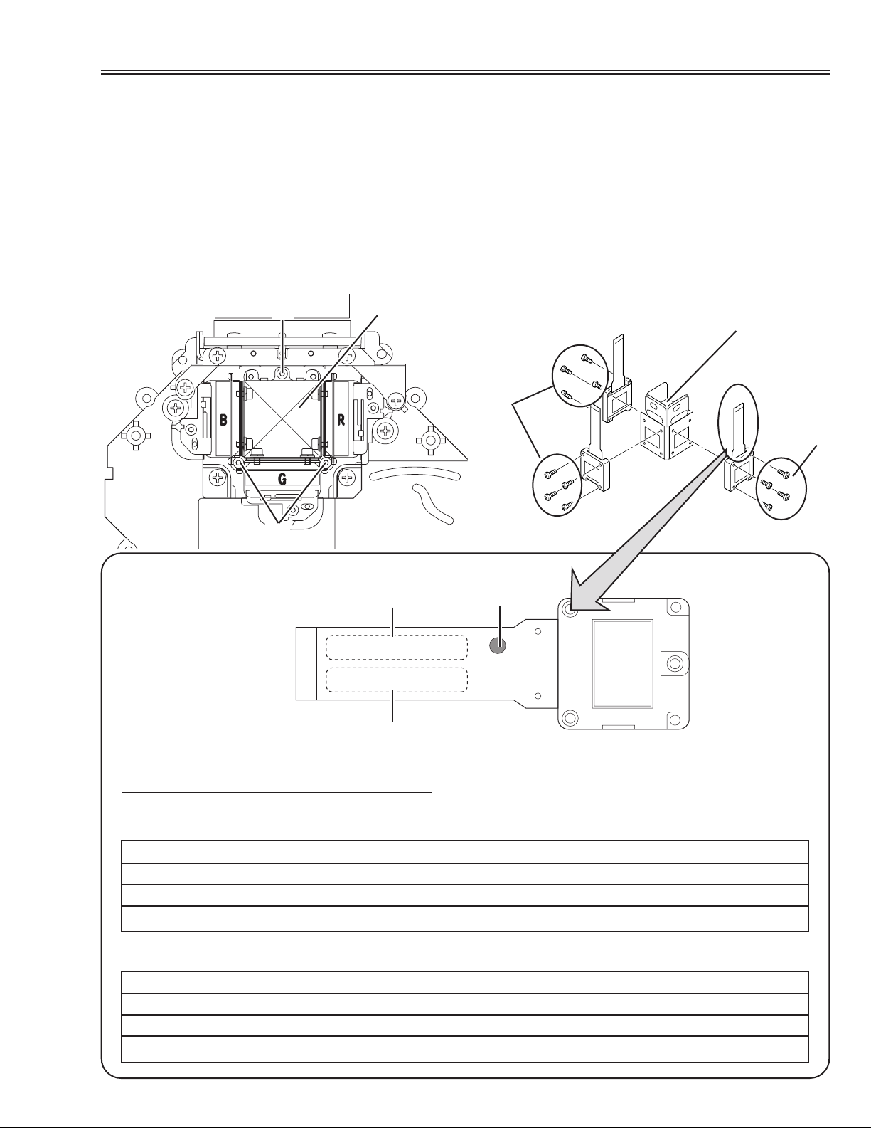
■ LCD Panel Replacement
● LCD PANEL REMOVAL
1. Remove the cabinet top following to “Mechanical Disassemblies”.
2. Remove 3 screws (A) by using 2.0mm hex driver, and then pull the prism/panel ass’y out from the optical base.
3. Remove 4 screws (B) to take off the LCD panel from the prism/panel ass’y.
When the LCD panel is replaced, it is required to re-adjust the white balance, convergence and common center
adjustments, and white uniformity adjustment if required. (Refer to the Optical and Electrical adjustments.)
Caution: Do not remove 3 panels (R,G,B) at the same time as it is necessary the standard panel for adjustment.
Do not fasten the screws with excessive force when mounting the LCD panel, otherwise focus adjustment
may be shifted.
COMBINATION-(1)
COMBINATION-(2)
SEAL PART NO. SERVICE PART NO.
R-LCD PANEL RED SEAL P09XG250 645 039 2955
G-LCD PANEL NO SEAL P09XG260 645 039 2948
B-LCD PANEL BLUE SEAL P09XG250 645 039 2962
SEAL PART NO. SERVICE PART NO.
R-LCD PANEL RED SEAL P09XG260 645 039 2986
G-LCD PANEL NO SEAL P09XG250 645 039 2979
B-LCD PANEL BLUE SEAL P09XG260 645 039 2993
A
A
B
B
Prism Ass’y
B-LCD Panel
G-LCD
Panel
R-LCD
Panel
SEAL
PART NO.
LOT NO.
Prism Ass’y
P09XG250
1-A-1234A9
When replacing the LCD panel, confirm the indication of the LCD panel, then replace the correct LCD panel.
Select either combination (1) or (2) when in combine the R, G and B LCD panel.
There is no combination to be used except them.
● NOTE ON LCD PANEL REPLACEMENT
Page 21
-20-
■ Lamp Replacement
WARNING:
- For continued safety, replace with a lamp assembly of the same type.
- Allow the projector to cool for at least 45 minutes before you open the lamp cover. The inside of the projector can
become very hot.
- Do not drop the lamp module or touch the glass bulb! The glass can shat-
ter and cause injury.
Procedure
1.Turn off the projector and disconnect the AC cord,.Allow the projector to
cool for at lease 45 minutes.
2. Remove a screw with a screwdriver and remove the lamp cover.
3. Remove 2 screws and pull out the lamp assembly by grasping the handle.
4. Replace the lamp assembly securely and tighten 2 screws.
5. Place the lamp cover and tighten a screw.
6. Connect the AC cord to the projector and turn on.
Note:
- Do not reset the LAMP REPLACEMENT MONITOR TIMER, except after
the lamp is replaced.
- The projector can not be turned-on with the lamp cover removed,
because when the lamp cover is removed, the interlock switch is also
released to switch off the mains power for safety.
7. Reset the lamp replacement monitor timer,see below explanation.
Service Parts No.: 610 280 6939
Description: Lamp Assy (POA-LMP21J)
How to reset the lamp replacement monitor timer
1.Turn the projector on. Press the MENU button on the
projector and the On-Screen menu will appear.Select
setting menu and select “Lamp age” on the setting
menu of menu bar.
2.“Lamp replace monitor Reset?” is displa y ed for confirmation.Select “Yes” to reset the lamp replace timer.
Please refer to the owners manual for further information.
Recommendation
Should the air filter become clogged with dust particles,
it will reduce the cooling fan’s effectiveness and may
result in internal heat build up and short lamp life. We
recommend cleaning the air filter after the projection
lamp is replaced.
Refer to “Air Filter Cleaning”.
How to check the lamp replace monitor
time
The LAMP REPLACEMENT indicator will illuminate
when the accumulated illumination time of the lamp
reaches 1000 hours.This is to indicate that lamp
replacement is necessary.
You can check the accumulated illumination time of
the lamp by following procedure.
1. Press and hold the pointer ▲ on the projector for
more than 20 seconds.
2.The projector enters to the service mode and the
accumulated time is displayed in the Data column
with hours unit. For example, when “123” is dis-
played, the accumulated illumination time of the
lamp is 123 hours.This will disappear in 5 seconds.
Lamp cover
Lamp Assembly
Handle
Video
Item Data
Service Mode
36
123
Accumulated illumination time of lamp
Page 22

-21-
[Before adjustment]
- Make sure each Red, Green and Blue LCD panel unit has been correctly installed.
- Input a grid pattern signal.
- Adjustment requires a 2.0mm hex wrench. Remove cabinet top following to the “Mechanical Disassemblies”.
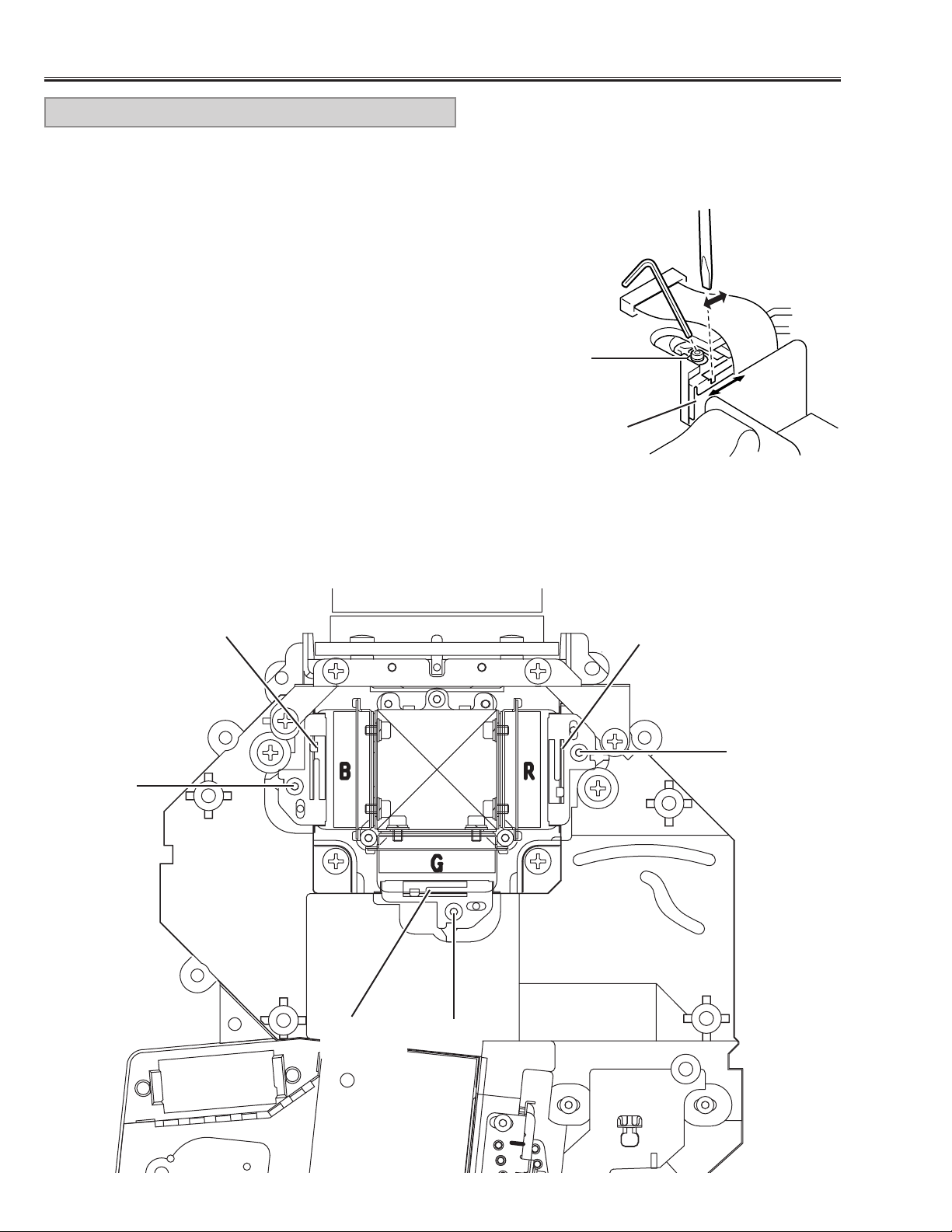
1.Insert paper etc. in Red or Blue panel to block the red
or blue light so that either green and red or green and
blue lights are projected. (For example, when adjust
Red panel convergence, project green and red lights,
and when adjust Blue panel, project green and blue
lights.)
2. Loosen 2 screws “D” (Fig.1) using the 2.0mm hex
wrench.
3.Turning the screw “A”, align so that the Red (or Blue)
horizontal lines are parallel to the Green horizontal
lines (Fig.1-a).
4. Turning screw “B”, align the Red (or Blue) vertical
lines onto the Green vertical lines (Fig.1-b).
5. Turning screw “C”, align the Red (or Blue) horizontal
lines onto the Green horizontal lines (Fig.1-b).
6. By repeating steps 3 to 5, align the Red (or Blue) grid
lines onto the green lines.
7.Tighten the 2 screws “D”to fix the Red (or Blue) panel
unit.
RED/BLUE PANEL CONVERGENCE
1. Adjustment screw “A” tur ns the image (Fig.1-a).
2. Adjustment screw “B” moves the image right and left
(Fig.1-b).
3. Adjustment screw ”C” moves the image up and down
(Fig.1-b).
[Image Movement and Screw Turning]
C: up/down
B: right/left
A: angle
D: Fixing
Fig.1-a
Red or Blue
Green
A
Fig.1-b
Red or Blue
Green
C
B
Red LCD panel
Blue LCD panel
For convergence adjustment, use Green as the reference standard. Align Red and Blue with Green by adjusting
the position and angle of the Red and Blue LCD panels. Screws “A”, “B”, “C” (Fig.1) are for convergence adjustment.
CONVERGENCE ADJUSTMENT
Fig.1
Fig.2
■ Optical Adjustments
Page 23
-22-
Optical Adjustments
[Before Adjustment]
- Adjustment requires a 2.0mm hex wrench and a slot screwdriver.
- Remove cabinet cover following to step1 of “Mechanical Disassemblies”.
- Input a 100% of black raster signal.
[R/G/B-CONTRAST ADJUSTMENT]
1. Insert paper etc. in front of the LCD panels to block unnecessary
lights.
When adjusting the R-Contrast, project red light only.
When adjusting the G-Contrast, project green light only.
When adjusting the B-Contrast, project blue light only.
2. Loosen a screw “A” (Fig.3/4) on the polarized glass mounting base
which you intend to adjust.
3. Turn the polarized glass mounting base by using a slot driver as
shown in Fig.3 to obtain the darkest brightness on the screen.
4.Tighten the screw “A”to fix the polarized glass mounting base.
Repeat steps 1 to 4 for remaining polarized glasses.
B-Polarized
glass
R-Polarized
glass
G-Polarized
glass
A
A
A
A
Fig.4
Fig.3
Polarized
glass
CONTRAST ADJUSTMENT
Page 24
-23-
Optical Adjustments
[Adjustment]
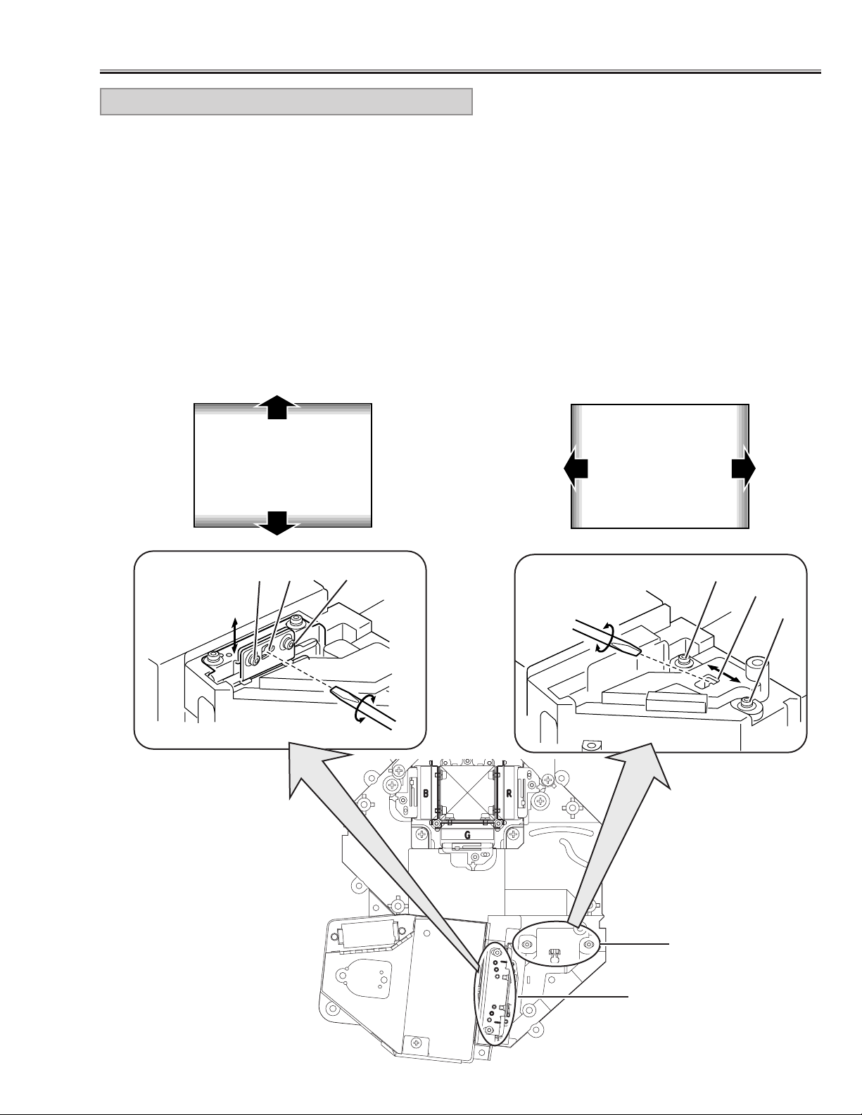
1.Turn on lamp by a state of without FPC cable of LCD
panels.
2. Inser t a light block sheet in front of the Blue panel to
block the blue light so that red and g reen light are projected.
3. Adjust the adjustment base of integrator lens-IN and
integrator lens-OUT to make color uniformity in yellow.
1) If the un-uniform color appears on the top or bottom of the screen as shown in Fig.5-a, loosen 2
screws “A” (Fig.5-b) with hex driver and insert a
slot screwdriver into slot “B” and turn it to make
color uniformity in yellow.
2) If the un-uniform color appears on the left or right
of the screen as shown in Fig.5-c, loosen 2 screws
“C” (Fig.5-d) with the hex driver and insert a slot
screwdriver into slot “D” and tur n it to make color
uniformity in yellow.
6. Tighten the 2 screws “A” or “C” to fix the integrator
lens-IN and OUT unit.
Slot B
Fig.5-b
Fig.5-a
Fig.5-c
INTEGRATOR LENS ADJUSTMENT
Yellow
A
A
Slot D
Fig.5-d
C
C
[Before Adjustment]
- Adjustment requires a 2.0mm hex driver and a slot screwdriver.
- Remove the cabinet top following to “Cabinet Disassemblies”.
- Disconnect AV sub board and connectors FPC cable of LCD panels on the main unit.
Yellow
Fig.5
Integrator Lens-IN
Integrator Lens-OUT
Page 25
-24-
■ Electrical Adjustments
● Service Adjustment Menu Operation
IC302 on the main board-A stores the data for the service adjustments, and should not be replaced except
for the case of defective device.
If replaced, it should be performed the re-adjustments
following to the “Electrical Adjustments”.
The lamp replacement monitor timer is stored in the
IC302, and it can be confirmed at the item no. 36 of
service mode.
Please note that the lamp replacement monitor timer is
reset when the memory IC (IC302) is replaced.
(Lamp replacement monitor time can not be set to the
previous value.)
● Caution to memory IC replacement
When IC302 is replaced with new one, the CPU writes
down the default data of the service adjustments to the
replaced IC, refer to the service adjustment table. As
these data are not the same data as factory shipped
data, it should be required to perform the re-adjustments following to the “Electrical Adjustments”.
Please note that the lamp replacement monitor timer is
reset.
● Caution of Main Board replacement (in the case
IC302 is not defective)
When the main board-A is replaced, IC302 should be
replaced with the one on previous main board. After
replacement, it should be required to perform the readjustments following to the “Electrical Adjustments”.
In this case, the lamp replacement monitor timer and
the white uniformity compensation data can be kept the
value as before.
● Memory IC Replacement
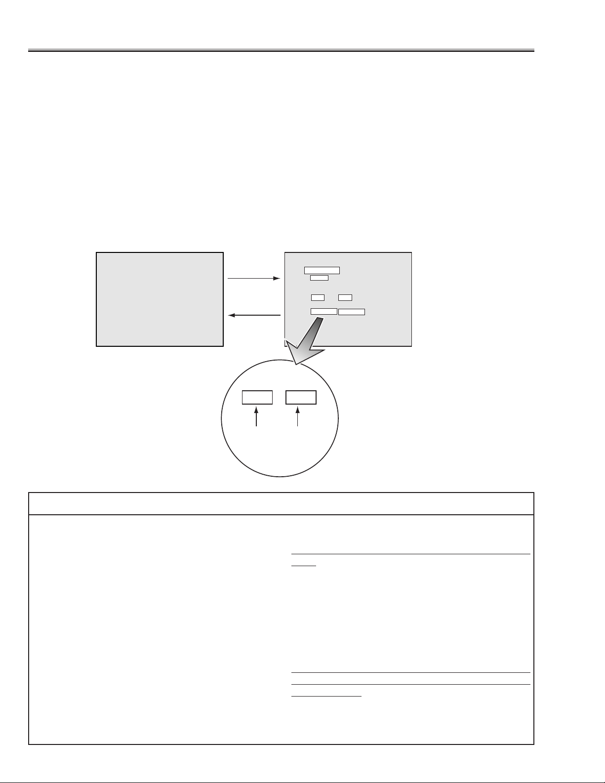
To enter the ser vice mode
To enter the “Service Mode”, press and hold the MENU and NORMAL button on the projector for more than 3 seconds.The ser vice mode display appears on the screen as follows.
To adjust ser vice data
Select the adjustment item no.by pressing the pointer ▲ or ▼ button, and change the data value by pressing the
VOLUME + or VOLUME - button. Refer to the “Ser vice Adjustment Data Table” for further descroption of adjustment item no.and data value.
To exit the service mode
To exit the service mode, press any of the POWER ON-OFF, MENU, MODE, FOCUS or ZOOM buttons on the pro-
jector or remote control unit.
Normal mode Service mode
Service Mode
Video
Item
Data
10
15
Version : 1.0
Item Data
10 15
Adjustment
Item No.
Adjustment
Data Value
Page 26

-25-
After replacing the Power Board, PF.C. Board, readjust
the Output voltage adjustment as follows.
1. Connect a digital voltmeter to pins 1 (+) and 3 (-) of
K6C.
2. Adjust the voltage by using VR01 as following.
AC Input Reading
230V 370V ±2V
120V 320V ±2V
Caution:
Be sure to connect the lamp when taking this adjustment.
OUTPUT VOLTAGE ADJUSTMENT
● Circuit Adjustments
CAUTION:The each circuit has been made by the fine adjustment at factory. Do not attempt to adjust the follow-
ing adjustments except requiring the readjustments in servicing otherwise it may cause loss of performance and product safety.
[Adjustment Condition]
● Input signal
Video signal ..................1.0Vp-p/75Ω terminated, 16 steps gray scale or color bar pattern
Computer signal............0.7Vp-p/75Ω terminated, 16 steps gray scale pattern
MCI signal * ..................16 steps gray scale pattern from PC Card
● Picture control mode ---------- “NORMAL” mode unless otherwise noted.
Note:
* Please refer to “Service Adjustment Menu Operation” for entering to the service mode and adjusting the service
data.
* It is not available the MCI mode for model which does not provide the PC Card slot.
Electrical Adjustments
Presetting
1. Receive the 16-step grey scale video signal.
2. Set to VIDEO mode.
[R-PEDESTAL ADJUSTMENT]
3. Connect an oscilloscope to test point “TP221R” (+)
and chassis ground (-).
4. Enter to the service mode, select item no. “27” and
change data value to adjust the pedestal level and
black level to be same level.
[G-PEDESTAL ADJUSTMENT]
5. Connect an oscilloscope to test point “TP221G” (+)
and chassis ground (-).
6. Select item no.“28” and change data value to adjust
the pedestal level and black level to be same level.
[B-PEDESTAL ADJUSTMENT]
7. Connect an oscilloscope to test point “TP221B” (+)
and chassis ground (-).
8. Select item no.“29” and change data value to adjust
the pedestal level and black level to be same level.
PEDESTAL ADJUSTMENT
Pedestal level = Black level
Page 27
-26-
Electrical Adjustments
[CG-VIDEO GAIN ADJUSTMENT]
1. Receive the 16-step grey scale computer signal.
2. Set to COMPUTER mode.
3. Connect an oscilloscope to test point “TP2221G” (+)
and chassis ground (-).
4. Enter to the service mode, select item no. “48” and
change data value to adjust “a”to be 1.15 ±0.01Vp-p.
[MCI-VIDEO GAIN ADJUSTMENT] *
5. Receive the 16-step grey scale MCI signal.
6. Set to MCI mode.
7. Connect an oscilloscope to test point “TP2221G” (+)
and chassis ground (-).
8. Enter to the service mode, select item no. “48” and
change data value to adjust “a”to be 1.15 ±0.01Vp-p.
VIDEO GAIN ADJUSTMENT-[CG/MCI]
1. Receive the 16-step gray scale video signal.
2. Set to COMPUTER mode.
[R-OFFSET ADJUSTMENT]
3. Connect an oscilloscope to test point “TP2211R” (+)
and chassis ground (-).
4. Enter to the service mode, select item no. “45” and
change data value to adjust the pedestal level and
black level to be same level.
[G-OFFSET ADJUSTMENT]
5. Connect an oscilloscope to test point “TP2221G” (+)
and chassis ground (-).
6. Select item no.“46” and change data value to adjust
the pedestal level and black level to be same level.
[B-OFFSET ADJUSTMENT]
7. Connect an oscilloscope to test point “TP2231B” (+)
and chassis ground (-).
8. Select item no.“47” and change data value to adjust
the pedestal level and black level to be same level.
OFFSET ADJUSTMENT-[CG]
(a)
Pedestal level = Black level
Pedestal level = Black level
Page 28
-27-
Electrical Adjustments
Presetting
1. Receive the 16-step grey scale video signal.
2. Set to VIDEO mode.
[R-VIDEO GAIN ADJUSTMENT]
3. Connect an oscilloscope to test point “TP2211R” (+)
and chassis ground (-).
4. Enter to the service mode, select item no. “49” and
change data value to adjust “a”to be 1.15 ±0.02Vp-p.
[G-VIDEO GAIN ADJUSTMENT]
5. Connect an oscilloscope to test point “TP2221G” (+)
and chassis ground (-).
6. Enter to the service mode, select item no. “50” and
change data value to adjust “a”to be 1.15 ±0.02Vp-p.
[B-VIDEO GAIN ADJUSTMENT]
7. Connect an oscilloscope to test point “TP2231B” (+)
and chassis ground (-).
8. Enter to the service mode, select item no. “51” and
change data value to adjust “a”to be 1.15 ±0.02Vp-p.
VIDEO-GAIN ADJUSTMENT-[AV]
Presetting
1. Receive the 16-step grey scale computer signal.
2. Set to COMPUTER mode.
[R-VIDEO CENTER ADJUSTMENT]
3. Connect a digital voltmeter to test point “TP511” (+)
and chassis ground (-).
4. Adjust voltage to be 7.30 ±0.05V by using VR501.
[G-VIDEO CENTER ADJUSTMENT]
5. Connect a digital voltmeter to test point “TP512” (+)
and chassis ground (-).
6. Adjust voltage to be 7.30 ±0.05V by using VR531.
[B-VIDEO CENTER ADJUSTMENT]
7. Connect a digital voltmeter to test point “TP513” (+)
and chassis ground (-).
8. Adjust voltage to be 7.30 ±0.05V by using VR561.
VIDEO CENTER ADJUSTMENT
1. Receive the 16-step grey scale computer signal.
2. Set to COMPUTER mode.
3. Connect an oscilloscope to test point “TP2571” (+)
and chassis ground (-).
4. Adjust “a” to be 5.5 ±0.1V by using VR3351.
NRS ADJUSTMENT
[GAMMA OFF ADJUSTMENT-CG]
1. Receive the 16-step gray scale computer signal.
2. Set to COMPUTER mode.
3. Connect an oscilloscope to test point “TP512” (+) and
chassis ground (-).
4. Enter to the service mode, select item no. “0” and
change data value to adjust “a”to be 1.70 ±0.01Vp-p.
[GAMMA OFF ADJUSTMENT-AV]
5. Receive the 16-step gray scale video signal.
6. Set to VIDEO mode.
7. Connect an oscilloscope to test point “TP512” (+) and
chassis ground (-).
8. Enter to the service mode, select item no. “0” and
change data value to adjust “a”to be 1.70 ±0.01Vp-p.
GAMMA OFF VIDEO ADJUSTMENT
(a)
(a)
(a)
Pedestal level = Black level
Page 29
-28-
1. Receive the 16-step gray scale computer signal.
2. Set to COMPUTER mode.
3. Connect an oscilloscope to test point “TP512” (+) and
chassis ground (-).
4. Enter to the service mode, select item no. “3” and
change data value to adjust “a”to be maximum.
S/H CLOCK ADJUSTMENT
Electrical Adjustments
Presetting
1. Input the 16-step gray scale video signal, MCI signal
and computer signal.
[CG/MCI/AV-VIDEO ADJUSTMENT] *
2. Connect an oscilloscope to test point “TP512” (+) and
chassis ground (-).
3. Enter to the service mode, select item no. “15” and
change data value to adjust “b”to be 1.0Vp-p at each
VIDEO, MCI and COMPUTER mode.
4. Select COMPUTER and MCI mode, select item no.
“12” and change data value to adjust “a” to be 4.05
±0.01Vp-p.
5. Select VIDEO mode, select item no.“12” and change
data value to adjust “a”to be 4.05 ±0.01Vp-p.
[R-VIDEO ADJUSTMENT]
6. Connect an oscilloscope to test point “TP511” (+) and
chassis ground (-).
7. Enter to the service mode and select COMPUTER
mode.
8. Select item no. “13” and change data value to adjust
“a” to be 4.05 ±0.01Vp-p.
9. Select VIDEO mode and item no. “13” and change
data value to adjust “a”to be 4.05 ±0.01Vp-p.
[B-VIDEO ADJUSTMENT]
10. Connect an oscilloscope to test point “TP513” (+)
and chassis ground (-).
11.Enter to the service mode and select COMPUTER
mode.
12. Select item no.“14” and change data value to adjust
“a” to be 4.05 ±0.01Vp-p.
13. Select VIDEO mode and item no. “14” and change
data value to adjust “a”to be 4.05 ±0.01Vp-p.
CG/MCI/A V VIDEO ADJUSTMENT -1
[CG-VIDEO ADJUSTMENT-2]
1. Receive the 16-step grey scale computer signal.
2. Set to COMPUTER mode.
3. Connect an oscilloscope to test point “TP512” (+) and
chassis ground (-).
4. Enter to the service mode, select item no. “15” and
change data value to adjust “b”to be 2.10 ±0.01Vp-p.
[MCI-VIDEO ADJUSTMENT-2] *
5. Receive the 16-step grey scale MCI signal.
6. Set to MCI mode.
7. Connect an oscilloscope to test point “TP512” (+) and
chassis ground (-).
8. Enter to the service mode, select item no. “15” and
change data value to adjust “b”to be 2.10 ±0.01Vp-p.
[AV-VIDEO ADJUSTMENT-2]
9. Receive the 16-step grey scale video signal.
10. Set to VIDEO mode.
11. Connect an oscilloscope to test point “TP512” (+)
and chassis ground (-).
12. Enter to the ser vice mode, select item no. “15” and
change data value to adjust “b”to be 2.15 ±0.01Vp-p.
CG/MCI/A V VIDEO ADJUSTMENT -2
white level
(b)
white level
(a)
black level
white level
(b)
white level
(a)
black level
(a)
Page 30

-29-
Electrical Adjustments
[CG WHITE BALANCE ADJUSTMENT]
1. Receive the 16-step grey scale computer signal.
2. Set to COMPUTER mode.
3. Enter to the ser vice mode, select item no. “16” (Red)
or “17”(Blue), and change data values respectively to
make a proper white balance.
[MCI WHITE BALANCE ADJUSTMENT] *
4. Receive the 16-step grey scale MCI signal.
5. Set to MCI mode.
6. Select item no. “16” (Red) or “17” (Blue), and change
data values respectively to make a proper white balance.
[A V WHITE BALANCE ADJUSTMENT]
7. Receive the 16-step grey scale video signal.
8. Set to VIDEO mode.
9. Select item no. “16” (Red) or “17” (Blue), and change
data values respectively to make a proper white balance.
Confirm that the same white balance is obtained in
video, MCI and computer mode.
WHITE BALANCE ADJUSTMENT
1. Receive the 16-step gray scale computer signal.
2. Set to COMPUTER mode.
[R-COMMON CENTER ADJUSTMENT]
3. Cover the G and B panel to block the light transit.
4. Adjust VR2502 to obtain the minimum flicker on the
picture.
[G-COMMON CENTER ADJUSTMENT]
5. Cover the R and B panel to block the light transit.
6. Adjust VR2503 to obtain the minimum flicker on the
picture.
[B-COMMON CENTER ADJUSTMENT]
7. Cover the G and R panel to block the light transit.
8. Adjust VR2504 to obtain the minimum flicker on the
picture.
COMMON CENTER ADJUSTMENT
[AV BLACK BALANCE ADJUSTMENT]
1. Receive the 16-step grey scale video signal.
2. Set to VIDEO mode.
3.Enter to the service mode, select item no.“9” (Red) or
“10” (Blue), and change data values respectively to
make a proper white balance at darker part of the
screen.
BLACK BALANCE ADJUSTMENT
Page 31

-30-
Electrical Adjustments
White uniformity compensation adjustment system of this model divided the screen into 13 in vertical direction and
16 in horizontal direction and specified the area by using its co-ordinate, and then adjust the RGB white balance
on the specified area, refer to the figure below.
Please note that the selected area and dividing lines are not indicated on the screen. Roughly select the area you
wish to adjust with vertical and horizontal address number as shown figure below.
[Before adjustment]
- Set to normal display mode.
- Confirm the white uniformity compensation mode on.
Enter to the service mode , select item no.“83” and confir m that the data value is “186” (mode On). If the data
value is “58”(mode OFF), change value to “186” by pressing the VOLUME ▲ or VOLUME ▼ button.
- Initialize the all of compensation data. (This is required when the LCD panel is replaced more than 2 panels.)
1) Enter to the service mode, select item no. ”82” and increase the data value from “0” to “10”. When the value
reaches “10”, the data value is automatically return to “0”and the initializing has been completed.The all of
compensation data for RGB are to be “32”.
- Mode :Video or Computer mode
- Input Signal : White raster signal
- Picture control : Nor mal level
[How to adjust white uniformity]
[1] Enter to the service mode.
[2] Chose the area you wish to adjust. For example, choosing 3rd area from the top and 10th area from the left.
Select Item No.“77” (Vertical area no. selection mode) and select Data No. “2” , and select Item No. “78”
(Horizontal area no.selection mode) and select Data No.”9” .The area no. star ts from “0”.
[3] Adjust white balance in selected area.
Select Item No.”79” (Red), “80”(Green) or “81” (Blue), and change data value to adjust white balance.
[4] Repeat steps 2 to 3 until obtaining better white uniformity.
[5] Exit from the service mode.
WHITE UNIFORMITY ADJUSTMENT
This adjustment should be carried out when existing unbalanced white uniformity on the screen or after replacing
the LCD panels. (When replacing the main board-A, the memory IC, IC302 on the main board-A should be
replaced with the one on previous board, so that the white uniformity adjustment may not be required because
the data of white uniformity adjustment are stored in this memory IC, IC302.)
Item Initial Value Range Description
77 0 0 ~ 12 Vertical area no. selection
78 0 0 ~ 15 Horizontal area no. selection
79 32 0 ~ 63 Red white balance adjustment
80 32 0 ~ 62 Green white balance adjustment
81 32 0 ~ 62 Blue white balance adjustment
82 0 0 ~ 10 Reset of white uniformity comp. data
83 186 58 or 186 White uniformity comp. On/Off
0123456789 10 11 12 13 14 15
0
1
2
3
4
5
6
7
8
9
10
11
12
Service Mode
Video
Item Data
77 2
Item : <77> Data : <2>
Item : <78> Data : <9>
Page 32

COMPUTER MCI VIDEO
0 RGB AMP (Gamma OFF) ✻ 20 20 * ~ * ✻ GAMMA OFF G-VIDEO ADJUSTMENT
1 RGB AMP(Gamma ON) 20 20 * ~ * This operates together with Gamma R/G/B Amps, so when one of the R, G, B
value reaches maximum or minimum value, the up/down operation stops.
2 S&H Display Position of S/H Test Pattern 3 0 ~ 12 Display the Test Pattern
3 GAMMA DLYCNT ✻ 15 0 ~ 63 ✻ S/H CLOCK ADJUSTMENT
4 GAMMAG BIAS 13 0 ~ 63
5 Not Used
6 GAMMAR BIAS 13 0 ~ 63
7 Not Used
8 GAMMAB BIAS 13 0 ~ 63
9 GAMMAR-B1P ✻ 27 27 0 ~ 63 ✻ BLACK BALANCE ADJUSTMENT[RED]
10 GAMMAB-B1P ✻ 27 27 0 ~ 63 ✻ BLACK BALANCE ADJUSTMENT[BLUE]
11 GAMMAG-B1P 27 27 0 ~ 63
12 DAC CLAMP LEVEL(SUB BRIGHT) ✻ 48 48 48 0 ~ 63 ✻ CG/MCI/AV-VIDEO ADJUSTMENT-1
13 Gamma Amp R ✻ 20 20 0 ~ 63 ✻ R-VIDEO ADJUSTMENT
14 Gamma Amp B ✻ 20 20 0 ~ 63 ✻ B-VIDEO ADJUSTMENT
15 DAC RGB BIAS ✻ 40 40 40 0 ~ 127 ✻ CG/MCI/AV-VIDEO ADJUSTMENT-2
16 DAC R BIAS ✻ 40 45 48 0 ~ 127 ✻ CG-WHITE BALANCE ADJUSTMENT[RED]
17 DAC B BIAS ✻ 40 45 48 0 ~ 127 ✻ CG-WHITE BALANCE ADJUSTMENT[[BLUE]
18 DAC GAIN(SUB-CONT) 55 55 58 0 ~ 63
19 S&H B-CK 15
20 S&H G-CK 15
21 S&H R-CK 15
22 S&H B-SH 7
23 S&H G-SH 7
24 S&H R-SH 7
25 S & H HCK PHASE ADJUSTMENT 5
26 cxa2076 AV Sub-Color Adjustment 6
27 cxa2076 AV RGB Pedestal ADJUSTMENT ✻ 35 0 ~ 63 ✻ R-PEDESTALADJUSTMENT
28 cxa2076 AV G Pedestal ADJUSTMENT ✻ 150 150 150 0 ~ 255 ✻G-PEDESTALADJUSTMENT
29 cxa2076 AV B Pedestal ADJUSTMENT ✻ 150 150 150 0 ~ 255 ✻ B-PEDESTALADJUSTMENT
30 Not Used
31 Not Used
32 Not Used
33 cxa2076 AV Sub Sharpness 3 0 ~ 15
34 Sub Tint For NTSC 7 0 ~ 63
35 Sub Tint For NTSC4.43 7 0 ~ 63
36 Lamp Monitor Timer 0 — Read Only(can not be modified)
37 Shootout ON/OFF 0 0 ~ 1 1:AV Signal Exist:AV, Not Exit :PC
38 Not Used
39 Fan Operating Period on Power Off 3 0 ~ 255 1:30 second 3:90 second
40 Fan Speed Up 0 0 ~ 1
41 Logo Display Option 1 0 ~ 1 0:Logo Display Off 1:Logo Display On
42 GAMMAR_WHP 58 58 0 ~ 63
43 GAMMAG_WHP 58 58 0 ~ 63
44 GAMMAB_WHP 58 58 0 ~ 63
45 PIXELOFFSET R ✻ 38 0 ~ 63 ✻ R-OFFSET ADJUSTMENT-[CG]
46 PIXELOFFSET G ✻ 38 0 ~ 63 ✻ G-OFFSET ADJUSTMENT-[CG]
47 PIXELOFFSET B ✻ 38 0 ~ 63 ✻ B-OFFSETADJUSTMENT-[CG]
48 DAC D/AGAIN ✻ 150 170 150 0 ~ 255 ✻VIDEO GAIN ADJUSTMENT-[CG/MCI]
49 cxa2076 AV RGB GAIN ✻ 26 0 ~ 63 ✻ R-VIDEO GAIN ADJUSTMENT
50 cxa2076 AV G GAIN ✻ 42 0 ~ 63 ✻ G-VIDEO GAIN ADJUSTMENT
51 cxa2076 AV B GAIN ✻ 42 0 ~ 63 ✻ B-VIDEO GAIN ADJUSTMENT
52 PIXELGAIN R 192 0 ~ 255
53 PIXELGAIN G 192 0 ~ 255
-31-
Electrical Adjustments
● Service Adjustment Data Table
The initial value is the reference data writing to the memory IC
by the CPU ROM when the memory IC replacing. The
Adjustment item which is indicated with “✻” is required to readjusted in the “Electrical adjustments”. Other items should be
used in the initial data value.
No. Adjustment Item Range
Initial Value
Description
Page 33

-32-
Electrical Adjustments
No. Adjustment Item Range
Initial Value
Description
54 PIXELGAIN B 192 0 ~ 255
55 Not Used
56 Not Used
57 Not Used
58 Not Used
59 Not Used
60 Not Used
61 Not Used
62 Not Used
63 Not Used
NTSC PAL
64 AV Total-Dots 2603 2655 0 ~ 4096
65 AV Display-Dots 1016 1012
66 AV H Back-Porch 229 260
67 AV V Back-Porch 22 30
68 AV Normal Disp-Line 457 537
69 AV Clamp 100 100 1 ~ 255 Only HDTV
70 Not Used
71 Not Used
72 Not Used
73 Not Used
COMPUTER MCI VIDEO
74 Gamma RB1G 10 14
75 Gamma GB1G 10 14
76 Gamma BB1G 10 14
77 White Uniformity Compensation-V Area ✻ 0 0 ~ 12 Vertical area no. selection ✻ WHITE UNIFORMITY ADJ.
78 White Uniformity Compensation-H Area ✻ 0 0 ~ 15 Horizontal area no. selection ✻ WHITE UNIFORMITY ADJ.
79 White Uniformity Compensation-Red ✻ 32 0 ~ 63 Red white balance adjustment ✻ WHITE UNIFORMITY ADJ.
80 White Uniformity Compensation-Green ✻ 32 0 ~ 63 Green white balance adjustment ✻ WHITE UNIFORMITY ADJ.
81 White Uniformity Compensation-Blue ✻ 32 0 ~ 63 Blue white balance adjustment ✻ WHITE UNIFORMITY ADJ.
82 White Uniformity Compensation-Data Reset ✻ 0 0 ~ 10 Data Reset for White Uniformity Compensation
83 White Uniformity Compensation-On/Off ✻ 186 58 or 186 White uniformity compensation mode On/Off 58 : OFF, 186 : ON
Page 34

-33-
● Main Comp-A Board
● Main Comp-B Board
● P.F.C Board
● HIC Board
Test Points and Locations
Electrical Adjustments
TP2211R
TP212
TP213
TP221B
TP221G
TP5281
TP221R
TP202
TP203
TP5282
TP201
TP219
TP211
TP217
TP218
TP8253
IC302
TP8254
IC202
TP2221G
TPDVS
TP2231B
TPDHS
IC301
IC806
IC804
IC1101
IC805
TP513
IC6561
IC3551
TP503
VR3551
K6B
K5BB
VR561
IC3351
IC6531
K1
VR2504
TP502
VR531
TP512
K5GG
VR2503
VR2502
TP511
VR501
TP2571
IC6501
IC01
IC2501
K1A
VR9441
VR9401
K5RR
TP501
VR01
VR9421
TP9405
TP9404
K15AK15FK15C
TP9406
K6E
K6C
K6F
Page 35

-34-
To each boards
50
27
IC1901 SUB CPU
INDICATORS
ON/OFF BUTTON
47
26
AC INPUT
FAN
KEY2
POWER FAIL
LAMP DET.
29
LAMP SW.
54
LAMP BST_SW.
34
5V_SW.
44
FAN DRIVE
31
READY
30
WARNING
32
LAMP REPLACE
TEMP DET.
12V 15V 5V
F901
FUSE
SW902
THERMAL SW.
Is fuse (F901) blown?
SW904
INTER LOCK
SW.
POWER FAIL
LAMP
READY
TEMP
WARNING
LAMP
REPLACE
Check that the LAMP indicator and READY indicator
are lighting.
If both of indicators are not lighting, check the primary
side of the power supply circuit or S5V of standby power
supply circuit.
Switching power
supply
Check signal at pin 5
of T651
IC66A, Q671, Q681
IC67A, IC68A, IC69A
When power on/off
button is pressed, the
input voltage at pin 47
comes High.
Check that the
POWER FAIL signal
at pin 50 is correct.
L : abnormal
Check that the FAN DRIVE
signal at pin 44 is correct.
H : Power ON
Check that the 5V_SW signal
at pin 34 is correct.
H : Power ON
Check that the
LAMP DET. signal at
pin 27 is correct.
H : abnormal
Check that the
TEMP DET. signal at
pin 26 is correct.
L : abnormal
Check that the LAMP_SW
signal at pin 29 is correct.
H : Power On
H: ON
L: ABNORMAL
L: ABNORMAL
H:ON
H:ON
H:ON
H: ABNORMAL
NO POWER Refer to next page
■ Troubleshooting
Page 36

-35-
Troubleshooting
7
P.F.C.
control
P.F.C.
SW902
SW904
Abnormal temperature detection at the
periphery of optical unit.
SW901
Interlock switch
TSW611
LAMP
CB2
CB2
LAMP.DETLAMP
SW.
When an abnormal
temperature is detected at
the periphery of lamp
driver circuit, the voltage of
this line comes HIGH.
When projector turns on,
LAMP SW signal comes
LOW.
LAMP BALLAST UNIT
Abnormal temperature
detection at the
periphery of P.F.C.
circuit
Check that the thermal switch (TSW611)
is operating.
If temperature at peraiphery of P.F.C.
circuit reaches 90˚C, TSW611 turns on.
TSW611 -- OPEN: Normal
Is thermal switch (SW901)
operating ?
If peripheral temperatures at
the optical unit reaches 85˚C,
the thermal switch turns off.
SW901 -- OPEN: abnormal
Is projection of lamp cover inside
broken or not fitting correctry ?
Check the interlock switch (SW904)
and lamp cover.
SW904 -- OPEN : abnormal
Is thermal switch (SW902) operating ?
If peripheral temperatures at the lamp
house reaches 100˚C, the thermal
switch turns off.
SW902 -- OPEN: abnormal
SW901
Page 37

-36-
NO POWER
1. Is fuse (F901) blown?
Fuse may be opened when either the LAMP indicator or the READY indicator isn't Illuminated. Check
the fuse.
● For continued safety, replace with a fuse of the
same type.
TYPE T4.0AH 250V FUSE.(LITTLE FUSE INC.
TYPE 215004)
2. Is projection of lamp cover inside broken or not fitting?
Check the INTER LOCK switch(SW904) and lamp
cover.
SW904......................................... OPEN : abnormal
3. Is thermal switch(SW902) operating?
If temperatures periphery of lamp house reaches
100˚C, the thermal switch will be turned off automatically.
SW902......................................... OPEN : abnormal
4. Is thermal switch(SW901) operating? (with the
WARNING TEMP. indicator flashing)?
If temperatures periphery of optical unit reaches
85˚C, the thermal switch will be turned off automatically.
SW901......................................... OPEN : abnormal
1. Are the LAMP indicator(red) and READY
indicator(green) light?
If the LAMP and READY indicators do not illuminated, check the primary circuit and S5V of standby
power supply circuit.
2. Check that the FAN DRIVE signal is correct.
Pin 3 of K6P.................................................. H : ON
3. Check that the LAMP BST-SW signal is correct.
Pin 2 of K6P.................................................. H : ON
4. Check that the 5V_SW signal is correct.
Pin 5 of K6P.................................................. H : ON
5. Check that the POWER FAIL signal is correct.
Pin 6 of K6P......................................... L : abnormal
6. Is thermal switch(TSW611) operating?
If temperatures periphery of P.F.C. circuit reaches
90˚C, the thermal switch will be turned on automatically.
TSW611 .................................... SHORT : abnor mal
7. Check the signal at pin 5 of T651. (Switching power
IC output signal)
POWER, P.F.C. BOARD
PERIPHERY OF CHASSIS
1. Check that the Vcc-voltage(+5V) is applied to pins 4,
5 of K30R and pins 61-64 of K30EE.
1. Check that the Vcc-voltage(+5V) is applied to pin 11
of IC1901, pin 38-40 of K15EE.
2. Check that the POWER FAIL signal is correct.
Pin 50 of IC1901.................................. L : abnormal
3. Check that the TEMP DET. signal is correct.
Pin 26 of IC1901, pin 4 of K5M ........... L : abnormal
4. Check that the LAMP DET. signal is correct.
Pin 27 of IC1901, pin 3 of K5A ........... H : abnormal
5. Check that the LAMP_SW signal is correct.
Pin 29 of IC1901........................................... H : ON
Pin 1 of K5A................................................... L : ON
6. Check that the 5V_SW signal is correct.
Pin 34 of IC1901, pin 5 of K5P..................... H : ON
7. Check that the FAN DRIVE signal is correct.
Pin 44 of IC1901, pin 3 of K5P..................... H : ON
8. Check that the LAMP BST_SW signal is correct.
Pin 54 of IC1901, pin 2 of K5P..................... H : ON
MAIN COMP-B BOARD
MAIN COMP-C BOARD
Troubleshooting
Page 38

-37-
1. Check that the AV/CG switching signal is correct.
Pin 16 of IC5201 ...........................................AV:H, CG: L
Pins 10, 11 of IC5282....................................AV: L, CG: H
2. Check that the sync signals are correct.
TP5281, TP8254 ...................................................H-Sync
TP5282.TP8253 .....................................................V -Sync
3. Check that the RGB signals are observed at following test points.
TP214,TP217,TP201, TP221R, TP2211R............R-signal
TP215,TP218,TP202, TP221G, TP2221G ...........G-signal
TP216,TP219,TP203, TP221B, TP2231B.............B-signal
1. Check that the signals are observed at following test
points.
TP401, TP402, TP403 ...............................R, G, B signals
TPVRST, TPRST.......................................V-Sync, H-Sync
1. Check that the signals are observed at following test
points.
TP501, TP502, TP503, TP511, TP512, TP513
..........................................................R, G, B Drive signals
MAIN COMP-B BOARD
MAIN COMP-C BOARD
MAIN COMP-A BOARD
1. Check that the Vcc-voltages(+5V, -5V) are applied to
AV circuits.
Pins 45-48 of K3001, pins 29-32 of K3002 ...................5V
Pins 51-54 of K3001, pins 35-38 of K3002..................-5V
Check IC1001 and IC1002.
2. Check that the following input signals are observed
correctly.
AV, AV SUB BOARD
NO PICTURE
SIGNAL K3001-pin No. K3002-pin No.
V-Sync 17-18 1-2
H-Sync 19-20 3-4
B 23-24 7-8
G 25-26 9-10
R 27-28 11-12
Video 35-35 15-16
S-C 39-40 25-26
S-Y 43-44 19-20
1. Check the signals at following test points.
- Video signal at TP2101
- V-sync signal at TP6131
- H-sync signal at pin 9 of IC6131
MAIN COMP-D BOARD
Troubleshooting
95
SYNC
SEP.
IC6131
2
TP6131
3L-Y/C
SEP.
&
Switch
Circuit
IC2101
IC6151
MAIN COMP-D BOARD
IC1001
IC1002
VIDEO/S-VIDEO
H-SYNC
V-SYNC
CG_R
CG_G
CG_B
VIDEO
H-SYNC
V-SYNC
R
G
B
AV SUB
AV BOARD
R-
LCD
PANEL
G-
LCD
PANEL
B-
LCD
PANEL
BOARD
TP2571
NRS
Y/VIDEO
C
TP2101
TP511
TP512
TP513
IC2561
53
57
TP214
TP215
TP216
LEVEL
SHIFT
IC2501
LEVEL
SHIFT
IC2521
LEVEL
SHIFT
IC2541
FRP
PROCESSING
R-
G-
B-
48
VIDEO
CHROMA
IC1101
24 22
26
AV_B
AV_G
TP218
TP219
3
4
6
5
12
11
AV_R
TP5281
TP217
TP5282
TP201
1
CG/AV
RGB
SW
IC5201
16
R-S/H
IC501
IC6501
G-S/H
IC531
IC6531
B-S/H
IC561
IC6561
HCLK/STV/HST/ENB
8
TP202
TP203
Q5211
47
47
47
AV_H
AV_V
TP501
TP502
TP503
AV/CG
B
2
12
1
13
R
G
B
CG: H
G
CG/AV
IC5281
IC5283
10,11
R
SYNC
SW
15
H
V
14 244
AV/CG
IC5251
IC5252
IC5253
TP8254
TP8253
TP221R
TP221G
TP221B
323
SCAN CONV.
7
15
229
MAIN COMP-A BOARD
MAIN COMP-B BOARD
TP401
TP402
18
16
14
TP403
26 24 22
LCD
DRIVER
IC401
MAIN COMP-C BOARD
SYSTEM
CONTROL
&
IC301
A/D
IC202
TIMING
CONTROL
IC3301
DCLK/DHS/DVS
D/A
IC2200
40
43 46
G
B
IC2231
TP2231B
TPVRST
9
38
TPRST
1
R
IC2221
TP2221G
CLOCK
DRIVER
IC3391
IC2211
TP2211R
Page 39

-38-
Troubleshooting
1. Check that sound volume control signal is correct.
Pin 4 of IC001
2. Check that audio signal is observed at pin 2 of
IC001.
3. Check the MUTE signal at pin 3 of IC001.
Pin 3 of IC001 ......................................MUTE On: H
4. Check that Vcc-voltage(+12V) is applied at pins 1
and 9 of IC001.
POWER BOARD
1. Check that the Vcc-voltage(+9V) is applied at pins 36 of K3802.
2. Check that the AV/CG switching signal is correct.
Pin 9, 10 of IC5001 ........................................ AV : L
CG : H
3. Check that audio signal is observed at following
points.
Pins 9-10 of K3802, pins 11-14 of K3801
1. Check that the AV/CG switching signal is correct.
Pin 4 of IC1904 .............................................. AV :L
CG : H
2. Check that the MUTE signal is correct.
Pin 39 of IC1901 ..................................MUTE On: H
1. Check that sound volume control signal is correct.
Pin 4 of IC431
MAIN COMP-C BOARD
MAIN COMP-B BOARD
AV, AV SUB BOARD
NO SOUND
AV/CG-SW
10,11
CG L
CG R
AV L
AUDIO IN
AV R
1
CG/AV
SUDIO
13
2
IC5001
12
SW
Q5007
15
14
Q5008
AV BOARD AV SUB BOARD
POWER BOARD
SP901
SPEAKER
AUDIO
OUTPUT
IC001
2
3
4
8
L
R
AUDIO
MUTE
VOL
MAIN COMP.-A BOARD MAIN COMP.-B BOARD
AUDIO
SYSTEM
CONTROL
SCAN CONV.
IC301
MAIN COMP.-C BOARD
195
&
279
PORTB0
PORTB1
2
BUFFER
4
IC809
4
DAC
IC431
SDAT
16
SCLK
18
M_SCL M_SDA
2
3
39
Q1901
AV/CG-SW
4
I/O
EXPANDER
IC1904
23
SUB CPU
IC1901
Page 40

-39-
● SUB CPU (IC1901) Port Functions
Pin No. Function Name Function Polarity I/O
1 RXD0 RXD 0(Write for Sub CPU flash ROM) active: L I
2 TXD1 TXD 0(Write for Sub CPU flash ROM) active: L O
3 CNVSS Write for Sub CPU flash ROM - I
4 MSCL S-IIC SCL active: L I/O
5 MSDA S-IIC SDA active: L I/O
6 RESET Reset Input L: reset I
7 N.C. - - 8 XOUT CPU Reference Clock Output 8MHz O
9 VSS Vss - I
10 XIN CPU Reference Clock Input 8MHz I
11 VCC Vcc - I
12 R/C IN Remote Control Signal Input active: L I
13 N.C. - - 14 reserved no use O
15 RXD 1 RXD 1(Communication for Main CPU) active: L I
16 1 SEC 1Second Counter pulse O
17 TXD 1 TXD 1(Communication for Main CPU) active: L O
18 N.C. - - 19 PIX RESET Pixel Works Reset H:PW off O
20 reserved no use O
21 reserved no use O
22 reserved no use O
23 reserved no use O
24 reserved no use O
25 TXD_SW1 RS232C SW1(Write for MCI Card) O
26 TEMP ERROR Abnormal Temperature L:Abnormal I
27 LAMP ERROR Lamp Status H: No Light I
28 TXD_SW2 RS232C SW2(Write for Main CPU Flash ROM) O
29 LAMP SW Lamp Power H: ON O
30 WARNING LED WARNING LED ON/OFF H: ON O
31 READY LED READY LED ON/OFF H: ON O
32 LAMP REP LED LAMP REPLACE LED ON/OFF H: ON O
33 FAN_SPEED UP Fun Speed Up L: ON O
34 5V_SW 5V Power Supply ON/OFF H: ON O
35 reserved no use O
36 reserved no use O
37 reserved no use O
38 reserved no use O
39 MUTE SW Audio Mute H: ON O
40 reserved no use O
41 N.C. N.C. - 42 WRM PW Write Mode L: Write Mode I
43 TXD_SW3 RS232C SW3 O
44 FAN_DRIVE Fun Drive H: ON O
45 OPTION Destination Option I
46 KEY3 Key SW 3 I
47 KEY2 Key SW 2 I
48 KEY1 Key SW 1 I
49 AVSS GND - I
50 POWER FAIL Power Fail Detection Input L: Abnormal I
51 VREF Vcc - I
52 AVCC Vcc - I
53 N.C. - - 54 LAMP_BST_ON Lamp Ballast ON/OFF H: ON” O
55 CLKS(BUSY) Write for Sub CPU Flash ROM active: H O
56 CLKO Write for Sub CPU Flash ROM active:L I
■ Control Port Functions
Page 41

-40-
● I/O Expander (IC1904) Port Functions
1 no use O
2 SCL SCL L: active I/O
3 SDA SDA L: active I/O
4 AV/CG Switch O
5 NTSC/OTHER O
6 ADPD L: MCI H: else O
7 MCISEL L: MCI H: else O
8 GND - - -
9 FOCUS - L: ON H: OFF O
10 FOCUS + L: ON H:OFF O
11 ZOOM - L: ON H:OFF O
12 ZOOM + L: ON H: OFF O
13 5 V - 14
15
16
Control Port Functions
Pin No. Function Name Function Action I/O
● I/O Expander (IC1905) Port Functions
1 no use O
2 SCL SCL I/O
3 SDA SDA I/O
4 MCI CARD IN L: active I
5 MCI CARD ACCESS L: active I
6 S-Input Detection
7 VIEW _ BUSY O
8 GND - -
9 VW _ OFF L: MCI H: else O
10 PALM/N O
11 AUDIO MUTE H: OFF L: ON O
12 MOUSE O
13 5 V - 14
15
16
Pin No. Function Name Function Action I/O
Page 42

-41-
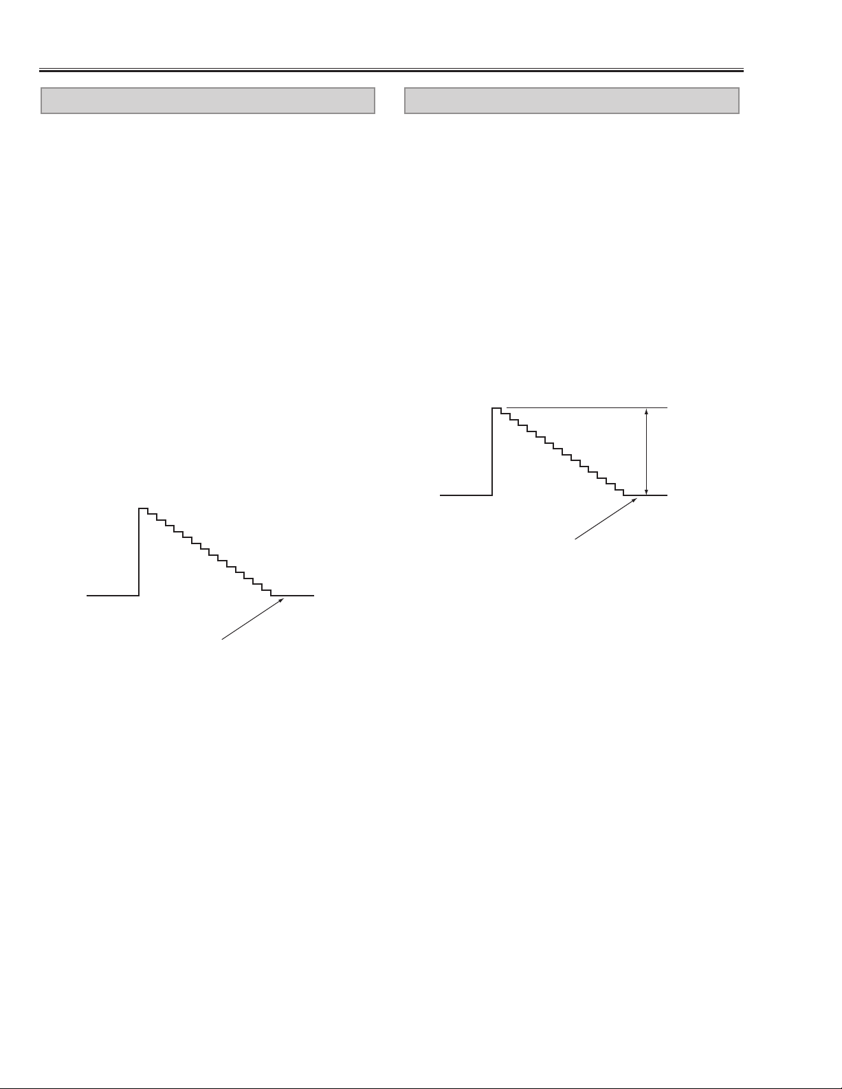
■ Waveforms
TP2101
A V VIDEO
TP6131
AV
V -SYNC
TP221R
A/D
R-INPUT
TP217
TP201
R-INPUT
TP218
TP202
G-INPUT
TP221G
A/D
G-INPUT
TP221B
A/D
B-INPUT
TP-219
TP203
B-INPUT
Page 43

-42-
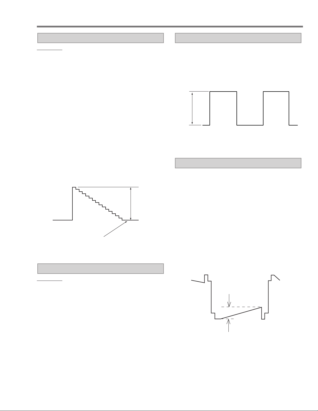
Waveforms
TP8253
V-SYNC
TP8254
H-SYNC
TP501
TP511
S&H
R-OUTPUT
TP2211R
D/A
R-OUTPUT
TP2221G
D/A
G-OUTPUT
TP502
TP512
S&H
G-OUTPUT
TP503
TP513
S&H
B-OUTPUT
TP2231B
D/A
B-OUTPUT
Page 44

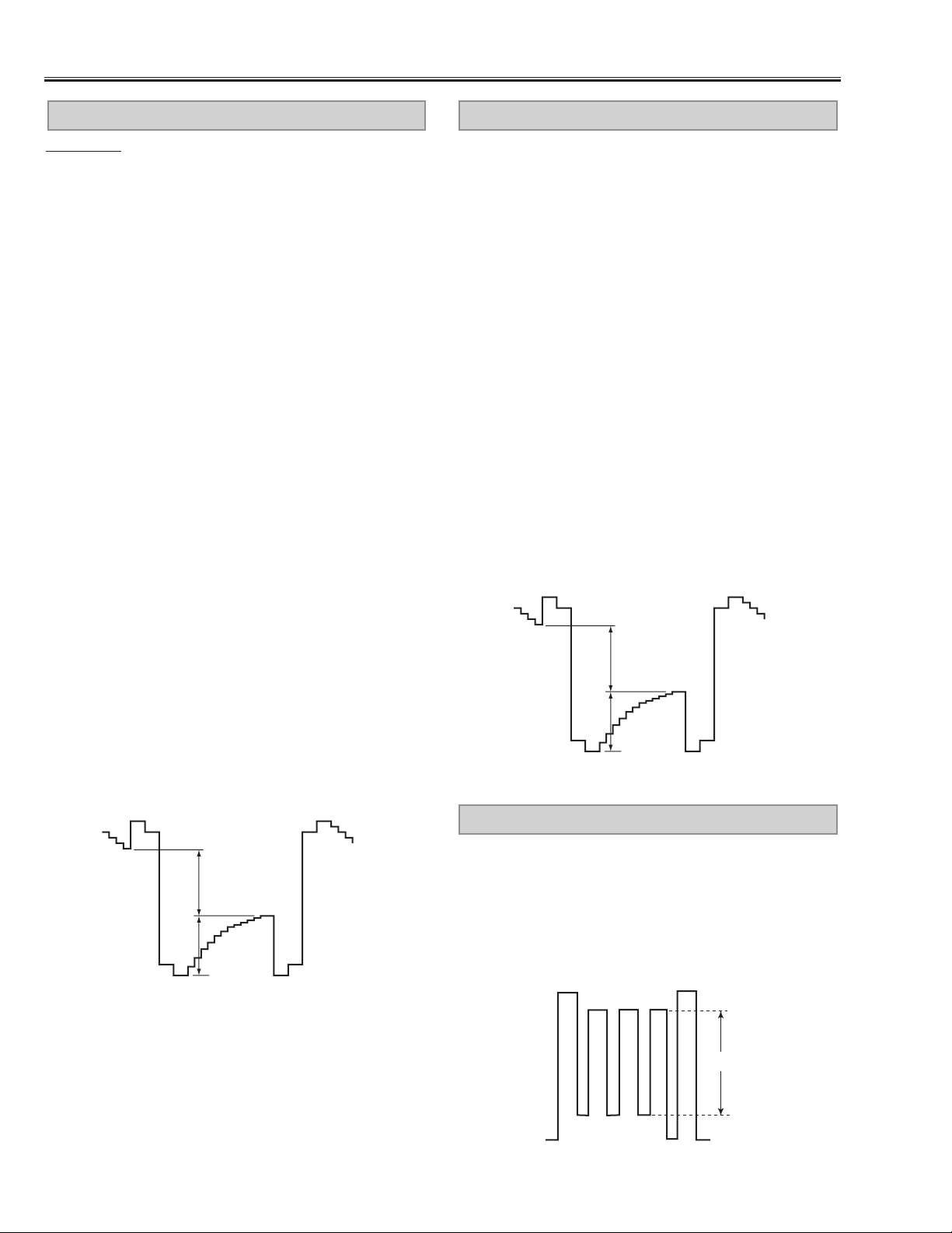
-43-
TPDVS
V-SYNC
TPDHS
H-SYNC
TP2571
NRS
Page 45

-44-
■ Cleaning
Cleaning with air spray
1. Remove the cabinet top following to “Mechanical
Disassemblies”.
2.Clean up the LCD panel and polarizing plate by using
the air spray from the cabinet top opening.
Caution:
Use a commercial (inert gas) air spray designed for
cleaning camera and computer equipment. Use a resinbased nozzle only. Be vary careful not to damage optical parts with the nozzle tip. Never use any kind of
cleanser on the unit. Also, never use abrasive materials
on the unit as this may cause irreparable damage.
After long periods of use, dust and other particles will accumulate on the LCD panel, prism, mirror, polarized glass,
lens, etc., causing the picture to darken or color to blur. If this occurs, clean the inside of optical unit.
Remove dust and other particles using air spray. If dirt cannot be removed by air spray, disassemble and clean
the optical unit.
Disassembly Cleaning
Disassembly cleaning method should only be performed when the unit is considerable dirty and cannot
be sufficiently cleaned by air spraying alone.
Be sure to readjust the optical system after performing disassembly cleaning.
1. Remove the cabinet top and main units following to
“Mechanical Disassemblies”.
2.Remove the optical base top f ollo wing to “Optical Unit
Disassemblies”. If the LCD panel needs cleaning,
remove the LCD panel unit following to “LCD panel
replacement”.
3. Clean the optical parts with a soft cloth. Clean
extremely dirty areas using a cloth moistened with
alcohol.
Caution:
The surface of the optical components consists of multiple dielectric layers with varying degrees of refraction.
Never use organic solvents (thinner, etc.) or any kind of
cleanser on these components.
Since the LCD panel is equipped with an electronic circuit, never use any liquids (water, etc.) to clean the unit.
Use of liquid may cause the unit to malfunction.
Page 46

-45-
■ IC Block Diagrams
● AV9155C <PLL, IC1301>
● AN5265 <AUDIO OUTPUT, IC001>
11
SCLK20-22
14.318MHz
crystal
14.318MHz
14.318MHz
19
20
2
3
13
14
REFERENCE
VDD
3
CLOCK
16
15
GND
CPU
CLOCK
PERIPHERAL
CLOCK
12
POWER-DOWN
OUTPUT
BUFFERS
OUTPUT
BUFFERS
9
AGND
17
2XCPU
18
CPU
10
OE
8
KBCLK
6
BUSCLK
7
FDCLK
1
COMMCLK
Page 47

-46-
IC Block Diagrams
● CXA2076Q <Video/Chroma, IC1101>
● CXA2016S <Sync Separator, IC3031>
SGND2
EXT SYNC IN48SYNCOUT51SOA50SCL49VM
56
2Vp-p
SUB CONT
SUB
CONT
SUB COLOR
ACC
DET
APC
VCO
61
62
X443
X358
VM OFF
TRAP
TRAP F0
COLOR SW
XTAL
TRAP OFF
PAL /
NTSC
HUE
HUE
64
FSCOUT
DL
TOTACC
TOT
PAL
ID
DEM
AXIS
1
SECAMREF
DL
6dB
EXT
SYNC
CV / YC
53CVIN
1Vp-p
VIDEO
IREF
43
IREF
SW
60
APCFIL
55YIN
57CIN
59SVcc1
20SVcc2
2SGND1
9
DCTRAN52BLHOLD45VSFIL46VSIN47HSIN
54
DC
SHARP
SHARP
NESS
PRE / OVER
KILLER
DET
fsc
ID
fsc R-Y
fsc B-Y
TRAN
DC
TRAN
CLP
DEM
3
D PICAGING
D PIC
5
4
YOUR
- (B-Y) OUT
- (R-Y) OUT
1Vp-p
6
YRET
V SYNC
SEP
Y / C
MIX
COLOR
& AXIS
7
- (R-Y) IN
COL
8
- (B-Y) IN
H SYNC
YS1 OFF
11
YS1
SEP
V FREQ
50 / 60 ID
YS
SW
CLP
13
12
R1IN
INTER
-LACE
G1IN
14
GATE
B1IN
AFCFIL41CERA38AFCPIN /
40
PHASE
DET.
GATE
INTERLACE
YS / YM
SW
CLP
19
18
17
16YM15
YS2
R2IN
G2IN
B2IN
H
32f
VCO
1 / 32
2fH
C MODE
Count Down
525 / 625
PIC
PIC
OSD
MIX
DIG
PHASE
PHASE
SHIFT
H POSI
AFC
D-COL
DET
COL
HOFF
D-
Send
Castle
`
`
29
BRT
BRT
ABL
ABLFIL
L2FIN
39
H.DRIVE
SCP BGR / BGF
VPOSI,VOFF
VSIZE
GB DRV
GB
DRV
HV
COMP
EHT H,V
28
ABLIN/
VCOMP
WIDE
Sawtooth
Gen.
VLIN,SCORR
WIDE
parabola
Gen.
GB CUT
CUT
OFF
AKB
252321
RSH
GSH
BLK
AKB OFF
BSH
36
DVcc1
4442DVcc2
DGND
37 HD OUT
10 SCPOUT
30 VTIM
34 VAGCSH
35 SAWOSC
VD+OUT
32
/VPROT
VD-OUT
31
/VPROT
33 E-WOUT
22 R OUT
24 G OUT
26 B OUT
27
IKIN
Page 48

-47-
IC Block Diagrams
● CXA2111R <LCD Driver, IC401>
● CXA2112R <Sample & Hold, IC501, IC531, IC561, IC6501, IC6531, IC6551>
Page 49

-48-
IC Block Diagrams
● CXD3503R <White Uniformity Compensation, IC471>
● FA5331M <Power Factor Control, IC01>
Page 50

-49-
IC Block Diagrams
● IDT71V016S <RAM, IC805>
● LA7217M <Sync. Separator, IC6131>
Page 51

-50-
IC Block Diagrams
● LB1641<Motor Drive, IC5501, IC5551>
● LC4105V <Buffer, IC2501, IC2521, IC2541>
Page 52

-51-
IC Block Diagrams
● M62358FP <DAC, IC431>
● MB40988PFQ<D/A COnverter, IC2200>
Page 53

-52-
IC Block Diagrams
● MC14538BF <IC7201>
● MPC948FA <Clock Driver, IC1302>
Page 54

-53-
IC Block Diagrams
● PW264 <System Control & Scan Converter, IC301>
● STR-Z2156 <Power SWitching Control, IC631>
Page 55

-54-
●TC9090AF <3-Line Y/C Separator, IC2101>
●TC4053BP <Switching, IC101, IC3001, IC3002, IC3571, IC5001, IC5282,
IC6101,IC6151>
IC Block Diagrams
Page 56

-55-
IC Block Diagrams
●TDA8395T <SECAM Decoder, IC161>
●TDA4665T <1H Delay Line, IC181>
±(R-Y)
colour-difference
input signals
±(B-Y)
Vp1
Sandcastle
pulse input
16
14
9
5
SIGNAL
CLAMPIMG
SIGNAL
CLAMPIMG
analogure supply
SANDCASTLE
DETECTOR
TDA4665
10 1
Gnd1
pre-amplifiers
FREQUENCY
DETECTOR
PHASE
LINE
MEMORY
LINE
MEMORY
DIVIDER
BY 192
LP
digital supply
Vp2
SAMPLE
AND
HOLD
SAMPLE
AND
HOLD
3MHz shifting clock
6MHz
CCO
LP
Addition
stage
LP
DIVIDER
BY 2
output
buffers
Gnd2
11
±(R-Y)
colour-difference
output signals
12
±(B-Y)
3
CVBS
16
BANDGAP
ACC
INTERFACE
1
f ref./IDENT
CLOCHE ref.
5
TUNING
CLOCHE
CONTROL
15
SAND
PLL ref. GND
8
362
TUNING
TDA8395
PLL
IDENT
DEEMPHASIS
SWITCHING
TESTVp
910-(R-Y)
-(B-Y)
Page 57

-56-
●TDA9178T <Picture Improvement, IC121>
IC Block Diagrams
Page 58

-57-
■ Pin description of diode, transistor and IC
● Diode
● Transistor/FET
● IC
FET
● Diode
K
A
● Transistor/FET
K
A
K
AA
A
KK
K
A
K
K: Cathode
A: Anode
A
C
B
C
E
● IC
1
Index
C1
3
2
E
C2
Vdd
1
C1
C2
B1 B2
E
B2
GND
C
E
2
C
E
B
C
3
E
B
B
2
3
1
E
C1
CBE
C2
B2
E
3
2
C
B
B1
1
C
BE
B1
RESET
Index
1
2
N
1
2
N
C2
E2 C1
B1
B2
B1
B2
(IN)
E1
1
(GND)
2
4
5
6
Index
E1
C1
C2
E2
3
(OUT)
C: Collector
B: Base
E: Emitter
G
3
2
1
Index
D: Drain
G: Gate
S: Source
S
G
D
S
D
3
21
5
4
Index
N
1
Index
Index
Index
N
1
N
1
N
1
Index
N
1
N
1
Index
Page 59

-58-
■ Par ts description and reading in schematic diagram
1. The parts specification of resistors, capacitors and
coils are expressed in designated code.Please check
the parts description by the following code table.
2. Some of transistors and diodes are indicated in mark
for the substitution of parts name. Please check the
parts name by the following code table.
3.V oltages and wa vef orms were taken with a video color
bar signal(1Vp-p at 75 ohms terminated) and controls
to normal.
4. Voltages were taken with a high-impedance digital
voltmeter.
Example 2000 K K 1000 BG
Characteristic
Example 160 E M 10
Capacitance value
Tolerance
Type
Rated voltage
Excepting electric capacitors, all
capacitance values of less than 1
are expressed in µF and more
than 1 are in pF.
Example L2 C1 4R7 K N
Tolerance
Inductance value
Manufacture code
Unique code
Mark Material
E Electrolytic
P Electrolytic (non-polar ized)
C Ceramic (temperature compensation)
K Ceramic
F Polyester
N Polypropylene
M Metalized polypropylene
H Metalized polypromylar
B Ceramic (semiconductor)
G Metalized polyestel
Y Composite film
S Styrol
T Tantalum oxide solid electrolytic
U Organic semiconductive electrolyte
D Electric double layer electrolytic
Mark Tolerance
A not specified
B ±0.1
C ±0.25
D ±0.5
F±1
G±2
E ±2.5
H±3
J±5
K±0
M ±20
N ±30
P +100 -0
Q +30 -10
T +50 -10
U +75 -10
V +20 -10
W +100 -10
X +40 -20
Y +150 -10
Z +80 -20
Mark Tolerance (nH) Mark Tolerance (%)
C ±0.25 G ±2
D ±0.5 J ±5
S ±0.3 K ±10
A ±0.2 L ±15
M ±20
Coil Reading
Capacitor Reading
Example 1/2 D J 10K B
Example 6 W K 8.2
Example 1/2 C K 1M
Resistor Reading
Characteristic
Z (Carbon fuse)
B (Non-burnable)
Resistance value
Tolerance (see below table)
Material (see below table)
Rated wattage (W)
K indicates in KΩ
M indicate in MΩ
Note: Resistor which is indicated with resistance value only are
1/6W carbon resistor.Resistor which is indicated with material, tolerance and value are 1/4W rated wattage.
Mark Material
D Carbon
N Metal film
S Oxide metal film
C Solid
G Metal glaze
W Wire wounding or cement
H Ceramic
F Fusible
Mark Tolerance
A ±0.05
B ±0.1
C ±0.25
D ±0.5
F±1
G±2
J±5
K ±10
M ±20
P +5 -15
Z used in 0 ohm
● Material table
● Tolerance table
● Material table
● Tolerance table
Mark Type number
R 1S2076A,1S2473,1N4148
AA 1S2076A,1S2473,1SS133,1N4148
● Diode
Mark Type number
-- 2SC536 2SC945A 2SC1815 2SC1740S
AD NF, NG PA, QA, RA Y, GR Q, R, S
AE NF, NG PA, QA O, Y, GR Q, R, S
● Transistor
(1) NPN type
Diode/Transistor Type Reading
Mark Type number
-- 2SA608 2SA564A 2SA1015 2SA933S
AB NF R Y, GR R
AC NF Q, R O, Y, GR Q, R
(2) PNP type
Mark Type number
-- 2SA1179 2SA1037K 2SA1037AK 2SC2812 2SC2412K
AJ M6, M7 R, S R, S
AH L6, L7 R, S
(3) Chip type
Page 60

-59-
■ Electrical Parts List
Product safety should be considered when a component replacement is made in any area of a projector.
Components indicated by a mark in this parts list and the circuit diagram show components whose value have
special significance to product safety. It is particularly recommended that only parts specified on the following parts
list be used for components replacement pointed out by the mark.
!
● Read Description in the parts list
Read description in the Capacitor and Resistor as follows:
CAPACITOR
CERAMIC 100P K 50V
Rated Voltage
Tolerance Symbols:
Less than 10pF
A : Not specified B : ±0.1pF C : ±0.25pF
D : ±0.5pF E : +0 -1pF F : ±1PF
G : ±2pF H : +0.1 -0pF L : +0 -0.1pF
R : ±0.25 -0pF S : +0-0.25pF
More than 10pF
A : Not specified B : ±0.1% C : ±0.25%
D : ±0.5% F : ±1% G : ±2%
H : ±3% J : ±5% K : ±10%
L : ±15% M : ±20% N : ±30%
P : +100-0% Q : +30-10% T : +50-10%
U : +75-10% V : +20-10% W : +100-10%
X : +40-20% Y : +150-10% Z : +80-20%
Rated value: P=pico farad, U=micro farad
Material:
CERAMIC...........Ceramic
MT-PAPER.........Metallized Paper
POLYESTER......Polyester
MT-POLYEST.....Metallized Polyester
POLYPRO..........Polypropylene
MT-POLYPRO....Metallized Polypropylene
COMPO FILM.....Composite film
MT-COMPO........Metallized Composite
STYRENE...........Styrene
TA-SOLID...........Tantalum Oxide Solid Electrolytic
AL-SOLID...........Aluminium Solid Electrolytic
ELECT................Aluminum Foil Electrolytic
NP-ELECT..........Non-polarised Electrolytic
OS-SOLID.......... Aluminium Solid with Organic Semiconductive Electrolytic
POS-SOLID........Polymerized Organic Semiconductive
DL-ELECT..........Double Layered Electrolytic
PPS-FILM...........Polyphenylene Sulfide Film
MT-PPS-FILM.....Metalized Polyphenylene Sulfide Film
MT-PEN-FILM.....Metalized Polyethylenenaphthalate Film
CAPACITOR.......Other
RESISTOR
CARBON 4.7K J A 1/4W
Performance Symbols:
A: General B: Non flammable Z: Low noise
Other: Temperature coefficient
T: ±10ppm/°C U: ±25ppm/°C C: ±50ppm/°C
D: ±100ppm/°C E: ±200ppm/°C F: ±250ppm/°C
G: ±350ppm/°C H: ±1000ppm/°C±10% W: ±1200ppm/°C±10%
Y: ±1400ppm/°C±10% J: ±2000ppm/°C±10% K: ±2400ppm/°C±10%
L: ±2700ppm/°C±10% M: ±3000ppm/°C±10% N: ±3300ppm/°C±10%
P: ±3600ppm/°C±10% Q: ±3900ppm/°C±10% R: ±4200ppm/°C±10%
S: ±4300ppm/°C±10% V: ±4500ppm/°C±10% X: ±8000ppm/°C±10%
Tolerance Symbols:
A: ±0.05% B: ±0.1% C: ±0.25% D: ±0.5%
F: ±1% G: ±2% J: ±5% K: ±10%
M: ±20% P: +5-15% Z: 0 ohm
Rated value, ohms:
Material:
CARBON........... Carbon
MT-FILM............ Metal Film
OXIDE-MT......... Oxide Metal Film
SOLID................ Composition
MT-GLAZE.........Metal Glaze
WIRE WOUND...Wire Wound
CERAMIC RES.. Ceramic
FUSIBLE RES....Fusible
RESISTOR ........Other
K: 1,000, M: 1,000,000
Rated Wattage
Page 61

Electrical Parts List
-60-
● OUT OF CIRCUIT BOARD
W901
Viewer Unit
FN901
Cooling Fan
A901
Lamp Ballast
Unit
Main Comp-A
Board
F601
Fuse
Filter Board
SW902
Thermal switch
AV BOARD
SW901
Thermal switch
Main Comp-D
Board
Note: Parts order must contain Service Ref. No., Part No., and Descriptions.
FN905
Coolong Fan
FN904
Coolong Fan
SW904
Interlock switch
EL903B
B-LCD Panel
EL901G
G-LCD Panel
EL902R
R-LCD Panel
Page 62

OUT OF CIRCUIT BOARDS
LP900 610 280 6939 LAMP ASSY (POA-LMP21J)
L901 645 003 3810 CORE,FERRITE
L902 645 003 3834 CORE,FERRITE
L903 645 003 3834 CORE,FERRITE
L904 645 003 3810 CORE,FERRITE
MISCELLANEOUS
A901 645 036 4655 UNIT,BALLAST
EL901G 645 039 2979 LCD(P09XG250(G))
645 039 2948 LCD(P09XG260(G))
EL902R 645 039 2986 LCD(P09XG260(R))
645 039 2955 LCD(P09XG250(R))
EL903B 645 039 2993 LCD(P09XG260(B))
645 039 2962 LCD(P09XG250(B))
FN901 645 038 1577 MOTOR,FAN DC 1.4W
FN902 645 038 1591 MOTOR,FAN DC 2.2W
FN903 645 038 1591 MOTOR,FAN DC 2.2W
FN904 645 038 1584 MOTOR,FAN DC 2.04W
FN905 645 038 1584 MOTOR,FAN DC 2.04W
SP901 645 030 6150 SPEAKER,8
SW901 645 039 7301 SWITCH,REED
SW902 645 026 5457 SWITCH,THERMAL
SW904 645 024 8986 SWITCH,PUSH 2P-2TX2
W901 645 039 2245 UNIT,VIEWER
610 286 1556 ASSY,PWB,POWER MB6A
1AA0B10C225AA
TRANSISTOR
Q641 405 002 0308 TR 2SA1037K T146 R
Q661 405 014 4509 TR 2SC2412K T146 R
Q662 405 014 4509 TR 2SC2412K T146 R
Q663 405 014 4509 TR 2SC2412K T146 R
Q67A 405 014 4509 TR 2SC2412K T146 R
Q671 405 138 1309 TR 2SB1565-E
405 138 1408 TR 2SB1565-F
Q672 405 014 4509 TR 2SC2412K T146 R
Q68A 405 014 4509 TR 2SC2412K T146 R
Q681 405 156 0209 TR 2SK2376
Q686 405 002 0308 TR 2SA1037K T146 R
Q69A 405 014 4509 TR 2SC2412K T146 R
Q691 405 014 4509 TR 2SC2412K T146 R
INTEGRATED CIRCUIT
IC001 409 073 1509 IC AN5265
IC5501 409 114 4803 IC LB1641
IC5551 409 114 4803 IC LB1641
IC631 409 421 4701 IC STR-Z2156
IC656 409 344 6509 IC UPC1093T-E1
IC66A 409 461 7809 IC PQ20WZ11
IC67A 409 461 7809 IC PQ20WZ11
IC68A 409 461 7809 IC PQ20WZ11
IC69A 409 461 7809 IC PQ20WZ11
CAPACITOR
C001 403 148 0305 ELECT 470U M 16V
C002 403 049 0008 ELECT 1U M 50V
C003 403 049 0008 ELECT 1U M 50V
C004 403 044 9501 ELECT 100U M 25V
C005 403 041 8804 ELECT 10U M 16V
C006 403 044 9501 ELECT 100U M 25V
C007 403 070 2606 CERAMIC 0.1U Z 50V
C008 403 044 9501 ELECT 100U M 25V
C5501 403 148 0305 ELECT 470U M 16V
C5502 403 069 9500 CERAMIC 0.01U Z 50V
C5503 403 069 9500 CERAMIC 0.01U Z 50V
C5551 403 148 0305 ELECT 470U M 16V
C5552 403 069 9500 CERAMIC 0.01U Z 50V
C5553 403 069 9500 CERAMIC 0.01U Z 50V
C63A 403 323 8706 MT-POLYEST 0.047U K 450V
C630 403 156 9000 ELECT 2.2U M 50V
C631 403 237 7901 MT-COMPO 0.22U J 50V
C632 403 069 1702 CERAMIC 1000P K 50V
C633 403 165 8803 CERAMIC 330P K 2K
C634 403 070 2606 CERAMIC 0.1U Z 50V
C635 403 167 8603 CERAMIC 220P K 2K
C636 403 083 4307 POLYPRO 0.022U J 400V
C637 403 074 9502 CERAMIC 680P K 50V
C638 403 156 8805 ELECT 1U M 50V
C639 403 148 1807 ELECT 220U M 35V
C640 403 070 2606 CERAMIC 0.1U Z 50V
C641 403 269 5906 CERAMIC 0.22U K 16V
C642 403 070 2606 CERAMIC 0.1U Z 50V
C643 403 166 9809 TA-SOLID 0.47U M 25V
C648 404 059 9203 CERAMIC 1000P M 400V
C649 404 059 9203 CERAMIC 1000P M 400V
C651 403 350 5006 ELECT 1000U M 25V
C652 403 350 5303 ELECT 3900U M 10V
C653 403 155 5607 ELECT 220U M 10V
C654TM 403 076 2006 CERAMIC 330P K 500V
C655TM 403 076 2006 CERAMIC 330P K 500V
C656 403 256 0808 MT-COMPO 0.47U J 50V
C66A 403 069 9500 CERAMIC 0.01U Z 50V
C66B 403 069 9500 CERAMIC 0.01U Z 50V
C66C 403 148 0305 ELECT 470U M 16V
C67A 403 069 9500 CERAMIC 0.01U Z 50V
C67B 403 069 9500 CERAMIC 0.01U Z 50V
C67C 403 148 0305 ELECT 470U M 16V
C671 403 047 5005 ELECT 470U M 25V
C676 403 069 9500 CERAMIC 0.01U Z 50V
C68A 403 069 9500 CERAMIC 0.01U Z 50V
C68B 403 069 9500 CERAMIC 0.01U Z 50V
C68C 403 148 0305 ELECT 470U M 16V
C683 403 038 2006 ELECT 100U M 6.3V
C685 403 038 2006 ELECT 100U M 6.3V
C687 403 038 2006 ELECT 100U M 6.3V
C69A 403 069 9500 CERAMIC 0.01U Z 50V
C69B 403 069 9500 CERAMIC 0.01U Z 50V
C69C 403 148 0305 ELECT 470U M 16V
C691 403 042 3006 ELECT 100U M 16V
C692 403 042 3006 ELECT 100U M 16V
C694 403 042 3006 ELECT 100U M 16V
C695 403 042 3006 ELECT 100U M 16V
RESISTOR
R001 401 037 5004 MT-GLAZE 0.000 ZA 1/10W
R002 401 037 9309 MT-GLAZE 18K JA 1/10W
R003 401 037 7909 MT-GLAZE 1.5K JA 1/10W
R004 401 038 2200 MT-GLAZE 27K JA 1/10W
R005 401 110 8601 MT-GLAZE 1 JA 1/10W
R006 401 037 5400 MT-GLAZE 1K JA 1/10W
R007 401 069 0305 OXIDE-MT 6.8 JA 2W
401 069 0404 OXIDE-MT 6.8 JA 2W
R008 401 037 9101 MT-GLAZE 180 JA 1/10W
R011 401 037 5004 MT-GLAZE 0.000 ZA 1/10W
R012 401 037 5004 MT-GLAZE 0.000 ZA 1/10W
R5501 401 038 3603 MT-GLAZE 3.3K JA 1/10W
R5502 401 038 3603 MT-GLAZE 3.3K JA 1/10W
R5503 401 037 5400 MT-GLAZE 1K JA 1/10W
R5504 401 037 5004 MT-GLAZE 0.000 ZA 1/10W
R5506 401 037 5004 MT-GLAZE 0.000 ZA 1/10W
!!!!!!!!!
!
Ref. No. Part No. Description Ref. No. Part No. Description
-61-
Electrical Parts List
Page 63

R5507 401 037 5004 MT-GLAZE 0.000 ZA 1/10W
R5551 401 038 3603 MT-GLAZE 3.3K JA 1/10W
R5552 401 038 3603 MT-GLAZE 3.3K JA 1/10W
R5553 401 037 5400 MT-GLAZE 1K JA 1/10W
R5554 401 037 5004 MT-GLAZE 0.000 ZA 1/10W
R5556 401 037 5004 MT-GLAZE 0.000 ZA 1/10W
R5557 401 037 5004 MT-GLAZE 0.000 ZA 1/10W
R63A 401 275 2902 MT-GLAZE 68K JA 1W
R63B 401 275 2902 MT-GLAZE 68K JA 1W
R631 401 069 4402 OXIDE-MT 68K JA 2W
R632 401 069 4402 OXIDE-MT 68K JA 2W
R633 402 079 7803 FUSIBLE RES 22 JH 1/4W
R634 401 238 4509 MT-GLAZE 47 JA 1/3W
R635 401 037 5400 MT-GLAZE 1K JA 1/10W
R636 401 257 7406 MT-GLAZE 120 JA 1/3W
R637 401 037 5608 MT-GLAZE 10K JA 1/10W
R638 401 037 5202 MT-GLAZE 100 JA 1/10W
R639 401 105 9705 MT-GLAZE 220 JA 1/3W
R641 401 037 5400 MT-GLAZE 1K JA 1/10W
R642 401 037 5707 MT-GLAZE 100K JA 1/10W
R643 401 037 8005 MT-GLAZE 15K JA 1/10W
R644 401 038 0909 MT-GLAZE 220K JA 1/10W
R645 401 038 9308 MT-GLAZE 68K JA 1/10W
R646 401 038 9209 MT-GLAZE 6.8K JA 1/10W
R654 401 038 2002 MT-GLAZE 270 JA 1/10W
R655 401 037 5400 MT-GLAZE 1K JA 1/10W
R656 401 037 5608 MT-GLAZE 10K JA 1/10W
R657 401 038 9209 MT-GLAZE 6.8K JA 1/10W
R658 401 037 5103 MT-GLAZE 10 JA 1/10W
R659 401 037 5400 MT-GLAZE 1K JA 1/10W
R66F 401 037 5004 MT-GLAZE 0.000 ZA 1/10W
R66G 401 038 3603 MT-GLAZE 3.3K JA 1/10W
R66H 401 038 5102 MT-GLAZE 3.9K JA 1/10W
R66J 401 038 0107 MT-GLAZE 2K JA 1/10W
R660 401 038 3504 MT-GLAZE 330 JA 1/10W
R661 401 037 5608 MT-GLAZE 10K JA 1/10W
R662 401 037 6803 MT-GLAZE 12K JA 1/10W
R663 401 038 9209 MT-GLAZE 6.8K JA 1/10W
R664 401 037 7909 MT-GLAZE 1.5K JA 1/10W
R665 401 038 0701 MT-GLAZE 2.2K JA 1/10W
R666 401 037 9309 MT-GLAZE 18K JA 1/10W
R667 401 038 0701 MT-GLAZE 2.2K JA 1/10W
R67D 401 102 7506 MT-GLAZE 22 JA 1W
R67E 401 198 7701 MT-GLAZE 33 JA 1W
R67G 401 038 3603 MT-GLAZE 3.3K JA 1/10W
R67H 401 038 5102 MT-GLAZE 3.9K JA 1/10W
R67J 401 038 0107 MT-GLAZE 2K JA 1/10W
R67K 401 037 8005 MT-GLAZE 15K JA 1/10W
R67L 401 038 7809 MT-GLAZE 56K JA 1/10W
R67M 401 037 5608 MT-GLAZE 10K JA 1/10W
R671 401 238 4400 MT-GLAZE 2.7K JA 1/3W
R672 401 238 4202 MT-GLAZE 1.5K JA 1/3W
R673 401 038 7809 MT-GLAZE 56K JA 1/10W
R674 401 037 5707 MT-GLAZE 100K JA 1/10W
R68A 401 162 6501 MT-GLAZE 82 JA 1W
R68B 401 162 6501 MT-GLAZE 82 JA 1W
R68C 401 162 6501 MT-GLAZE 82 JA 1W
R68D 401 203 1106 MT-GLAZE 8.2 JA 1W
R68E 401 203 1106 MT-GLAZE 8.2 JA 1W
R68G 401 038 1302 MT-GLAZE 2.4K JA 1/10W
R68H 401 038 5102 MT-GLAZE 3.9K JA 1/10W
R68J 401 038 0107 MT-GLAZE 2K JA 1/10W
R68K 401 038 9209 MT-GLAZE 6.8K JA 1/10W
R68L 401 038 7809 MT-GLAZE 56K JA 1/10W
R68M 401 037 5608 MT-GLAZE 10K JA 1/10W
R681 401 038 0800 MT-GLAZE 22K JA 1/10W
R682 401 037 5707 MT-GLAZE 100K JA 1/10W
R686 401 038 0800 MT-GLAZE 22K JA 1/10W
R69D 401 102 7407 MT-GLAZE 10 JA 1W
R69E 401 102 7407 MT-GLAZE 10 JA 1W
R69G 401 038 5102 MT-GLAZE 3.9K JA 1/10W
R69H 401 038 5102 MT-GLAZE 3.9K JA 1/10W
R69J 401 038 0107 MT-GLAZE 2K JA 1/10W
R69K 401 038 3702 MT-GLAZE 33K JA 1/10W
R69L 401 038 7809 MT-GLAZE 56K JA 1/10W
R69M 401 037 5608 MT-GLAZE 10K JA 1/10W
R69PTM 401 026 4308 CARBON 3.3K JA 1/6W
R691 401 037 5608 MT-GLAZE 10K JA 1/10W
R692 401 037 5608 MT-GLAZE 10K JA 1/10W
R693 401 037 5608 MT-GLAZE 10K JA 1/10W
R694 401 037 5608 MT-GLAZE 10K JA 1/10W
R695 401 037 5608 MT-GLAZE 10K JA 1/10W
R696 401 038 7700 MT-GLAZE 5.6K JA 1/10W
R697 401 037 5004 MT-GLAZE 0.000 ZA 1/10W
TRANSFORMER
T651 645 030 7126 TRANS,POWER,PULSE
COIL
L671 645 007 8125 INDUCTOR,47U K
L683 645 007 8118 INDUCTOR,390U K
L685 645 007 7975 INDUCTOR,100U K
L687 645 007 8125 INDUCTOR,47U K
DIODE
D001 407 058 0509 ZENER DIODE RD9.1M-T2BB2
407 058 0608 ZENER DIODE RD9.1M-T2BB3
407 190 6209 ZD 02CZ9.1Y(TE85R)
407 190 3505 ZD 02CZ9.1Z(TE85R)
D002 407 071 6502 ZENER DIODE DZD5.1Y-TA
407 175 3407 ZD 02CZ5.1Y(TE85R)
D5501 407 217 0302 ZD 02CZ3.6X(TE85R)
407 175 3100 ZD 02CZ3.6Z(TE85R)
D5551 407 071 6502 ZENER DIODE DZD5.1Y-TA
407 175 3407 ZD 02CZ5.1Y(TE85R)
D631 407 071 0104 ZENER DIODE DZD12Y-TA
407 054 4204 ZENER DIODE RD12M-T2BB2
407 175 2806 ZD 02CZ12Y(TE85R)
D632 407 190 4106 DIODE SFPL-52V
D633 407 100 6909 DIODE AG01
D634 407 125 5307 ZENER DIODE RD27M-T1BB
407 140 0608 ZENER DIODE 02CZ27-TE85L
D635 407 190 4106 DIODE SFPL-52V
D636 407 149 0807 DIODE 1SS355-TE-17
D641 407 149 0807 DIODE 1SS355-TE-17
D642 407 056 9306 ZENER DIODE RD5.1M-T1BB2
407 056 9405 ZENER DIODE RD5.1M-T2BB3
D651 407 202 9808 DIODE FMB-26L
D651B 411 174 4808 SCR S-TPG PAN+SWW 3X8
D651H 610 273 6472 HEAT SINK C-M6RA
D652 407 164 2206 DIODE FMB-24L
D652B 411 174 4808 SCR S-TPG PAN+SWW 3X8
D653 407 190 4106 DIODE SFPL-52V
D656 407 071 7806 ZENER DIODE DZD6.8Z-TA
D660 407 101 5109 ZD 02CZ4.7Y(TE85R)
D661 407 149 0807 DIODE 1SS355-TE-17
D662 407 149 0807 DIODE 1SS355-TE-17
D663 407 149 0807 DIODE 1SS355-TE-17
D664 407 149 0807 DIODE 1SS355-TE-17
D665 407 149 0807 DIODE 1SS355-TE-17
D666 407 149 0807 DIODE 1SS355-TE-17
D667 407 149 0807 DIODE 1SS355-TE-17
D668 407 149 0807 DIODE 1SS355-TE-17
D669 407 149 0807 DIODE 1SS355-TE-17
D691 407 004 0706 DIODE DCB015-TB
!
!
Ref. No. Part No. Description Ref. No. Part No. Description
Electrical Parts List
-62-
Page 64

D692 407 004 0706 DIODE DCB015-TB
D693 407 004 0706 DIODE DCB015-TB
MISCELLANEOUS
PC641 408 039 3502 PC TLP721F(D4-GB)
PC642 408 039 3502 PC TLP721F(D4-GB)
PC643 408 039 3502 PC TLP721F(D4-GB)
PC644 408 039 3502 PC TLP721F(D4-GB)
610 284 5198 ASSY P.F.C.MA6A SERVICE
1AASB10C2250B
ASSY,PWB,P.F. MA6A
TRANSISTOR
Q611 405 140 3704 TR 2SK2698
CAPACITOR
C611 403 165 6007 CERAMIC 1000P K 1K
C612 403 165 6007 CERAMIC 1000P K 1K
C613 403 126 4608 ELECT 100U M 25V
C616 403 275 6003 MT-POLYEST 1.5U J 400V
C617 403 119 8002 ELECT 470U M 25V
C618 404 081 6003 ELECT 150U M 450V
C619 403 323 8706 MT-POLYEST 0.047U K 450V
RESISTOR
R611 401 105 9705 MT-GLAZE 220 JA 1/3W
R612 402 079 1900 RESISTER 0.22 JA 2W
R613 402 079 1900 RESISTER 0.22 JA 2W
R614 401 237 0007 MT-GLAZE 47K JA 1W
R615 401 237 0007 MT-GLAZE 47K JA 1W
R616 401 237 0007 MT-GLAZE 47K JA 1W
R617 401 237 0007 MT-GLAZE 47K JA 1W
R618 401 038 5508 MT-GLAZE 4.7 JA 1/10W
R620 401 242 3901 MT-GLAZE 240K JA 1/2W
R621 401 242 3901 MT-GLAZE 240K JA 1/2W
R622 401 259 9002 MT-GLAZE 150K FA 1/2W
R623 401 259 9002 MT-GLAZE 150K FA 1/2W
R624 401 259 9002 MT-GLAZE 150K FA 1/2W
R625 401 259 9002 MT-GLAZE 150K FA 1/2W
COIL
L611 645 039 9749 INDUCTOR,1800U
L615TM 610 031 9998 PIPE CORE
DIODE
DB611 407 202 7705 DIODE D10XB60
DB611B 411 001 8900 SCR BIN 3X8
DB611H 610 281 2275 HEAT SINK B-MA6A
DB611H1 645 022 0081 SPACER
DS611 407 175 2400 THYRISTOR CR12AM-12
DS611B 411 174 4808 SCR S-TPG PAN+SWW 3X8
D611 407 174 2302 DIODE AK06
D612 407 191 3900 DIODE FML-G16S
D612B 411 174 4808 SCR S-TPG PAN+SWW 3X8
MISCELLANEOUS
TSW611 645 027 4145 SWITCH,THERMAL
645 031 0256 THERMOSTATS
TSW611B 411 179 6203 SCR S-TPG PAN+SWW 3X6
FB611 610 229 3531 CORE
FB612 610 229 3531 CORE
PTH611 408 037 5607 THERMISTOR NTH11D8R0LC
ASSY,PWB,HIC MA6A
TRANSISTOR
Q01 405 014 4509 TR 2SC2412K T146 R
Q02 405 002 0308 TR 2SA1037K T146 R
INTEGRATED CIRCUIT
IC01 409 406 7000 IC FA5331M
CAPACITOR
C01 403 074 9502 CERAMIC 680P K 50V
C02 403 075 2304 CERAMIC 0.068U Z 50V
C03 403 070 2606 CERAMIC 0.1U Z 50V
C04 403 030 7009 CERAMIC 68P J 50V
C05 403 069 5601 CERAMIC 0.01U K 50V
C06 403 073 7301 CERAMIC 470P K 50V
C07 403 073 1200 CERAMIC 0.033U K 50V
C08 403 072 3403 CERAMIC 0.022U Z 50V
C10 403 070 2606 CERAMIC 0.1U Z 50V
C11 403 070 2606 CERAMIC 0.1U Z 50V
RESISTOR
R01 401 038 0800 MT-GLAZE 22K JA 1/10W
R02 401 037 5608 MT-GLAZE 10K JA 1/10W
R03 401 037 9507 MT-GLAZE 1.8M JA 1/10W
R04 401 038 0503 MT-GLAZE 22 JA 1/10W
R05 401 037 5004 MT-GLAZE 0.000 ZA 1/10W
R06 401 037 5004 MT-GLAZE 0.000 ZA 1/10W
R07 401 038 3504 MT-GLAZE 330 JA 1/10W
R08 401 037 5202 MT-GLAZE 100 JA 1/10W
R09 401 037 7909 MT-GLAZE 1.5K JA 1/10W
R11 401 038 6604 MT-GLAZE 470K JA 1/10W
R12 401 038 0909 MT-GLAZE 220K JA 1/10W
R13 401 148 2701 MT-GLAZE 1.1K FA 1/10W
R14 401 092 3304 MT-GLAZE 1.2K FA 1/10W
VARIABLE RESISTOR
VR01 645 041 5333 VR,SEMI,1K M
DIODE
D01 407 004 1000 DIODE DCC010-TB
D02 407 004 1000 DIODE DCC010-TB
610 280 5833 ASSY,PWB,LINE FILTER MA6A
1AA0B10C2250C
CAPACITOR
C601 404 081 4702 MT-POLYEST 0.22U M 275V
C602 404 081 4702 MT-POLYEST 0.22U M 275V
C603 404 081 4702 MT-POLYEST 0.22U M 275V
C604 404 081 4702 MT-POLYEST 0.22U M 275V
C606 404 059 9203 CERAMIC 1000P M 400V
RESISTOR
R601 401 008 8607 CARBON 220K JA 1/2W
VARIABLE RESISTOR
VA601 408 018 9808 VARISTOR ENC471D-14AS
COIL
L601 645 025 7827 LINE FILTER
L602 645 025 7827 LINE FILTER
MISCELLANEOUS
F601 423 022 2102 FUSE 250V 4A
F601A 645 000 5077 HOLDER,FUSE
F601B 645 000 5077 HOLDER,FUSE
K601 645 000 2793 SOCKET,INLET AC
!!!!!!!!!!!!!!!!!
!
Ref. No. Part No. Description Ref. No. Part No. Description
-63-
Electrical Parts List
Page 65

610 281 8123 ASSY,PWB,R/C MA6A
1AA0B10C2250D
CAPACITOR
C2851 403 316 5408 CERAMIC 1U K 10V
C2852 403 073 7301 CERAMIC 470P K 50V
RESISTOR
RC2851 645 028 1044 UNIT,REMOCON RECEIVER
R2851 401 037 5202 MT-GLAZE 100 JA 1/10W
R2852 401 037 5202 MT-GLAZE 100 JA 1/10W
610 281 8130 ASSY,PWB,VIEWER LED MA6G
1AA0B10C2250E
RESISTOR
R7901 401 037 5004 MT-GLAZE 0.000 ZA 1/10W
DIODE
D7901 407 203 7704 LED SML-210DT T86 L
610 280 5871 ASSY,PWB,AV MA6A
1AA0B10C2260A
TRANSISTOR
Q2001 405 014 4509 TR 2SC2412K T146 R
Q2002 405 014 4509 TR 2SC2412K T146 R
Q2003 405 014 4509 TR 2SC2412K T146 R
INTEGRATED CIRCUIT
IC1001 409 461 7304 IC AD8057ART
IC1002 409 461 7304 IC AD8057ART
CAPACITOR
C1001 403 348 5803 CERAMIC 0.47U K 10V
C1002 407 149 0807 DIODE 1SS355-TE-17
C1003 401 105 7909 MT-GLAZE 0.000 ZA 1/16W
C1006 403 157 3601 CERAMIC 100P J 50V
C1007 403 157 1904 CERAMIC 10P D 50V
C1008 403 157 1904 CERAMIC 10P D 50V
C1009 403 162 4006 ELECT 22U M 6.3V
C1011 403 164 0204 CERAMIC 0.1U Z 25V
C1012 403 162 4006 ELECT 22U M 6.3V
C1013 403 164 0204 CERAMIC 0.1U Z 25V
C1081 403 149 9208 CERAMIC 0.01U Z 50V
C2001 403 175 4505 ELECT 47U M 6.3V
C2002 403 348 5803 CERAMIC 0.47U K 10V
C2003 403 175 4505 ELECT 47U M 6.3V
C2004 403 348 5803 CERAMIC 0.47U K 10V
C2006 403 162 4006 ELECT 22U M 6.3V
C2801 403 283 6309 CERAMIC 1U Z 10V
C2802 403 157 6602 CERAMIC 470P K 50V
RESISTOR
RC2801 645 034 8501 UNIT,REMOCON RECEIVER
R1001 401 037 7800 MT-GLAZE 150 JA 1/10W
R1002 401 037 7800 MT-GLAZE 150 JA 1/10W
R1003 401 037 7800 MT-GLAZE 150 JA 1/10W
R1004 401 037 7800 MT-GLAZE 150 JA 1/10W
R1006 401 037 7800 MT-GLAZE 150 JA 1/10W
R1007 401 037 7800 MT-GLAZE 150 JA 1/10W
R1021 401 037 5202 MT-GLAZE 100 JA 1/10W
R1024 401 105 0504 MT-GLAZE 1K JA 1/16W
R1026 401 203 9805 MT-GLAZE 2.7K FA 1/16W
R1027 401 247 0202 MT-GLAZE 3.9K FA 1/16W
R1028 401 037 5202 MT-GLAZE 100 JA 1/10W
R1031 401 105 0603 MT-GLAZE 10K JA 1/16W
R1032 401 105 0504 MT-GLAZE 1K JA 1/16W
R1033 401 203 9805 MT-GLAZE 2.7K FA 1/16W
R1034 401 247 0202 MT-GLAZE 3.9K FA 1/16W
R1036 401 105 7909 MT-GLAZE 0.000 ZA 1/16W
R1037 401 105 7909 MT-GLAZE 0.000 ZA 1/16W
R1038 401 105 7909 MT-GLAZE 0.000 ZA 1/16W
R1039 401 105 7909 MT-GLAZE 0.000 ZA 1/16W
R1041 401 105 7909 MT-GLAZE 0.000 ZA 1/16W
R1042 401 105 0405 MT-GLAZE 100 JA 1/16W
R1043 401 105 0405 MT-GLAZE 100 JA 1/16W
R1044 401 105 7909 MT-GLAZE 0.000 ZA 1/16W
R1046 401 105 7909 MT-GLAZE 0.000 ZA 1/16W
R1047 401 105 7909 MT-GLAZE 0.000 ZA 1/16W
R2001 401 105 0603 MT-GLAZE 10K JA 1/16W
R2002 401 105 0405 MT-GLAZE 100 JA 1/16W
R2003 401 037 7800 MT-GLAZE 150 JA 1/10W
R2004 401 037 7800 MT-GLAZE 150 JA 1/10W
R2006 401 105 7909 MT-GLAZE 0.000 ZA 1/16W
R2007 401 037 7800 MT-GLAZE 150 JA 1/10W
R2008 401 037 7800 MT-GLAZE 150 JA 1/10W
R2009 401 105 7909 MT-GLAZE 0.000 ZA 1/16W
R2011 401 037 7800 MT-GLAZE 150 JA 1/10W
R2012 401 037 7800 MT-GLAZE 150 JA 1/10W
R2013 401 105 7909 MT-GLAZE 0.000 ZA 1/16W
R2014 401 105 5509 MT-GLAZE 470K JA 1/16W
R2016 401 105 0405 MT-GLAZE 100 JA 1/16W
R2017 401 105 5509 MT-GLAZE 470K JA 1/16W
R2018 401 105 0405 MT-GLAZE 100 JA 1/16W
R2021 401 105 5509 MT-GLAZE 470K JA 1/16W
R2022 401 105 7909 MT-GLAZE 0.000 ZA 1/16W
R2023 401 105 5509 MT-GLAZE 470K JA 1/16W
R2024 401 105 7909 MT-GLAZE 0.000 ZA 1/16W
R2026 401 105 0702 MT-GLAZE 100K JA 1/16W
R2027 401 105 0405 MT-GLAZE 100 JA 1/16W
R2029 401 105 0405 MT-GLAZE 100 JA 1/16W
R2031 401 105 0702 MT-GLAZE 100K JA 1/16W
R2032 401 105 0306 MT-GLAZE 10 JA 1/16W
R2033 401 105 0603 MT-GLAZE 10K JA 1/16W
R2034 401 105 5202 MT-GLAZE 470 JA 1/16W
R2036 401 105 0306 MT-GLAZE 10 JA 1/16W
R2037 401 105 0603 MT-GLAZE 10K JA 1/16W
R2038 401 105 5202 MT-GLAZE 470 JA 1/16W
R2039 401 105 0306 MT-GLAZE 10 JA 1/16W
R2041 401 105 0603 MT-GLAZE 10K JA 1/16W
R2042 401 105 5202 MT-GLAZE 470 JA 1/16W
R2043 401 105 0504 MT-GLAZE 1K JA 1/16W
R2044 401 105 4601 MT-GLAZE 3.9K JA 1/16W
R2801 401 105 1907 MT-GLAZE 180 JA 1/16W
R2802 401 105 1907 MT-GLAZE 180 JA 1/16W
R2803 401 105 2706 MT-GLAZE 220 JA 1/16W
R2804 401 105 2706 MT-GLAZE 220 JA 1/16W
COIL
L1001 645 024 0669 FILTER,EMI 20PF
L1002 645 024 0669 FILTER,EMI 20PF
L1003 645 024 0669 FILTER,EMI 20PF
L1007 645 002 3910 FILTER,EMI 100MHZ
L1008 645 002 3910 FILTER,EMI 100MHZ
L1009 645 002 3910 FILTER,EMI 100MHZ
L1011 645 014 2659 FILTER,EMI 10MHZ
L1012 645 014 2659 FILTER,EMI 10MHZ
L1017 645 014 2659 FILTER,EMI 10MHZ
L1018 645 014 2659 FILTER,EMI 10MHZ
Ref. No. Part No. Description Ref. No. Part No. Description
Electrical Parts List
-64-
Page 66

L1019 645 014 2659 FILTER,EMI 10MHZ
L1021 645 014 2659 FILTER,EMI 10MHZ
L1022 645 014 2659 FILTER,EMI 10MHZ
L1023 645 014 2659 FILTER,EMI 10MHZ
L1024 645 014 2659 FILTER,EMI 10MHZ
L1027 645 025 0637 FILTER,EMI 190PF
L1028 645 025 0637 FILTER,EMI 190PF
L2001 645 008 4904 INDUCTOR,5.6U K
645 040 2906 INDUCTOR,5.6U K
L2002 645 008 4904 INDUCTOR,5.6U K
645 040 2906 INDUCTOR,5.6U K
L2003 645 014 2659 FILTER,EMI 10MHZ
L2004 645 002 3910 FILTER,EMI 100MHZ
L2006 645 002 3910 FILTER,EMI 100MHZ
L2007 645 002 3910 FILTER,EMI 100MHZ
L2008 645 014 2659 FILTER,EMI 10MHZ
L2009 645 014 2659 FILTER,EMI 10MHZ
L2011 645 008 4904 INDUCTOR,5.6U K
645 040 2906 INDUCTOR,5.6U K
L2021 645 014 2659 FILTER,EMI 10MHZ
L2022 645 014 2659 FILTER,EMI 10MHZ
L2023 645 014 2659 FILTER,EMI 10MHZ
L2024 645 014 2659 FILTER,EMI 10MHZ
DIODE
D1001 407 179 0501 ZENER DIODE UDZ6.2B-TE-17
D1002 407 179 0501 ZENER DIODE UDZ6.2B-TE-17
D1003 407 179 0501 ZENER DIODE UDZ6.2B-TE-17
D1004 407 149 0807 DIODE 1SS355-TE-17
D1006 407 187 8209 ZENER DIODE UDZ12B-TE-17
D1007 407 187 8209 ZENER DIODE UDZ12B-TE-17
D1008 407 149 0807 DIODE 1SS355-TE-17
D1009 407 149 0807 DIODE 1SS355-TE-17
D1011 407 179 0501 ZENER DIODE UDZ6.2B-TE-17
D1012 407 179 0501 ZENER DIODE UDZ6.2B-TE-17
D1013 407 187 8209 ZENER DIODE UDZ12B-TE-17
D1014 407 187 8209 ZENER DIODE UDZ12B-TE-17
D1016 407 179 0501 ZENER DIODE UDZ6.2B-TE-17
D1017 407 187 8605 ZENER DIODE UDZ20B-TE-17
D1018 407 187 8605 ZENER DIODE UDZ20B-TE-17
D1019 407 187 8605 ZENER DIODE UDZ20B-TE-17
D1021 407 187 8605 ZENER DIODE UDZ20B-TE-17
D1022 407 187 8605 ZENER DIODE UDZ20B-TE-17
D1023 407 187 8605 ZENER DIODE UDZ20B-TE-17
D1024 407 187 8605 ZENER DIODE UDZ20B-TE-17
D1025 407 187 8605 ZENER DIODE UDZ20B-TE-17
D1026 407 187 8605 ZENER DIODE UDZ20B-TE-17
D1027 407 149 0807 DIODE 1SS355-TE-17
D1028 407 149 0807 DIODE 1SS355-TE-17
D2001 407 187 8209 ZENER DIODE UDZ12B-TE-17
D2002 407 179 0501 ZENER DIODE UDZ6.2B-TE-17
D2003 407 179 0501 ZENER DIODE UDZ6.2B-TE-17
D2004 407 179 0501 ZENER DIODE UDZ6.2B-TE-17
D2006 407 179 0501 ZENER DIODE UDZ6.2B-TE-17
D2007 407 179 0501 ZENER DIODE UDZ6.2B-TE-17
D2008 407 179 0501 ZENER DIODE UDZ6.2B-TE-17
D2009 407 187 8209 ZENER DIODE UDZ12B-TE-17
D2011 407 187 8209 ZENER DIODE UDZ12B-TE-17
D2012 407 187 8209 ZENER DIODE UDZ12B-TE-17
D2013 407 187 8209 ZENER DIODE UDZ12B-TE-17
D2021 407 179 0501 ZENER DIODE UDZ6.2B-TE-17
D2022 407 179 0501 ZENER DIODE UDZ6.2B-TE-17
D2023 407 179 0501 ZENER DIODE UDZ6.2B-TE-17
D2024 407 179 0501 ZENER DIODE UDZ6.2B-TE-17
D2026 407 187 8209 ZENER DIODE UDZ12B-TE-17
D2027 407 187 8209 ZENER DIODE UDZ12B-TE-17
D2028 407 187 8209 ZENER DIODE UDZ12B-TE-17
D2029 407 187 8209 ZENER DIODE UDZ12B-TE-17
D2801 407 179 0501 ZENER DIODE UDZ6.2B-TE-17
D2802 407 179 0501 ZENER DIODE UDZ6.2B-TE-17
MISCELLANEOUS
K1001 645 009 8093 SOCKET,D-SUB 15P
K1002 645 009 8093 SOCKET,D-SUB 15P
K1003 645 000 2595 SOCKET,DIN 8P
K2001 645 030 6297 SOCKET,DIN 4P
645 016 0806 SOCKET,DIN 4P
K2002 645 038 4462 JACK,RCA-3
K2003 645 000 2571 JACK,PHONE D8.0
K2004 645 000 2571 JACK,PHONE D8.0
610 280 5888 ASSY,PWB,AV SUB MA6A
1AA0B10C2260B
TRANSISTOR
Q3001 405 014 4509 TR 2SC2412K T146 R
Q3002 405 014 4509 TR 2SC2412K T146 R
Q3003 405 014 4509 TR 2SC2412K T146 R
Q5001 405 014 4509 TR 2SC2412K T146 R
Q5002 405 014 4509 TR 2SC2412K T146 R
Q5003 405 014 4509 TR 2SC2412K T146 R
Q5004 405 014 4509 TR 2SC2412K T146 R
Q5007 405 014 4509 TR 2SC2412K T146 R
Q5008 405 014 4509 TR 2SC2412K T146 R
INTEGRATED CIRCUIT
IC3001 409 464 1408 IC TC74ACT14FT
IC3002 409 461 7403 IC LT1399CS
IC3031 409 417 1400 IC CXA2016S
IC3801 410 275 5707 IC TWM7000-162020
410 275 5806 IC TWM7000-162020
IC3841 410 296 5700 IC TWM7000-151020
IC3861 410 296 2402 IC TMP47C101M-JV45
IC3862 409 344 1900 IC MN1382-Q-TX
IC3871 409 380 6303 IC HIN232CB
409 273 3501 IC SP232ACT
IC5001 409 051 2900 IC TC4053BF-TP1
CAPACITOR
C3001 403 157 1508 CERAMIC 3P C 50V
C3002 403 157 1508 CERAMIC 3P C 50V
C3003 403 157 1508 CERAMIC 3P C 50V
C3009 403 162 4006 ELECT 22U M 6.3V
C3011 403 162 4006 ELECT 22U M 6.3V
C3012 403 283 6309 CERAMIC 1U Z 10V
C3013 403 205 7803 TA-SOLID 2.2U M 16V
C3014 403 283 6309 CERAMIC 1U Z 10V
C3016 403 162 4006 ELECT 22U M 6.3V
C3017 403 283 6309 CERAMIC 1U Z 10V
C3018 403 162 4006 ELECT 22U M 6.3V
C3019 403 283 6309 CERAMIC 1U Z 10V
C3032 403 205 7803 TA-SOLID 2.2U M 16V
C3033 403 325 6304 CERAMIC 0.22U K 10V
C3034 403 325 6304 CERAMIC 0.22U K 10V
C3036 403 091 0209 TA-SOLID 1U M 16V
C3037 403 298 9609 CERAMIC 0.1U K 16V
C3038 403 325 6304 CERAMIC 0.22U K 10V
C3039 403 091 0209 TA-SOLID 1U M 16V
C3042 403 298 9609 CERAMIC 0.1U K 16V
C3043 403 162 4709 ELECT 10U M 16V
C3044 403 298 9609 CERAMIC 0.1U K 16V
C3047 403 155 2200 CERAMIC 3300P K 50V
C3048 403 298 9609 CERAMIC 0.1U K 16V
Ref. No. Part No. Description Ref. No. Part No. Description
-65-
Electrical Parts List
Page 67

C3049 403 298 9609 CERAMIC 0.1U K 16V
C3802 403 283 6309 CERAMIC 1U Z 10V
C3841 403 283 6309 CERAMIC 1U Z 10V
C3842 403 283 6309 CERAMIC 1U Z 10V
C3844 403 283 6309 CERAMIC 1U Z 10V
C3861 403 283 6309 CERAMIC 1U Z 10V
C3864 403 162 6208 ELECT 1U M 50V
C3867 403 283 6309 CERAMIC 1U Z 10V
C3871 403 283 6309 CERAMIC 1U Z 10V
C3881 403 162 6208 ELECT 1U M 50V
C3882 403 162 6208 ELECT 1U M 50V
C3883 403 162 6208 ELECT 1U M 50V
C3884 403 162 6208 ELECT 1U M 50V
C5001 403 205 7803 TA-SOLID 2.2U M 16V
C5002 403 205 7803 TA-SOLID 2.2U M 16V
C5003 403 205 7803 TA-SOLID 2.2U M 16V
C5004 403 205 7803 TA-SOLID 2.2U M 16V
C5006 403 205 7803 TA-SOLID 2.2U M 16V
C5007 403 343 8809 CERAMIC 0.47U Z 16V
C5008 403 343 8809 CERAMIC 0.47U Z 16V
C5009 403 162 4709 ELECT 10U M 16V
C5011 403 343 8809 CERAMIC 0.47U Z 16V
C5012 403 162 4709 ELECT 10U M 16V
C5013 403 162 4709 ELECT 10U M 16V
RESISTOR
RB3841 645 025 5380 R-NETWORK 10KX4 1/16W
645 026 8014 R-NETWORK 10KX4 1/16W
RB3861 645 025 5380 R-NETWORK 10KX4 1/16W
645 026 8014 R-NETWORK 10KX4 1/16W
R3001 401 105 1501 MT-GLAZE 1.5K JA 1/16W
R3002 401 105 1501 MT-GLAZE 1.5K JA 1/16W
R3003 401 038 9506 MT-GLAZE 75 JA 1/10W
R3004 401 105 1501 MT-GLAZE 1.5K JA 1/16W
R3006 401 105 1501 MT-GLAZE 1.5K JA 1/16W
R3007 401 038 9506 MT-GLAZE 75 JA 1/10W
R3008 401 038 9506 MT-GLAZE 75 JA 1/10W
R3009 401 105 1501 MT-GLAZE 1.5K JA 1/16W
R3011 401 105 1501 MT-GLAZE 1.5K JA 1/16W
R3012 401 105 3208 MT-GLAZE 270 JA 1/16W
R3013 401 105 3208 MT-GLAZE 270 JA 1/16W
R3014 401 105 3208 MT-GLAZE 270 JA 1/16W
R3016 401 105 3208 MT-GLAZE 270 JA 1/16W
R3017 401 105 0504 MT-GLAZE 1K JA 1/16W
R3018 401 105 3208 MT-GLAZE 270 JA 1/16W
R3019 401 105 0504 MT-GLAZE 1K JA 1/16W
R3021 401 105 3208 MT-GLAZE 270 JA 1/16W
R3022 401 105 0504 MT-GLAZE 1K JA 1/16W
R3023 401 105 0306 MT-GLAZE 10 JA 1/16W
R3026 401 038 8905 MT-GLAZE 68 JA 1/10W
R3027 401 038 8905 MT-GLAZE 68 JA 1/10W
R3031 401 105 2607 MT-GLAZE 22 JA 1/16W
R3036 401 105 0405 MT-GLAZE 100 JA 1/16W
R3038 401 105 7909 MT-GLAZE 0.000 ZA 1/16W
R3040 401 105 0405 MT-GLAZE 100 JA 1/16W
R3042 401 105 4205 MT-GLAZE 33K JA 1/16W
R3043 401 105 2706 MT-GLAZE 220 JA 1/16W
R3045 401 105 0405 MT-GLAZE 100 JA 1/16W
R3046 401 105 7909 MT-GLAZE 0.000 ZA 1/16W
R3047 401 211 9903 MT-GLAZE 12K FA 1/16W
R3048 401 211 9903 MT-GLAZE 12K FA 1/16W
R3052 401 105 7909 MT-GLAZE 0.000 ZA 1/16W
R3055 401 105 7909 MT-GLAZE 0.000 ZA 1/16W
R3056 401 105 7909 MT-GLAZE 0.000 ZA 1/16W
R3059 401 105 7909 MT-GLAZE 0.000 ZA 1/16W
R3060 401 105 7909 MT-GLAZE 0.000 ZA 1/16W
R3061 401 105 2805 MT-GLAZE 2.2K JA 1/16W
R3068 401 105 5806 MT-GLAZE 56 JA 1/16W
R3069 401 105 5806 MT-GLAZE 56 JA 1/16W
R3070 401 105 5806 MT-GLAZE 56 JA 1/16W
R3071 401 105 0306 MT-GLAZE 10 JA 1/16W
R3072 401 105 0306 MT-GLAZE 10 JA 1/16W
R3074 401 105 0306 MT-GLAZE 10 JA 1/16W
R3801 401 105 7909 MT-GLAZE 0.000 ZA 1/16W
R3806 401 105 0405 MT-GLAZE 100 JA 1/16W
R3811 401 105 0603 MT-GLAZE 10K JA 1/16W
R3812 401 105 0603 MT-GLAZE 10K JA 1/16W
R3813 401 105 0603 MT-GLAZE 10K JA 1/16W
R3814 401 105 0603 MT-GLAZE 10K JA 1/16W
R3816 401 105 0603 MT-GLAZE 10K JA 1/16W
R3841 401 105 7909 MT-GLAZE 0.000 ZA 1/16W
R3851 401 105 0603 MT-GLAZE 10K JA 1/16W
R3852 401 105 4205 MT-GLAZE 33K JA 1/16W
R3861 401 105 7909 MT-GLAZE 0.000 ZA 1/16W
R3862 401 105 0603 MT-GLAZE 10K JA 1/16W
R3863 401 105 0603 MT-GLAZE 10K JA 1/16W
R3864 401 105 7909 MT-GLAZE 0.000 ZA 1/16W
R3866 401 105 7909 MT-GLAZE 0.000 ZA 1/16W
R3867 401 105 7909 MT-GLAZE 0.000 ZA 1/16W
R3871 401 105 7909 MT-GLAZE 0.000 ZA 1/16W
R3882 401 105 0405 MT-GLAZE 100 JA 1/16W
R3883 401 105 0603 MT-GLAZE 10K JA 1/16W
R3884 401 105 0405 MT-GLAZE 100 JA 1/16W
R3886 401 037 5004 MT-GLAZE 0.000 ZA 1/10W
R3891 401 105 0405 MT-GLAZE 100 JA 1/16W
R5001 401 105 0702 MT-GLAZE 100K JA 1/16W
R5002 401 105 0702 MT-GLAZE 100K JA 1/16W
R5003 401 105 0702 MT-GLAZE 100K JA 1/16W
R5004 401 105 0702 MT-GLAZE 100K JA 1/16W
R5006 401 105 6605 MT-GLAZE 6.8K JA 1/16W
R5007 401 105 6605 MT-GLAZE 6.8K JA 1/16W
R5008 401 105 7909 MT-GLAZE 0.000 ZA 1/16W
R5009 401 105 2805 MT-GLAZE 2.2K JA 1/16W
R5011 401 105 1501 MT-GLAZE 1.5K JA 1/16W
R5013 401 105 7909 MT-GLAZE 0.000 ZA 1/16W
R5014 401 105 2805 MT-GLAZE 2.2K JA 1/16W
R5016 401 105 1501 MT-GLAZE 1.5K JA 1/16W
R5017 401 105 2003 MT-GLAZE 1.8K JA 1/16W
R5018 401 105 7909 MT-GLAZE 0.000 ZA 1/16W
R5021 401 037 5004 MT-GLAZE 0.000 ZA 1/10W
R5022 401 037 5004 MT-GLAZE 0.000 ZA 1/10W
R5023 401 037 5004 MT-GLAZE 0.000 ZA 1/10W
R5024 401 037 5004 MT-GLAZE 0.000 ZA 1/10W
R5026 401 038 9001 MT-GLAZE 680 JA 1/10W
R5027 401 105 2805 MT-GLAZE 2.2K JA 1/16W
R5028 401 038 9001 MT-GLAZE 680 JA 1/10W
R5029 401 105 2805 MT-GLAZE 2.2K JA 1/16W
R5031 401 105 5202 MT-GLAZE 470 JA 1/16W
R5036 401 105 7909 MT-GLAZE 0.000 ZA 1/16W
R5037 401 105 7909 MT-GLAZE 0.000 ZA 1/16W
COIL
L3001 645 020 1776 INDUCTOR,3.3U M
L3002 645 020 1776 INDUCTOR,3.3U M
DIODE
D3851 407 179 1706 ZENER DIODE UDZ5.1B-TE-17
D3882 407 149 0807 DIODE 1SS355-TE-17
D5001 407 149 0807 DIODE 1SS355-TE-17
D5002 407 149 0807 DIODE 1SS355-TE-17
MISCELLANEOUS
X3801 645 021 1218 OSC,CERAMIC 8.00MHZ
645 037 5187 OSC,CERAMIC 8.00MHZ
X3841 645 021 1218 OSC,CERAMIC 8.00MHZ
Ref. No. Part No. Description Ref. No. Part No. Description
Electrical Parts List
-66-
Page 68

645 037 5187 OSC,CERAMIC 8.00MHZ
X3861 645 024 8566 OSC,CERAMIC 6.00MHZ
645 037 5217 OSC,CERAMIC 6.00MHZ
610 281 8154 ASSY,PWB,KEY SW MA6A
1AA0B10C24200
CAPACITOR
C6801 403 068 0409 CERAMIC 0.1U Z 25V
C6802 403 068 0409 CERAMIC 0.1U Z 25V
C6803 403 068 0409 CERAMIC 0.1U Z 25V
RESISTOR
R6801 401 037 5004 MT-GLAZE 0.000 ZA 1/10W
R6803 401 037 5004 MT-GLAZE 0.000 ZA 1/10W
R6804 401 037 8005 MT-GLAZE 15K JA 1/10W
R6805 401 038 7700 MT-GLAZE 5.6K JA 1/10W
R6806 401 038 6406 MT-GLAZE 4.7K JA 1/10W
R6807 401 038 2101 MT-GLAZE 2.7K JA 1/10W
R6808 401 037 9200 MT-GLAZE 1.8K JA 1/10W
R6809 401 037 7909 MT-GLAZE 1.5K JA 1/10W
R6811 401 037 5004 MT-GLAZE 0.000 ZA 1/10W
R6812 401 037 5004 MT-GLAZE 0.000 ZA 1/10W
R6814 401 038 0800 MT-GLAZE 22K JA 1/10W
R6815 401 037 8005 MT-GLAZE 15K JA 1/10W
R6816 401 038 7700 MT-GLAZE 5.6K JA 1/10W
R6817 401 038 6406 MT-GLAZE 4.7K JA 1/10W
R6818 401 038 2101 MT-GLAZE 2.7K JA 1/10W
R6819 401 037 9200 MT-GLAZE 1.8K JA 1/10W
R6821 401 037 7909 MT-GLAZE 1.5K JA 1/10W
R6822 401 037 5004 MT-GLAZE 0.000 ZA 1/10W
R6823 401 037 5004 MT-GLAZE 0.000 ZA 1/10W
DIODE
D6801 407 179 0501 ZENER DIODE UDZ6.2B-TE-17
D6802 407 179 0501 ZENER DIODE UDZ6.2B-TE-17
D6803 407 179 0501 ZENER DIODE UDZ6.2B-TE-17
D6804 407 179 0501 ZENER DIODE UDZ6.2B-TE-17
MISCELLANEOUS
SW6801 645 026 2791 SWITCH,PUSH 1P-1TX1
SW6802 645 026 2791 SWITCH,PUSH 1P-1TX1
SW6803 645 026 2791 SWITCH,PUSH 1P-1TX1
SW6804 645 026 2791 SWITCH,PUSH 1P-1TX1
SW6805 645 026 2791 SWITCH,PUSH 1P-1TX1
SW6806 645 026 2791 SWITCH,PUSH 1P-1TX1
SW6807 645 026 2791 SWITCH,PUSH 1P-1TX1
SW6808 645 026 2791 SWITCH,PUSH 1P-1TX1
SW6811 645 026 2791 SWITCH,PUSH 1P-1TX1
SW6812 645 026 2791 SWITCH,PUSH 1P-1TX1
SW6813 645 026 2791 SWITCH,PUSH 1P-1TX1
SW6814 645 026 2791 SWITCH,PUSH 1P-1TX1
SW6815 645 026 2791 SWITCH,PUSH 1P-1TX1
SW6816 645 026 2791 SWITCH,PUSH 1P-1TX1
SW6817 645 026 2791 SWITCH,PUSH 1P-1TX1
SW6818 645 026 2791 SWITCH,PUSH 1P-1TX1
610 286 4939 ASSY,PWB,MAIN_A SERVICE
1AASB10C245AA
ASSY,PWB,MAIN COMP.MB6G_AA
TRANSISTOR
Q111 405 134 5905 TR 2SA1037AK-T146-R
Q1112 405 014 4509 TR 2SC2412K T146 R
Q1113 405 014 4509 TR 2SC2412K T146 R
Q1114 405 014 4509 TR 2SC2412K T146 R
Q1116 405 014 4509 TR 2SC2412K T146 R
Q1117 405 014 4509 TR 2SC2412K T146 R
Q1118 405 014 4509 TR 2SC2412K T146 R
Q1133 405 134 5905 TR 2SA1037AK-T146-R
Q116 405 134 5905 TR 2SA1037AK-T146-R
Q1171 405 134 5905 TR 2SA1037AK-T146-R
Q121 405 134 5905 TR 2SA1037AK-T146-R
Q126 405 134 5905 TR 2SA1037AK-T146-R
Q151 405 014 4509 TR 2SC2412K T146 R
Q161 405 014 4509 TR 2SC2412K T146 R
Q5201 405 134 5905 TR 2SA1037AK-T146-R
Q5202 405 134 5905 TR 2SA1037AK-T146-R
Q5203 405 134 5905 TR 2SA1037AK-T146-R
Q5211 405 014 4509 TR 2SC2412K T146 R
Q6101 405 134 5905 TR 2SA1037AK-T146-R
Q6111 405 134 5905 TR 2SA1037AK-T146-R
Q6112 405 134 5905 TR 2SA1037AK-T146-R
Q6113 405 134 5905 TR 2SA1037AK-T146-R
Q6114 405 014 4509 TR 2SC2412K T146 R
Q6115 405 014 4509 TR 2SC2412K T146 R
Q6116 405 014 4509 TR 2SC2412K T146 R
Q6121 405 014 4509 TR 2SC2412K T146 R
Q6123 405 014 4509 TR 2SC2412K T146 R
Q6131 405 014 4509 TR 2SC2412K T146 R
Q6146 405 014 4509 TR 2SC2412K T146 R
INTEGRATED CIRCUIT
IC101 409 211 7301 IC MC14053BFL
409 051 2900 IC TC4053BF-TP1
IC1101 409 404 3509 IC CXA2076Q
IC121 409 436 3706 IC TDA9178T/N1
IC1301 409 428 7101 IC AV9155C
IC1302 409 428 7606 IC MPC948FA
IC141 409 350 3400 IC LT1253CS8
IC161 409 408 4205 IC TDA8395T/N3
IC171 409 463 9306 IC EL5244CS
IC181 409 383 1602 IC TDA4665T/V4-T
409 435 3806 IC TDA4665T/V5T
IC1821 410 348 7409 IC TC74LCX125FT(EL)
IC1822 410 348 7508 IC TC7WT241FU(TE12L)
IC202 410 353 1805 IC AD9884AKS-140
IC2200 410 308 6404 IC MB40988PFQ-G-MSBND
IC2211 409 429 6400 IC AD8055ART
IC2221 409 429 6400 IC AD8055ART
IC2231 409 429 6400 IC AD8055ART
IC226 409 416 6406 IC BA033FP-E2
IC3001 409 211 7301 IC MC14053BFL
409 051 2900 IC TC4053BF-TP1
IC3002 409 211 7301 IC MC14053BFL
409 051 2900 IC TC4053BF-TP1
IC301 409 465 0103 IC PW264
IC302 409 339 3605 IC 24LC16BT/SN-T
IC331 409 461 8202 IC ER-ICS502MT
IC5201 409 407 7900 IC EL4332CS
IC5251 409 429 6400 IC AD8055ART
IC5252 409 429 6400 IC AD8055ART
IC5253 409 429 6400 IC AD8055ART
IC5281 409 431 6009 IC MC74VHC14DT
410 356 8009 IC SN74LV14APWR
IC5282 409 211 7301 IC MC14053BFL
409 051 2900 IC TC4053BF-TP1
IC5283 410 354 6304 IC SN74LVC126APWR
IC6101 409 211 7301 IC MC14053BFL
409 051 2900 IC TC4053BF-TP1
Ref. No. Part No. Description Ref. No. Part No. Description
-67-
Electrical Parts List
Page 69

IC7001 410 321 8300 IC TC74VCX16244FT
IC7002 410 321 8300 IC TC74VCX16244FT
IC7081 409 241 9405 IC L88MS05T-TL
IC7201 409 202 1400 IC MC14538BF-L1
IC804 409 418 8606 IC M66230FP-200D
IC805 410 352 8508 IC IDT71V016S15PHTR
IC806 410 362 1803 IC MBM29LV800TA90NB616
IC808 409 428 8405 IC TC7WT125FU-TE12L
IC809 410 311 5708 IC MC74HCT244ADT
410 315 5506 IC HD74HCT244TV
410 356 7507 IC SN74HCT244PWR
IC825 409 416 6406 IC BA033FP-E2
CAPACITOR
C101 403 164 0204 CERAMIC 0.1U Z 25V
C102 403 175 4505 ELECT 47U M 6.3V
C103 403 283 6309 CERAMIC 1U Z 10V
403 336 5600 CERAMIC 1U Z 10V
C104 403 164 0204 CERAMIC 0.1U Z 25V
C105 403 164 0204 CERAMIC 0.1U Z 25V
C106 403 149 9208 CERAMIC 0.01U Z 50V
C108 403 149 9208 CERAMIC 0.01U Z 50V
C1103 403 164 0204 CERAMIC 0.1U Z 25V
C1104 403 164 0204 CERAMIC 0.1U Z 25V
C1105 403 164 0204 CERAMIC 0.1U Z 25V
C1106 403 175 4109 ELECT 22U M 16V
C1107 403 164 0204 CERAMIC 0.1U Z 25V
C1111 403 157 2109 CERAMIC 13P J 50V
C1112 403 157 2000 CERAMIC 11P J 50V
C1113 403 157 2000 CERAMIC 11P J 50V
C1114 403 157 2109 CERAMIC 13P J 50V
C1121 403 149 9208 CERAMIC 0.01U Z 50V
C1131 403 266 8207 NP-ELECT 10U M 16V
C1132 403 266 8207 NP-ELECT 10U M 16V
C1133 403 283 6309 CERAMIC 1U Z 10V
403 336 5600 CERAMIC 1U Z 10V
C1134 403 162 4709 ELECT 10U M 16V
C1135 403 343 8809 CERAMIC 0.47U Z 16V
C1136 403 164 0204 CERAMIC 0.1U Z 25V
C1137 403 164 0204 CERAMIC 0.1U Z 25V
C1138 403 162 4709 ELECT 10U M 16V
C1139 403 215 2201 CERAMIC 0.01U K 50V
C1141 403 164 0204 CERAMIC 0.1U Z 25V
C1142 403 164 0204 CERAMIC 0.1U Z 25V
C1143 403 164 0204 CERAMIC 0.1U Z 25V
C1165 403 149 9208 CERAMIC 0.01U Z 50V
C1166 403 149 9208 CERAMIC 0.01U Z 50V
C1167 403 149 9208 CERAMIC 0.01U Z 50V
C1171 403 215 2201 CERAMIC 0.01U K 50V
C1172 403 164 0204 CERAMIC 0.1U Z 25V
C1173 403 164 0204 CERAMIC 0.1U Z 25V
C1174 403 164 0204 CERAMIC 0.1U Z 25V
C1176 403 164 0204 CERAMIC 0.1U Z 25V
C1181 403 155 2309 CERAMIC 4700P K 50V
C1182 403 215 2201 CERAMIC 0.01U K 50V
C1183 403 162 6208 ELECT 1U M 50V
C1184 403 164 0204 CERAMIC 0.1U Z 25V
C1185 403 164 0204 CERAMIC 0.1U Z 25V
C1186 403 224 7006 CERAMIC 0.047U Z 50V
C1191 403 157 6602 CERAMIC 470P K 50V
C1192 403 343 8809 CERAMIC 0.47U Z 16V
C121 403 175 4109 ELECT 22U M 16V
C122 403 164 0204 CERAMIC 0.1U Z 25V
C126 403 164 0204 CERAMIC 0.1U Z 25V
C1301 403 164 0204 CERAMIC 0.1U Z 25V
C1302 403 280 0508 ELECT 470U M 4V
C1303 403 164 0204 CERAMIC 0.1U Z 25V
C1304 403 164 0204 CERAMIC 0.1U Z 25V
C1305 403 164 0204 CERAMIC 0.1U Z 25V
C1306 403 155 1609 CERAMIC 33P J 50V
C1311 403 164 0204 CERAMIC 0.1U Z 25V
C1312 403 164 0204 CERAMIC 0.1U Z 25V
C1313 403 164 0204 CERAMIC 0.1U Z 25V
C1314 403 164 0204 CERAMIC 0.1U Z 25V
C1315 403 164 0204 CERAMIC 0.1U Z 25V
C1316 403 164 0204 CERAMIC 0.1U Z 25V
C1317 403 164 0204 CERAMIC 0.1U Z 25V
C141 403 164 0204 CERAMIC 0.1U Z 25V
C143 403 164 0204 CERAMIC 0.1U Z 25V
C146 403 155 1609 CERAMIC 33P J 50V
C152 403 164 0204 CERAMIC 0.1U Z 25V
C153 403 224 7006 CERAMIC 0.047U Z 50V
C161 403 164 0204 CERAMIC 0.1U Z 25V
C162 403 162 4709 ELECT 10U M 16V
C163 403 164 0204 CERAMIC 0.1U Z 25V
C164 403 164 0204 CERAMIC 0.1U Z 25V
C166 403 164 0204 CERAMIC 0.1U Z 25V
C167 403 145 9905 CERAMIC 22P J 50V
C171 403 162 4709 ELECT 10U M 16V
C172 403 164 0204 CERAMIC 0.1U Z 25V
C176 403 162 4709 ELECT 10U M 16V
C177 403 162 4709 ELECT 10U M 16V
C181 403 162 4709 ELECT 10U M 16V
C182 403 164 0204 CERAMIC 0.1U Z 25V
C183 403 162 4709 ELECT 10U M 16V
C184 403 164 0204 CERAMIC 0.1U Z 25V
C186 403 164 0204 CERAMIC 0.1U Z 25V
C187 403 164 0204 CERAMIC 0.1U Z 25V
C202 403 162 4709 ELECT 10U M 16V
C203 403 164 0204 CERAMIC 0.1U Z 25V
C204 403 164 0204 CERAMIC 0.1U Z 25V
C211 403 215 2201 CERAMIC 0.01U K 50V
C212 403 298 9609 CERAMIC 0.1U K 16V
403 325 3303 CERAMIC 0.1U K 16V
C213 403 298 9609 CERAMIC 0.1U K 16V
403 325 3303 CERAMIC 0.1U K 16V
C215 403 298 9609 CERAMIC 0.1U K 16V
403 325 3303 CERAMIC 0.1U K 16V
C2201 403 164 0204 CERAMIC 0.1U Z 25V
C2202 403 208 1402 TA-SOLID 1U M 25V
C2203 403 164 0204 CERAMIC 0.1U Z 25V
C2204 403 164 0204 CERAMIC 0.1U Z 25V
C2206 403 322 7809 ELECT 220U M 6.3V
C2207 403 164 0204 CERAMIC 0.1U Z 25V
C2211 403 153 9102 CERAMIC 5P C 50V
C2221 403 153 9102 CERAMIC 5P C 50V
C2231 403 153 9102 CERAMIC 5P C 50V
C226 403 164 0204 CERAMIC 0.1U Z 25V
C227 403 175 4109 ELECT 22U M 16V
C228 403 164 0204 CERAMIC 0.1U Z 25V
C3001 403 164 0204 CERAMIC 0.1U Z 25V
C3002 403 283 6309 CERAMIC 1U Z 10V
403 336 5600 CERAMIC 1U Z 10V
C3003 403 164 0204 CERAMIC 0.1U Z 25V
C3004 403 283 6309 CERAMIC 1U Z 10V
403 336 5600 CERAMIC 1U Z 10V
C301 403 162 4709 ELECT 10U M 16V
C302 403 164 0204 CERAMIC 0.1U Z 25V
C304 403 164 0204 CERAMIC 0.1U Z 25V
C311 403 280 0508 ELECT 470U M 4V
C312 403 164 0204 CERAMIC 0.1U Z 25V
C313 403 280 0508 ELECT 470U M 4V
C314 403 164 0204 CERAMIC 0.1U Z 25V
C331 403 149 9208 CERAMIC 0.01U Z 50V
Ref. No. Part No. Description Ref. No. Part No. Description
Electrical Parts List
-68-
Page 70

C5201 403 164 0204 CERAMIC 0.1U Z 25V
C5211 403 157 2505 CERAMIC 27P J 50V
C5212 403 283 6309 CERAMIC 1U Z 10V
403 336 5600 CERAMIC 1U Z 10V
C5213 403 149 9208 CERAMIC 0.01U Z 50V
C5214 403 283 6309 CERAMIC 1U Z 10V
403 336 5600 CERAMIC 1U Z 10V
C5216 403 149 9208 CERAMIC 0.01U Z 50V
C5217 403 283 6309 CERAMIC 1U Z 10V
403 336 5600 CERAMIC 1U Z 10V
C5221 403 157 2505 CERAMIC 27P J 50V
C5222 403 304 2105 ELECT 47U M 6.3V
C5223 403 304 2105 ELECT 47U M 6.3V
C5224 403 304 2105 ELECT 47U M 6.3V
C5231 403 157 2505 CERAMIC 27P J 50V
C5251 403 164 0204 CERAMIC 0.1U Z 25V
C5252 403 322 7809 ELECT 220U M 6.3V
C5253 403 157 1904 CERAMIC 10P D 50V
C5255 403 155 2200 CERAMIC 3300P K 50V
C5256 403 157 2901 CERAMIC 47P J 50V
C5257 403 322 7809 ELECT 220U M 6.3V
C5258 403 164 0204 CERAMIC 0.1U Z 25V
C5263 403 157 1904 CERAMIC 10P D 50V
C5265 403 155 2200 CERAMIC 3300P K 50V
C5266 403 157 2901 CERAMIC 47P J 50V
C5273 403 157 1904 CERAMIC 10P D 50V
C5275 403 155 2200 CERAMIC 3300P K 50V
C5276 403 157 2901 CERAMIC 47P J 50V
C5283 403 155 1609 CERAMIC 33P J 50V
C5284 403 149 9208 CERAMIC 0.01U Z 50V
C5286 403 164 0204 CERAMIC 0.1U Z 25V
C5287 403 164 0204 CERAMIC 0.1U Z 25V
C5288 403 157 3809 CERAMIC 120P J 50V
C6101 403 162 4709 ELECT 10U M 16V
C6102 403 162 4709 ELECT 10U M 16V
C6103 403 162 4709 ELECT 10U M 16V
C6121 403 113 3805 CERAMIC 1000P K 50V
C6122 403 325 4706 CERAMIC 0.047U K 25V
C6136 403 162 6208 ELECT 1U M 50V
C7003 403 175 0606 ELECT 100U M 6.3V
C7004 403 175 0606 ELECT 100U M 6.3V
C7005 403 164 0204 CERAMIC 0.1U Z 25V
C7011 403 164 0204 CERAMIC 0.1U Z 25V
C7012 403 164 0204 CERAMIC 0.1U Z 25V
C7013 403 164 0204 CERAMIC 0.1U Z 25V
C7014 403 164 0204 CERAMIC 0.1U Z 25V
C7016 403 164 0204 CERAMIC 0.1U Z 25V
C7017 403 164 0204 CERAMIC 0.1U Z 25V
C7081 403 322 7809 ELECT 220U M 6.3V
C7082 403 283 6309 CERAMIC 1U Z 10V
403 336 5600 CERAMIC 1U Z 10V
C7083 403 322 7809 ELECT 220U M 6.3V
C7084 403 164 0204 CERAMIC 0.1U Z 25V
C7201 403 348 5803 CERAMIC 0.47U K 10V
C7203 403 162 4709 ELECT 10U M 16V
C7204 403 149 9208 CERAMIC 0.01U Z 50V
C7207 403 162 6000 ELECT 0.47U M 50V
C824 403 164 0204 CERAMIC 0.1U Z 25V
C825 403 155 1609 CERAMIC 33P J 50V
C826 403 155 1609 CERAMIC 33P J 50V
C831 403 175 3300 ELECT 47U M 16V
C832 403 164 0204 CERAMIC 0.1U Z 25V
C833 403 164 0204 CERAMIC 0.1U Z 25V
C834 403 322 7809 ELECT 220U M 6.3V
C835 403 164 0204 CERAMIC 0.1U Z 25V
C836 403 164 0204 CERAMIC 0.1U Z 25V
C837 403 164 0204 CERAMIC 0.1U Z 25V
C846 403 175 0606 ELECT 100U M 6.3V
C847 403 149 9208 CERAMIC 0.01U Z 50V
C848 403 149 9208 CERAMIC 0.01U Z 50V
C849 403 175 0606 ELECT 100U M 6.3V
RESISTOR
RB856 645 026 8038 R-NETWORK 22KX4 1/16W
RB883 645 026 8038 R-NETWORK 22KX4 1/16W
R101 401 189 8304 MT-GLAZE 180 JA 1/3W
R102 401 189 8304 MT-GLAZE 180 JA 1/3W
R103 401 105 0603 MT-GLAZE 10K JA 1/16W
R104 401 105 0603 MT-GLAZE 10K JA 1/16W
R105 401 105 0603 MT-GLAZE 10K JA 1/16W
R106 401 105 0603 MT-GLAZE 10K JA 1/16W
R108 401 105 7909 MT-GLAZE 0.000 ZA 1/16W
R109 401 105 0405 MT-GLAZE 100 JA 1/16W
R111 401 105 2805 MT-GLAZE 2.2K JA 1/16W
R1111 401 105 5905 MT-GLAZE 560 JA 1/16W
R1112 401 105 8104 MT-GLAZE 56K JA 1/16W
R1113 401 105 8104 MT-GLAZE 56K JA 1/16W
R1114 401 105 8104 MT-GLAZE 56K JA 1/16W
R1115 401 105 1501 MT-GLAZE 1.5K JA 1/16W
R112 401 105 7909 MT-GLAZE 0.000 ZA 1/16W
R1121 401 105 8104 MT-GLAZE 56K JA 1/16W
R1122 401 105 0702 MT-GLAZE 100K JA 1/16W
R1123 401 105 0702 MT-GLAZE 100K JA 1/16W
R1124 401 105 8104 MT-GLAZE 56K JA 1/16W
R1127 401 105 0702 MT-GLAZE 100K JA 1/16W
R1128 401 105 8104 MT-GLAZE 56K JA 1/16W
R1129 401 105 8104 MT-GLAZE 56K JA 1/16W
R1139 401 105 0603 MT-GLAZE 10K JA 1/16W
R1141 401 105 7909 MT-GLAZE 0.000 ZA 1/16W
R1142 401 105 7909 MT-GLAZE 0.000 ZA 1/16W
R116 401 105 2805 MT-GLAZE 2.2K JA 1/16W
R1161 401 105 7909 MT-GLAZE 0.000 ZA 1/16W
R1162 401 105 7909 MT-GLAZE 0.000 ZA 1/16W
R1163 401 105 7909 MT-GLAZE 0.000 ZA 1/16W
R1165 401 105 0603 MT-GLAZE 10K JA 1/16W
R1166 401 105 0603 MT-GLAZE 10K JA 1/16W
R1167 401 105 0603 MT-GLAZE 10K JA 1/16W
R1168 401 105 2805 MT-GLAZE 2.2K JA 1/16W
R1169 401 105 2003 MT-GLAZE 1.8K JA 1/16W
R117 401 105 7909 MT-GLAZE 0.000 ZA 1/16W
R1171 401 105 5202 MT-GLAZE 470 JA 1/16W
R1172 401 105 3307 MT-GLAZE 2.7K JA 1/16W
R1173 401 105 0405 MT-GLAZE 100 JA 1/16W
R1174 401 105 0405 MT-GLAZE 100 JA 1/16W
R1176 401 105 4007 MT-GLAZE 330 JA 1/16W
R1177 401 105 5400 MT-GLAZE 47K JA 1/16W
R1178 401 105 4106 MT-GLAZE 3.3K JA 1/16W
R1179 401 105 0504 MT-GLAZE 1K JA 1/16W
R1181 401 105 4502 MT-GLAZE 390 JA 1/16W
R1182 401 105 0603 MT-GLAZE 10K JA 1/16W
R1183 401 105 6001 MT-GLAZE 5.6K JA 1/16W
R1186 401 105 4304 MT-GLAZE 330K JA 1/16W
R1187 401 105 0405 MT-GLAZE 100 JA 1/16W
R1188 401 105 5905 MT-GLAZE 560 JA 1/16W
R1191 401 105 1600 MT-GLAZE 15K JA 1/16W
R121 401 258 7504 MT-GLAZE 12 JA 1/3W
R122 401 105 0405 MT-GLAZE 100 JA 1/16W
R123 401 105 0504 MT-GLAZE 1K JA 1/16W
R125 401 105 0405 MT-GLAZE 100 JA 1/16W
R127 401 105 0504 MT-GLAZE 1K JA 1/16W
R128 401 105 0405 MT-GLAZE 100 JA 1/16W
R129 401 105 0504 MT-GLAZE 1K JA 1/16W
R1301 401 105 7909 MT-GLAZE 0.000 ZA 1/16W
R1302 401 105 7909 MT-GLAZE 0.000 ZA 1/16W
Ref. No. Part No. Description Ref. No. Part No. Description
-69-
Electrical Parts List
Page 71

R1305 401 105 0603 MT-GLAZE 10K JA 1/16W
R1306 401 105 0603 MT-GLAZE 10K JA 1/16W
R1309 401 105 0603 MT-GLAZE 10K JA 1/16W
R131 401 105 0405 MT-GLAZE 100 JA 1/16W
R1312 401 105 7909 MT-GLAZE 0.000 ZA 1/16W
R1314 401 105 0603 MT-GLAZE 10K JA 1/16W
R1315 401 105 0603 MT-GLAZE 10K JA 1/16W
R1316 401 105 0603 MT-GLAZE 10K JA 1/16W
R1317 401 105 0603 MT-GLAZE 10K JA 1/16W
R1318 401 105 0603 MT-GLAZE 10K JA 1/16W
R132 401 105 0702 MT-GLAZE 100K JA 1/16W
R1326 401 105 7909 MT-GLAZE 0.000 ZA 1/16W
R133 401 105 0702 MT-GLAZE 100K JA 1/16W
R134 401 105 0702 MT-GLAZE 100K JA 1/16W
R135 401 105 7909 MT-GLAZE 0.000 ZA 1/16W
R136 401 105 7909 MT-GLAZE 0.000 ZA 1/16W
R138 401 105 1402 MT-GLAZE 150 JA 1/16W
R139 401 105 1402 MT-GLAZE 150 JA 1/16W
R142 401 105 0405 MT-GLAZE 100 JA 1/16W
R143 401 105 0603 MT-GLAZE 10K JA 1/16W
R144 401 105 4106 MT-GLAZE 3.3K JA 1/16W
R146 401 105 7909 MT-GLAZE 0.000 ZA 1/16W
R148 401 105 2805 MT-GLAZE 2.2K JA 1/16W
R151 401 105 0603 MT-GLAZE 10K JA 1/16W
R152 401 105 0603 MT-GLAZE 10K JA 1/16W
R153 401 105 5400 MT-GLAZE 47K JA 1/16W
R154 401 105 6001 MT-GLAZE 5.6K JA 1/16W
R156 401 230 2503 MT-GLAZE 1K FA 1/16W
R157 401 202 4009 MT-GLAZE 10K FA 1/16W
R158 401 105 0504 MT-GLAZE 1K JA 1/16W
R161 401 105 1204 MT-GLAZE 120K JA 1/16W
R162 401 105 3000 MT-GLAZE 220K JA 1/16W
R163 401 105 0405 MT-GLAZE 100 JA 1/16W
R164 401 105 0405 MT-GLAZE 100 JA 1/16W
R166 401 105 0603 MT-GLAZE 10K JA 1/16W
R167 401 105 0405 MT-GLAZE 100 JA 1/16W
R169 401 105 0405 MT-GLAZE 100 JA 1/16W
R171 401 230 2503 MT-GLAZE 1K FA 1/16W
R172 401 230 2503 MT-GLAZE 1K FA 1/16W
R173 401 257 7000 MT-GLAZE 820 FA 1/16W
R174 401 230 2503 MT-GLAZE 1K FA 1/16W
R176 401 105 5400 MT-GLAZE 47K JA 1/16W
R177 401 105 2904 MT-GLAZE 22K JA 1/16W
R178 401 105 8104 MT-GLAZE 56K JA 1/16W
R179 401 105 2904 MT-GLAZE 22K JA 1/16W
R181 401 240 7307 MT-GLAZE 8.2 JA 1/3W
R182 401 240 7307 MT-GLAZE 8.2 JA 1/3W
R1821 401 105 0603 MT-GLAZE 10K JA 1/16W
R1822 401 105 0603 MT-GLAZE 10K JA 1/16W
R1823 401 105 5301 MT-GLAZE 4.7K JA 1/16W
R1824 401 105 1006 MT-GLAZE 1.2K JA 1/16W
R1825 401 105 5905 MT-GLAZE 560 JA 1/16W
R1826 401 105 5301 MT-GLAZE 4.7K JA 1/16W
R1827 401 105 2904 MT-GLAZE 22K JA 1/16W
R1828 401 105 8203 MT-GLAZE 68K JA 1/16W
R1829 401 105 0603 MT-GLAZE 10K JA 1/16W
R183 401 105 0504 MT-GLAZE 1K JA 1/16W
R211 401 105 0603 MT-GLAZE 10K JA 1/16W
R212 401 105 1501 MT-GLAZE 1.5K JA 1/16W
R2201 401 234 8600 MT-GLAZE 8.2K FA 1/16W
R2202 401 105 0603 MT-GLAZE 10K JA 1/16W
R2203 401 105 5301 MT-GLAZE 4.7K JA 1/16W
R2207 401 105 7909 MT-GLAZE 0.000 ZA 1/16W
R2212 401 105 0504 MT-GLAZE 1K JA 1/16W
R2213 401 218 4505 MT-GLAZE 2.2K FA 1/16W
R222 401 105 0405 MT-GLAZE 100 JA 1/16W
R2222 401 105 0504 MT-GLAZE 1K JA 1/16W
R2223 401 218 4505 MT-GLAZE 2.2K FA 1/16W
R223 401 105 0405 MT-GLAZE 100 JA 1/16W
R2232 401 105 0504 MT-GLAZE 1K JA 1/16W
R2233 401 218 4505 MT-GLAZE 2.2K FA 1/16W
R2236 401 113 4402 MT-GLAZE 75 JA 1/16W
R2237 401 113 4402 MT-GLAZE 75 JA 1/16W
R2238 401 113 4402 MT-GLAZE 75 JA 1/16W
R3001 401 105 7909 MT-GLAZE 0.000 ZA 1/16W
R3002 401 105 7909 MT-GLAZE 0.000 ZA 1/16W
R3004 401 105 0504 MT-GLAZE 1K JA 1/16W
R3005 401 105 0405 MT-GLAZE 100 JA 1/16W
R3006 401 105 7909 MT-GLAZE 0.000 ZA 1/16W
R3007 401 113 6307 MT-GLAZE 4.3K JA 1/16W
R3009 401 105 6605 MT-GLAZE 6.8K JA 1/16W
R301 401 105 0603 MT-GLAZE 10K JA 1/16W
R3011TM 401 024 9305 CARBON 1.2K JA 1/6W
R302 401 105 0603 MT-GLAZE 10K JA 1/16W
R305 401 105 4007 MT-GLAZE 330 JA 1/16W
R3056 401 105 8005 MT-GLAZE 1M JA 1/16W
R306 401 105 6506 MT-GLAZE 680 JA 1/16W
R310 401 105 0405 MT-GLAZE 100 JA 1/16W
R311 401 105 0405 MT-GLAZE 100 JA 1/16W
R313 401 105 0603 MT-GLAZE 10K JA 1/16W
R316 401 105 7909 MT-GLAZE 0.000 ZA 1/16W
R317 401 105 0603 MT-GLAZE 10K JA 1/16W
R322 401 105 2904 MT-GLAZE 22K JA 1/16W
R326 401 105 7909 MT-GLAZE 0.000 ZA 1/16W
R329 401 105 7909 MT-GLAZE 0.000 ZA 1/16W
R332 401 105 0603 MT-GLAZE 10K JA 1/16W
R333 401 105 0603 MT-GLAZE 10K JA 1/16W
R336 401 105 0405 MT-GLAZE 100 JA 1/16W
R342 401 105 2904 MT-GLAZE 22K JA 1/16W
R344 401 105 2904 MT-GLAZE 22K JA 1/16W
R346 401 105 0405 MT-GLAZE 100 JA 1/16W
R347 401 105 0405 MT-GLAZE 100 JA 1/16W
R352 401 105 2904 MT-GLAZE 22K JA 1/16W
R354 401 105 2904 MT-GLAZE 22K JA 1/16W
R356 401 105 2904 MT-GLAZE 22K JA 1/16W
R358 401 105 2904 MT-GLAZE 22K JA 1/16W
R361 401 105 2904 MT-GLAZE 22K JA 1/16W
R362 401 105 2904 MT-GLAZE 22K JA 1/16W
R372 401 105 7909 MT-GLAZE 0.000 ZA 1/16W
R374 401 105 0603 MT-GLAZE 10K JA 1/16W
R375 401 105 0603 MT-GLAZE 10K JA 1/16W
R381 401 105 7909 MT-GLAZE 0.000 ZA 1/16W
R383 401 105 7909 MT-GLAZE 0.000 ZA 1/16W
R385 401 105 7909 MT-GLAZE 0.000 ZA 1/16W
R387 401 105 7909 MT-GLAZE 0.000 ZA 1/16W
R391 401 105 0603 MT-GLAZE 10K JA 1/16W
R393 401 105 0603 MT-GLAZE 10K JA 1/16W
R5201 401 105 0504 MT-GLAZE 1K JA 1/16W
R5202 401 105 0306 MT-GLAZE 10 JA 1/16W
R5203 401 105 0306 MT-GLAZE 10 JA 1/16W
R5204 401 105 0504 MT-GLAZE 1K JA 1/16W
R5206 401 105 0504 MT-GLAZE 1K JA 1/16W
R5207 401 105 0306 MT-GLAZE 10 JA 1/16W
R5211 401 262 8504 MT-GLAZE 62 FA 1/16W
R5212 401 105 0405 MT-GLAZE 100 JA 1/16W
R5213 401 105 5301 MT-GLAZE 4.7K JA 1/16W
R5214 401 105 0504 MT-GLAZE 1K JA 1/16W
R5215 401 105 7909 MT-GLAZE 0.000 ZA 1/16W
R5217 401 105 2805 MT-GLAZE 2.2K JA 1/16W
R5218 401 105 2904 MT-GLAZE 22K JA 1/16W
R5221 401 262 8504 MT-GLAZE 62 FA 1/16W
R5222 401 105 0405 MT-GLAZE 100 JA 1/16W
R5223 401 105 0504 MT-GLAZE 1K JA 1/16W
R5224 401 105 5301 MT-GLAZE 4.7K JA 1/16W
Ref. No. Part No. Description Ref. No. Part No. Description
Electrical Parts List
-70-
Page 72

R5225 401 105 7909 MT-GLAZE 0.000 ZA 1/16W
R5231 401 262 8504 MT-GLAZE 62 FA 1/16W
R5232 401 105 0405 MT-GLAZE 100 JA 1/16W
R5233 401 105 0504 MT-GLAZE 1K JA 1/16W
R5234 401 105 5301 MT-GLAZE 4.7K JA 1/16W
R5235 401 105 7909 MT-GLAZE 0.000 ZA 1/16W
R5251 645 033 1725 INDUCTOR,80 OHM
R5252 401 113 4709 MT-GLAZE 130 JA 1/16W
R5253 401 105 0900 MT-GLAZE 120 JA 1/16W
R5255 401 105 0504 MT-GLAZE 1K JA 1/16W
R5256 401 230 2503 MT-GLAZE 1K FA 1/16W
R5257 401 247 0202 MT-GLAZE 3.9K FA 1/16W
R5259 401 105 3901 MT-GLAZE 33 JA 1/16W
R5261 645 033 1725 INDUCTOR,80 OHM
R5262 401 113 4709 MT-GLAZE 130 JA 1/16W
R5263 401 105 0900 MT-GLAZE 120 JA 1/16W
R5265 401 105 0504 MT-GLAZE 1K JA 1/16W
R5266 401 230 2503 MT-GLAZE 1K FA 1/16W
R5267 401 247 0202 MT-GLAZE 3.9K FA 1/16W
R5269 401 105 3901 MT-GLAZE 33 JA 1/16W
R5271 645 033 1725 INDUCTOR,80 OHM
R5272 401 113 4709 MT-GLAZE 130 JA 1/16W
R5273 401 105 0900 MT-GLAZE 120 JA 1/16W
R5275 401 105 0504 MT-GLAZE 1K JA 1/16W
R5276 401 230 2503 MT-GLAZE 1K FA 1/16W
R5277 401 247 0202 MT-GLAZE 3.9K FA 1/16W
R5279 401 105 3901 MT-GLAZE 33 JA 1/16W
R5282 401 105 7909 MT-GLAZE 0.000 ZA 1/16W
R5283 401 105 7909 MT-GLAZE 0.000 ZA 1/16W
R5284 401 105 0306 MT-GLAZE 10 JA 1/16W
R5285 401 105 0405 MT-GLAZE 100 JA 1/16W
R5286 401 105 0405 MT-GLAZE 100 JA 1/16W
R5287 401 105 0405 MT-GLAZE 100 JA 1/16W
R5288 401 105 7909 MT-GLAZE 0.000 ZA 1/16W
R6101 401 105 0504 MT-GLAZE 1K JA 1/16W
R6102 401 105 5301 MT-GLAZE 4.7K JA 1/16W
R6103 401 105 0504 MT-GLAZE 1K JA 1/16W
R6104 401 105 2805 MT-GLAZE 2.2K JA 1/16W
R6105 401 105 2805 MT-GLAZE 2.2K JA 1/16W
R6106 401 105 0504 MT-GLAZE 1K JA 1/16W
R6107 401 105 7909 MT-GLAZE 0.000 ZA 1/16W
R6108 401 105 7909 MT-GLAZE 0.000 ZA 1/16W
R6109 401 105 7909 MT-GLAZE 0.000 ZA 1/16W
R6111 401 105 5905 MT-GLAZE 560 JA 1/16W
R6112 401 105 5905 MT-GLAZE 560 JA 1/16W
R6113 401 105 5905 MT-GLAZE 560 JA 1/16W
R6114 401 105 0504 MT-GLAZE 1K JA 1/16W
R6115 401 105 0504 MT-GLAZE 1K JA 1/16W
R6116 401 105 0504 MT-GLAZE 1K JA 1/16W
R6117 401 105 0504 MT-GLAZE 1K JA 1/16W
R6118 401 105 0504 MT-GLAZE 1K JA 1/16W
R6119 401 105 0504 MT-GLAZE 1K JA 1/16W
R6120 401 105 4007 MT-GLAZE 330 JA 1/16W
R6121 401 158 4108 MT-GLAZE 4.7 JA 1/16W
R6122 401 158 4108 MT-GLAZE 4.7 JA 1/16W
R6123 401 105 2805 MT-GLAZE 2.2K JA 1/16W
R6124 401 105 0504 MT-GLAZE 1K JA 1/16W
R6125 401 105 7909 MT-GLAZE 0.000 ZA 1/16W
R6126 401 105 0504 MT-GLAZE 1K JA 1/16W
R6127 401 105 7909 MT-GLAZE 0.000 ZA 1/16W
R6128 401 105 0504 MT-GLAZE 1K JA 1/16W
R6129 401 105 7909 MT-GLAZE 0.000 ZA 1/16W
R6130 401 105 0504 MT-GLAZE 1K JA 1/16W
R6136 401 105 0504 MT-GLAZE 1K JA 1/16W
R6137 401 105 0504 MT-GLAZE 1K JA 1/16W
R6138 401 105 0504 MT-GLAZE 1K JA 1/16W
R6146 401 105 2805 MT-GLAZE 2.2K JA 1/16W
R6148 401 105 0504 MT-GLAZE 1K JA 1/16W
R6149 401 105 0306 MT-GLAZE 10 JA 1/16W
R7001 401 105 7909 MT-GLAZE 0.000 ZA 1/16W
R7002 401 105 7909 MT-GLAZE 0.000 ZA 1/16W
R7003 401 105 7909 MT-GLAZE 0.000 ZA 1/16W
R7004 401 105 7909 MT-GLAZE 0.000 ZA 1/16W
R7006 401 105 7909 MT-GLAZE 0.000 ZA 1/16W
R7007 401 105 7909 MT-GLAZE 0.000 ZA 1/16W
R7008 401 105 7909 MT-GLAZE 0.000 ZA 1/16W
R7009 401 105 7909 MT-GLAZE 0.000 ZA 1/16W
R7011 401 105 7909 MT-GLAZE 0.000 ZA 1/16W
R7012 401 105 7909 MT-GLAZE 0.000 ZA 1/16W
R7013 401 105 7909 MT-GLAZE 0.000 ZA 1/16W
R7014 401 105 7909 MT-GLAZE 0.000 ZA 1/16W
R7016 401 105 7909 MT-GLAZE 0.000 ZA 1/16W
R7017 401 105 7909 MT-GLAZE 0.000 ZA 1/16W
R7018 401 105 7909 MT-GLAZE 0.000 ZA 1/16W
R7019 401 105 7909 MT-GLAZE 0.000 ZA 1/16W
R7021 401 105 7909 MT-GLAZE 0.000 ZA 1/16W
R7022 401 105 7909 MT-GLAZE 0.000 ZA 1/16W
R7023 401 105 7909 MT-GLAZE 0.000 ZA 1/16W
R7024 401 105 7909 MT-GLAZE 0.000 ZA 1/16W
R7026 401 105 7909 MT-GLAZE 0.000 ZA 1/16W
R7027 401 105 7909 MT-GLAZE 0.000 ZA 1/16W
R7028 401 105 7909 MT-GLAZE 0.000 ZA 1/16W
R7029 401 105 7909 MT-GLAZE 0.000 ZA 1/16W
R7031 401 105 7909 MT-GLAZE 0.000 ZA 1/16W
R7033 401 105 7909 MT-GLAZE 0.000 ZA 1/16W
R7034 401 105 7909 MT-GLAZE 0.000 ZA 1/16W
R7035 401 105 7909 MT-GLAZE 0.000 ZA 1/16W
R7075 401 105 7909 MT-GLAZE 0.000 ZA 1/16W
R7076 401 105 7909 MT-GLAZE 0.000 ZA 1/16W
R7081 401 102 7506 MT-GLAZE 22 JA 1W
R7201 401 105 0702 MT-GLAZE 100K JA 1/16W
R7202 401 105 7909 MT-GLAZE 0.000 ZA 1/16W
R7203 401 105 0603 MT-GLAZE 10K JA 1/16W
R7205 401 038 7700 MT-GLAZE 5.6K JA 1/10W
R7208 401 105 3000 MT-GLAZE 220K JA 1/16W
R7209 401 105 7909 MT-GLAZE 0.000 ZA 1/16W
R7219 401 105 0405 MT-GLAZE 100 JA 1/16W
R7221 401 105 7909 MT-GLAZE 0.000 ZA 1/16W
R836 401 105 7909 MT-GLAZE 0.000 ZA 1/16W
R837 401 105 7909 MT-GLAZE 0.000 ZA 1/16W
R838 401 105 7909 MT-GLAZE 0.000 ZA 1/16W
R839 401 105 7909 MT-GLAZE 0.000 ZA 1/16W
R851 401 105 4007 MT-GLAZE 330 JA 1/16W
R852 401 105 4007 MT-GLAZE 330 JA 1/16W
R853 401 105 4007 MT-GLAZE 330 JA 1/16W
R854 401 105 4007 MT-GLAZE 330 JA 1/16W
R855 401 105 4007 MT-GLAZE 330 JA 1/16W
R856 401 105 4007 MT-GLAZE 330 JA 1/16W
R857 401 105 4007 MT-GLAZE 330 JA 1/16W
R859 401 105 4007 MT-GLAZE 330 JA 1/16W
R860 401 105 0405 MT-GLAZE 100 JA 1/16W
R861 401 105 0405 MT-GLAZE 100 JA 1/16W
R862 401 105 0405 MT-GLAZE 100 JA 1/16W
R863 401 105 6506 MT-GLAZE 680 JA 1/16W
R864 401 105 6506 MT-GLAZE 680 JA 1/16W
R865 401 105 6506 MT-GLAZE 680 JA 1/16W
R866 401 105 6506 MT-GLAZE 680 JA 1/16W
R867 401 105 6506 MT-GLAZE 680 JA 1/16W
R868 401 105 6506 MT-GLAZE 680 JA 1/16W
R869 401 105 6506 MT-GLAZE 680 JA 1/16W
R870 401 105 6506 MT-GLAZE 680 JA 1/16W
R871 401 105 4007 MT-GLAZE 330 JA 1/16W
R872 401 105 6506 MT-GLAZE 680 JA 1/16W
R873 401 105 0405 MT-GLAZE 100 JA 1/16W
Ref. No. Part No. Description Ref. No. Part No. Description
-71-
Electrical Parts List
Page 73

R874 401 105 0405 MT-GLAZE 100 JA 1/16W
R876 401 105 0603 MT-GLAZE 10K JA 1/16W
R877 401 105 0603 MT-GLAZE 10K JA 1/16W
R878 401 105 0603 MT-GLAZE 10K JA 1/16W
R879 401 105 0603 MT-GLAZE 10K JA 1/16W
R880 401 105 0405 MT-GLAZE 100 JA 1/16W
R882 401 105 0603 MT-GLAZE 10K JA 1/16W
R883 401 105 0603 MT-GLAZE 10K JA 1/16W
R884 401 105 0603 MT-GLAZE 10K JA 1/16W
R886 401 105 7909 MT-GLAZE 0.000 ZA 1/16W
R887 401 105 7909 MT-GLAZE 0.000 ZA 1/16W
R891 401 105 0405 MT-GLAZE 100 JA 1/16W
R892 401 105 0405 MT-GLAZE 100 JA 1/16W
R893 401 105 0405 MT-GLAZE 100 JA 1/16W
R894 401 105 0405 MT-GLAZE 100 JA 1/16W
R897 401 105 7909 MT-GLAZE 0.000 ZA 1/16W
R898 401 105 7909 MT-GLAZE 0.000 ZA 1/16W
COIL
L1301 645 020 1776 INDUCTOR,3.3U M
L201 645 020 1776 INDUCTOR,3.3U M
L2201 645 020 1776 INDUCTOR,3.3U M
L7001 645 020 1776 INDUCTOR,3.3U M
DIODE
D101 407 206 6308 ZD UDZS-TE-175.1B
D102 407 149 0807 DIODE 1SS355-TE-17
D1161 407 149 0807 DIODE 1SS355-TE-17
D1168 407 149 0807 DIODE 1SS355-TE-17
D151 407 149 0807 DIODE 1SS355-TE-17
D152 407 149 0807 DIODE 1SS355-TE-17
D153 407 149 0807 DIODE 1SS355-TE-17
D201 407 149 0807 DIODE 1SS355-TE-17
D2201 407 149 0807 DIODE 1SS355-TE-17
D3001 407 149 0807 DIODE 1SS355-TE-17
D5211 407 149 0807 DIODE 1SS355-TE-17
D5221 407 149 0807 DIODE 1SS355-TE-17
D5231 407 149 0807 DIODE 1SS355-TE-17
D6121 407 149 0807 DIODE 1SS355-TE-17
D6122 407 149 0807 DIODE 1SS355-TE-17
D7201 407 149 0807 DIODE 1SS355-TE-17
D7202 407 149 0807 DIODE 1SS355-TE-17
D7203 407 149 0807 DIODE 1SS355-TE-17
D826 407 149 0807 DIODE 1SS355-TE-17
D851 407 149 0807 DIODE 1SS355-TE-17
D852 407 149 0807 DIODE 1SS355-TE-17
D853 407 149 0807 DIODE 1SS355-TE-17
D854 407 149 0807 DIODE 1SS355-TE-17
D855 407 149 0807 DIODE 1SS355-TE-17
D856 407 149 0807 DIODE 1SS355-TE-17
D857 407 149 0807 DIODE 1SS355-TE-17
D858 407 149 0807 DIODE 1SS355-TE-17
MISCELLANEOUS
X1111 645 036 0589 OSC,CRYSTAL 4.433619MHZ
X1112 645 036 0596 OSC,CRYSTAL 3.579545MHZ
X1113 645 036 0602 OSC,CRYSTAL 3.575611MHZ
X1114 645 037 5439 OSC,CRYSTAL 3.582056MHZ
X1181 645 024 8535 OSC,CERAMIC 500.0KHZ
X1301 645 036 3788 OSC,CRISTAL,16.000MHZ
X331 645 037 9352 OSC,CRYSTAL 24.000MHZ
X802 645 035 2249 OSC,CRYSTAL 6.7584MHZ
ASSY,PWB,HDTV MB6A
INTEGRATED CIRCUIT
IC5290 409 429 6806 IC TC74LCX74FT-(EL)
CAPACITOR
C5290 403 175 4505 ELECT 47U M 6.3V
C5291 403 149 9208 CERAMIC 0.01U Z 50V
RESISTOR
R5290 401 105 7909 MT-GLAZE 0.000 ZA 1/16W
610 282 0225 ASSY,PWB,MAIN COMP.MB6A_B
1AA0B10C245E0B
TRANSISTOR
Q1901 405 014 4509 TR 2SC2412K T146 R
Q1941 405 014 4509 TR 2SC2412K T146 R
Q2501 405 002 8304 TR 2SA1203-Y-TE12L
Q2502 405 014 4509 TR 2SC2412K T146 R
Q2503 405 139 7706 TR IMZ1A-T108
Q2504 405 139 7706 TR IMZ1A-T108
Q2533 405 139 7706 TR IMZ1A-T108
Q2534 405 139 7706 TR IMZ1A-T108
Q2553 405 139 7706 TR IMZ1A-T108
Q2554 405 139 7706 TR IMZ1A-T108
Q2595 405 014 4509 TR 2SC2412K T146 R
Q2851 405 014 4509 TR 2SC2412K T146 R
Q2852 405 014 4509 TR 2SC2412K T146 R
Q2853 405 014 4509 TR 2SC2412K T146 R
Q2854 405 134 5905 TR 2SA1037AK-T146-R
Q2856 405 014 4509 TR 2SC2412K T146 R
Q2876 405 014 4509 TR 2SC2412K T146 R
Q2895 405 014 4509 TR 2SC2412K T146 R
Q3551 405 014 4509 TR 2SC2412K T146 R
INTEGRATED CIRCUIT
IC1901 410 364 2006 IC M30201M4-114FP
IC1902 410 370 7002 IC 24LC02BT/SN-Q0206
IC1903 409 152 5404 IC TC7S08F-TE85L
IC1904 409 404 6302 IC M62320FP
IC1905 409 404 6302 IC M62320FP
IC1906 409 344 1900 IC MN1382-Q-TX
IC2501 409 389 4805 IC LC4105V-TLM
IC2521 409 389 4805 IC LC4105V-TLM
IC2541 409 389 4805 IC LC4105V-TLM
IC2561 409 343 0201 IC LT1206CS8
IC3351 409 419 3709 IC MC10H351ML1
IC3551 409 211 7301 IC MC14053BFL
IC501 409 419 2702 IC CXA2112R
IC531 409 419 2702 IC CXA2112R
IC561 409 419 2702 IC CXA2112R
IC6501 409 419 2702 IC CXA2112R
IC6531 409 419 2702 IC CXA2112R
IC6561 409 419 2702 IC CXA2112R
IC801A 409 461 8400 IC M30201F6FP
CAPACITOR
C1901 403 155 1609 CERAMIC 33P J 50V
C1902 403 155 1609 CERAMIC 33P J 50V
C1903 403 322 7809 ELECT 220U M 6.3V
C1904 403 164 0204 CERAMIC 0.1U Z 25V
C1906 403 164 0204 CERAMIC 0.1U Z 25V
C1911 403 164 0204 CERAMIC 0.1U Z 25V
C1912 403 322 7809 ELECT 220U M 6.3V
C1921 403 164 0204 CERAMIC 0.1U Z 25V
C1922 403 175 3201 ELECT 33U M 6.3V
C1923 403 215 2201 CERAMIC 0.01U K 50V
C1925 403 164 0204 CERAMIC 0.1U Z 25V
C1926 403 164 0204 CERAMIC 0.1U Z 25V
C1941 403 164 0204 CERAMIC 0.1U Z 25V
Ref. No. Part No. Description Ref. No. Part No. Description
Electrical Parts List
-72-
Page 74

C1971 403 229 3508 ELECT 100U M 16V
403 335 0408 ELECT 100U M 16V
C1972 403 229 3508 ELECT 100U M 16V
403 335 0408 ELECT 100U M 16V
C1973 403 229 3508 ELECT 100U M 16V
403 335 0408 ELECT 100U M 16V
C1974 403 229 3508 ELECT 100U M 16V
403 335 0408 ELECT 100U M 16V
C1976 403 229 3508 ELECT 100U M 16V
403 335 0408 ELECT 100U M 16V
C1977 403 229 3508 ELECT 100U M 16V
403 335 0408 ELECT 100U M 16V
C2501 403 280 1604 ELECT 220U M 16V
C2502 403 164 0204 CERAMIC 0.1U Z 25V
C2503 403 322 7809 ELECT 220U M 6.3V
C2504 403 164 0204 CERAMIC 0.1U Z 25V
C2506 403 164 0204 CERAMIC 0.1U Z 25V
C2507 403 341 8801 ELECT 10U M 25V
C2514 403 157 3106 CERAMIC 56P J 50V
C2515 403 157 3106 CERAMIC 56P J 50V
C2516 403 157 3106 CERAMIC 56P J 50V
C2517 403 157 3106 CERAMIC 56P J 50V
C2521 403 280 1604 ELECT 220U M 16V
C2522 403 164 0204 CERAMIC 0.1U Z 25V
C2523 403 322 7809 ELECT 220U M 6.3V
C2524 403 164 0204 CERAMIC 0.1U Z 25V
C2526 403 164 0204 CERAMIC 0.1U Z 25V
C2534 403 157 3106 CERAMIC 56P J 50V
C2535 403 157 3106 CERAMIC 56P J 50V
C2536 403 157 3106 CERAMIC 56P J 50V
C2537 403 157 3106 CERAMIC 56P J 50V
C2541 403 280 1604 ELECT 220U M 16V
C2542 403 164 0204 CERAMIC 0.1U Z 25V
C2543 403 322 7809 ELECT 220U M 6.3V
C2544 403 164 0204 CERAMIC 0.1U Z 25V
C2546 403 164 0204 CERAMIC 0.1U Z 25V
C2554 403 157 3106 CERAMIC 56P J 50V
C2555 403 157 3106 CERAMIC 56P J 50V
C2556 403 157 3106 CERAMIC 56P J 50V
C2557 403 157 3106 CERAMIC 56P J 50V
C2561 403 164 0204 CERAMIC 0.1U Z 25V
C2562 403 229 3508 ELECT 100U M 16V
403 335 0408 ELECT 100U M 16V
C2563 403 215 2201 CERAMIC 0.01U K 50V
C2564 403 157 3601 CERAMIC 100P J 50V
C2577 403 164 0204 CERAMIC 0.1U Z 25V
C2579 403 341 8801 ELECT 10U M 25V
C2581 403 164 0204 CERAMIC 0.1U Z 25V
C2582 403 164 0204 CERAMIC 0.1U Z 25V
C2584 403 341 8801 ELECT 10U M 25V
C2585 403 164 0204 CERAMIC 0.1U Z 25V
C2586 403 164 0204 CERAMIC 0.1U Z 25V
C2588 403 341 8801 ELECT 10U M 25V
C2589 403 164 0204 CERAMIC 0.1U Z 25V
C2591 403 229 3508 ELECT 100U M 16V
403 335 0408 ELECT 100U M 16V
C2851 403 068 0409 CERAMIC 0.1U Z 25V
C2852 403 068 0409 CERAMIC 0.1U Z 25V
C2881 403 164 0204 CERAMIC 0.1U Z 25V
C2882 403 164 0204 CERAMIC 0.1U Z 25V
C2883 403 164 0204 CERAMIC 0.1U Z 25V
C3351 403 164 0204 CERAMIC 0.1U Z 25V
C3352 403 322 7809 ELECT 220U M 6.3V
C3551 403 164 0204 CERAMIC 0.1U Z 25V
C3552 403 164 0204 CERAMIC 0.1U Z 25V
C3553 403 229 3508 ELECT 100U M 16V
403 335 0408 ELECT 100U M 16V
C3554 403 164 0204 CERAMIC 0.1U Z 25V
C3556 403 215 1006 CERAMIC 470P J 50V
C501 403 164 0204 CERAMIC 0.1U Z 25V
C502 403 229 3508 ELECT 100U M 16V
403 335 0408 ELECT 100U M 16V
C503 403 215 2201 CERAMIC 0.01U K 50V
C504 403 215 2201 CERAMIC 0.01U K 50V
C505 403 229 3508 ELECT 100U M 16V
403 335 0408 ELECT 100U M 16V
C506 403 164 0204 CERAMIC 0.1U Z 25V
C507 403 164 0204 CERAMIC 0.1U Z 25V
C509 403 155 1609 CERAMIC 33P J 50V
C531 403 164 0204 CERAMIC 0.1U Z 25V
C532 403 229 3508 ELECT 100U M 16V
403 335 0408 ELECT 100U M 16V
C533 403 215 2201 CERAMIC 0.01U K 50V
C534 403 215 2201 CERAMIC 0.01U K 50V
C535 403 229 3508 ELECT 100U M 16V
403 335 0408 ELECT 100U M 16V
C536 403 164 0204 CERAMIC 0.1U Z 25V
C537 403 164 0204 CERAMIC 0.1U Z 25V
C539 403 155 1609 CERAMIC 33P J 50V
C561 403 164 0204 CERAMIC 0.1U Z 25V
C563 403 215 2201 CERAMIC 0.01U K 50V
C564 403 215 2201 CERAMIC 0.01U K 50V
C565 403 229 3508 ELECT 100U M 16V
403 335 0408 ELECT 100U M 16V
C566 403 164 0204 CERAMIC 0.1U Z 25V
C567 403 164 0204 CERAMIC 0.1U Z 25V
C569 403 155 1609 CERAMIC 33P J 50V
C6502 403 164 0204 CERAMIC 0.1U Z 25V
C6503 403 175 0606 ELECT 100U M 6.3V
C6504 403 164 0204 CERAMIC 0.1U Z 25V
C6507 403 164 0204 CERAMIC 0.1U Z 25V
C6532 403 164 0204 CERAMIC 0.1U Z 25V
C6533 403 175 0606 ELECT 100U M 6.3V
C6534 403 164 0204 CERAMIC 0.1U Z 25V
C6536 403 229 3508 ELECT 100U M 16V
403 335 0408 ELECT 100U M 16V
C6537 403 164 0204 CERAMIC 0.1U Z 25V
C6561 403 229 3508 ELECT 100U M 16V
403 335 0408 ELECT 100U M 16V
C6562 403 164 0204 CERAMIC 0.1U Z 25V
C6563 403 175 0606 ELECT 100U M 6.3V
C6564 403 164 0204 CERAMIC 0.1U Z 25V
C6566 403 229 3508 ELECT 100U M 16V
403 335 0408 ELECT 100U M 16V
C6567 403 164 0204 CERAMIC 0.1U Z 25V
RESISTOR
RB2501 645 028 5981 R-NETWORK 10X4 1/16W
645 028 5998 R-NETWORK 10X4 1/16W
RB2502 645 028 5981 R-NETWORK 10X4 1/16W
645 028 5998 R-NETWORK 10X4 1/16W
RB2521 645 028 5981 R-NETWORK 10X4 1/16W
645 028 5998 R-NETWORK 10X4 1/16W
RB2522 645 028 5981 R-NETWORK 10X4 1/16W
645 028 5998 R-NETWORK 10X4 1/16W
RB2541 645 028 5981 R-NETWORK 10X4 1/16W
645 028 5998 R-NETWORK 10X4 1/16W
RB2542 645 028 5981 R-NETWORK 10X4 1/16W
645 028 5998 R-NETWORK 10X4 1/16W
RB501 645 024 7477 R-NETWORK 0X4 1/16W
645 027 1519 R-NETWORK 0X4 1/16W
RB502 645 024 7477 R-NETWORK 0X4 1/16W
645 027 1519 R-NETWORK 0X4 1/16W
RB503 645 024 7477 R-NETWORK 0X4 1/16W
Ref. No. Part No. Description Ref. No. Part No. Description
-73-
Electrical Parts List
Page 75

645 027 1519 R-NETWORK 0X4 1/16W
RB531 645 024 7477 R-NETWORK 0X4 1/16W
645 027 1519 R-NETWORK 0X4 1/16W
RB532 645 024 7477 R-NETWORK 0X4 1/16W
645 027 1519 R-NETWORK 0X4 1/16W
RB533 645 024 7477 R-NETWORK 0X4 1/16W
645 027 1519 R-NETWORK 0X4 1/16W
RB561 645 024 7477 R-NETWORK 0X4 1/16W
645 027 1519 R-NETWORK 0X4 1/16W
RB562 645 024 7477 R-NETWORK 0X4 1/16W
645 027 1519 R-NETWORK 0X4 1/16W
RB563 645 024 7477 R-NETWORK 0X4 1/16W
645 027 1519 R-NETWORK 0X4 1/16W
R1902 401 105 0405 MT-GLAZE 100 JA 1/16W
R1903 401 105 0405 MT-GLAZE 100 JA 1/16W
R1906 401 105 0405 MT-GLAZE 100 JA 1/16W
R1907 401 105 0603 MT-GLAZE 10K JA 1/16W
R1909 401 105 7909 MT-GLAZE 0.000 ZA 1/16W
R1913 401 105 7909 MT-GLAZE 0.000 ZA 1/16W
R1914 401 105 6605 MT-GLAZE 6.8K JA 1/16W
R1916 407 149 0807 DIODE 1SS355-TE-17
R1917 401 105 7909 MT-GLAZE 0.000 ZA 1/16W
R1924 401 105 0405 MT-GLAZE 100 JA 1/16W
R1926 401 105 0405 MT-GLAZE 100 JA 1/16W
R1927 401 105 0405 MT-GLAZE 100 JA 1/16W
R1928 401 105 0405 MT-GLAZE 100 JA 1/16W
R1930 401 105 0603 MT-GLAZE 10K JA 1/16W
R1932 401 105 0405 MT-GLAZE 100 JA 1/16W
R1933 401 105 0603 MT-GLAZE 10K JA 1/16W
R1936 401 105 0405 MT-GLAZE 100 JA 1/16W
R1937 401 105 0405 MT-GLAZE 100 JA 1/16W
R1938 401 105 0405 MT-GLAZE 100 JA 1/16W
R1939 401 105 0405 MT-GLAZE 100 JA 1/16W
R1941 401 105 0405 MT-GLAZE 100 JA 1/16W
R1942 401 105 0405 MT-GLAZE 100 JA 1/16W
R1943 401 105 0405 MT-GLAZE 100 JA 1/16W
R1944 401 105 0603 MT-GLAZE 10K JA 1/16W
R1945 401 105 0603 MT-GLAZE 10K JA 1/16W
R1946 401 105 7909 MT-GLAZE 0.000 ZA 1/16W
R1948 401 105 2607 MT-GLAZE 22 JA 1/16W
R1949 401 105 7909 MT-GLAZE 0.000 ZA 1/16W
R1951 401 105 2805 MT-GLAZE 2.2K JA 1/16W
R1952 401 105 0603 MT-GLAZE 10K JA 1/16W
R1953 401 105 0504 MT-GLAZE 1K JA 1/16W
R1954 401 105 0603 MT-GLAZE 10K JA 1/16W
R1955 401 105 0603 MT-GLAZE 10K JA 1/16W
R1956 401 105 0603 MT-GLAZE 10K JA 1/16W
R1957 401 105 0603 MT-GLAZE 10K JA 1/16W
R1961 401 105 0603 MT-GLAZE 10K JA 1/16W
R1964 401 105 0405 MT-GLAZE 100 JA 1/16W
R1966 401 105 0405 MT-GLAZE 100 JA 1/16W
R1967 401 105 5202 MT-GLAZE 470 JA 1/16W
R1969 401 105 0603 MT-GLAZE 10K JA 1/16W
R1971 402 080 6802 FUSIBLE RES 0.39 JH 1/4W
R1972 402 080 6802 FUSIBLE RES 0.39 JH 1/4W
R1973 402 083 2207 FUSIBLE RES 4.7 JH 1/4W
R1974 402 083 2207 FUSIBLE RES 4.7 JH 1/4W
R1976 401 105 6001 MT-GLAZE 5.6K JA 1/16W
R1978 401 105 0504 MT-GLAZE 1K JA 1/16W
R2501 401 105 4007 MT-GLAZE 330 JA 1/16W
R2502 401 105 4007 MT-GLAZE 330 JA 1/16W
R2503 401 105 0405 MT-GLAZE 100 JA 1/16W
R2504 401 105 0405 MT-GLAZE 100 JA 1/16W
R2505 401 158 4108 MT-GLAZE 4.7 JA 1/16W
R2506 401 158 4108 MT-GLAZE 4.7 JA 1/16W
R2507 401 158 4108 MT-GLAZE 4.7 JA 1/16W
R2508 401 158 4108 MT-GLAZE 4.7 JA 1/16W
R2509 401 105 7909 MT-GLAZE 0.000 ZA 1/16W
R2510 401 105 7909 MT-GLAZE 0.000 ZA 1/16W
R2516 401 105 0603 MT-GLAZE 10K JA 1/16W
R2517 401 105 5301 MT-GLAZE 4.7K JA 1/16W
R2518 401 105 3307 MT-GLAZE 2.7K JA 1/16W
R2519 401 105 1501 MT-GLAZE 1.5K JA 1/16W
R2520 401 105 7909 MT-GLAZE 0.000 ZA 1/16W
R2531 401 105 4007 MT-GLAZE 330 JA 1/16W
R2532 401 105 4007 MT-GLAZE 330 JA 1/16W
R2551 401 105 4007 MT-GLAZE 330 JA 1/16W
R2552 401 105 4007 MT-GLAZE 330 JA 1/16W
R2553 401 105 0405 MT-GLAZE 100 JA 1/16W
R2554 401 105 0405 MT-GLAZE 100 JA 1/16W
R2555 401 158 4108 MT-GLAZE 4.7 JA 1/16W
R2556 401 158 4108 MT-GLAZE 4.7 JA 1/16W
R2557 401 158 4108 MT-GLAZE 4.7 JA 1/16W
R2558 401 158 4108 MT-GLAZE 4.7 JA 1/16W
R2559 401 105 7909 MT-GLAZE 0.000 ZA 1/16W
R2560 401 105 7909 MT-GLAZE 0.000 ZA 1/16W
R2561 401 105 2805 MT-GLAZE 2.2K JA 1/16W
R2562 401 105 0504 MT-GLAZE 1K JA 1/16W
R2566 401 105 7909 MT-GLAZE 0.000 ZA 1/16W
R2567 401 105 7909 MT-GLAZE 0.000 ZA 1/16W
R2568 401 105 7909 MT-GLAZE 0.000 ZA 1/16W
R2570 401 148 6006 MT-GLAZE 2.2 JA 1/16W
R2573 401 105 0405 MT-GLAZE 100 JA 1/16W
R2574 401 105 0405 MT-GLAZE 100 JA 1/16W
R2575 401 158 4108 MT-GLAZE 4.7 JA 1/16W
R2576 401 158 4108 MT-GLAZE 4.7 JA 1/16W
R2577 401 158 4108 MT-GLAZE 4.7 JA 1/16W
R2578 401 158 4108 MT-GLAZE 4.7 JA 1/16W
R2579 401 105 7909 MT-GLAZE 0.000 ZA 1/16W
R2580 401 148 6006 MT-GLAZE 2.2 JA 1/16W
R2581 401 105 7909 MT-GLAZE 0.000 ZA 1/16W
R2584 401 148 6006 MT-GLAZE 2.2 JA 1/16W
R2585 401 105 1501 MT-GLAZE 1.5K JA 1/16W
R2586 401 105 4502 MT-GLAZE 390 JA 1/16W
R2587 401 148 6006 MT-GLAZE 2.2 JA 1/16W
R2588 401 105 1501 MT-GLAZE 1.5K JA 1/16W
R2589 401 105 4502 MT-GLAZE 390 JA 1/16W
R2590 401 148 6006 MT-GLAZE 2.2 JA 1/16W
R2591 401 148 6006 MT-GLAZE 2.2 JA 1/16W
R2592 401 105 1501 MT-GLAZE 1.5K JA 1/16W
R2593 401 105 4502 MT-GLAZE 390 JA 1/16W
R2594 401 105 4205 MT-GLAZE 33K JA 1/16W
R2595 401 105 0603 MT-GLAZE 10K JA 1/16W
R2596 401 105 5400 MT-GLAZE 47K JA 1/16W
R2597 401 105 5400 MT-GLAZE 47K JA 1/16W
R2598 401 105 5400 MT-GLAZE 47K JA 1/16W
R2851 401 105 4502 MT-GLAZE 390 JA 1/16W
R2852 401 105 4502 MT-GLAZE 390 JA 1/16W
R2853 401 105 5301 MT-GLAZE 4.7K JA 1/16W
R2855 401 105 0504 MT-GLAZE 1K JA 1/16W
R2857 401 105 0504 MT-GLAZE 1K JA 1/16W
R2859 401 105 0504 MT-GLAZE 1K JA 1/16W
R2860 401 105 0504 MT-GLAZE 1K JA 1/16W
R2861 401 105 2003 MT-GLAZE 1.8K JA 1/16W
R2862 401 105 5301 MT-GLAZE 4.7K JA 1/16W
R2865 401 105 7909 MT-GLAZE 0.000 ZA 1/16W
R2866 401 105 0603 MT-GLAZE 10K JA 1/16W
R2868 401 105 6001 MT-GLAZE 5.6K JA 1/16W
R2870 401 105 2904 MT-GLAZE 22K JA 1/16W
R2871 401 105 7909 MT-GLAZE 0.000 ZA 1/16W
R2872 401 105 7909 MT-GLAZE 0.000 ZA 1/16W
R2873 401 105 7909 MT-GLAZE 0.000 ZA 1/16W
R2874 401 105 7909 MT-GLAZE 0.000 ZA 1/16W
R2875 401 105 7909 MT-GLAZE 0.000 ZA 1/16W
!!!
!
Ref. No. Part No. Description Ref. No. Part No. Description
Electrical Parts List
-74-
Page 76

R2876 401 105 5301 MT-GLAZE 4.7K JA 1/16W
R2877 401 105 3406 MT-GLAZE 27K JA 1/16W
R2878 401 105 0504 MT-GLAZE 1K JA 1/16W
R2879 401 105 5202 MT-GLAZE 470 JA 1/16W
R2880 401 105 5202 MT-GLAZE 470 JA 1/16W
R2881 401 105 5202 MT-GLAZE 470 JA 1/16W
R2882 401 105 0603 MT-GLAZE 10K JA 1/16W
R2883 401 105 0603 MT-GLAZE 10K JA 1/16W
R2884 401 105 0603 MT-GLAZE 10K JA 1/16W
R2885 401 105 5202 MT-GLAZE 470 JA 1/16W
R2886 401 105 7909 MT-GLAZE 0.000 ZA 1/16W
R2887 401 105 5202 MT-GLAZE 470 JA 1/16W
R2891 401 105 5400 MT-GLAZE 47K JA 1/16W
R2892 401 105 7909 MT-GLAZE 0.000 ZA 1/16W
R2893 401 105 5301 MT-GLAZE 4.7K JA 1/16W
R2894 401 105 3406 MT-GLAZE 27K JA 1/16W
R2895 401 105 7909 MT-GLAZE 0.000 ZA 1/16W
R3346 401 105 7909 MT-GLAZE 0.000 ZA 1/16W
R3347 401 105 7909 MT-GLAZE 0.000 ZA 1/16W
R3348 401 105 7909 MT-GLAZE 0.000 ZA 1/16W
R3349 401 105 7909 MT-GLAZE 0.000 ZA 1/16W
R3351 401 105 4007 MT-GLAZE 330 JA 1/16W
R3352 401 105 4007 MT-GLAZE 330 JA 1/16W
R3353 401 105 4007 MT-GLAZE 330 JA 1/16W
R3354 401 105 4007 MT-GLAZE 330 JA 1/16W
R3356 401 105 7909 MT-GLAZE 0.000 ZA 1/16W
R3357 401 105 7909 MT-GLAZE 0.000 ZA 1/16W
R3358 401 105 7909 MT-GLAZE 0.000 ZA 1/16W
R3362 401 105 4007 MT-GLAZE 330 JA 1/16W
R3363 401 105 4007 MT-GLAZE 330 JA 1/16W
R3551 401 105 0603 MT-GLAZE 10K JA 1/16W
R3552 401 105 8104 MT-GLAZE 56K JA 1/16W
R3556 401 105 0405 MT-GLAZE 100 JA 1/16W
R3561 401 105 7909 MT-GLAZE 0.000 ZA 1/16W
R3562 401 105 7909 MT-GLAZE 0.000 ZA 1/16W
R3563 401 105 7909 MT-GLAZE 0.000 ZA 1/16W
R3564 401 105 0504 MT-GLAZE 1K JA 1/16W
R3565 401 105 0603 MT-GLAZE 10K JA 1/16W
R3566 401 105 0603 MT-GLAZE 10K JA 1/16W
R3591 401 105 6605 MT-GLAZE 6.8K JA 1/16W
R3595 401 105 6605 MT-GLAZE 6.8K JA 1/16W
R3598TM 403 008 5105 CERAMIC 10P D 50V
R3599 401 105 6605 MT-GLAZE 6.8K JA 1/16W
R501 401 105 7909 MT-GLAZE 0.000 ZA 1/16W
R502 401 105 7909 MT-GLAZE 0.000 ZA 1/16W
R503 401 105 3406 MT-GLAZE 27K JA 1/16W
R504 401 105 1105 MT-GLAZE 12K JA 1/16W
R505 401 105 0603 MT-GLAZE 10K JA 1/16W
R506 401 105 0603 MT-GLAZE 10K JA 1/16W
R508 401 105 7909 MT-GLAZE 0.000 ZA 1/16W
R509 401 105 4007 MT-GLAZE 330 JA 1/16W
R510 401 105 7909 MT-GLAZE 0.000 ZA 1/16W
R511 401 105 0603 MT-GLAZE 10K JA 1/16W
R515 401 105 0603 MT-GLAZE 10K JA 1/16W
R531 401 105 7909 MT-GLAZE 0.000 ZA 1/16W
R532 401 105 7909 MT-GLAZE 0.000 ZA 1/16W
R533 401 105 3406 MT-GLAZE 27K JA 1/16W
R534 401 105 1105 MT-GLAZE 12K JA 1/16W
R535 401 105 0603 MT-GLAZE 10K JA 1/16W
R536 401 105 0603 MT-GLAZE 10K JA 1/16W
R538 401 105 7909 MT-GLAZE 0.000 ZA 1/16W
R539 401 105 4007 MT-GLAZE 330 JA 1/16W
R540 401 105 7909 MT-GLAZE 0.000 ZA 1/16W
R561 401 105 7909 MT-GLAZE 0.000 ZA 1/16W
R562 401 105 7909 MT-GLAZE 0.000 ZA 1/16W
R563 401 105 3406 MT-GLAZE 27K JA 1/16W
R564 401 105 1105 MT-GLAZE 12K JA 1/16W
R565 401 105 0603 MT-GLAZE 10K JA 1/16W
R566 401 105 0603 MT-GLAZE 10K JA 1/16W
R568 401 105 7909 MT-GLAZE 0.000 ZA 1/16W
R569 401 105 4007 MT-GLAZE 330 JA 1/16W
R570 401 105 7909 MT-GLAZE 0.000 ZA 1/16W
R575 401 105 0603 MT-GLAZE 10K JA 1/16W
R6501 401 105 7909 MT-GLAZE 0.000 ZA 1/16W
R6502 401 105 0603 MT-GLAZE 10K JA 1/16W
R6503 401 105 0603 MT-GLAZE 10K JA 1/16W
R6504 401 105 0603 MT-GLAZE 10K JA 1/16W
R6505 401 105 3406 MT-GLAZE 27K JA 1/16W
R6506 401 105 0603 MT-GLAZE 10K JA 1/16W
R6509 401 105 4007 MT-GLAZE 330 JA 1/16W
R6510 401 105 7909 MT-GLAZE 0.000 ZA 1/16W
R6511 401 035 4108 MT-GLAZE 0.000 ZA 1/8W
R6512 401 035 4108 MT-GLAZE 0.000 ZA 1/8W
R6531 401 105 7909 MT-GLAZE 0.000 ZA 1/16W
R6532 401 105 0603 MT-GLAZE 10K JA 1/16W
R6533 401 105 0603 MT-GLAZE 10K JA 1/16W
R6534 401 105 0603 MT-GLAZE 10K JA 1/16W
R6535 401 105 3406 MT-GLAZE 27K JA 1/16W
R6536 401 105 0603 MT-GLAZE 10K JA 1/16W
R6539 401 105 4007 MT-GLAZE 330 JA 1/16W
R6540 401 105 7909 MT-GLAZE 0.000 ZA 1/16W
R6561 401 105 7909 MT-GLAZE 0.000 ZA 1/16W
R6562 401 105 0603 MT-GLAZE 10K JA 1/16W
R6563 401 105 0603 MT-GLAZE 10K JA 1/16W
R6564 401 105 0603 MT-GLAZE 10K JA 1/16W
R6565 401 105 3406 MT-GLAZE 27K JA 1/16W
R6566 401 105 0603 MT-GLAZE 10K JA 1/16W
R6569 401 105 4007 MT-GLAZE 330 JA 1/16W
R6570 401 105 7909 MT-GLAZE 0.000 ZA 1/16W
R7561 401 035 4108 MT-GLAZE 0.000 ZA 1/8W
R7567 401 035 4108 MT-GLAZE 0.000 ZA 1/8W
R9408 401 105 7909 MT-GLAZE 0.000 ZA 1/16W
R9428 401 105 7909 MT-GLAZE 0.000 ZA 1/16W
R9448 401 105 7909 MT-GLAZE 0.000 ZA 1/16W
VARIABLE RESISTOR
VR2502 645 025 7414 VR,SEMI,1K S
VR2503 645 025 7414 VR,SEMI,1K S
VR2504 645 025 7414 VR,SEMI,1K S
VR3551 645 025 7421 VR,SEMI,10K S
VR501 645 025 7421 VR,SEMI,10K S
VR531 645 025 7421 VR,SEMI,10K S
VR561 645 025 7421 VR,SEMI,10K S
COIL
L2501 645 020 1776 INDUCTOR,3.3U M
L2502 401 035 4306 MT-GLAZE 10 JA 1/8W
L2521 645 020 1776 INDUCTOR,3.3U M
L2541 645 020 1776 INDUCTOR,3.3U M
L2561 645 020 1776 INDUCTOR,3.3U M
L2572 645 020 1776 INDUCTOR,3.3U M
L501 645 020 1776 INDUCTOR,3.3U M
L531 645 020 1776 INDUCTOR,3.3U M
L561 645 020 1776 INDUCTOR,3.3U M
L6531 645 020 1776 INDUCTOR,3.3U M
L6561 645 020 1776 INDUCTOR,3.3U M
DIODE
D1501 407 149 0807 DIODE 1SS355-TE-17
D1502 407 149 0807 DIODE 1SS355-TE-17
D1503 407 149 0807 DIODE 1SS355-TE-17
D1504 407 149 0807 DIODE 1SS355-TE-17
D1505 407 149 0807 DIODE 1SS355-TE-17
D1507 407 149 0807 DIODE 1SS355-TE-17
D1508 407 149 0807 DIODE 1SS355-TE-17
Ref. No. Part No. Description Ref. No. Part No. Description
-75-
Electrical Parts List
Page 77

D1509 407 149 0807 DIODE 1SS355-TE-17
D2501 407 149 0807 DIODE 1SS355-TE-17
D2502 407 149 0807 DIODE 1SS355-TE-17
D2503 407 149 0807 DIODE 1SS355-TE-17
D2504 407 149 0807 DIODE 1SS355-TE-17
D2531 407 149 0807 DIODE 1SS355-TE-17
D2532 407 149 0807 DIODE 1SS355-TE-17
D2533 407 149 0807 DIODE 1SS355-TE-17
D2534 407 149 0807 DIODE 1SS355-TE-17
D2551 407 149 0807 DIODE 1SS355-TE-17
D2552 407 149 0807 DIODE 1SS355-TE-17
D2553 407 149 0807 DIODE 1SS355-TE-17
D2554 407 149 0807 DIODE 1SS355-TE-17
D2851 407 054 4105 ZENER DIODE RD12M-T2BB1
407 054 4204 ZENER DIODE RD12M-T2BB2
407 199 6200 ZD 02CZ12X(TE85R)
407 175 2806 ZD 02CZ12Y(TE85R)
407 175 2905 ZD 02CZ12Z(TE85R)
D2852 407 054 4105 ZENER DIODE RD12M-T2BB1
407 054 4204 ZENER DIODE RD12M-T2BB2
407 199 6200 ZD 02CZ12X(TE85R)
407 175 2806 ZD 02CZ12Y(TE85R)
407 175 2905 ZD 02CZ12Z(TE85R)
D2853 407 054 4105 ZENER DIODE RD12M-T2BB1
407 054 4204 ZENER DIODE RD12M-T2BB2
407 199 6200 ZD 02CZ12X(TE85R)
407 175 2806 ZD 02CZ12Y(TE85R)
407 175 2905 ZD 02CZ12Z(TE85R)
D2854 407 054 4105 ZENER DIODE RD12M-T2BB1
407 054 4204 ZENER DIODE RD12M-T2BB2
407 199 6200 ZD 02CZ12X(TE85R)
407 175 2806 ZD 02CZ12Y(TE85R)
407 175 2905 ZD 02CZ12Z(TE85R)
D2861 407 203 7704 LED SML-210DT T86 L
D2863 407 203 7803 LED SML-210LT T86 M
D2864 407 203 7902 LED SML-210MT T86 M
D2865 407 203 7803 LED SML-210LT T86 M
D2881 407 175 3803 ZD 02CZ6.2Y(TE85R)
407 175 3902 ZD 02CZ6.2Z(TE85R)
D2882 407 175 3803 ZD 02CZ6.2Y(TE85R)
407 175 3902 ZD 02CZ6.2Z(TE85R)
D2883 407 175 3803 ZD 02CZ6.2Y(TE85R)
407 175 3902 ZD 02CZ6.2Z(TE85R)
D511 407 149 0807 DIODE 1SS355-TE-17
MISCELLANEOUS
X1901 645 029 5966 OSC,CRYSTAL 8.000MHZ
610 282 0232 ASSY,PWB,MAIN COMP.MB6A_C
1AA0B10C2450C
TRANSISTOR
Q451 405 014 4509 TR 2SC2412K T146 R
INTEGRATED CIRCUIT
IC2601 409 416 6406 IC BA033FP-E2
IC2611 409 416 6406 IC BA033FP-E2
IC2612 409 461 7700 IC PQ2TZ15
IC2631 409 416 6406 IC BA033FP-E2
IC2641 409 124 5708 IC L78M09T-TR
IC2642 409 241 9405 IC L88MS05T-TL
IC3301 409 440 2900 IC LC24106A-PC7
IC3302 410 325 4704 IC HD74LVC244AT
IC3303 409 416 6406 IC BA033FP-E2
IC3321 410 311 5708 IC MC74HCT244ADT
410 315 5506 IC HD74HCT244TV
410 356 7507 IC SN74HCT244PWR
IC3331 410 315 5308 IC MC74ACT244DT
410 331 2008 IC HD74ACT244TELL
410 358 7406 IC SN74ACT244PWR
IC3341 410 311 5708 IC MC74HCT244ADT
410 315 5506 IC HD74HCT244TV
410 356 7507 IC SN74HCT244PWR
IC3371 410 315 5308 IC MC74ACT244DT
410 331 2008 IC HD74ACT244TELL
410 358 7406 IC SN74ACT244PWR
IC3381 409 422 5400 IC MC74AC04DT
409 423 7205 IC TC74AC04FT
410 357 4208 IC SN74LV04APWR
IC3391 410 351 5805 IC EPM7032AELC44-10
IC401 409 419 2603 IC CXA2111R
IC431 409 326 3007 IC M62358FP
IC451 409 241 9405 IC L88MS05T-TL
IC471 409 460 8302 IC CXD3503R
IC472 409 241 9405 IC L88MS05T-TL
CAPACITOR
C2601 403 164 0204 CERAMIC 0.1U Z 25V
C2602 403 280 0508 ELECT 470U M 4V
C2603 403 164 0204 CERAMIC 0.1U Z 25V
C2611 403 164 0204 CERAMIC 0.1U Z 25V
C2612 403 164 0204 CERAMIC 0.1U Z 25V
C2613 403 164 0204 CERAMIC 0.1U Z 25V
C2614 403 280 0508 ELECT 470U M 4V
C2615 403 164 0204 CERAMIC 0.1U Z 25V
C2616 403 280 0508 ELECT 470U M 4V
C2631 403 164 0204 CERAMIC 0.1U Z 25V
C2632 403 280 0508 ELECT 470U M 4V
C2633 403 164 0204 CERAMIC 0.1U Z 25V
C2641 403 164 0204 CERAMIC 0.1U Z 25V
C2642 403 280 1604 ELECT 220U M 16V
C2643 403 164 0204 CERAMIC 0.1U Z 25V
C2646 403 322 7809 ELECT 220U M 6.3V
C2647 403 283 6309 CERAMIC 1U Z 10V
403 336 5600 CERAMIC 1U Z 10V
C2648 403 322 7809 ELECT 220U M 6.3V
C2649 403 164 0204 CERAMIC 0.1U Z 25V
C2801 403 283 6309 CERAMIC 1U Z 10V
403 336 5600 CERAMIC 1U Z 10V
C2802 403 157 2901 CERAMIC 47P J 50V
C3301 403 322 7809 ELECT 220U M 6.3V
C3302 403 164 0204 CERAMIC 0.1U Z 25V
C3303 403 164 0204 CERAMIC 0.1U Z 25V
C3304 403 164 0204 CERAMIC 0.1U Z 25V
C3305 403 164 0204 CERAMIC 0.1U Z 25V
C3306 403 164 0204 CERAMIC 0.1U Z 25V
C3307 403 322 7809 ELECT 220U M 6.3V
C3308 403 322 7809 ELECT 220U M 6.3V
C3309 403 164 0204 CERAMIC 0.1U Z 25V
C3321 403 164 0204 CERAMIC 0.1U Z 25V
C3331 403 164 0204 CERAMIC 0.1U Z 25V
C3341 403 164 0204 CERAMIC 0.1U Z 25V
C3371 403 164 0204 CERAMIC 0.1U Z 25V
C3381 403 164 0204 CERAMIC 0.1U Z 25V
C3391 403 322 7809 ELECT 220U M 6.3V
C3392 403 164 0204 CERAMIC 0.1U Z 25V
C3393 403 164 0204 CERAMIC 0.1U Z 25V
C3394 403 164 0204 CERAMIC 0.1U Z 25V
C3396 403 164 0204 CERAMIC 0.1U Z 25V
C3397 403 164 0204 CERAMIC 0.1U Z 25V
C401 403 164 0204 CERAMIC 0.1U Z 25V
C402 403 149 9208 CERAMIC 0.01U Z 50V
C403 403 149 9208 CERAMIC 0.01U Z 50V
Ref. No. Part No. Description Ref. No. Part No. Description
Electrical Parts List
-76-
Page 78

C404 403 149 9208 CERAMIC 0.01U Z 50V
C405 403 322 7809 ELECT 220U M 6.3V
C406 403 164 0204 CERAMIC 0.1U Z 25V
C407 403 322 7809 ELECT 220U M 6.3V
C408 403 164 0204 CERAMIC 0.1U Z 25V
C409 403 164 0204 CERAMIC 0.1U Z 25V
C411 403 149 9208 CERAMIC 0.01U Z 50V
C412 403 149 9208 CERAMIC 0.01U Z 50V
C413 403 149 9208 CERAMIC 0.01U Z 50V
C414 403 149 9208 CERAMIC 0.01U Z 50V
C415 403 149 9208 CERAMIC 0.01U Z 50V
C416 403 149 9208 CERAMIC 0.01U Z 50V
C431 403 229 3508 ELECT 100U M 16V
403 335 0408 ELECT 100U M 16V
C432 403 149 9208 CERAMIC 0.01U Z 50V
C433 403 164 0204 CERAMIC 0.1U Z 25V
C434 403 322 7809 ELECT 220U M 6.3V
C435 403 298 9609 CERAMIC 0.1U K 16V
403 325 3303 CERAMIC 0.1U K 16V
C436 403 298 9609 CERAMIC 0.1U K 16V
403 325 3303 CERAMIC 0.1U K 16V
C437 403 298 9609 CERAMIC 0.1U K 16V
403 325 3303 CERAMIC 0.1U K 16V
C451 403 322 7809 ELECT 220U M 6.3V
C452 403 322 7809 ELECT 220U M 6.3V
C453 403 283 6309 CERAMIC 1U Z 10V
403 336 5600 CERAMIC 1U Z 10V
C454 403 164 0204 CERAMIC 0.1U Z 25V
C470 403 322 7809 ELECT 220U M 6.3V
C472 403 164 0204 CERAMIC 0.1U Z 25V
C473 403 162 4709 ELECT 10U M 16V
C474 403 164 0204 CERAMIC 0.1U Z 25V
C475 403 283 6309 CERAMIC 1U Z 10V
403 336 5600 CERAMIC 1U Z 10V
C476 403 113 3805 CERAMIC 1000P K 50V
C477 403 215 0900 CERAMIC 390P J 50V
C478 403 113 3805 CERAMIC 1000P K 50V
C479 403 215 0900 CERAMIC 390P J 50V
C480 403 341 3905 POS-SOLID 100U M 6.3V
C481 403 113 3805 CERAMIC 1000P K 50V
C482 403 215 0900 CERAMIC 390P J 50V
C483 403 164 0204 CERAMIC 0.1U Z 25V
C484 403 164 0204 CERAMIC 0.1U Z 25V
RESISTOR
R2601 401 102 7506 MT-GLAZE 22 JA 1W
R2602 401 198 7909 MT-GLAZE 47 JA 1W
R2611 401 105 0405 MT-GLAZE 100 JA 1/16W
R2612 401 102 7506 MT-GLAZE 22 JA 1W
R2614 401 102 7506 MT-GLAZE 22 JA 1W
R2632 401 198 7909 MT-GLAZE 47 JA 1W
R2642 401 102 7506 MT-GLAZE 22 JA 1W
R2643 401 198 7909 MT-GLAZE 47 JA 1W
R2644 401 162 6501 MT-GLAZE 82 JA 1W
R2645 401 162 6501 MT-GLAZE 82 JA 1W
R2646 401 162 6501 MT-GLAZE 82 JA 1W
R2648 401 102 7506 MT-GLAZE 22 JA 1W
R2649 401 162 6501 MT-GLAZE 82 JA 1W
R2801 401 105 4007 MT-GLAZE 330 JA 1/16W
R2802 401 105 0405 MT-GLAZE 100 JA 1/16W
R3301 401 105 4007 MT-GLAZE 330 JA 1/16W
R3302 401 105 4007 MT-GLAZE 330 JA 1/16W
R3303 401 105 4007 MT-GLAZE 330 JA 1/16W
R3304 401 105 7909 MT-GLAZE 0.000 ZA 1/16W
R3305 401 105 0405 MT-GLAZE 100 JA 1/16W
R3306 401 105 0405 MT-GLAZE 100 JA 1/16W
R3307 401 105 0405 MT-GLAZE 100 JA 1/16W
R3308 401 105 0405 MT-GLAZE 100 JA 1/16W
R3309 401 105 0405 MT-GLAZE 100 JA 1/16W
R3310 401 105 7909 MT-GLAZE 0.000 ZA 1/16W
R3311 401 105 0405 MT-GLAZE 100 JA 1/16W
R3313 401 105 7909 MT-GLAZE 0.000 ZA 1/16W
R3314 401 105 0405 MT-GLAZE 100 JA 1/16W
R3315 401 105 7909 MT-GLAZE 0.000 ZA 1/16W
R3316 401 105 7909 MT-GLAZE 0.000 ZA 1/16W
R3317 401 105 7909 MT-GLAZE 0.000 ZA 1/16W
R3318 401 105 7909 MT-GLAZE 0.000 ZA 1/16W
R3319 401 105 7909 MT-GLAZE 0.000 ZA 1/16W
R3320 401 105 7909 MT-GLAZE 0.000 ZA 1/16W
R3321 401 105 7909 MT-GLAZE 0.000 ZA 1/16W
R3322 401 105 7909 MT-GLAZE 0.000 ZA 1/16W
R3323 401 105 7909 MT-GLAZE 0.000 ZA 1/16W
R3324 401 105 7909 MT-GLAZE 0.000 ZA 1/16W
R3325 401 105 7909 MT-GLAZE 0.000 ZA 1/16W
R3326 401 105 7909 MT-GLAZE 0.000 ZA 1/16W
R3327 401 105 7909 MT-GLAZE 0.000 ZA 1/16W
R3328 401 105 7909 MT-GLAZE 0.000 ZA 1/16W
R3329 401 105 7909 MT-GLAZE 0.000 ZA 1/16W
R3330 401 105 7909 MT-GLAZE 0.000 ZA 1/16W
R3331 401 105 7909 MT-GLAZE 0.000 ZA 1/16W
R3333 401 105 7909 MT-GLAZE 0.000 ZA 1/16W
R3335 401 035 4108 MT-GLAZE 0.000 ZA 1/8W
R3336 401 035 4108 MT-GLAZE 0.000 ZA 1/8W
R3339 401 105 2706 MT-GLAZE 220 JA 1/16W
R3371 401 105 7909 MT-GLAZE 0.000 ZA 1/16W
R3372 401 105 7909 MT-GLAZE 0.000 ZA 1/16W
R3381 401 105 7909 MT-GLAZE 0.000 ZA 1/16W
R3382 401 105 7909 MT-GLAZE 0.000 ZA 1/16W
R3383 401 105 7909 MT-GLAZE 0.000 ZA 1/16W
R3385 401 105 6506 MT-GLAZE 680 JA 1/16W
R3386 401 105 6506 MT-GLAZE 680 JA 1/16W
R3387 401 105 6506 MT-GLAZE 680 JA 1/16W
R3391 401 105 7909 MT-GLAZE 0.000 ZA 1/16W
R3393 401 105 7909 MT-GLAZE 0.000 ZA 1/16W
R3394 401 105 7909 MT-GLAZE 0.000 ZA 1/16W
R3395 401 105 7909 MT-GLAZE 0.000 ZA 1/16W
R3396 401 105 7909 MT-GLAZE 0.000 ZA 1/16W
R3397 401 105 7909 MT-GLAZE 0.000 ZA 1/16W
R3398 401 105 7909 MT-GLAZE 0.000 ZA 1/16W
R3399 401 105 7909 MT-GLAZE 0.000 ZA 1/16W
R401 401 105 0603 MT-GLAZE 10K JA 1/16W
R402 401 105 0603 MT-GLAZE 10K JA 1/16W
R403 401 217 3202 MT-GLAZE 51K FA 1/16W
R404 401 212 1708 MT-GLAZE 24K FA 1/16W
R405 401 105 0504 MT-GLAZE 1K JA 1/16W
R406 401 105 7909 MT-GLAZE 0.000 ZA 1/16W
R407 401 105 0504 MT-GLAZE 1K JA 1/16W
R409 401 105 0702 MT-GLAZE 100K JA 1/16W
R411 401 105 4700 MT-GLAZE 39K JA 1/16W
R412 401 105 8104 MT-GLAZE 56K JA 1/16W
R419 401 105 7909 MT-GLAZE 0.000 ZA 1/16W
R421 401 105 7909 MT-GLAZE 0.000 ZA 1/16W
R422 401 105 7909 MT-GLAZE 0.000 ZA 1/16W
R430 401 105 0405 MT-GLAZE 100 JA 1/16W
R431 401 105 0405 MT-GLAZE 100 JA 1/16W
R432 401 105 0405 MT-GLAZE 100 JA 1/16W
R433 401 105 3307 MT-GLAZE 2.7K JA 1/16W
R434 401 105 7909 MT-GLAZE 0.000 ZA 1/16W
R435 401 105 8203 MT-GLAZE 68K JA 1/16W
R436 401 105 8203 MT-GLAZE 68K JA 1/16W
R437 401 105 8203 MT-GLAZE 68K JA 1/16W
R438 401 105 0603 MT-GLAZE 10K JA 1/16W
R439 401 105 0603 MT-GLAZE 10K JA 1/16W
R441 401 105 0603 MT-GLAZE 10K JA 1/16W
Ref. No. Part No. Description Ref. No. Part No. Description
-77-
Electrical Parts List
Page 79

R442 401 105 3406 MT-GLAZE 27K JA 1/16W
R443 401 105 3406 MT-GLAZE 27K JA 1/16W
R444 401 105 3406 MT-GLAZE 27K JA 1/16W
R445 401 105 1105 MT-GLAZE 12K JA 1/16W
R446 401 105 1105 MT-GLAZE 12K JA 1/16W
R447 401 105 1105 MT-GLAZE 12K JA 1/16W
R448 401 105 0405 MT-GLAZE 100 JA 1/16W
R449 401 105 0405 MT-GLAZE 100 JA 1/16W
R451 401 105 7909 MT-GLAZE 0.000 ZA 1/16W
R452 401 105 0603 MT-GLAZE 10K JA 1/16W
R453 401 105 0603 MT-GLAZE 10K JA 1/16W
R454 401 105 5301 MT-GLAZE 4.7K JA 1/16W
R470 401 105 7909 MT-GLAZE 0.000 ZA 1/16W
R471 401 105 0504 MT-GLAZE 1K JA 1/16W
R473 401 105 7909 MT-GLAZE 0.000 ZA 1/16W
R474 401 105 0603 MT-GLAZE 10K JA 1/16W
R476 401 105 7909 MT-GLAZE 0.000 ZA 1/16W
R477 401 105 4502 MT-GLAZE 390 JA 1/16W
R478 401 105 0504 MT-GLAZE 1K JA 1/16W
R479 401 105 0504 MT-GLAZE 1K JA 1/16W
R481 401 105 1501 MT-GLAZE 1.5K JA 1/16W
R482 401 105 7909 MT-GLAZE 0.000 ZA 1/16W
R483 401 105 7909 MT-GLAZE 0.000 ZA 1/16W
R484 401 105 7909 MT-GLAZE 0.000 ZA 1/16W
R486 401 105 7909 MT-GLAZE 0.000 ZA 1/16W
R491 401 105 7909 MT-GLAZE 0.000 ZA 1/16W
R492 401 105 7909 MT-GLAZE 0.000 ZA 1/16W
R493 401 105 7909 MT-GLAZE 0.000 ZA 1/16W
R494 401 105 7909 MT-GLAZE 0.000 ZA 1/16W
COIL
L431 645 026 1008 INDUCTOR,3.3U M
L471 401 036 9904 MT-GLAZE 560 JA 1/8W
L472 401 035 4603 MT-GLAZE 100 JA 1/8W
L473 401 036 9904 MT-GLAZE 560 JA 1/8W
L474 401 035 4603 MT-GLAZE 100 JA 1/8W
L476 401 036 9904 MT-GLAZE 560 JA 1/8W
L477 401 035 4603 MT-GLAZE 100 JA 1/8W
DIODE
D2801 407 175 3803 ZD 02CZ6.2Y(TE85R)
407 175 3902 ZD 02CZ6.2Z(TE85R)
D2802 407 175 3803 ZD 02CZ6.2Y(TE85R)
407 175 3902 ZD 02CZ6.2Z(TE85R)
D3301 407 149 0807 DIODE 1SS355-TE-17
D3302 407 149 0807 DIODE 1SS355-TE-17
D3303 407 149 0807 DIODE 1SS355-TE-17
D3304 407 149 0807 DIODE 1SS355-TE-17
D3305 407 149 0807 DIODE 1SS355-TE-17
D3306 407 149 0807 DIODE 1SS355-TE-17
D3307 407 149 0807 DIODE 1SS355-TE-17
D3308 407 149 0807 DIODE 1SS355-TE-17
D3309 407 149 0807 DIODE 1SS355-TE-17
D3311 407 149 0807 DIODE 1SS355-TE-17
610 282 0249 ASSY,PWB,MAIN COMP.MB6A_D
1AA0B10C2450D
TRANSISTOR
Q191 405 014 4509 TR 2SC2412K T146 R
Q2121 405 014 4509 TR 2SC2412K T146 R
Q2122 405 014 4509 TR 2SC2412K T146 R
Q2123 405 134 5905 TR 2SA1037AK-T146-R
Q2124 405 014 4509 TR 2SC2412K T146 R
Q2161 405 014 4509 TR 2SC2412K T146 R
Q2171 405 134 5905 TR 2SA1037AK-T146-R
Q6141 405 014 4509 TR 2SC2412K T146 R
Q6171 405 134 5905 TR 2SA1037AK-T146-R
Q6176 405 014 4509 TR 2SC2412K T146 R
Q6181 405 014 4509 TR 2SC2412K T146 R
Q6186 405 134 5905 TR 2SA1037AK-T146-R
Q6196 405 014 4509 TR 2SC2412K T146 R
INTEGRATED CIRCUIT
IC1151 409 158 5804 IC TC74HC123AF-TP1
IC191 409 083 8000 IC LA6082M-TP-T1
IC2101 409 418 9504 IC TC9090AF
IC2202 409 350 3400 IC LT1253CS8
IC6131 409 441 8406 IC LA7217M-T-TRM
IC6151 409 211 7301 IC MC14053BFL
409 051 2900 IC TC4053BF-TP1
CAPACITOR
C1151 403 164 0204 CERAMIC 0.1U Z 25V
C1152 403 215 1006 CERAMIC 470P J 50V
C1156 403 155 2200 CERAMIC 3300P K 50V
C191 403 162 4709 ELECT 10U M 16V
C192 403 149 9208 CERAMIC 0.01U Z 50V
C193 403 164 0204 CERAMIC 0.1U Z 25V
C195 403 164 0204 CERAMIC 0.1U Z 25V
C196 403 175 4505 ELECT 47U M 6.3V
C2101 403 175 4505 ELECT 47U M 6.3V
C2102 403 164 0204 CERAMIC 0.1U Z 25V
C2103 403 175 4505 ELECT 47U M 6.3V
C2104 403 164 0204 CERAMIC 0.1U Z 25V
C2106 403 175 4505 ELECT 47U M 6.3V
C2107 403 164 0204 CERAMIC 0.1U Z 25V
C2108 403 175 4505 ELECT 47U M 6.3V
C2109 403 164 0204 CERAMIC 0.1U Z 25V
C2111 403 164 0204 CERAMIC 0.1U Z 25V
C2112 403 157 3809 CERAMIC 120P J 50V
C2123 403 215 2201 CERAMIC 0.01U K 50V
C2124 403 215 2201 CERAMIC 0.01U K 50V
C2131 403 157 3106 CERAMIC 56P J 50V
C2132 403 155 1609 CERAMIC 33P J 50V
C2133 403 164 0204 CERAMIC 0.1U Z 25V
C2141 403 215 2201 CERAMIC 0.01U K 50V
C2142 403 215 2201 CERAMIC 0.01U K 50V
C2143 403 215 2201 CERAMIC 0.01U K 50V
C2144 403 215 2201 CERAMIC 0.01U K 50V
C2146 403 215 2201 CERAMIC 0.01U K 50V
C2147 403 155 1500 CERAMIC 180P J 50V
C2148 403 215 2201 CERAMIC 0.01U K 50V
C2149 403 175 4505 ELECT 47U M 6.3V
C2151 403 175 4109 ELECT 22U M 16V
C2152 403 164 0204 CERAMIC 0.1U Z 25V
C2166 403 162 4709 ELECT 10U M 16V
C2176 403 162 4709 ELECT 10U M 16V
C2181 403 145 9905 CERAMIC 22P J 50V
C6130TM 403 232 9702 ELECT 220U M 6.3V
C6132 403 164 0204 CERAMIC 0.1U Z 25V
C6133 403 237 8700 CERAMIC 0.056U Z 50V
C6134 403 224 6603 CERAMIC 0.022U Z 50V
C6137 403 162 6208 ELECT 1U M 50V
C6138 403 157 6909 CERAMIC 820P K 50V
C6139 403 215 2201 CERAMIC 0.01U K 50V
C6151 403 164 0204 CERAMIC 0.1U Z 25V
C6154 403 164 0204 CERAMIC 0.1U Z 25V
C6196 403 164 0204 CERAMIC 0.1U Z 25V
RESISTOR
R1151 401 212 0008 MT-GLAZE 15K FA 1/16W
R1152 401 105 7909 MT-GLAZE 0.000 ZA 1/16W
Ref. No. Part No. Description Ref. No. Part No. Description
Electrical Parts List
-78-
Page 80

R1153 401 105 7909 MT-GLAZE 0.000 ZA 1/16W
R1156 401 105 8104 MT-GLAZE 56K JA 1/16W
R187 401 105 0504 MT-GLAZE 1K JA 1/16W
R188 401 105 1501 MT-GLAZE 1.5K JA 1/16W
R189 401 105 3307 MT-GLAZE 2.7K JA 1/16W
R191 401 105 0702 MT-GLAZE 100K JA 1/16W
R193 401 105 0603 MT-GLAZE 10K JA 1/16W
R194 401 105 0603 MT-GLAZE 10K JA 1/16W
R195 401 113 6901 MT-GLAZE 13K JA 1/16W
R196 401 105 5400 MT-GLAZE 47K JA 1/16W
R198 401 105 0702 MT-GLAZE 100K JA 1/16W
R199 401 105 4700 MT-GLAZE 39K JA 1/16W
R2111 401 105 7909 MT-GLAZE 0.000 ZA 1/16W
R2112 401 105 0603 MT-GLAZE 10K JA 1/16W
R2116 401 105 1402 MT-GLAZE 150 JA 1/16W
R2117 401 105 1402 MT-GLAZE 150 JA 1/16W
R2121 401 105 0405 MT-GLAZE 100 JA 1/16W
R2122 401 105 0504 MT-GLAZE 1K JA 1/16W
R2123 401 105 0504 MT-GLAZE 1K JA 1/16W
R2124 401 105 0504 MT-GLAZE 1K JA 1/16W
R2126 401 105 1105 MT-GLAZE 12K JA 1/16W
R2127 401 105 4106 MT-GLAZE 3.3K JA 1/16W
R2128 401 105 0504 MT-GLAZE 1K JA 1/16W
R2129 401 105 0504 MT-GLAZE 1K JA 1/16W
R2131 401 105 1501 MT-GLAZE 1.5K JA 1/16W
R2133 401 105 0504 MT-GLAZE 1K JA 1/16W
R2134 401 105 0504 MT-GLAZE 1K JA 1/16W
R2141 401 105 7404 MT-GLAZE 8.2K JA 1/16W
R2142 401 105 1105 MT-GLAZE 12K JA 1/16W
R2143 401 105 7305 MT-GLAZE 820 JA 1/16W
R2144 401 105 1501 MT-GLAZE 1.5K JA 1/16W
R2146 401 105 0603 MT-GLAZE 10K JA 1/16W
R2147 401 105 0603 MT-GLAZE 10K JA 1/16W
R2161 401 105 0405 MT-GLAZE 100 JA 1/16W
R2162 401 105 0504 MT-GLAZE 1K JA 1/16W
R2163 401 230 2503 MT-GLAZE 1K FA 1/16W
R2164 401 218 4406 MT-GLAZE 1.2K FA 1/16W
R2166 401 219 1602 MT-GLAZE 100K FA 1/16W
R2167 401 212 0008 MT-GLAZE 15K FA 1/16W
R2168 401 105 7909 MT-GLAZE 0.000 ZA 1/16W
R2171 401 105 0405 MT-GLAZE 100 JA 1/16W
R2172 401 105 0504 MT-GLAZE 1K JA 1/16W
R2173 401 230 2503 MT-GLAZE 1K FA 1/16W
R2174 401 230 2503 MT-GLAZE 1K FA 1/16W
R2176 401 219 1602 MT-GLAZE 100K FA 1/16W
R2177 401 235 7008 MT-GLAZE 39K FA 1/16W
R2178 401 105 7909 MT-GLAZE 0.000 ZA 1/16W
R2181 401 218 4505 MT-GLAZE 2.2K FA 1/16W
R2182 401 105 0405 MT-GLAZE 100 JA 1/16W
R2183 401 230 2503 MT-GLAZE 1K FA 1/16W
R2186 401 218 4505 MT-GLAZE 2.2K FA 1/16W
R2187 401 234 8600 MT-GLAZE 8.2K FA 1/16W
R2260 401 276 4301 MT-GLAZE 4.7 JA 1/3W
R6131 401 105 3109 MT-GLAZE 27 JA 1/16W
R6132 401 105 1709 MT-GLAZE 150K JA 1/16W
R6133 401 105 7404 MT-GLAZE 8.2K JA 1/16W
R6134 401 105 5905 MT-GLAZE 560 JA 1/16W
R6141 401 105 0504 MT-GLAZE 1K JA 1/16W
R6142 401 105 6001 MT-GLAZE 5.6K JA 1/16W
R6143 401 105 0504 MT-GLAZE 1K JA 1/16W
R6151 401 105 0603 MT-GLAZE 10K JA 1/16W
R6153 401 105 0603 MT-GLAZE 10K JA 1/16W
R6154 401 105 0603 MT-GLAZE 10K JA 1/16W
R6155 401 105 0603 MT-GLAZE 10K JA 1/16W
R6161 401 105 7909 MT-GLAZE 0.000 ZA 1/16W
R6163 401 105 7909 MT-GLAZE 0.000 ZA 1/16W
R6171 401 105 0504 MT-GLAZE 1K JA 1/16W
R6172 401 105 0405 MT-GLAZE 100 JA 1/16W
R6176 401 105 0504 MT-GLAZE 1K JA 1/16W
R6181 401 105 0405 MT-GLAZE 100 JA 1/16W
R6182 401 105 0504 MT-GLAZE 1K JA 1/16W
R6186 401 105 0405 MT-GLAZE 100 JA 1/16W
R6187 401 105 0504 MT-GLAZE 1K JA 1/16W
R6198 401 105 0702 MT-GLAZE 100K JA 1/16W
COIL
L2101 645 020 1776 INDUCTOR,3.3U M
L2102 645 020 1776 INDUCTOR,3.3U M
L2103 645 020 1776 INDUCTOR,3.3U M
L2104 645 020 1776 INDUCTOR,3.3U M
L2121 645 004 2409 INDUCTOR,33U J
L2122 645 004 2430 INDUCTOR,56U J
L2161 645 025 6066 FILTER,LP 7MHZ
L2171 645 025 6066 FILTER,LP 7MHZ
DIODE
D1151 407 149 0807 DIODE 1SS355-TE-17
D1152 407 149 0807 DIODE 1SS355-TE-17
D191 407 149 0807 DIODE 1SS355-TE-17
MISCELLANEOUS
X6131 645 035 8838 OSC,CERAMIC 500.0KHZ
ACCESSORIES
645 039 2788 ASSY,REMOCON CXGD
610 283 3867 RC-BATTERY LID-CXFJ
610 284 2746 OWNER’S MANUAL FOR MCI-MA
645 037 0366 DISC,CD-ROM
645 037 7761 CARD,ADAPTOR
645 037 7792 CARD,SMARTMEDIA
610 283 0828 COVER,DUST-MA6A
645 030 6624 CABLE,INTERFACE VGA
645 039 7202 CABLE,MOUSE PS/2
AC CORD
645 011 6131 CORD,POWER-3.0MK
(For Model PLC-XU22E, EU)
645 011 6148 CORD,POWER-3.0MK
(For Model PLC-XU22B, UK)
OWNER’S MANUAL
610 282 8658 OWNER’S MANUAL-PB6G
610 282 8665 OWNER’S MANUAL PB6G-D
610 282 8672 OWNER’S MANUAL PB6G-F
610 282 8689 OWNER’S MANUAL PB6G-I
610 282 8696 OWNER’S MANUAL PB6G-E
(For Model PLC-XU22E, EU)
610 282 8719 OWNER’S MANUAL-PB6J
(For Model PLC-XU22B, UK)
!
!
Ref. No. Part No. Description Ref. No. Part No. Description
-79-
Electrical Parts List
Page 81

-80-
■ Mechanical Parts List
Note: Parts order must contain Service Ref.No., Part No., and Descriptions.
● CABINET PARTS
1
3
4
5
13
6
10
35
36
26
30
29
21
22
11
9
9
8
8
17
12
31
16
14
15
41
41
42
42
42
42
42
42
42
43
44
44
44
44
47
47
47
47
49
49
49
49
2
2
23
49
50
50
50
50
50
48
48
48
7
Page 82

-81-
Mechanical Parts List
CABINET PARTS
1 610 282 5916 ASSY,CABINET FR-MA6G
(Including Key No. 2, 3, 4 and 5)
2 411 179 1901 SCR S-TPG PAN PCS 1.7X4
3 610 280 4331 DOOR PC-MA6A
4 610 280 4348 DOOR PC SLIDE-MA6A
5 610 280 4584 SPRING DOOR-MA6A
6 610 285 1779 COMPL,CABINET TOP-MB6G
(Including Key No. 7)
7 610 285 5708 COMPL,COVER C-TOP-MA6A
8 610 281 0028 ASSY,PANEL NET-MA6A
9 610 280 4218 ASSY,STAND LEG-MA6A
10 610 283 0965 BUTTON-MA6G
11 610 285 3377 COMPL,CABINET BOTTOM-MA6A
12 610 280 2603 CABINET BACK-MA6A
13 610 280 4287 CAP LENS-MA6A
14 610 280 4362 DEC AV SHEET-MA6A
15 610 280 4386 DEC RC SHEET R-MA6A
16 610 280 2641 HANDLE-MA6A
17 610 280 2689 PANEL LAMP-MA6A
CHASSIS PARTS
21 610 280 2610 COVER DUCT TOP-MA6A
22 610 280 2627 COVER DUCT BTM-MA6A
23 610 280 4324 COVER LAMP OUT-MA6A
24 610 274 4231 HOLDER POLA-M6RA
25 610 280 4416 HOLDER INT OUT-MA6A
26 610 280 4423 HOLDER POW PWB-MA6A
27 610 280 4461 MOUNTING INT IN A-MA6A
28 610 280 4478 MOUNTING INT IN B-MA6A
29 610 280 4485 MOUNTING LAMP PWB-MA6A
30 610 280 4492 MOUNTING SET POW-MA6A
31 610 280 4508 MOUNTING SW-MA6A
32 610 280 4515 MOUNTING INT OUT-MA6A
33 610 280 4539 SPACER SLIT INT OUT MA6A
34 610 280 4577 SPRING INT OUT-MA6A
35 610 280 2696 OPTICAL BASE BTM-MA6A
36 610 280 2702 OPTICAL BASE TOP-MA6A
SCREWS-CABINET-
41 411 025 6500 SCR S-TPG BIN 3X8
42 411 001 8702 SCR BIN 3X6
43 411 001 8801 SCR BIN 3X6
44 411 052 9109 SCR OVL 3X6
SCREWS-CHASSIS-
45 411 174 9308 BOLT HEX-SCT+SW+W 2.5X6
46 411 025 5206 SCR S-TPG BIN 3X10
47 411 025 6500 SCR S-TPG BIN 3X8
48 411 026 7704 SCR S-TPG PAN 3X6
49 411 001 8702 SCR BIN 3X6
50 411 001 8900 SCR BIN 3X8
51 411 052 1806 SCR OVL 2X8
Key No.
Part No. Description Key No.
Part No.
Description
Page 83

Mechanical Parts List
-82-
● CHASSIS PARTS
24
24
24
72
73
71
57
45
45
45
46
46
46
46
51
51
51
Page 84

-83-
Mechanical Parts List
32
59
33
58
25
34
28
60
27
45
45
45
45
45
45
Page 85

-84-
■ Optical Parts List
● OPTICAL PARTS
Note: Parts order must contain Chassis No.,Part No., and Descriptions.
57
62
61
63
64
65
66
72
73
67
71
70
75
74
69
68
69
65
Page 86

-85-
Optical Parts List
OPTICAL PARTS
55 645 035 5950 ASSY,LENS,PROJECTION
(Including Key No. 56)
56 645 030 7959 MOTOR,LENS(Z,F) DC 0.2W
57 645 040 6638 ASSY,PRISM A MA6A
58 645 037 5538 ASSY,PRISM(PBS)
59 645 037 4654 LENS,INTEGRATOR(OUT)
60 645 037 4661 LENS,INTEGRATOR(IN)
61 645 037 5569 LENS,RELAY(IN)
62 645 037 5576 LENS,RELAY(OUT)
63 645 037 5583 LENS,CONDENSER(IN)
64 645 037 5590 LENS,CONDENSER(OUT)
65 645 037 5606 LENS,CONDENSER
66 645 037 5613 LENS,CONDENSER(B)
67 610 284 8892 MIRROR(W-COLD)
68 610 284 8908 MIRROR(R)
69 610 284 8915 MIRROR(B)
70 645 037 5637 OPTICAL FILTER(UV CUT)
71 645 036 6635 POLARIZED GRASS(R-FIL)
72 645 039 7387 POLARIZED GRASS(IN/G)SA
73 645 039 7394 POLARIZED GRASS(IN/B)SA
74 610 284 8922 DICHROIC MIRROR (R)AST
75 610 284 8939 DICHROIC MIRROR (G)
Key No. Part No. Description Key No. Part No. Description
CAUTION:
Part must be placed in specified direction when replacing the optical parts. Please see “Optical Parts Disassemblies”for
further instructions.
55
56
Page 87

-86-
Page 88

-87-
Page 89

Mar./2000/ 1300 SI Printed in Japan
SANYO Electric Co., Ltd.
Page 90

A1
■ Circuit Block Diagram (PLC-XU20E/XU22E/XU20B/XU22B)
COMPUTER IN
D-SUB 15PIN
MONITOR
OUT
D-SUB 15PIN
AUDIO OUT
AIR MOUSE
CONTROL
PORT
H-SYNC
V-SYNC
AUDIO
H-SYNC
V-SYNC
S-VIDEO
VIDEO
AUDIO
SPEAKER
RGB
RGB
VIEWER
UNIT
CG-AUDIO-L/R
AV-AUDIO-L/R
AUDIO-L/R
IC1001
IC1002
S-SW
BUFFER
Q5001
Q5003
IC3001
IC3002
BUFFER
10
13
15
Q2001/Q2002
VIDEO
Q2003
Q3001-Q3003 Q5201-Q5203
8
5
1
Y/C
IC5001
AUDIO-SW
10
1
13
11
15
2
14
12
Q5002
Q5004
IC001
AUDIO AMP .
8
2
4
VOLUME
IC3871
RS232C
DRIVER
TXD
7
13
RXD
TO:
SCAN
CONVERTER
G-SYNC
5
M_SCL
M_SDA
Y
1
5
IC2202
AMP.
AV/CG-SW
Q5007
Q5008
BUFFER
AUDIO MUTE
10
12
IC3031
G-SYNC
SEP.
3
7
TXD
15
IC2101
3L-Y/C SEP.
8
9
Y
25
3
Q6171
AIR MOUSE
CONTROLLER1
SEL0
SEL1
TXD
RXD
CG_RGB
AV_RGB
CG_H
CG_V
Q6111-Q6116
23
VIDEO
IC3802
15
I
24
4
IC3861
SUB CPU
12
11
3
5
9-11
4
9-11
9-11
IC5201
AV/CG-RGB SW
4
5
11
3
6
12
IC5281
INVERTER
Y/C
C
Y-OUT
M_SCL
M_SDA
SECAM-SW
C
12
13
2
5
R-Y/B-Y
S-IN NTSC
SYNC
IC141
Y-AMP.
5
I
7
25
13
IC3001
PC/VIEWER
TXD-SW
14
5
16
AV BLK-SW
15
4
14
IC6151
Y/C-SW
Y
57
53
5
CHROMA
1
7
IC101
14
15
4
9 1011
7
AIR MOUSE
CONTROLLER
SW1/SW2/SW3
IC3002
PC/VIEWER
RXD-SW
IC5251
IC5252
M_SCL
IC5252
M_SDA
AMP
1
RGB RGB 7
8
9
Q5211
AV/CG-SW
CG_H
CG_V
IC6101
1
3
13
9 10 11
BLK
2
SYNC
15
1
S-Y
14
13
12
S-C
3
4
5
3
1
IC5282
AV.CG-SYNC SW.
10
11
18
1
15
2
13
14
12
IC1151
BLANKING
GHS
GVS
BLK
13
1
Q6141
55
IC1101
VIDEO
IC171
AMP.
IC3801
5
I
12
4
3
5
C
R-Y
B-Y
1914
18
AV-RGB OUT
22
24
26
SYNC OUT
48
30
6
7
8
3 450 51
R-Y/B-Y
IC161
SECAM
20
11
12
IC121
YUV PICTURE IMP.
9
8
Y
6
11 14
RC INPUT
RC
PREAMP.
Q1171
R-Y/B-Y
R-Y/B-Y
16
17
19
SYNC. SEP
IC181
1H DL
14
16
M_SCL
M_SDA
MOUSE
IC6131
2
11
12
R-Y/B-Y
Y
9
RC SIGNAL IN
CONVERTER
IC5283
BUFFER
56
AV_V
AV_H
AV_H
AV_V
RXD
TXD
A/D
29
30
IC202
15
22
GRE0-7 GRO0-7
55
GGE0-7 GGO0-7
|
112
GBE0-7 GBO0-7
SYSTEM CONTROL
&
SCAN
32
GHS
GVS
GCLK
IC7001
I/F
IC7002
I/F
34
133
222
CONVERSION
IC301
104,196
A1-A18
D0-D15
1
IC1301
OSC
17
62
DCLKEXT
IC1302
2
CLOCK
DRIVER
DRE0-7
DGE0-7
DBE0-7
DCLK
DCLK
DHS
DVS
D/A
CONVERTER
4
I
31
IC2200
1
IC3991
CLOCK
DRIVER
2 4 6 8
46
43
40
DCLK
PLCK
VRST
PRST
15 13
RGB
IC2211
IC2221
IC2231
AMP.
3
IC9402
IC9422
IC9442
AMP.
3
1
DAC_ST
SCLK
SDATA
VOL
VIDEO_DAC
IC3302 BUFFER
From
Viewer Unit
IC806
FLASH ROM
IC805
RAM
A1-A18
D0-D15
A1-A18
D0-D15
D0-D7
P_SCL
P_SDA
IC1822
BUFFER
1
5
IC302
MEMORY
5
6
18 16 12 7 5 14
6
M_SCL
3
M_SDA
PLCK1CLK
TTL/PECL
HBPC
VDOUT
LROUT
1
IC3351
7
8
14
M_SCL
M_SDA
18
19
IC3321
BUFFER
11
15
17
LCD
DRIVER
22
24
IC401
26
51
52
27-32
16-21
IC431
DAC
1-6
GMCKI/GMCK
1
2
RMCKI/RMCK
4
5
BMCKI/BMCK
R-SAMPLE & HOLD
18
16
14
ENB
9
DWN
5
RGT
3
47
31
IC501
I
φ6
φ6
17
46
35
VR501
IC6501
φ6
G-SAMPLE & HOLD
47
31
IC531
I
φ6
17
46
35
VR531
IC6531
31
I
17
B-SAMPLE & HOLD
47
31
IC561
I
φ6
17
46
35
VR561
IC6561
DY DX
CLY DIR
18 - 28
IC2501
5 - 11
DY DX
CLY DIR
18 - 28
IC2521
5 - 11
DY DX
CLY DIR
18 - 28
IC2541
5 - 11
LEVEL
SHIFT
LEVEL
SHIFT
LEVEL
SHIFT
R-LCD
PANEL
G-LCD
PANEL
B-LCD
PANEL
IC804
UNIFOMITY
Q3553/Q3554
Q3533/Q3534
Q3503/Q3504
WHITE
COMP.
2/10
2/10
IC3351
SW
15
IC2561
PSIG AMP
CLX(B)
CLX(G)
CLX(R)
ZOOM
MOTOR
M
FOCUS
MOTOR
M
Q3551
3
10
1
2
VR3551
PSIG
7
12
IC1901
SUB CPU
1
2
25
28
43
IROMURA
IC809
BUFFER
62
29
PLCK1
DCKC
PLCK2
PRST
VRST
SDAT, S.H_ST, SCLK
54
50
44
39
32
31
30
29
27
26
46
47
48
MEMORY
SCL
4
SDA
5
IC1902
6
5
LAMP BST_SW
POWER FAIL
FAN DRIVE
POWER MUTE
LAMP REPLACE
READY
WARNING
LAMP SW.
LAMP DET.
TEMP DET.
KEY CONTROL
POWER
NORMAL
VOLUME (+/-)
ZOOM (+/-)
FOCUS (+/-)
AUTO IMAGE
MENU
MODE
READY
WARNING
LAMP
REPLACE
POWER
P-UP
P-DOWN
P-LEFT
P-RIGHT
ENTER
M_SCL
M_SDA
28
34
43
35
38
9
5
|
7
IC3301
TIMING
CONTROLLER
IC1904
I/O EXPANDER
4
5
12
11
2
10
3
9
IC1905
I/O EXPANDER
6
2
10
3
11
12
87 86 76 75 69 68
58 50
47 48
89 88
78 77
71 70
BHCLK
GHCLK
RHCLK
67
74
85
+
-
+
-
IC3341
BUFFER
IC3371
BUFFER
IC3331
BUFFER
AV/CG-SW
NTSC/OTHER
ZOOM
FUCUS
S-SW.
PAL M/N
MUTE
MOUSE
PRG
15
13
6
4
2
2
4
6
8
11
13
2
4
6
8
11
13
5/6
47
IC471
46
9
5311 17
7
14
16
18
16
18
12
14
7
9
16
17
12
14
7
9
5/6
FRP
STV
VCK
HST
B ENB
G ENB
R ENB
IC5551
ZOOM MOTOR
DRIVER
IC5501
FOCUS MOTOR
DRIVER
Page 91

A2
■ Power Supply Lines ( PLC-XU20E/XU22E/XU20B/XU22B)
AC CORD
IC66A
IC67A
L685
L683
IC67A
IC68A
IC69A
Q671
F601
FUSE
SW-REG.
SW-REG.
SW-REG.
SW-REG.
SW-REG.
Q672
L601
VA601
D666 D664
12A&Z/F
IC656
D660
Q661/
Q662
S-5V
S5V
5VD
5VA
12V1
12V2
12V
15.5V
SW902
SW904
THERMAL
L602
K6A
D663
D662
SW.
INTER LOCK
SW.
IC001
IC501
IC551
T651
CONVERTER
TRANSFORMER
D634
D667
D668
D669
D665
11
6
9
7
8
PC641
PC642
2
3
5
C636
410
FEED BACK
OVER VOLT._DET.
D651
D652
D653
ASSY PWB, POWER
D636
K6B
D635
D632
DB611
R612/
R613
81
12
5
7
14
ASSY PWB, P.F.C. ASSY PWB, LINE FILTER
L611
Q611
IC01
P.F.CONTROL
K6E
513
IC631
SWITCHING
POWER SUPPLY
LAMP BALLAST SW.
Q641
D634
OVER VOLT._DET.
D612
C618
PC644
PC643
TSW611DS611
VR01
1-2
4-5
12V
LAMP BALLAST
UNIT
K6F
1
3
K6F
K6J
Q691
Q663
FN903FN902
D693
K6M
12V1
12V2
15.5V
S-5V
S5V
5VD
5VA
SW901
FN901
FN904
FN905
D692
D691
VIEWER UNIT
ASSY PWB, VIEWER LED
K5M
K5W
K5H
K5L
2
3
4
5
12V1
6
12V2
9-10
15.5V
K5S
LAMP-BST_SW
2
3
FAN DRIVE
4
5V-SW
POWER FAIL
5
K5P
54
44
34
50
ASSY PWB, MAIN COMP-C
K30R
K6R
2
S-5V
4-5
S5V
6-8
5VD
10-11
5VA
S5V
TEMP_DET.
26
IC1901
K7901
1
K5C
S5V
Q3501
5V
R517
CPU
FAN DRIVE
IC451
IC2601
IC2642
IC3303
K1A
Q3502
15V
4-6
8-9
5VD2
3.3V5
15VC
5V_DV
3.3V1
IC2612IC2611
5VD1
3.3V
D826
D102
D201
D2201
17-18
D511
42
ASSY PWB, MAIN COMP-A
IC7081
Reg.
IC825
Reg.
IC226
Reg.
D3301
:
:
K8A
K15A
D3309
D1501
:
:
D1509
S-5V
5V
ASSY PWB,
MAIN COMP-B
S-5V
K15DD
K30DD
5V 5V
S-5V
D851
:
:
D858
2.5V
IC2631
D3301
3.3V2
5VD1
5VD1
5VD1
5VD
3.3V2
5VD
15.5V
5VD
15.5V
IC2641
29-32
35-38
K3002
K5201
K5202
K3802
33-36
3-6
ASSY PWB, AV SUB
9V
S5V
2.5V
3.3V2
K8C
K15C
9V
S5V
2.5V
3.3V2
3.3V2
K15EE
K30EE
9V
S5V
2.5V
3.3V2
3.3V2
9V
5V
S-5V
S5V
9V
L3576
15.5V
K1101 K2201
L3571
K5RR
K5GG
K5BB
K5J
K30K K2851
45-48
51-54
K1006K3001
5-8
K1007K3801
5V
S-5V
S5V
ASSY PWB, AV
26,28
25,27
5V
9V
ASSY PWB, MAIN COMP-D
R-LCD
PANEL
G-LCD
PANEL
B-LCD
PANEL
1
K18C
S5V
ASSY PWB, KEY
ASSY PWB, R/C
1
S5VS5V
Page 92

A3
(PLC-XU22E/PLC-XU22B)
K1B
VIEWER
K1A
K1101
K2201
K8C
K8B
K8A
K5202
K5201
K3802
K3002
K3801
K3001
K1007
K1006
K5P
K5S
K5Q
K5BB
K5GG
K5RR
K15C
K15F
K15A
B
LCD
PANEL
G
LCD
PANEL
R
LCD
PANEL
K5M
K5C K5W K5H
SW901
K5AK5L
K15EE
K15DD
K18C
K5J
K30K
K30R
FN901
FN905
FN904
K30EE
K30DD
PO03
1AV4U20B
PO50
RC2851
R2852
C2852
C2851
R2851
K2851
K7901
D7901
R7901
R7902
R7903
R7904
FN903
FN902
SW904
SW902
SP901
CB1
X
K904S
K903S
K901S
K902S
1AV4Z10B13900
C03
R06
C01
R01
C11
C04
R08
C05
R14
R12
R20
R07
R04
C02
Q02
Q01
R13
R09
C07
R11
R02
C06
D02D01
VR01
C10
R03
R05
C08
VA601
R601
L601
C601
F601B
F601A
K6A
F601
C604
L602
C603
K601
C602
C601A
C606
K1
C612
C611
K6F
R625
R623
R622
R612
R613
K6B
C613
TSW611
R618
D611
Q611
C616
R614
C618
R624
FB612
FB611
C619
K6C
R614~R617
PTH611
R611
D612
DB611
C617
DS611
L611
R616
R615 R617
R620
R621
K6E
L615TM
R661
R662
R664
R663
Q661
Q662
D661
R645
R644 Q641
K6H
D642
C642
C643
R642
R643
R667
PC644
R641
D656
PC642
PC641
C641
R659
PC643
R658
C653
C695
R695
K6M
K6L
C692
C694
R693
R694
R5557
R5556
D5501
D5551
C687
Q691
R692
R691
C691
C671
L671
L687
L683
K6Q
L685
C676
C5551
C5501
R5554
K6U
R5504
R5553
R5552
R5551
C5552
C5553
R5503
R5502
R5501
C5503
C5502
R697
R5506
R5507
Q663
R665
R666
D634
C656
R656
R657
R654
R655
R639
R638
D635
D632
T651
D631
D651
D652
C636
R632
R631
C652
R637
C640
C639
C635
C633
R635
R636
C637
C638
C634
D633
R634
C632
C631
C630
R633
D653
C651
C685
C683
D691
D692
D693
R646
Q672
R674
R671
R672
Q671
R006
D002
C008
C002
C001
R004
C005
R003
C007
R005
C006
C004
R002
C003
R001
R011
R012
R007
R008
D001
R696
R682
R681
C648C649
D636
D641
D665
D666
D662
D663
D664
R673
R67C
C67A
C67B
C67C
R67A
R67B
R67D
R67F
R66F
R66D
R66B
R66A
C66C
C66B
C66A
R66C
R68F
R68D
R68B
R68A
C68C
C68B
C68A
R68C
R69C
C69A
C69B
C69C
R69A
R69B
R69D
R69F
K6T
K6G
R66E
R67E
R68E
R69E
Q681
R66J
R66G
R68G
R69G
R007A
R67H
R67G
Q67A
R67L
R66H
R67K
R67J
R68H
R68J
R68K
R68L
Q68A
R69H
R69J
Q69A
R69L
R69K
Q686
R686
R63A
R63B
R660
C63A
K6R
K6S
D667
D668
D669
R67M
R68M
R69M
D660
R699
K6P
C654TM
C655TM
R69PTM
J10EP030N
3
1
1
2
53
5454
53
2
11
2
53
54
40
39
2112
39
40
53
54
2
1
53
54
21
40
39
12 21
39
40
40
39
12
40
39
12
2
2
54
54
53
53
1
1
J10DT400G
J11LP400G
J11MD540GJ11MD540G
J11MD540G
J11MD400G
J11MD400G
J10ML400G
J10ML400G
J10ML540G
J10ML540G
J11MD540G
J11MD540G
J10EG090G
J10EG100G
J10EG050G
54
53
2
11
2
53
54
1
2
53
54
J11EA300G
J11EA300G
J11EA300G
J10ML540G
J10ML540G
J10ML540G
J10EG040G
J10EG030G J10EG030G J10EG030G
S10B4800N
J10EP030GJ10EG030G
79
80
2
11
2
50
49
J10DT800G
J10DT500G
J10EZ080G
J10EZ080G
J10EG040G
J10EG110G
M10B14900
1
2
80
79
1
2
50
49
M10B15000
M10B15000
J11LP800G
J11LP500G
X
U20B
20900
1/10GJ
100
KK470
BA
10KK
1UGMB
1/10GJ100
J10AS
040N
J10EG
030G
SML-
210DTLG
1/10GZ0.0
X
X
X
M10B12101
M10B12101
S10B3370N
S10B3590N
A10B14200
X
CB2
J11B
2450N
J11B
2450N
J11B
2450N
J11B
2450N
KZ0.1FA
1/10GZ
0.0
KK680
BA
1/10GJ22K
KZ0.1FA
CJ68
GA
1/10
GJ
100
KK
0.01
BA
1/10GF
1.2K
1/10GJ
220K
X
1/10GJ
330
1/10GJ22
KZ
0.068
FA
2SA
1037
KR
2SC
2412
KR
1/10GF
1.1K
1/10GJ
1.5K
KK0.033
BA
1/10GJ
470K
1/10GJ
10K
KK470
BA
DCC010P
R3L3
102MN
KZ0.1FA
1/10GJ
1.8M
1/10
GZ
0.0
KZ
0.022
FA
VEV
0043
1/2DJ
220K
F35B
0690N
275GM
0.22
UVCA
J20B
00100
J20B
00100
J10EM
020N
4A250V
TCSL
275GM
0.22
UVCA
F35B
0690N
275GM
0.22
UVCA
J11A00500
275GM
0.22
UVCA
X
400KK
1000XH
X
1000KK
1000AHH
1000KK
1000AHH
J10EJ
050N
1/2GF
150K
1/2GF
150K
1/2GF
150K
2XJ
0.22VB
2XJ
0.22VB
J10EM
020N
25EM
100T
S40B0030N
:S10B3640N
1/10GJ
4.7
AK06
2SK
2698
400GJ
1.5P
1GJ47K
450EM
150X
1/2GF
150K
Z20051---
Z20051---
450GK
0.047DK
J10EM
020N
DHXAVB
004
1/3GJ
220
FML-G16S
D10XB60
25EM
470T
CR12AM-12
L26B3410N
1GJ47K
1GJ47K 1GJ47K
1/2GJ
240K
1/2GJ
240K
J10EJ
050N
L3004
1/10
GJ
10K
1/10
GJ12K
1/10GJ
1.5K
1/10GJ
6.8K
2SC
2412
KR
2SC2412
KR
1SS355
1/10GJ
68K
1/10GJ
220K
2SA1037
KR
J11EG
050N
RD5.1MB2T1
;RD5.1MB3G
KZ0.1
FA
25TM
0.47DA
1/10GJ
100K
1/10GJ
15K
1/10
GJ
2.2K
DCXAAEL
0205--
1/10
GJ1K
DZD
6.8Z
DCXAAEL
0205--
DCXAAEL
0205--
16KK0.22
BA
1/10
GJ1K
DCXAAEL
0205--
1/10
GJ10
10EM
220T
16EM
100S
1/10
GJ
10K
J10AU
030N
J10AU
030N
16EM
100S
16EM
100S
1/10
GJ
10K
1/10
GJ
10K
1/10
GZ
0.0
1/10
GZ
0.0
02CZ3.6Z
:02CZ3.6X
02CZ5.1Y
:DZD5.1Y
6.3EM
100S
2SC
2412
KR
1/10
GJ
10K
1/10
GJ
10K
16EM
100S
25EM
470
L2E6470KN
L2E6470KN
L2E6101KN
J10AS
050N
L2E6101KN
KZ0.01
FA
16EM
470T
16EM
470T
1/10GZ
0.0
J10EA
040N
1/10GZ
0.0
1/10GJ
1K
1/10GJ
3.3K
1/10GJ
3.3K
KZ0.01
FA
KZ0.01
FA
1/10GJ
1K
1/10GJ
3.3K
1/10GJ
3.3K
KZ0.01
FA
KZ0.01
FA
1/10GZ
0.0
1/10
GZ
0.0
1/10
GZ
0.0
2SC2412
KR
1/10GJ
2.2K
1/10
GJ
18K
02CZ27G
:RD27MBP
HJ
0.47G
1/10
GJ
10K
1/10
GJ
6.8K
1/10
GJ270
1/10
GJ1K
1/3GJ
220
1/10GJ
100
SFPL-52V
SFPL-52V
L51B2190N
DZD12Y
:02CZ12Y
:RD12MB2
FMB-26L
FMB-24L
400NJ
0.022EAQ
2SJ68KC
2SJ68KC
10EM
3900
2H
1/10GJ
10K
KZ0.1
FA
35EM
220T
2000KK
220AHH
2000KK330
AHH
1/10GJ
1K
1/3
GJ
120
KK680BA
EM1T
KZ0.1FA
AG01
1/3GJ
47
KK1000
BA
HJ0.22G
EM2.2T
1/4FJ
22VRH
SFPL-52V
25EM
1000
2F
6.3EM
100S
6.3EM
100S
DCB015P
DCB015P
DCB015P
1/10GJ
6.8K
2SC2412
KR
1/10GJ
100K
1/3GJ
2700
1/3GJ
1500
2SB1565E
;2SB1565F
1/10
GJ
1K
02CZ5.1Y
:DZD5.1Y
25EM
100
EM1
16EM
470T 1/10GJ27K
16EM
10
1/10GJ
1.5K
KZ0.1
FA
1/10GJ
1
25EM
100
25EM
100
1/10GJ
18K
EM1
1/10GZ
0.0
1/10
GZ
0.0
1/10GZ
0.0
2SJ6.8
:2SJ6.8C
1/10GJ
180
02CZ9.1(Y:Z)
:RD9.1(MB2:MB3)
1/10
GJ
5.6K
1/10
GJ
100K
1/10
GJ
22K
400KK
1000XH
400KK
1000XH
1SS355
1SS355
1SS355
1SS355
1SS355
1SS355
1SS355
1/10GJ
56K
X
KZ
0.01
FA
KZ
0.01FA
16EM
470T
X
X
1GJ
22
X
1/10GZ0.0
X
X
X
16EM
470T
KZ
0.01FA
KZ
0.01
FA
X
X
1GJ
8.2
1GJ
82
1GJ
82
16EM
470T
KZ
0.01FA
KZ
0.01
FA
1GJ
82
X
KZ
0.01
FA
KZ
0.01FA
16EM
470T
X
X
1GJ
10
X
J10AU
020N
J11EG
050N
X
1GJ
33
1GJ
8.2
1GJ
10
2SK
2376P
1/10GJ
2K
1/10
GJ
3.3K
1/10
GJ
2.4K
1/10
GJ
3.9K
X
1/10
GJ
3.9K
1/10
GJ
3.3K
2SC
2412
KR
1/10
GJ
56K
1/10
GJ
3.9K
1/10
GJ
15K
1/10GJ
2K
1/10
GJ
3.9K
1/10GJ
2K
1/10
GJ
6.8K
1/10
GJ
56K
2SC
2412
KR
1/10
GJ
3.9K
1/10GJ
2K
2SC
2412
KR
1/10
GJ
56K
1/10
GJ
33K
2SA
1037KR
1/10
GJ
22K
1GJ68K
1GJ68K
1/10
GJ
330
450GK
0.047DK
J10AS
110N
J10AS
100N
1SS355
1SS355
1SS355
1/10GJ
10K
1/10GJ
10K
1/10GJ
10K
02CZ
4.7Y
X
J10AS
090N
500
KK
330A
500
KK
330A
3.3K
TXD(+5-0)
RXD(+-15)
MUTE
FAN 12V2
LOCK SENS.
5V_SW
LOCK SENS.
GND
GND
FAN 12V1
LOCK SENS.
FAN GND
ZOOM -
ZOOM +
FOCUS -
FOCUS +
GND
FAN SPEED-UP
GND
VOL_CONT
AUDIO_IN
P-FAIL
FAN DRIVE
LAMP_BST-SW
5
9
1
1
1
3
1
1
3
15.5V
15.5V
1
3
4
3
3
1
1
1
10
8
8
1
S5V
INTAKE FAN
5V
5V
GND
5VD
5VD
5VD
S5V
GND
S-5V
GND
11
1
EXHAUST FANEXHAUST FAN
THERMAL SW
(SET TO OPEN
AT 85+/-5˚C)
4
1
1
3
1
1
4
R/C
PRE AMP
1
3
TO LENS
INTAKE FAN
AC CORD
AC100-120V
AC200-240V
(SET TO OPEN
AT 100+/-5˚C)
A901
1AV4U20B26900
LP901
400V 140W
LAMP BALLAST
LAMP ON/OFF
LAMP SENS.
GND
1
TO MAIN
LENS
MM
TO POWER K6U
TO MAIN
K5A
INTAKE FAN
3
136
7
4
5
IDETCTSYNC REF
ON
OFF
CS
VCC
VC
OUT
GND
VIN-
VFBOVP
VDET
IIN-
IFB
/
2
8
10
P.F.CONTROL
<B-1K>
1
3
2
1
(LIVE)
(NEUT)
F.G.
K6W
5
1
1
5
(L611,Q611,D612,HB---)(DS611,PTH611)
(SET TO SHORT
AT 90˚C)
3
2
1
S
D
G
1
1
3
3
(1800UH)
OUT2P2VCC2VCC1IN2IN1VZP1OUT1GND
OUT2P2VCC2VCC1IN2
IN1
VZP1
OUT1
GND
(TLP721F
-GB)
(TLP721F
-GB)
(TLP721F
-GB)
F/B DET
O/V DET
O/V DET
1
1
3
3
1
(35mA)
S-5V
(120mA)
15.5V
(1.73A)
S-5V(120mA)
11
1
(47UH)
(680mA)
5V
1
ZOOM -
ZOOM +
FOCUS -
FOCUS +
4
1
5V
(1.79A)
GND
(47UH)
10
5
(525mA)
15.5V
CATHODE
ANODE
REF
Power Supply
5
115
(TLP721F
-GB)
(100UH)
(100UH)
SP-RET.
AUDIO_IN
VOL_CONT
LAMP_BST-SW
SP-OUT
9
AUDIO AMP
VOL
IN
FILTER
F.B.
OUT
GND
1
51
15
15
51
12V
(316mA)
12V
(312mA)
FAN_DRIVE
1
2
FAN_SPEED-UP
12V
(200mA)
5V_SW
5VD(930mA)
S5V(310mA)
MUTE
ON
OFF
MUTE
DC VOLUME
CONTROL
AUDIO
OUTPUT
VCC1
VCC2
GND
VINGNDCONTCDOCOUT DRI
CTCSSVCCOSVB
135791114
15 12108642
TO LAMP BALLAST
CB2
S5V
S5V
P-FAIL
P-FAIL
P-FAIL
12V
A&Z/F
12V
A&Z/F
P-FAIL
P-FAIL
P-FAIL
12V
A&Z/F
P-FAIL
P-FAIL
P-FAIL
16 15 14 13 12 11 10 9
87654321
14
3
2
14
3
2
14
3
2
2
3
41
12345678910
12345678910
3
2
1
10 2
987654321
54321
12345
12345
54321
12345678910111214
15
2
3
5
410
8
7
6
9
11
1
MB6G01
12345678910111213141516
A
B
C
D
E
F
G
H
I
J
K
A
B
C
D
E
F
G
H
I
J
K
L
IC69A
PQ20WZ11G
IC68A
PQ20WZ11G
IC67A
PQ20WZ11G
IC66A
PQ20WZ11G
IC5551
LB1641
IC5501
LB1641
IC001
AN5265
IC01
FA5331M
IC656
UPC1093TP
IC631
STR-Z2156
Current Resonance Type
ASSY,PWB,
LINE FILTER MA6A
1AA0B10C2250C
ASSY,PWB,AV MA6A
(1AA0B10C2260A)
ASSY,PWB,AV SUB MA6A
(1AA0B10C2260B)
ASSY,PWB,POWER MB6A
1AA0B10C225AA
ASSY,PWB,MAIN COMP.MB6A_B
(1AA0B10C2450B)
ASSY,PWB,KEY SW MA6A
(1AA0B10C24200)
1AA0B10C2250D
ASSY,PWB,R/C MA6A
ASSY,PWB,
VIEWER MA6A
1AA0B10C2250E
ASSY,PWB,VIEWER LED MA6G
ASSY,PWB,MAIN-A SERVICE
(1AASB10C245AA)
ASSY,PWB,MAIN COMP.MB6A_D
(1AA0B10C2450D)
ASSY,PWB,MAIN COMP. MB6A_C
(1AA0B10C2450C)
CAUTION
Fuse of the specified parts number must be used.
Unauthorized substitutions may result in fire or accident.
Components indicated by a mark in this schematic diagram designate
components in which safety can be of special significance. It is, therefore,
particularly recommended that the replacement of these parts must be
made by exactly the same parts.
This projector is isolated from AC line by using the internal converter
transformer.
Please pay attention to the following notes in servicing.
1 Do not touch the part on hot side (primary circuit) or both parts on
hot and cold sides (secondary circuit) at the same time.
2 Do not shorten the circuit between hot and cold sides.
3 The grounding lead must be connected to the ground of the same
circuit when measuring of voltages and waveforms.
CAUTION
TERMOSTAT
SW
INTER LOCK
SW
RUSH CURRENT SUPPRESSION POWER FACTOR CORRECTION
1AASB10C2250B
ASSY,P.F.C. MA6A SERVICE
ZOOM MOTOR DRIVE
FOCUS MOTOR DRIVE
■ Schematic Diagrams PLC-XU22E/PLC-XU22B
Page 93

S10B3530G
1/10GJ
22K
1/10GJ
15K
1/10GJ
5.6K
1/10GJ
4.7K
1/10GJ
2.7K
1/10GJ
1.8K
1/10GZ
0.0
1/10GJ
1.5K
1/10GJ
2.7K
1/10GJ
4.7K
1/10GJ
5.6K
1/10GJ
15K
1/10GJ
1.8K
25KZ
0.1FA
25KZ
0.1FA
UDZ6.2B
1/10GJ
1.5K
1/10GZ
0.0
25KZ
0.1
FA
UDZ
6.2B
UDZ6.2B
1/10GZ
0.0
X
X
1/10GZ0.0
X
1/10GZ0.0
UDZ6.2B
1/10GZ
0.0
J10EZ080G
J30B1260N
25KZ0.1
GQFY
6.3EM
22D
1SS355
1SS355
CD10
CGQY
CD10
CGQY
1/16
GF2.7KC
1/16
GF2.7KC
1/16
GF3.9KC
1/16
GF3.9KC
6.3EM
22D
25KZ0.1
GQFY
X
X
UDZ6.2B
UDZ6.2B
UDZ6.2B
1/16GZ0C
1/16GZ0C
1/16GZ0C
J11MD540G
1/16GZ0C
1/16GZ0C
1/16GZ0C
1/16GJ100C
1/16GJ100C
1/16GZ0C
1/16GZ0C
1/16GZ0C
1/16GZ0C
1/16GZ0C
XX
J11MD540G
UDZ12BUDZ12B
UDZ12BUDZ12B
UDZ12B
UDZ6.2B
UDZ6.2B
UDZ6.2B
UDZ6.2B
UDZ12BUDZ12B
UDZ12B UDZ12B
UDZ6.2B UDZ6.2B
UDZ6.2BUDZ6.2B
UDZ6.2B UDZ6.2B
UDZ6.2B
UDZ6.2B
UDZ20BG
UDZ20BG
UDZ20BG
UDZ20BG
UDZ20BG
UDZ20BG
UDZ20BG
UDZ20BG
UDZ6.2BUDZ12B
UDZ12BUDZ6.2B
UDZ6.2B
UDZ12BUDZ12B
1/16GJ
100KC
1/16GJ
100KC
1/16GJ100C
1/16GJ100C
F34A5106G
F34A5106G
X
X
X
X
CJ100
CGQY
F34DA
191G
F34DA191G
F34A
5106G
F34A
5106G
F34A
5106G
F34A
5106G
F34A
5106G
F34A
5106G
10KZ
1UGQFY
F34A5107G
F34A5107G
F34A5107G
F34A
5106G
F34A
5106G
1/16
GJ100C
F34A5106G
1/16
GJ100C
KZ0.01
GQFY
F34A5107G
F34A5107G
1/16
GJ100C
F34A5106G
F34A5106G
F34A5107G
1/16GZ0C
1/16GZ0C
1/16
GJ
470KC
1/16
GJ
470KC
J12A
00400
J12A
00400
F34DA
200G
F34DA
200G
F34DA
200G
J11B0990N
U20B
24900
1/16GJ180C
KK
470
GQBY
F34A
5106G
F34A
5106G
X
X
X
L2B15R6KG
;L2FD5R6KG
L2B15R6KG
;L2FD5R6KG
L2B15R6KG
;L2FD5R6KG
1/16
GJ180C
1/16GJ
470KC
1/16GJ
470KC
J11B0990N
J11B1630N
:J11B2990N
J12B2302N
1/16GJ
10KC
J11A00300
F34A5106G
1/16GJ10C
1/16GJ10C
1/16GJ10C
2SC2412
KR
2SC2412
KR
1/16
GJ470C
1/16GJ470C
1/16
GJ10KC
1/16
GJ10KC
1/16
GJ10KC
6.3EM
47D
1/16
GJ470C
2SC2412
KR
10KK
0.47
UGQBY
6.3EM
47D
1/16GJ
1KC
1/16GJ
2.2KC
10KK
0.47
UGQBY
6.3
EM
22D
1/10GJ
100
1/10GJ
100
1/16GJ
1KC
1/16GJ
1KC
1/10GJ
150
1/10GJ
150
1/10GJ
150
1/10GJ
150
1/10GJ
150
1/10GJ
150
1/10GJ
150
1/10GJ
150
1/10GJ
150
1/10GJ
150
1/10GJ
150
1/10GJ
150
1/16GJ220C
1/16GJ
220C
1SS355
1SS355
UDZ20BG
1/16GZ0C
1/16GZ0C
X
X
X
X
1/16GZ0C
1/16GZ0C
10KZ1UGQFY
6.3EM22D
6.3EM22D
10KZ1UGQFY
CC3CGQ
1/16GJ
1.5KC
1/16
GJ1.5KC
1/16
GJ270C
CC3CGQ
1/16GJ
1.5KC
1/16
GJ1.5KC
1/16
GJ270C
1/16
GJ
1.5KC
1/16GJ
1.5KC
CC3CGQ
1/16
GJ270C
10KZ
1UGQFY
16TM
2.2FD
1/16GJ
10
1/10GZ0.0
1/10GZ0.0
1/10GZ0.0
1/10GZ0.0
1/16GZ0C
J10ML400G
J10ML400G
1SS355
1SS355
16KZ
0.47MZFY
16TM2.2FD
16TM2.2FD
16TM2.2FD
16TM2.2FD
2SC2412
KR
2SC2412
KR
1/16
GJ2.2KC
1/16
GJ2.2KC
2SC2412
KR
1/16
GJ2.2KC
16EM
10D
1/10
GJ680
2SC2412
KR
2SC2412
KR
2SC2412
KR
1/10
GJ680
16EM
10D
1/16
GJ
2.2KC
1/16
GJ
470C
16KZ
0.47MZFY
1/16
GZ0C
1/16
GZ0C
1/16
GJ1.5KC
1/16
GJ1.5KC
10KZ
1UGQFY
2SC2412
KR
2SC2412
KR
2SC2412
KR
1/16
GJ1KC
1/16
GJ1KC
1/16
GJ1KC
1/16
GJ270C
1/16
GJ270C
1/16
GJ270C
L2A7
3R3MG
6.3EM
22D
1/16
GJ1.8KC
L2A73R3MG
6.3EM
22D
J10ML540G
1/16GJ
100KC
1/16GJ
100KC
1/16GJ
100KC
1/16GJ
100KC
1/16GJ6.8KC
1/16GJ
6.8KC
16TM
2.2FD
J10ML540G
16EM
10D
16KZ
0.47MZFY
1/10GJ75
1/10GJ75
1/10GJ75
1/10GJ10
1/10GJ10
1SS355
1/16
GJ10KC
EM1D
EM1D
EM1D
EM
1D
EM1D
10KZ
1UGQFY
V11B0770P;
V11B1240G
10KZ
1UGQFY
1/16
GZ0C
X
1/16
GJ10KC
1/16
GZ0C
1/16
GZ0C
1/16
GZ0C
1/16
GZ0C
1/16
GJ100C
R1EA1034G
;R1HA1034G
R1EA1034G
;R1HA1034G
10KZ
1UGQFY
1/16GJ
10KC
10KZ
1UGQFY
V11B
0930G;
V11B
1250G
1/16
GZ0C
10KZ
1UGQFY
X
10KZ
1UGQFY
1/16
GJ
100C
1/16
GJ100C
1/16GJ
100C
10KZ
1UGQFY
1/16
GZ0C
1/16
GJ10KC
1/16
GJ10KC
1/16
GJ10KC
1/16
GJ10KC
1/16
GJ10KC
V11B0770P;
V11B1240G
1/16GJ10KC
1/16GJ
33KC
UDZ5.1BG
1/10GZ0.0
1/16
GZ0C
X
X
X
X
X
16KK0.1
GQBY
KK0.01GQBY
1/16GJ2.2KC
16KK
0.1GQBY
X
X
16KK0.1GQBY
1/16GF12KC
1/16GF12KC
1/16GZ0C
1/16GJ220C
1/16GJ33KC
10KK
0.22KGQBY
16KK
0.1GQBY
10KK
0.22KGQBY
10KK
0.22KGQBY
16TM
1DA
16TM1DA
16TM2.2FD
X
X
X
1/16GZ0C
XX
1/16GJ
100C
X
X
X
X
16KK0.1
GQBY
16EM
10D
1/16GJ22C
X
X
X
X
X
X
X
X
1/16GZ0C
X
1/16GZ0C
X
1/16GJ
56C
1/16GJ
56C
1/16GJ
56C
X
X
X
X
1/16GJ100C
1/16GJ100C
X
X
1/16GZ0C
1/16GZ0C
1/16GJ10C
1/16GJ10C
XX
X
X
1/16GJ10C
AE
SW-S5V
SW6806-1
SW6802-1
SW6803-1
SW6804-1
SW6805-1
SW6801-1
SW6807-1
SW6808-1
SW818-1
SW817-1
SW816-1
SW815-1
SW814-1
SW813-1
SW812-1
SW811-1
SW6806
SW6811
SW6812
SW6813
SW6814
SW6815
SW6816
SW6818
SW6808
SW6807
SW6805
SW6804
SW6803
SW6802
R6814
R6815
R6816
R6817
R6818
R6819
R6822
R6809
R6807
R6806
R6805
R6804
R6808
AUTO-I
MENU
P-UP
P-DOWN
P-LEFT
P-RIGHT
ENTER
POWER
VOLUME-
VOLUME+
ZOOM +
ZOOM -
FOCUS +
FOCUS -
K18C-3
K18C-4
1
8
C6802
C6803
D6803
SW6817
SW6801
R6821
R6803
C6801
NORMAL
MODE
D6801
D6804
R6801
R6802
R6824
R6823
R6813
R6812
D6802
R6811
K18C_5
K18C_1
K18C
K18C_7
K100G
C1013
C1012
D1009
D1008
C1007
C1008
R1033
R1026
R1027
R1034
C1009
C1011
R1031
R1023
D1003
D1002
D1001
R2006
R2009
R2013
K1007
R1047
R1046
R1044
R1043
R1042
R1041
R1039
R1038
R1037
R1036
R1048 R1049
K1006
NT6K1007
D2029D2028
D2027D2026
D2001
D2004
D2006
D2002
D2003
D2013D2012
D2009 D2011
D2007 D2008
D2024D2023
D2021 D2022
D2801
D2802
D1021
D1022
D1019
D1024
D1026
D1025
D1017
D1018
D1016D1013
D1014D1012
D1011
D1007D1006
NTGNDK2002
NT1K2004
NT1K2003
NT1K1002
NT2K1002
NT13K1002
NT3K1002
NT14K1002
NTGNDK1002
GNDK2001
NT6K2001 NT3K2001
NT4K2001
NT1K2002
NT2K2002
NT5K2002
NT3K2003
NT2K2003
NT3K2004
NT2K2004
NT1K1003
NTGNDK1001
NT14K1001
NT13K1001
NT3K1001
NT2K1001
NT1K1001
R2026
R2031
R2027
R2029 L2024
L2023
R1018
R1016
R1019
R1017
C1006
L1028
L1027
L1019
L1021
L1018
L1022
L1024
L1023
C2801
L1009
L1008
L1007
L1012
L1011
R2018
L2003
R2002C1081
L2006
L2004
R2016
L2021
L2022
L2007
R2024
R2022
R2023
R2021
K2003
K2004
L1003
L1002
L1001
K1001
RC2801
R2801
C2802
L2009
L2008
C1061
C1083
C1082
L2011
L2002
L2001
R2802
R2014
R2017
K1002
K2001
K2002
R2001
YB
READY
M1/PIN-11
M2/PIN-12
XB/DATA
XA/CLK/SDATA
VIDEO
S-SW
S-C
S-Y
COMP/G-ON IN
B-IN
G-IN
R-IN
V-IN
H-IN
R-OUT
G-OUT
B-OUT
V-OUT
H-OUT
GG
G
G
G
2
4
6
8
10
12
14
16
18
20
22
24
26
28
30
32
34
36
38
40
42
44
46
48
50
52
54
54
52
50
48
46
44
42
40
38
36
34
32
30
28
26
24
22
20
18
16
14
12
10
8
6
4
2
K5002A
K5001A
1AA2EAA0008--
1AA2EAA0008--
SHIELD PLATE
SHIELD PLATE
SHIELD PLATE
TO CHASSI EARTH
COMP.VIDEO
S-SW
PC1-R
PC1-L
V-SYNC
H-SYNC
V-SYNC
H-SYNC
1AA2EAA
0006--
K1003
S-C
S-Y
AV1-VIDEO
K1003
RTS
DTR
CTS/V
TXD
CLK
DATA/ADB
L1017
RTS
DTR
CTS/V
TXD
CLK
DATA/ADB
RTS
DTR
CTS/V
TXD
CLK
DATA/ADB
NT2K1003
NT3K1003
NT5K1003
NT6K1003
NT7K1003
NT8K1003
NT4K1006
NT6K1006
NT10K1006
NT12K1006
NT14K1006
NT18K1006
NT20K1006
NT24K1006
NT26K1006
NT28K1006
NT32K1006
NT36K1006
NT40K1006
NT42K1006
NT44K1006
NT5VAK1006
NTS-5VK1006
NTGNDK1006
NT12K1007
NT14K1007
NT18K1007
NT20K1007
NT22K1007
NT24K1007
NT26K1007
NT28K1007
NT30K1007
NT40K1007
NT42K1007
NT48K1007
NT54K1007
NTGNDK1007
R2039
R2036
R2032
Q2001
Q2002
R2034
R2038
R2033
R2037
R2041
C2003
R2042
Q2003
C2002
C2001
R2043
R2044
C2004
C2006
R1021
R1028
R1024
R1032
R1001
R1002
R1004
R1003
R1006
R1007
R2011
R2012
R2008
R2007
R2003 R2004
R2803
R2804
D1027
D1028
D1023
NT50K1007
RXD
C1001
C1003
D1004
D1005
C1002
C1004
R5037
R5036
C3019
C3018
C3016
C3017
C3001
R3001
R3002
R3012
C3002
R3004
R3006
R3013
R3009
R3011
C3003
R3014
C3014
C3013
R3023
R5024
R5023
R5022
R5021
R5018
K3002
K3802
NT26K3002
NT22K3002
NT20K3002
NT16K3002
NT12K3002
NT10K3002
NT4K3002
NT2K3002
D5002
D5001
C5007
C5002
C5001
C5004
C5003
Q5001
Q5008
R5014
R5009
Q5007
R5027
C5012
R5026
Q5002
Q5003
Q5004
R5028
C5013
R5029
R5031
C5008
R5013
R5008
R5016
R5011
C3012
Q3001
Q3002
Q3003
R3022
R3019
R3017
R3016
R3018
R3021
L3001
C3011
R5017
L3002
C3009
K3001
R5001
R5002
R5003
R5004
R5007
R5006
C5006
K3801
PC-L
AV1-L
L-OUT
AV1-R
PC-R
R-OUT
L-OUT
AUDIO-MUTE
AUDIO-MUTE
B-IN
CG/V-SYNC
CG/H-SYNC
R-IN
G-IN
CG/G-SYNC
COMP.VIDEO
S-SW
S-C
S-Y
L-OUT
R-OUT
V-IN
H-IN
S-SW
PC RXD
TXD(CPU,VIEWER,MOUSE)
PC(Hi)/AV(Lo) SW
VIDEO
S-SW
S-C
S-Y
B-IN
G-IN
R-IN
V-IN
H-IN
R-OUT
G-OUT
B-OUT
V-OUT
H-OUT
AUDIO
NT8K3002
NT30K3002
NT36K3002
NT4K3802
NT10K3802
NT14K3802
NT16K3802
NT22K3802
NT26K3802
NT28K3802
NT34K3802
NT40K3802
C5009
C5011
MOUSE
NT30K3802
R3008
R3007
R3003
R3026
R3027
NT54K3801
NT12K3001
NT12K3802
NT4K3001
NT6K3001
NT10K3001
NT14K3001
NT24K3001
NT26K3001
NT28K3001
NT36K3001
NT40K3001
NT44K3001
NT46K3001
NT52K3001
NT2K3801
NT6K3801
NT12K3801
NT14K3801
NT18K3801
NT20K3801
NT22K3801
NT24K3801
NT26K3801
NT28K3801
NT30K3801
NT40K3801
NT42K3801
NT48K3801
NT50K3801
NT2K3001
NT6K3002
NT18K3001
NT20K3001
NT2K3802
NT42K3001
D3882
R3862
C3864
C3884
C3883
C3881
C3882
C3841
X3841
C3867
R3866
C3866
R3863
R3867
R3871
R3841
R3864
R3891
RB3861
RB3841
C3871
R3883
C3861
X3861
R3861
C3844
C3843
C3842
R3884
R3882
M2/SEL0
M2/SEL1
TXD2-DRV
MOUSE-TXD
RXD
M1/RESET
M1/PIN7
M1/PIN8
M2/PIN8
M2/RESET
SCPU/RESET
M2/PIN7
RXD2
RXD
CPU-TXD2
RXD
TXD2
M2/PIN7
M2/PIN8
CLK/SDATA
READY
DATA
R3806
C3802
R3801
R3816
R3814
R3813
R3812
R3811
X3801
R/C
MOUSE/CPU-SW
R/C
MOUSE/CPU-SW
R3851
R3852
D3851
R3886
R3052
R3049
R3051
Q3032
R3062
C3046
C3044
C3047
R3061
C3048
R3063
R3064
C3049
R3048
R3047
R3046
R3043
R3042
C3038
C3037
C3034
C3033
C3039
C3036
C3032
R3044
R3041
R3039
R3038
C3031R3037
R3036
R3033
Q3031
R3034
R3032
C3042 C3043
VCC
VD
VSS
IN
VSS
OUT
HD
PV
PH
CLP SEL
CLP OUT
CLP OUT
VSS REFGND
ISJ
ISC
HD SEL
G-SYNC IN
(VIDEO IN)
EHC
PHC
HS IN
(CS IN)
EVC
PVC
VS IN
V-SYNC
H-SYNC
V-SYNC
H-SYNC
R3031
R3066
R3067
V-STATE
NT28K3002
C3030
Q3033
C3041
R3053
R3054
D3031
R3056
R3057
R3059
R3058
R3069
R3068
R3070
C3045
C3035
C3021
C3022
R3045
R3040
D3032
D3033
R3055
R3060
R3071
R3072
C3051 C3052
R3024 R3073
R3074
TRN
S5V
S5V
S-5V
S-5V
5VA
S5V
S5V
S5V
S5V
S5V
S5V
S-5V
S5V S5V
S-5V
5VA
S-5V
S-5V
5VA
S5V
S5V
9V
9V
S5V
S5V
SW6801-SW6818
+-
IN I-IN
OUT V+
V-
V-
V+OUT
I-ININ
-+
R/C
PC R
PC L
R OUT
L OUT
TXD(AIR_MOUSE)
AV R
AV L
R OUT
L OUT
PC L
PC R
AV L
AV R
CG/AV
L/R-OUT
CG1
L/R-IN
C
G
1
A
V
1
CG
MONITOR
OUT
R
L
V
S-V
RXD
RXD
+
-
B
G
+
-
+
-
R
V-V+GND
GND
L
L
L
H
H
C
A
B
A
B
CGND
AUDIO SW
VCC
Y
R/C
VCC
GND
T1
OUT
R1
IN
T1
IN
T2
IN
R2
OUT
C1+
V+
C1-
C2+
C2-
V-
T2
OUT
R2
IN
R1
OUT
RD14
RD15
RD16
RD17
RD10
RD11
RD12
RD13
RC10
RC11
RC00
RC01
YA
YB
TXD
Ready
SDATA INT
XB
SA
DATA IN
SEL0
SEL1
SRD04
SRD05
SRD06
SRD07
SRD00
SRD01
SRD02
SRD03
SRC00
SRC01
SRC10
SRC11
2
1
3
4
5
8
7
6
1
8
GND
VCC
T1
OUT
R1
IN
T1
IN
T2
IN
R2
OUT
T2
OUT
R2
IN
R1
OUT
1
2
34
5
5
43
2
1
123
123
321
321
321
321
321
321
321
321
321
321
321
321
1
14
2
15
3
4
5
6
7
8
9
10
11
12
13
123
321
13
12
11
10
9
8
7
6
5
4
3
15
2
14
1
123
16
15
14
13
12
11
10
98
7
6
5
4
3
2
1
1
2
3
4
5
6
78
9
10
11
12
13
14
1
2
3
4
5
6
7
89
10
11
12
13
14
15
16
1
2
3
4
5
6
7
8
9
10
11
12
13
1415
16
17
18
19
20
21
22
23
24
25
26
27
28
1
2
3
1
2
3
4
5
6
7
89
10
11
12
13
14
15
16
2
3
4
5
6
7
89
10
11
12
13
14
15
116
1
2
3
4
5
6
7
8
9
10
11
12 13
14
15
16
17
18
19
20
21
22
23
24
22
21
20
19
18
17
16
15
14
13
1211
10
9
8
7
6
5
4
3
2
1
MB6A02
12345678910111213141516
A
B
C
D
E
F
G
H
I
J
K
A
B
C
D
E
F
G
H
I
J
K
L
CG-R
CG-G
CG-B
CG-H
CG-V
S-Y
S-C
VIDEO
AV-R
AV-L
CG-R
CG-L
MAIN
COMP-B
"K5J"
AIR MOUSE CONTROLLER-2
AIR MOUSE
CONTROLLER-1
RS232C
DRIVER
SUB
CPU
AUDIO-SW
RGB-MONITOR-OUT
BGR
SYNC
SEP
CG-V
CG-H
VIDEO
Y
C
MAIN COMP-A
"K5201"
AUDIO
MAIN COMP-A
"K5202"
IC1001
AD8057ART
IC1002
AD8057ART
IC3001
TC74ACT14FT
IC3002
LT1399CS
IC5001
TC4053BF-TP1
IC3871
HIN232CB;
SP232ACT
IC3862
MIN3182-Q
-TX
IC3841
TMW7000-151020
IC3801
TWM7000-162020
IC3031
CXA2016S
IC3861
TMP47C101M-JV45
RC
PRE-AMP
1.7
–5.8
4.1
5.8
2.4
1.7
–5.8
4.1
5.8
2.4
5.8
3.7
3.1
5.8
3.7
3.1
5.8
3.7
3.0
0
4.1
–5.8
5.8
0
0
0
0
0
0
0
0
0
0
0
0
0
0
0
0
0
4.1
0
5.8
0
0
5.8
5.8
5.8
5.8
5.8
0
0
0
–0.7
–0.7
–0.7
3.2
3.8
2.2
3.2
3.7
0.4
1.5
5.8
1.3
1.3
0
3.7
0.2
1.6
0.2
1.3
1.3
0.1
0.3
5.8
9.0
3.3
2.7
9.0
3.3
2.7
4.4
3.3
0
0
0
0
0
0
3.3
3.3
3.3
4.4
9.0
9.0
3.3
2.7
0
0
0
0
0.7
2.7
3.3
9.0
5.8
5.8
5.8
0
0
4.7
–9.6
–9.6
5.1
2.9
10.4
8.1
2.8
2.5
5.8
5.8
5.8
5.8
5.8
5.8
0
0
0
0
0
0
0
0
0.5
0.6
0.7
0.7
0.7
0.7
0.7
0.7
0.7
5.8
5.8
5.8
5.8
5.8
5.7
5.7
5.0
0.7
0.7
0.7
0.7
0.7
0.7
0.7
0.7
5.8
5.8
5.7
5.8
0
0
0
0
0
5.8
5.8
5.8
5.8
0.5
0.5
5.8
5.8
ASSY,PWB,AV MA6A
1AA0B10C2260A
1AA0B10C2260B
ASSY PWB,AV SUB MA6A
A4
(PLC-XU22E/PLC-XU22B)
Page 94

10KZ1UGQFY
:10KZ1UMAFY
25KZ
0.1
GQFY
1/16
GZ0C
1/16
GZ0C
X
CD10
CGQY
CD10
CGQY
CD10
CGQY
X
X
X
1/16
GF1KC
1/16
GF1KC
1/16
GF1KC
1/16
GF3.9KC
1/16
GF3.9KC
6.3EM
220WM
25KZ0.1
GQFY
6.3EM
220WM
25KZ0.1
GQFY
1/16GJ
120C
1/16GJ
120C
1/16GJ
120C
1/16GJ33C
1/16GJ33C
1/16GJ33C
X
X
X
J30A00102
X
1/16
GF62C
X
1/16
GF62C
6.3EM
47WM
6.3EM
47WM
6.3EM
47WM
10KZ1UGQFY
:10KZ1UMAFY
1/16
GJ4.7KC
10KZ1UGQFY
:10KZ1UMAFY
10KZ1UGQFY
:10KZ1UMAFY
1/16
GJ22KC
KZ0.01
GQFY
2SC
2412KR
1/16
GJ2.2KC
1/16
GJ100C
1/16
GJ100C
1/16
GJ100C
KZ0.01GQFY
1/16
GJ4.7KC
1/16
GJ1KC
1/16
GJ1KC
1/16
GF62C
1/16
GJ1KC
1/16
GJ4.7KC
X
1/16
GZ0C
1/16
GZ0C
1/16
GZ0C
1SS
355
1SS
355
1SS
355
X
X
X
X
X
X
X
X
X
X
X
X
X
L26B
2480G
L26B
2480G
L26B
2480G
J30A
00102
J30A
00102
J30A
00102
J30A
00102
J30A
00102
J30A
00102
J30A
00102
J30A
00102
1/16GJ
1KC
1/16GJ
1KC
1/16GJ
1KC
CJ27
CGQY
CJ27
CGQY
CJ27
CGQY
2SA
1037AKR
1/16GJ1KC
1/16
GJ10C
1/16
GJ10C
1/16
GJ10C
1/16GJ
1KC
2SA
1037AKR
2SA
1037AKR
1/16GJ
1KC
25KZ0.1
GQFY
CJ47
CGQY
CJ47
CGQY
CJ47
CGQY
1/16GJ
130C
1/16GJ
130C
1/16GJ
130C
J30A
00102
J30A
00102
J30A
00102
X
X
X
25KZ
0.1GQFY
25KZ
0.1GQFY
1/16GJ
10KC
1/16GJ
1.5KC
KK0.01GQBY
16KK0.1
(GQBY:MABY)
16KK0.1
(GQBY:MABY)
1/16GJ
100C
1/16GJ100C
X
25KZ
0.1GQFY
16EM22D
25KZ
0.1GQFY
25KZ
0.1GQFY
16EM10D
L2A73R3MG
25KZ
0.1GQFY
J30A
00102
J30A
00102
1/16GJ
10C
1/16GZ0C
X
X
KZ0.01GQFY
J30A
00102
J30A
00102
J30A
00102
1/16GF3.9KC
10KZ1UGQFY
:10KZ1UMAFY
1/16GJ
1KC
25KZ
0.1GQFY
1/16GZ
0C
J11MD
400G
J11MD
400G X
X
X
1/16GJ
100C
1SS355
1/16GZ0C
1/16GJ
100C
1/16GJ
100C
1/16GJ
100C
J30A
00102
J30A
00102
16KK0.1
(GQBY
:MABY)
1/16GJ
330C
X
1SS355
X
1/16GJ
680C
J30A
00102
J30A
00102
J30A
00102
CJ121CGQY
1/16GZ0C
X
X
KK3300
GQBY
KK3300
GQBY
KK3300
GQBY
X
X
1/16GZ0C
1/16GZ0C
1/16GZ0C
J10EG030G
1/16GZ0C
1/16GZ0C
25KZ0.1
GQFY
25KZ0.1
GQFY
25KZ0.1GQFY
25KZ0.1
GQFY
25KZ0.1
GQFY
25KZ0.1
GQFY
L2A73R3MG
1/16GZ0C
1/16GZ0C
1/16GZ0C
1/16GZ0C
1/16GZ0C
1/16GZ0C
1/16GZ0C
1/16GZ0C
1/16GZ0C
1/16GZ0C
1/16GZ0C
1/16GZ0C
1/16GZ0C
1/16GZ0C
1/16GZ0C
1/16GZ0C
1/16GZ0C
1/16GZ0C
1/16GZ0C
1/16GZ0C
1/16GZ0C
1/16GZ0C
1/16GZ0C
1/16GZ0C
X
X
X
6.3EM100D
25KZ0.1
GQFY
1/16GZ0C
J11B3420G
6.3EM100D
1/16GZ0C
1/16GZ0C
1GJ22
6.3EM220WM
25KZ0.1
GQFY
6.3EM220WM
10KZ1UGQFY
:10KZ1UMAFY
X
X
1/16GZ0C
6.3EM
100D
KZ0.01
GQFY
X
J30A
00101
J30A
00101
J30A
00101
J30A
00101
J30A
00101
J30A
00101
K5202X
K5202W
K5202T
K5202S
K5202R
K5202P
K5202N
K5202M
K5202L
K5202A
K5202B
K5202C
K5202D
K5202E
K5202F
K5202G
K5202H
K5202J
K5202K
K5201X
K5201W
K5201T
K5201S
K5201R
K5201Q
K5201P
K5201N
K5201M
K5201L
K5201K
K5201H
K5201G
K5201F
K5201E
K5201C
K5201B
K5201A
C3002
C3001
R3001
R3002
R3003
AV
AV
S-Y
S-C
S-SW
COMP.VIDEO
PCG_IN
PCR_IN
C5273
C5253
C5263
R5274
R5264
R5254
R5276
R5266
R5256
R5257
R5267
C5257
C5258
C5252
C5251
R5273
R5263
R5253
R5259
R5269
R5279
TP201
TP202
TP203
TE201
R5216
R5211
R5226
R5221
C5223 C5224
C5222
C5217
R5234
C5212
C5214
R5218
C5213
Q5211
R5217
R5232
R5222
R5212
C5216
R5213
R5223
R5233
R5231
R5214
R5224
R5236
R5215
R5225
R5235
CG=HIGH
AV=LOW
VIDEO/CG-SW
-5V
+5V
CG=LOW
AV=HIGH
CG
CG
CG
AV
AV
AV
G-SW B-SW
R-SW
SW
B-OUTG-OUT
R-OUT
D5211
D5231
D5221
Q5221
Q5222
Q5223
Q5254
C5226
C5227
C5228
R5242
R5241
R5239
R5238
R5243
R5244
R5251
R5261
R5271
TP211
TP212
TP219
TP218TP217TP216
TP215
TP214
R5255
R5265
R5275
C5211
C5221
C5231
Q5201
R5201
R5202
R5203
R5207
R5204
Q5202
Q5203
R5206
C5201
C5256
C5266
C5276
R5272
R5262
R5252
TP221G
TP221R
TP221B
T221R
T221G
T221B
R5258
R5268
R5278
C5286
C5287
R211
R212
C211
C212
C213
R222
R223
R224
C226
C227
C228
C203
C202
L201
C204
TP5282
TP5281
R5284
R5283
C5283
C5281
C5284
TP205
TP206
TP207
R5277
C3004
R3004
C3003
R3006
K5201
K5202
C5254
C5264
C5274
R3005
D3001
R5282
R5285
R5286
R5287
TP8253
TP8254
IC201_14
C215
R3007
R3008
D201
C216
R3009
TP213
TE215
TE205
1
3
5
7
9
11
13
15
17
19
21
23
25
27
29
31
33
35
37
39
39
37
35
33
31
29
27
25
23
21
19
17
15
13
11
9
7
5
3
1
C5288
R5288
R3010
C206
C5255
C5265
C5275
R215
R7036
R7035
R7034
R7033
K1B
R7075
R7076
C7014
C7011
C7017
C7016
C7012
C7013
L7001
R7031
R7029
R7028
R7027
R7026
R7024
R7023
R7022
R7012
R7013
R7014
R7016
R7017
R7018
R7019
R7021
R7011
R7009
R7008
R7007
R7006
R7004
R7003
R7002
C7001
C7002
R7032
C7004
C7005
R7001
K1A
C7003
50
49
47
45
43
41
39
37
35
23
21
19
17
15
13
11
9
7
5
3
1
3OE
4A4
4A3
GND
4A2
4A1
VCC
3A4
3A3
GND
3A2
3A1
2A4
2A3
GND
2A2
2A1
VCC
1A4
1A3
1A2
GND
1A1
2OE 1OE
1Y1
1Y2
GND
1Y3
1Y4
VCC
2Y1
2Y2
GND
2Y3
2Y4
3Y1
3Y2
GND
3Y3
3Y4
VCC
4Y1
4Y2
GND
4Y3
4Y4
4OE
4OE
4Y4
4Y3
GND
4Y2
4Y1
VCC
3Y4
3Y3
GND
3Y2
3Y1
2Y4
2Y3
GND
2Y2
2Y1
VCC
1Y4
1Y3
GND
1Y2
GND
1A2
1A3
1A4
VCC
2A1
2A2
GND
2A3
2A4
3A1
3A2
GND
3A3
3A4
VCC
4A1
4A2
GND
4A3
4A4
3OE
VIEWER
25
27
29
31
33
1
3
1Y1
1OE2OE
1A1
R7221
R7219
R7081
C7081
C7084
C7083
C7082
R7082
R3056
R5290
C5290
C5291
R5291
S5V
9V
PC_TXD
S-IN
5V
S-5V
5V
S-5V
S5V
AV-RIN
AV-GIN
AV-BIN
AV/CG
S-5V
S_C
S_Y
C_V
CG_FILT
5V
5V
S5V
5V
AVH
AVV
AV/CG
GVS
GHS
GHSFOUT
GBLKSPL
PSDA
PSCL
GREF
GCOAST
GBO7
GBO6
GBO5
GBO4
GBO3
GBO2
GBO1
GBO0
GBE7
GBE6
GBE5
GBE4
GBE3
GBE2
GBE1
GBE0
GGO7
GGO6
GGO5
GGO4
GGO3
GGO2
GGO1
GGO0
GGE7
GGE6
GGE5
GGE4
GGE3
GGE2
GGE1
GGE0
GRO0
GRO1
GRO2
GRO3
GRO4
GRO5
GRO6
GRO7
GRE7
GRE6
GRE5
GRE4
GRE3
GRE2
GRE1
GRE0
GCLK
GFBK
GSOG
5V
5V
ADPD
3.3V2
3.3V2
TXD_SUB0
TXD_VIEW
RXD_SUB0
RXD_PW
S5V
RXD_VIEW
TXD_SUB1
TXD_PW1
SW2
SW3
SW1
RXD_SUB1
AUDIO_IN
AV/CG
MUTE
R/C
PC_RXD
PC_RXD
PC_TXD
GSOG
MOUSE
POWFAIL
(IC301 294)
(IC301 121)
(IC301 212)
(IC301 23)
(IC301 122)
(IC301 295)
(IC301 213)
(IC301 24)
(IC301 216)
(IC301 28)
(IC301 27)
(IC301 125)
(IC301 297)
(IC301 215)
(IC301 26)
(IC301 124) (IC7002 12)
(IC7002 11)
(IC7002 9)
(IC7002 8)
(IC7002 6)
(IC7002 5)
(IC7002 3)
(IC7002 2)
(IC301 298)
(IC301 126)
(IC301 29)
(IC301 217)
(IC301 127)
(IC301 30)
(IC301 128)
(IC301 31)
(IC301 307)
(IC301 39)
(IC301 136)
(IC301 225)
(IC301 306)
(IC301 130)
(IC301 32)
(IC301 300)
(IC7002 23)
(IC7002 22)
(IC7002 20)
(IC7002 19)
(IC7002 17)
(IC7002 16)
(IC7002 14)
(IC7002 13)
(IC301 137)
(IC301 226)
(IC301 40)
(IC301 308)
(IC301 227)
(IC301 138)
(IC301 41)
(IC301 139)
(IC7001 2)
(IC7001 3)
(IC7001 5)
(IC7001 6)
(IC7001 8)
(IC7001 9)
(IC7001 11)
(IC7001 12)
(IC301 311)
(IC301 230)
(IC301 141)
(IC301 43)
(IC301 140)
(IC301 310)
(IC301 229)
(IC301 42)
(IC7001 23)
(IC301 33)
(IC301 132)
(IC5283 1)
(IC811 6)
(IC5283 4)
(IC301 223)
(IC301 301)
(IC301 196)
(IC1822 5) (IC302 5)
(IC302 6)
(IC301 104)
(IC1822 1)
(IC301 131)
(IC301 220)
(IC1904 6PIN)
CGH
CGV
GHS_1
GHS_2
V_STATE
GFBK
GHS_2
GHS_1
GFBK
RXD_VIEW
TXD_VIEW
GGE1
GGE0
GRE5
GRE4
GRE3
GRE2
GRE1
3.3V2
GGE5
GGE7
GGE6
GBE0
GBE1
GBE2
GBE3
GBE4
GBE5
GBE6
GCLK
GRE0
GVS
GHS
GRE6
GRE7
GGE4
GGE3
GGE2
VW_OFF
ACCESS
CARDIN
5VD2
SROUT
SRIN
3.3V2
MCISEL
GBE7
R7
R6
R5
R4
R3
R2
R1
R0
5VD25VD
GFIELD
GCLK
GVS1
GFBK
3.3V1
(IC301 PIN 36
R343)
(IC202 PIN 115
TP205)
(IC5281 PIN 11
TP5282)
(IC202 PIN 117
TP206)
GVS1
1
2
3
4
5
6
7
89
10
11
12
13
14
15
16
5
43
2
1
1
2
34
5
5
43
2
1
16
15
14
13
12
11
10
98
7
6
5
4
3
2
1
1234567891011121314151617181920212223242526272829303132333435363738
39
40
41
42
43
44
45
46
47
48
49
50
51
52
53
54
55
56
57
58
59
60
61
62
63
64
6566676869707172737475767778798081828384858687888990919293949596979899100101102
103
104
105
106
107
108
109
110
111
112
113
114
115
116
117
118
119
120
121
122
123
124
125
126
127
128
1
2
3
4
5
6
7
89
10
11
12
13
14
15
16
321
1
2
3
4
5
6
78
9
10
11
12
13
14
16
15
14
13
12
11
10
98
7
6
5
4
3
2
1
1
2
3
4
5
6
78
9
10
11
12
13
14
48
47
46
45
44
43
42
41
40
39
38
37
36
35
34
33
32
31
30
29
28
27
26
25 24
23
22
21
20
19
18
17
16
15
14
13
12
11
10
9
8
7
6
5
4
3
2
1
3
4
5
6
7
8
9
10
11
12
13
14
15
16
17
18
19
20
21
22
23
2425
26
27
28
29
30
31
32
33
34
35
36
37
38
39
40
41
42
43
44
45
46
1
247
48
54321
1
2
3
4
5
6
78
9
10
11
12
13
14
VCC
(K1B 2PIN)
VEE
VSS
INH
V-
V+OUT
I-ININ
-+
+-
IN I-IN
OUT V+
V-
V-
V+OUT
I-ININ
-+
+
++
NCNCNC
GND
PVD
PVDA1A0
SCL
SDA
CLAMP
CKINV
GNDVDGNDVDBA-IN
GND
GND
VDVDGNDVDGA-IN
SOG-IN
GND
GND
VD
VD
GNDVDRA-IN
GND
GND
NCNCNC
VD
VDD
GND
GND
GND
PVD
GND
PVD
GND
NC
FILT
CKEXT
PVD
GND
COAST
HSYNC
GND
DBB7
DBB6
DBB5
DBB4
DBB3
DBB2
DBB1
DBB0
GND
VDD
GND
VDD
DGB7
DGB6
DGB5
DGB4
DGB3
DGB2
DGB1
DGB0
GND
VDD
DGA7
DGA6
DGA5
DGA4
DGA3
DGA2
DGA1
DGA0
GND
VDD
DRB7
DRB6
DRB5
DRB4
DRB3
DRB2
DRB1
DRB0
DBA0
DBA1
DBA2
DBA3
DBA4
DBA5
DBA6
DBA7
GND
VDD
GND
SOG-OUT
HSOUT
DATACK /
DATACK
VDD
GND
DRA0
DRA1
DRA2
DRA3
DRA4
DRA5
DRA6
DRA7
VDD
GND
GND
GND
VDD
PWRDN/
REF-OUT
REF-IN
VD
VCC
VCC
INH
VSS
VEE
(IC1901 2PIN)
(IC1901 1PIN)
(K1B 1PIN)
(IC1901 17PIN)
(IC1901 15PIN)
(IC301 98PIN)
(IC808 6PIN)
(IC1901 28PIN)
(IC1901 43PIN)
(IC1901 25PIN)
(IC301 133PIN)
(IC301 34PIN)
(IC301 132PIN)
(IC301 282PIN)
(IC301 7PIN)
CG_VSYNC
CG_HSYNC
RXD(+-15)
TXD(+5-0)
VIEWER
VIEWER
GND
VCC
GND
VCC
X
120C
X
X
X
1/16GZ
MB6G03
12345678910111213141516
A
B
C
D
E
F
G
H
I
J
K
A
B
C
D
E
F
G
H
I
J
K
L
IC7081
L88MS05T-TL
IC7001
TC74VCX1624FFT
IC7002
TC74VCX1624FFT
IC226
BA033FP
IC202
AD9884AKS-140
IC5283
SN74LVC126APWR
IC5282
MC14053BFL
:TC4053BF-TP1
IC5251
AD8055ART
IC5252
AD8055ART
IC5253
AD8055ART
IC5381
MC74VHC14DT
;SN74LV14APWR
IC3002
MC14053BFL
:TC4053BF
IC5201
EL4332CS
IC5290
TC74LCX74FT-(EL)
IC3001
MC14053BFL
:TC4053BF
VIEWER I/F
R
IC302
(SCAN
CONVERTER)
G
B
VIEWER I/F
TO: IC301
(SCAN CONVERTER)
MAIN COMP-A
G
B
A/D
CONVERTER
B
VIEWER
UNIT
TO: IC302
V-SYNC
H-SYNC
R
TP221B
TP221G
TP221R
TP8253
TP8254
AV/CG
SYNC-SW
AV-H
AV-V
TP5281
TP5282
FROM: IC6131
(SYNC SEP)
R
G
B
TP219
FROM: IC6101
(VIDEO BLANKING)
AV-G
AV-B
TP218
AV/CG
RGB-SW
CG-V
CG-H
TXD/RXD-SW
TP211
TP212
TP213
CG-R
CG-G
CG-B
TP217
AV-R
AV SUB
BOARD
"K3002"
AV SUB
BOARD
"K3802"
VIEWER
UNIT
R
G
A5
(PLC-XU22E/PLC-XU22B)
Page 95

R881
R884
R883
C849 C848 C847C846
RB883
R893
R892
R891
C834
C833
RB856
R895
R896
C837
C836
R894
R882
C832C831
TP811
TE811
C835
K8C
D851
D852 D853 D854 D855
K8A1
K8A3
K8A5 K8A9 K8A13 K8A15 K8A17 K8A19 K8A23 K8A25 K8A27 K8A29 K8A31 K8A33 K8A37 K8A39 K8A40 K8A41 K8A45 K8A49 K8A51 K8A53
K8C9
K8A K8B
D856
C2231
C2221
C2211
R2213
R2233
R2223
R2214
R2224
R2234
R2221
R2232
R2222
R2212
R2204
VR2201
R2206
R2207
L2201
C2206
C2207
C2201
R2203
R2201
C2203
C2202
C2204
D2201
R2205
TP2211R
TP2221G
TP2231B
K8B1 K8B3 K8B5 K8B7 K8B9 K8B13 K8B15 K8B17 K8B19 K8B21 K8B25 K8B27 K8B29
K8C1
K8C5
K8C11 K8C19 K8C27 K8C35 K8C43 K8C49
K8B37
L1301
C1301
R1301
R1319
R1321
R1322
R1323
R1324
R1325
R1326
R1304
R1306
R1308
R1307
R1303
R1305
R1309
R1311
R1312
R1314
R1315
R1316
R1317
R1318
X1301
C1314
C1315
C1317
C1316
C1313
C1304
C1305
C1312
C1311
C1303
C1302
R1302
R1822
R1821
R1824
R1825
R1823
R1826
R1827
R1828
R1829
R835
R840
R850
R897
R898
R899
R314
R317
R316
R318
R305
R306
TP301
C304
R308
R319
R301
R302
C301
C302
R334
R331
X331
R338
R337
R336
C331
C312
C314
C313
C311
R304
R310
R344
R343
R341
R342
TPGPEN
R351
R352 R358
R357
R356
R355
R353
R354
R361
R362
R322R321
R326
R346
R347
IC301_64
IC301_65
IC301_160
IC301_247
IC301_326
IC301_66
IC301_161
IC301_67
IC301_162
IC301_163
IC301_250
IC301_329 IC301_69
IC301_251
IC301_330
IC301_70
IC301_165 IC301_71
IC301_166
IC301_332
IC301_167
IC301_254
IC301_73 IC301_169
IC301_276
IC301_278
IC301_60
IC301_243
IC301_322
IC301_265
IC301_342
IC301_341
IC301_264
IC301_86
IC301_85
IC301_178
IC301_192
IC301_99
IC301_100
IC301_101
IC301_2
IC301_102
IC301_3
IC301_75
IC301_37
IC301_134
K301
R309
R311
R312
R307
Q301
R303
C303
D826
K8B33 K8B35 K8B39 K8B41
K8B43
K8B45
K8B47
K8B49
K8B51
K8B53
R371
R372
R373
R374
R375
R323
R325
R313
TP814
TP813
R876
R877
R878
R879
IC301_179
TP303
TP304
R328
R327
R329
R385
R387
R383
R381
R388
R386
R384
R382
R302A
R303A
R304A
R305A
R306A
R307A
R308A
R309A
R310A
R311A
R312A
R313A
R314A
R315A
R316A
R317A
R318A
R319A
R320A
R322A
R323A
R324A
R325A
R326A
R327A
R301A
TPNMI
TP3.3V1
TPDHS
TPDVS
R301A/..../R326A
R2231
R2211
K8Y
R875
TE301
R2202
R321A
1
3
5
7
9
11
13
15
17
19
21
23
25
27
29
31
33
35
37
39
41
43
45
47
49
50
2 4 6 8 10 12
14 16 18 20 22 24 26 28 30 32 34 36 38 40 42 44 46 48 50 52 54
1591317212529333741454953 1591317212529333741454953
545250484644424038363432302826242220181614
12108642
2 4 6 8 10 12
14 16 18 20 22 24 26 28 30 32 34 36 38 40 42 44 46 48 50 52 54
5349454137332925211713951
D857
K8C1A
K8C7
K8C3 K8C5A
K8C11A
K8C13
K8C15
K8C17
K8C19A
K8C21
K8C23
K8C25
K8C27A
K8C29
K8C31
K8C33
K8C35A
K8C37
K8C39
K8C41
K8C43A
K8C45
K8C47
K8C49A
K8C51
IC301_107
R2236
R2237
R2238
R332
R333
SP-D0
SP-D1
SP-D2
SP-D3
SP-D4
SP-D5
SP-D6
SP-D7
RD
WR
C/D
VCC
TXD
RXD
CTS
RTS
PQ
P1
INT
CS
RESET
X1
X2
C824
IC804_19
IC804_18
R871
R872
X802
R851
R852
R853
R854
R855
R856
R857
R859
R863
R864
R865
R866
R867
R868
R869
R870
R874
R851~R859
R863~R870
R860
R861
R862
R860~R862
C826
C825
R886
R887
R873
R880
R365 R366
SW301
R392
R391
D858
R837
R836
R839R838
R393
R394
C1306
X
1/16GJ
10KC
1/16GJ
10KC
6.3EM
100D
KZ0.01
GQFY
KZ0.01
GQFY
6.3EM
100D
R1HA
2234G
1/16GJ100C
1/16GJ
100C
1/16GJ
100C
6.3EM
220WM
25KZ
0.1
GQFY
R1HA2234G
X
X
25KZ0.1
GQFY
25KZ0.1
GQFY
1/16GJ100C
1/16GJ
10KC
25KZ0.1
GQFY
16EM
47D
J30A
00102
J30A
00102
25KZ0.1
GQFY
J11MD540G
1SS355
1SS355 1SS355 1SS355 1SS355
J11MD540G
J11MD540G
1SS355
CC5
CGQY
CC5
CGQY
CC5
CGQY
1/16GF
2.2KC
1/16GF
2.2KC
1/16GF
2.2KC
X
X
X
X
1/16GJ
1KC
1/16GJ
1KC
1/16GJ
1KC
X
R3L5
103SG
X
1/16
GZ0C
L2A7
3R3MG
6.3EM
220WM
25KZ
0.1GQFY
25KZ
0.1GQFY
1/16GJ
4.7KC
1/16GF
8.2KC
25KZ
0.1GQFY
25TM
1FD
25KZ
0.1GQFY
1SS355
X
J30A
00102
J30A
00102
J30A
00102
L2A7
3R3MG25KZ0.1
GQFY
1/16GZ
0C
X
X
X
X
X
X
1/16GZ0C
1/16GJ
10KC
X
X
1/16GJ
10KC
X
X
1/16GJ
10KC
X
1/16GZ0C
1/16GJ10KC
1/16GJ10KC
1/16GJ10KC
1/16GJ10KC
1/16GJ10KC
V10B4140G
25KZ0.1
GQFY
25KZ0.1
GQFY
25KZ0.1
GQFY
25KZ0.1
GQFY
25KZ
0.1
GQFY
25KZ
0.1
GQFY
25KZ
0.1
GQFY
25KZ0.1
GQFY
25KZ0.1
GQFY
25KZ0.1
GQFY
4EM
470D
1/16GZ
0C
1/16GJ
10KC
1/16GJ
10KC
1/16GJ100C
1/16GJ560C
1/16GJ
10KC
1/16GJ
4.7KC
1/16GJ
22KC
1/16GJ
68KC
1/16GJ10KC
X
X
X
1/16GZ
0C
1/16GZ
0C
X
X
1/16
GJ
10KC
1/16GJ
10KC
X
1/16GJ
330C
1/16GJ
680C
X
25KZ0.1
GQFY
X
X
1/16GJ10KC
1/16GJ10KC
16EM
10D
25KZ
0.1GQFY
X
X
V10B4470G
X
X
1/16GJ100C
KZ0.01
GQFY
25KZ0.1
GQFY
25KZ0.1
GQFY
4EM
470D
4EM
470D
X
1/16
GJ
100C
1/16GJ22KC
1/16GJ22KC
X
1/16
GJ
22KC
J30A
00102
X
1/16GJ
22KC
1/16
GJ
22KC
X
1/16
GJ
22KC
X
X
1/16
GJ
22KC
1/16
GJ
22KC
1/16GJ
22KC
1/16GJ
22KC
X
1/16GJ
10KC
1/16GJ100C
1/16GJ100C
X
X
1/16GJ100C
X
X
X
X
X
1SS355
X
1/16GJ
10KC
X
1/16GJ
10KC
1/16GJ
10KC
X
X
1/16GJ
10KC
J30A
00102
J30A
00102
1/16GJ10KC
1/16GJ10KC
1/16GJ10KC
1/16GJ10KC
J30A
00102 J30A
00102
X
X
1/16
GJ
10KC
1/16GZ0C
1/16GZ0C
1/16GZ0C
1/16GZ0C
X
X
X
X
X
J30A
00102
J30A
00102
J30A
00102
J30A
00102
X
X
J11B2940G
X
J30A
00102
1/16GJ
10KC
1SS355
1/16GJ
75C
1/16GJ
75C
1/16GJ
75C
1/16GJ
10KC
1/16GJ
10KC
25KZ
0.1GQFY
1/16GJ330C
1/16GJ680C
V10B3920G
1/16GJ330C
1/16GJ680C
1/16GJ100C
1/16GJ100C
CJ33CGQY
CJ33CGQY
1/16GZ0C
1/16GZ0C
1/16GJ100C
1/16GJ100C
XX
X
X
1/16GJ
10KC
1SS355
1/16GZ0C
1/16GZ0C
1/16GZ0C
1/16
GZ0C
X
X
25KZ
0.1
GQFY
J30A
00101
J30A
00101
J30A
00101
J30A
00101
J30A
00101
J30A
00101
J30A
00101
J30A
00101
J30A
00101
J30A
00101 J30A
00101
J30A
00101
J30A
00101
J30A
00101
J30A
00101
J30A
00101
PORTB3
3.3V5
5VD
SDAT
SCLK
PORTB1
PORTB0
M_DT0
M_DT3
M_DT2
M_DT1
5VD1
5VD1
D15
D14
D13
D12
D11
D10D9D8
D7D6D5
D4
D3D2D1
D0
PORTC1
PORTC2PORTB2
DAC_ST
S/H_ST
PORTC3
PORTC0
A17
ROMOE
A1
A16
A15
A14
A13
A12
A11
A10
A9
ROMWE
A19
A18A8A7A6A5A4A3
A2
A12
A11
A10A9D8D9D10
D12
D13
D14
D15A0BHEN
RAMOE
A4A3A2A1A5
D0D1D2
RAMWE
A16
A15
A14
A13
D6
D7
D3
D4
A2
5VD1
TXD_PW1
ROUT
GOUT
BOUT
AUDIO_IN
RXD_SUB0
POWFAIL
TXD_SUB0
RXD_SUB1
IRRCVR0
EXTINT0
TXD_SUB1
PIX_OFF
SW1
SW3
PORTC7
SW2
M_DT0
M_DT1
R/C
AV/CG
NTSC/OTHER
ADPD
MCISEL
SDAT
S-5V
5V 5VD 3.3V2 S5V 3.3V1 2.5V
POWFAIL
9V
SCLK
S/H_ST
STLOBE
DCLK
DVS
DHS
DAC_ST
M_SCL
M_SDA
DBE0
DBE1
5V
9V
DCLK
DBE2
DBE4
DBE6
DBE7
DBE3
DBE5
DGE6
DGE4
DGE2
DGE1
DGE0
DGE7
DGE5
DGE3
DRE0
DRE1
DRE2
DRE4
DRE6
DRE3
DRE5
DRE7
5V
POWFAIL
VROUT1
ROUT
GOUT
BOUT
TURBO_OPAMP
DCKEXT
3.3V1
3.3V1
5VD1
5VD1
5VD1
PSCL
5VD1
PSDA
5VD1
M_SDA
5VD1
SCL_IN
IIC_SW
M_SCL
TXD_PW
PORTC0
PORTC1
PORTC2
GRE0
GVS
GSOG
GHS
GREF
GCOAST
GBLKSPL
GCLK
GGE0
GGE2
GFBK
GGE1
GGO0
GGO3
GGO6
GGO7
GGO5
GGO4
GBE7
GBE3
GGE3
GGE4
GGE5
GGE6
GRO2
GRO1
GRO0
GGE7
GRO3
GRO4
GRO5
GRO6
GRO7
GRE2
GRE1
GRE3
GRE4
GRE5
GRE6
GRE7
DRE0
DRE1
DRE2
DRE4
DRE5
DGE0
DRE3
DRE6
DRE7
DGE1
DGE3
DGE2
DGE5
DBE0
GGO2
GGO1
GBE2
GBE6
GBE4
GBO6
GBO4
GBE0
GBE5
GBE1
GBO7
GBO3
VHS
GBO1
GBO2
GBO5
VVS
GBO0
VB7
VCLK
VB6
VB5
VB1
VB2
VB3
VB4
VB0
VG7
VG6
VG5
VG3
VG4
VG2
VG1
VG0
VR7
VR3
VR4
VR5
VR6
VR2
VR1
CG_FILT
PORTC7_1
VR0
PORTC5
PORTC2
PORTC1
PORTC3
V_STATE
PORTC0
STLOBE
PORTB1
PORTA4
PORTB0
PORTB6
DBE3
DGE4
DBE2
DBE4
DBE5
DBE6
DBE7
DENR
DENB
DENG
DHS
DVS
MCKEXT
DCKEXT
DCLK
DRO0
DRO4
DRO3
DRO2
DRO1
DRO5
DRO6
DGO0
DRO7
DGO2
DGO1
DGO3
DGO6
DGO4
DGO5
DBO0
DGO7
DBO1
DBO2
DBO3
DBO5
DBO4
DBO6
DGE6
DGE7
DBE1
EXTINT0
D0
D1
D3
D2
D5
D4
D6
D7
D8
D9
D11
D10
D12
D13
D14
D15
RAMOE
RAMWE
ROMWE
ROMOE
CS0
CS1
WR
RD
CS3
CS2
BHEN
A0
A5
A4
A2
A1
A3
A6
A7
CLKIN
A8
A10
A16
A12
A9
A11
A17
A15
A13
2.5V
3.3V1
3.3V1
3.3V1
2.5V
2.5V
2.5V
2.5V
2.5V
2.5V
2.5V
3.3V1
A19
A18
A14
WDTEN
IRRCVR0
RXD_PW
SCANEN
SCL_IN1
IIC_SW1
PORTA2
PORTB3
PORTB2
TURBO_SW
TURBO_LED
TURBO_OPAMP
PORTA3
3.3V1
EXTINT2
NMI
A
B
C
D
E
F
G
H
J
K
L
M
N
P
R
T
U
AA
AB
AC
V
W
Y
AD
AE
AF
CPUEN
TXD_PW
3.3V1
GADCCLK
GCLKOUT
3.3V1
IRRC
VR1
3.3V1
PSDA
PSCL
PORTB4
PORTB4
PORTB5
PTSTOUT
DBO7
2.5V
3.3V1
3.3V1
3.3V1
3.3V1
3.3V1
3.3V1
MCKEXT
CLKIN
3.3V1
PIX_OFF
EXTINT1
PORTC5
PORTC6
PORTC4
PLLCLKGFIELD
GPEN
3.3V1
VFIELD
VCLKEN
VLAV
VPEN
DTCLK
3.3V1
DTMB
UCSRC
SCAN
MOD
3.3V1
PTST
IN0
PTST
IN1
5VD
3.3V1
D5
D11
A8A6A7
POWFAIL
(IC202 71) (IC7002 11)
(IC7002 5)
(IC202 67)
(IC202 72) (IC7002 12)
(IC7002 3)
(IC202 66)
(IC202 68)
(IC7002 6)
(IC202 80)
(IC202 81)
(IC7002 9)
(IC202 70)
(IC202 77)
(IC202 78)
(IC7002 2)(IC202 65)
(IC7002 8)(IC202 69)
(IC202 75)
(IC202 76)
(IC202 79)
(IC202 82)
(IC7002 22)(IC202 91)
(R223)
(TP_B)
(IC202 55)
(IC202 59)
(IC202 58)
(IC202 56)
PORTA7
PORTA5
PORTA6
VROUT1
TURBO_LED
(IC202 61)
(IC202 60)
(IC202 57)
(IC202 62)
(IC5201)
(IC809 13)
(IC202)
(IC7002)
(IC7002 13)
(IC202 85)
(IC202)
(IC202)
(IC7001 12)(IC202 112)
(IC202 95)
(IC202)
(IC7001)
(IC7001)
(IC202)
(IC2200)
(IC2200)
(IC2200 21)
(IC2200 20)
(IC2200 19)
(IC2200 18)
(IC2200 17)
(IC2200)
(IC2200 31)
(IC2200 30)
(IC2200 28)
(IC2200 29)
(IC2200 27)
(IC2200)
(IC2200 24)
(IC331 4,5PIN)
(IC1302 31PIN)
(K8B 19)
(K8B 21)
(IC2202 1PIN)
(K8B 15)
(IC806 17)
(IC805 20) (IC806 3)
(IC805 19) (IC806 2)
(IC805 21)
(IC806 4)
(IC806 16PIN)
(IC806 48)
(IC805 25) (IC806 6)
(IC805 18)
(IC805 24)
(IC805 27)
(IC806 8)
(IC806 5)
(IC806 1)
(IC805 26) (IC806 7)
(IC805 42)
(IC806 18)
(IC331 5PIN)
(IC805 43) (IC806 19)
(IC805 44) (IC806 20)
(K8X)
(IC806)
(IC805)
(IC805)
(IC805 3)
(IC806 22)
(IC805 41)
(IC805 17)
(IC806 11)
(IC806 28)
(IC805 38)
(IC805 37)
(IC805 36)
(IC805 35) (IC806 39)
(IC806 41)
(IC806 43)
(IC806 45)
(IC805 32)
(IC805 31) (IC806 34)
(IC806 36)
(IC805 30)
(IC805 29) (IC806 30)
(IC806 32)
(IC805 16)
(IC805 15)
(IC806 44)
(IC806 42)
(IC805 14)
(IC805 13) (IC806 38)
(IC806 40)
(IC805 10)
(IC805 9)
(IC806 35)
(IC806 33)
(IC1801
16PIN)
(IC1801 16PIN)
(IC3002 15PIN)
(IC7201 2)
(IC1801 19PIN)
(IC1822 7)
(IC1822 6PIN)
(IC808 2)
(K8X 29)
(IC809 2)
(IC809 11)
(IC809 6)
(IC809 8)
(IC809 4)
(IC1822 5)
(IC202 29)
(R1824)
(IC1822 1)
(IC202 30)
(IC202 115PIN)(IC7001 23)
(IC202 118,IC5283 3)
(IC5283 6PIN)(IC7001 20)
(IC7001 22,IC5283 4)
PORTC1
PORTC2
PORTC5
(IC809 15) (R896)
(R899)
EXTINT1
(IC804 17PIN)
(R874)
(IC809 17)
(R840) (R895)
(IC7002 20)
(IC7002 23)
(IC202 92)
(IC202 90)
(IC202 27)
(IC202 28)
(IC202 40)
(IC202 41)
D1
D0
(IC805 8) (IC806 31)
(IC805 8) (IC806 29)
VIDEO_DAC1
VIDEO_DAC2
CARDIN
ACCESS
S-IN
MOUSE
PAL_M/N
VW_OFF
MUTE
GHSFOUT
(SW301 )
(K5J 6PIN )
(IC1411 6PIN )
(IC5282 13PIN)
(IC1271 7PIN)
(IC3391 431PIN)
(IC3391 44PIN)
(IC3391 1PIN)
RESET
RESET
IRRCVR1
IRRCVR1
IRRCVR0
SCANEN
WDTEN
EXTINT2
EXTINT2
NMI
CPUEN
UCSRC
NMI
CPUEN
UCSRC
SCANMOD
SCANMOD
A4
A6
A9
A11
A12
A14
A17
A19
PORTB6
D15
D14
ROMOE
D5
D4
D3
D2
D9
D8
A1
A3
A5
A8
A10
A13
A15
A16
A18
ROMWE
D7
D6
D13
D12
A7
D11
D10
D1
D0
5VD
3.3V5
3.3V5
CS3
CS2
PTSTIN0
PTSTIN0
PTSTIN1 3.3V1
PTSTIN1
PORTB5
PORTB4
SCL_IN1
IIC_SW1
IIC_SW
SCL_IN
PSDA
PSCL
PORTB5
PORTB4
VG2
VG1
VG0
VR7
VR6
VR5
VR4
VR3
VR2
VR1
VVS
VHS
VR0
VB0
VG7
VG6
VG5
VG4
VG3
VB4
VB3
VB2
VB1
VB7
VCLK
VB6
VB5
DHS
DVS
(IC301 175PIN)
(IC301 157PIN)
(IC3331 15PIN)
(IC301 99PIN)
(IC301 192PIN)
(IC301 196PIN)
(IC301 104PIN)
(IC3002 14PIN)
(IC301 191PIN)
(IC301 62PIN)
PORTC7_1
PORTC7
(IC301 199PIN)
(IC808 5)
D0
D1
D2
D3
D4
D5
D6
D7
RD
WR
PORTA3
5VD1
SRIN
SROUT
EXTINT1
M_DT2
M_DT3
(IC809 7PIN)
CS0
(IC301 265PIN)
(IC809 5PIN)
(IC301 264PIN)
(IC301 341PIN)
(IC301 262PIN)
TURBO_SW
3.3V1
3.3V1
PORTA4
5VD1
5VD
3.3V1
PORTC5
CLK
D.GND
VCCA
ROUT
A.GND
N.C.
N.C.
R1(MSB)
R2R3R4R5R6
R7
R8(LSB)
N.C.
N.C.
G1(MSB)
G2
G3
G4
G5
G6
G7
G8(LSB)
N.C.
N.C.
B1(MSB)
B2
B3B4B5B6B7
B8(LSB)
N.C.
N.C.
VCCD
COMP
VROUT1
VRIN
VROUT2
A.GND
BOUT
VCCA
A.GND
GOUT
VCCA
321
123456789
101112131415161718192021222324 25
2627282930313233343536373839404142434445464748
1
2
3
4
5
6
7
8
9
10 11
12
13
14
15
16
17
18
19
20
12345678910111213141516171819202122
23242526272829303132333435363738394041424344
1
2
3
45
6
7
8
5
43
2
1
5
43
2
1
5
43
2
1
13
14
15
16
17
18
19
20
21
22
23
24
25 26 27 28 29 30 31 32 33 34 35 36
37
38
39
40
41
42
43
44
45
46
47
48
123456789101112
1
2
3
4
5
6
7
8
9
10 11
12
13
14
15
16
17
18
19
20
1
2
3
4
5
6
7
8
910111213141516
17
18
19
20
21
22
23
24
2526272829303132
1
2
3
4
5
6
78
9
10
11
12
13
14
1
2
3
45
6
7
8
1234567891011121314151617181920212223242526
27
28
29
30
31
32
33
34
35
36
37
38
39
40
41
42
43
44
45
46
47
48
49
50
51 52 53 54 55 56 57 58 59 60 61 62 63 64 65 66 67 68 69 70 71 72 73 74 75 76
77
78
79
80
81
82
83
84
85
86
87
88
89
90
91
92
93
94
95
96
97
98
99
100101102103104105106107108109110111112113114115116117118119120121122123124
125
126
127
128
129
130
131
132
133
134
135
136
137
138
139
140
141
142
143
144
145
146
147 148 149 150 151 152 153 154 155 156 157 158 159 160 161 162 163 164 165 166 167 168 169 170
171
172
173
174
175
176
177
178
179
180
181
182
183
184
185
186
187
188
189
190
191
192193194195196197198199200201202203204205206207208209210211212213214
215
216
217
218
219
220
221
222
223
224
225
226
227
228
229
230
231
232
233
234
235 236 237 238 239 240 241 242 243 244 245 246 247 248 249 250 251 252 253 254 255 256
257
258
259
260
261
262
263
264
265
266
267
268
269
270
271
272
273
274
275
276277278279280281282283284285286287288289290291292293294295296
297
298
299
300
301
302
303
304
305
306
307
308
309
310
311
312
313
314
315 316 317 318 319 320 321 322 323 324 325 326 327 328 329 330 331 332 333 334
335
336
337
338
339
340
341
342
343
344
345
346
347
348
349
350
351
352
1
2
3
45
6
7
8
1
2
3
45
6
7
8
1
2
3
4
5
6
7
8
9
10
11
12 13
14
15
16
17
18
19
20
21
22
23
24
A15
A14
A13
A12
A11
A10
A9A8NCNCWE
NC
RESETNCRY/BY
NC
A17
A7A6A5A4A3A2A1 A0
CE
VSS
OED0D8D1D9
D2
D10D3D11
VCCD4D12D5D13D6D14D7D15
VSS
BYTE
A16
S/H,DAC,PLL
GND
VCC
V-
V+OUT
I-ININ
-+
V-
V+OUT
I-ININ
-+
V-
V+OUT
I-ININ
-+
<B-10K>
PW
GND
VCC
<TOP_VIEW>
A0
A1
A2
VSS
PSDA
PSCL
TEST
VDD
X1
VDD
GND
REF
CLK
SD
S1
X2
GND
VCC
MB6G04
12345678910111213141516
A
B
C
D
E
F
G
H
I
J
K
A
B
C
D
E
F
G
H
I
J
K
L
IC825
BA033FP-E2
IC806
MBM29LV800TA90NB616S
MBM29LV800TA90NB616
IC805
IDT71V016S15PHTR
IC809
MC74HCT244ADT
HD74HCT244TV
SN74HCT244PWR
IC808
TC7WT125FU-TE12L
IC2200
MB40988PFQ-G-MSBND
IC804
M66230FP-200D
IC331
ER-ICS502MT
IC301
PW264
IC302
24LC16BT/SN-T
IC1822
TC7WT241FU
(TE12L)
IC1301
AV9155C
IC1821
TC74LCX125FT(EL)
IC2231
AD8055ART
IC2221
AD8055ART
IC2211
AD8055ART
IC1302
MPC948FA
TP2211R
TP2221G
TP2231B
TP301
TP303
TP304
TPDHS
TPDVS
TPGPEN
TP811
TP814
TP813
FLASH
ROM
RAM
GHS
GVS
A/D CONVERTER
&
VIEWER
UNIT
DVS
DHS
SCAN
CONVERTER
&
STYLE CONTROL
COMPRESS
EXPAND
PSDA
PSCL
D
MAIN COMP-B
"K15A"
MAIN COMP-B
"K15F"
MAIN COMP-A
IC805
IC806
(ROM/ RAM)
PLL
M-SCL
M-SDA
MAIN COMP-B
"K15C"
BUFFER
CLOCK
DRIVER
D/A
CONVERTER
R
G
B
TO: IC401
(LCD DRIVER)
D
A6
(PLC-XU22E/PLC-XU22B)
Page 96

R124
R169
R164
R1126
R1114
C1114
Q1116
R1129
Q1117
R1127
Q1118
R1123
R123
R122
Q1133
R6122
R6121
R6123
R6120
R6124
Q6123
R6107
R6109
R6108
C6121
C6122
D6121
D6122
R6101
R6102
Q6101
Q6121
R6115
R6112
R6116
R6113
R6111
R6114
R6105
R6106
R6103
R6104
D151
R153
D152
D101
R6148
Q6146
R6147
R6146
D1161
D102
D1168
C152
R6118
Q6112
R6117
R6119
Q6111
Q6113
C101
R143
C143
R144
R142
C142
R129
R127
Q126
Q121
R130
R126
R128
R125
C122
C121
R121
C126
R139
R138
R137
R136
R135
R134
R133
R132
R131
IC31-21
IC31-22
R1143
R1142
R1168
R102
R101
R113
R112
R111
R118
R117
R116
R106
R105
C108
C103
R163
C102
R152
C153
R154
D153
R1186
C1186
R151
C151
Q151
R158
R146
R147
R1177
C1177
C1134
C1131
C1135
R1188
R1187
R1178
C1171
C1176
R1176
R1171
R1182
C1103
X1181
R1181
C1182
C1181
R1183
C1183
C1174
C1184
C1173
R1172
C1138
C1139
R1138
R1139
C1185
R1163
C1167
R1167
R1166
C1166
R1162
R1161
C1165
R1165
C1107
R1169
C1137C1136
C1143
C1142
C1141
C187
C186
Q116
Q111
C164
C163
C166
C161
C162
C182
C181
R183
R181
C1132
C1133
C1191
R1191
C1192
C1111
C1113
C1112
R1115
R1111
Q1113
Q1112
R1112
R1113
C1121
R1121
R1122
Q1171
C1178
R1179
IC101
R174
R179
R178
R173
C1104
C172
R148
C146
Q1114
R156
R1128
C154
C141
R1173
C1172
R1124
C184
R182
C183
R1141
C1105
C177
C176
R171
R177
R172
R176
C171
R109
R1174
C1106
R6149
R157
R108
R107
C106
C104
C105
R103
R104
C6136
Q6131
R6137
R6136
R162
Q161
C167
R166
R167
R168
R161
(3.582056)
(3.575611)
(3.579545)
(4.433619)
B-Y
B-Y
R-Y
B-Y
B-Y
R-Y
B-Y
R-Y
R-Y
B-Y
R-Y
COMP-VIDEO
S-Y
S-C
BLK
PAL/
NT-SW
PAL/NT-SW
NTSC
PAL-M
PAL-N
NTSC=HIGH
PAL=LOW
PAL/NT-SW
NTSC=HIGH
PAL=LOW
R-Y
GND
VCC
SECAM CHROMA
COMP-VIDEO
COMP-VIDEO
X1111
X1114
X1113
X1112
K1101
K1101_2
K1101_1
K1101_10 K1101_12
K1101_9 K1101_11
K1101_18 K1101_20
K1101_17
K1101_19
K1101_25
K1101_26
K1101_29 K1101_31
K1101_33
K1101_30 K1101_32
K1101_34
K1101_39K1101_3
R6100
R6110
R1192
R1193
R1194
1
246
81012 14161820 222426 2830 3234 36 38 40
5 9 13 17 21 25 29 33 37
C6102
C6103
C6101
R6150
Q6114
R6125
R6126
R6127
Q6115
R6128
R6129
Q6116
R6130
K1101_5 K1101_13
K1101_21
K1101_26A
K1101_25A
K1101_35
K1101_40
R6138
R2260
R197
D191
C191
C192
R189
R188
R187
R199
R198
C196
R191
Q191
C195
R196
R195
C193
R194
R193
R192
TE2102
TE2101
R6181
R6143
Q6141
L2161
TP6131
R6176
Q6176
R6182
Q6181
R6154
R2187
R2112
R6169
R6168
R2162
R2182
R2134
R2133
R2129
R6199
R6151
Q6196
R6164
R6165
Q6171
R6172
R6171
C2181
C2166
R2167
R2166
C2111
R2161
Q2161
R2168
R2181
R2183
C2152
C2151
TP2101
L2101
R2144
C2149
C2112
R2147
L2104
R2141
C2109
C2108
C2124
C2123
R2142
R2146
L2102
L2103
C2106
C2103
C2104
C2107
C2146
R2143
C2147
C2148
C2102
C2101 C2143
C2142
R2117
R2116
C2141
C2144
R2164
C6154
R6166
R6155
R6153
R2176
R2177
C2176
R2178
L2171
C6151
Q2124
R2131
Q2123
R2128
Q2122
R2126
C2133
R2127
R2124
L2122
C2132
L2121
C2131
R2123
R2122
R2121
R2186
R2174
R2173
R2172
R2171
Q2171
Q2121
R6198
R6187
Q6186
R6186
C6162
C6163
R2163
C6161
R6161
R6162
R6163
C6196
C2122
R2111
C6139
R6133
C6137
R6134
X6131
C6138
C6134
R6132
C6133
C6132
R6131
R6141
R6142
BRIGHT
C.V.:HI
S-IN:L
SDA(3LLYC)
SCL(3LLYC)
VSS4
VDD4
VREF1
YOUT
BIAS2
COUT
BIAS3
1/2VDD
VFIL
CKIN
VDD2
VSS2
VSS3
VDD3PLLSEL
KILLER
TEST2
(VENH1)
TEST1
(VENH0)
RESET
(TVSW3)
SCL
(TVSW2)
SDA
(TVSW1)
P/S
BIAS1
VREFL
VDD1
ADIN
VSS1
VREFH
1.5Vp-p
3L-Y/C
PLL-GND
Y
3L-C
Y/C-SW
S-C / OUT
R1151
D1151
C1151
D1152
R1156
C1156
C1152
R1153
R6170
K2201
K2201_2
K2201_1 K2201_3
K2201_10 K2201_12
K2201_9
K2201_11
K2201_18
K2201_20
K2201_17
K2201_19
K2201_26
K2201_27
K2201_30 K2201_32
K2201_34
K2201_29 K2201_31 K2201_33 K2201_39
R1152R1154
R1155
R1157
214 6 8101214161820222426283032343638 40
5
913
17 21 25 293337 39
X
1/16GJ
100C
1/16GJ
100C
X
1/16GJ
56KC
CJ12
CGQY
2SC
2412KR
1/16GJ
100KC
2SC
2412KR
1/16GJ
100KC
2SC
2412KR
1/16GJ
100KC
1/16GJ
1KC
1/16GJ
100C
2SA
1037AKR
1/16GJ
4.7C
1/16GJ
4.7C
1/16GJ
2.2KC
1/16GJ
330C
1/16GJ
1KC
2SC2412
KR
1/16GZ0C
1/16GZ0C
1/16GZ0C
KK1000
GQBY
25KK0.047
LZB
1SS355
1SS355
1/16GJ
1KC
1/16GJ
4.7KC
2SA1037
AKR
2SC2412
KR
1/16GJ
1KC
1/16GJ
560C
1/16GJ
1KC
1/16GJ
560C
1/16GJ
560C
1/16GJ
1KC
1/16GJ
2.2KC
1/16GJ1KC
1/16GJ
1KC
1/16GJ
2.2KC
1SS355
1/16GJ
47KC
1SS355
UDZS5.1BG
X
X
1/16GJ
3.3KC
1/16GJ
2.2KC
1SS355
1SS355
1SS355
25KZ0.1
GQFY
1/16GJ
1KC
2SA1037
AKR
1/16GJ
1KC
1/16GJ
1KC
2SA1037
AKR
2SA1037
AKR
25KZ0.1
GQFY
1/16GJ
10KC
25KZ0.1
GQFY
1/16GJ
3.3KC
1/16GJ
100C
X
1/16GJ
1KC
1/16GJ
1KC
2SA
1037AKR
2SA
1037AKR
X
X
1/16GJ
100C
1/16GJ
100C
25KZ0.1
GQFY
16EM
22D
1/3GJ
12
25KZ0.1
GQFY
1/16GJ
150C
1/16GJ
150C
X
1/16GZ
0C
1/16GZ
0C
1/16GJ
100KC
1/16GJ
100KC
1/16GJ
100KC
1/16GJ
100C
X
1/16GZ0C
1/16GJ
2.2KC
1/3GJ
180
1/3GJ
180
X
1/16GZ
0C
1/16GJ
2.2KC
X
1/16GZ
0C
1/16GJ
2.2KC
1/16GJ
10KC
1/16GJ
10KC
KZ0.01
GQFY
10KZ1U
GQFY
1/16GJ
100C
6.3EM
47D
1/16GJ
10KC
KZ0.047
GQFY
1/16GJ
5.6KC
1SS355
1/16GJ
330KC
25KZ0.1
GQFY
1/16GJ
10KC
X
2SC2412
KR
1/16GJ
1KC
1/16GZ
0C
X
1/16GJ
47KC
KZ0.056
GQFY
16EM
10D
16PM10DB
16KZ0.47
MZFY
1/16GJ
560C
1/16GJ
100C
1/16GJ
3.3KC
KK0.01
GQBY
25KZ0.1
GQFY
1/16GJ
330C
1/16GJ
470C
1/16GJ
10KC
25KZ0.1
GQFY
V11B
0920G
1/16GJ
390C
KK0.01
GQBY
KK4700
GQBY
1/16GJ
5.6KC
EM1D
25KZ0.1
GQFY
25KZ0.1
GQFY
25KZ0.1
GQFY
1/16GJ
2.7KC
16EM
10D
KK0.01
GQBY
X
1/16GJ
10KC
25KZ0.1
GQFY
1/16GZ0C
KZ0.01
GQFY
1/16GJ
10KC
1/16GJ
10KC
KZ0.01
GQFY
1/16GZ0C
1/16GZ0C
KZ0.01
GQFY
1/16GJ
10KC
25KZ0.1
GQFY
1/16GJ
1.8KC
25KZ0.1
GQFY
25KZ0.1
GQFY
25KZ0.1
GQFY
25KZ0.1
GQFY
25KZ0.1
GQFY
25KZ0.1
GQFY
25KZ0.1
GQFY
2SA
1037AKR
2SA
1037AKR
25KZ0.1
GQFY
25KZ0.1
GQFY
25KZ0.1
GQFY
25KZ0.1
GQFY
16EM
10D
25KZ0.1
GQFY
16EM
10D
1/16GJ
1KC
1/3GJ
8.2
16PM10DB
10KZ1U
GQFY
KK470
GQBY
1/16GJ
15KC
25KZ0.1
GQFY
CJ12
CGQY
CD10
CGQY
CD10
CGQY
1/16GJ
1.8KC
1/16GJ
560C
2SC2412
KR
2SC2412
KR
1/16GJ
56KC
1/16GJ
56KC
KZ0.01
GQFY
1/16GJ
100KC
1/16GJ
100KC
2SA
1037AKR
X
1/16GJ
1KC
1/16GF
1KC
1/16GJ
22KC
1/16GJ
56KC
1/16GF
820C
25KZ0.1
GQFY
25KZ0.1
GQFY
1/16GJ
2.2KC
CJ15
CGQY
2SC2412
KR
1/16GF
1KC
1/16GJ
100KC
X
25KZ0.1
GQFY
1/16GJ
100C
25KZ0.1
GQFY
X
25KZ0.1
GQFY
1/3
GJ8.2
16EM
10D
1/16GZ
0C
25KZ0.1
GQFY
16EM
10D
16EM
10D
1/16GF
1KC
1/16GJ
22KC
1/16GF
1KC
1/16GJ
47KC
16EM
10D
1/16GJ
100C
1/16GJ
100C
16EM
22D
1/16GJ
10C
1/16GF
10KC
1/16GZ
0C
X
KZ0.01
GQFY
25KZ0.1
GQFY
25KZ0.1
GQFY
1/16GJ
10KC
1/16GJ
10KC
EM
1D
2SC2412
KR
1/16GJ
1KC
1/16GJ
1KC
1/16GJ
220KC
2SC2412
KR
CJ22
CGQY
1/16GJ
10KC
1/16GJ
100C
X
1/16GJ
120KC
V10B
4030G
V10B
4440G
V10B4050G
V10B
4040G
J10DT400G
X
X
X
X
X
16EM
10D
16EM
10D
16EM
10D
1/16GZ
0C
2SC2412
KR
1/16GZ0C
1/16GJ
1KC
1/16GZ0C
2SC2412
KR
1/16GJ
1KC
1/16GZ0C
2SC2412
KR
1/16GJ
1KC
1/16GJ
1KC
1/3GJ4.7
X
1SS355
16EM
10D
KZ0.01
GQFY
1/16GJ
2.7KC
1/16GJ
1.5KC
1/16GJ
1KC
1/16GJ
39KC
1/16GJ
100KC
6.3EM
47D
1/16GJ
100KC
2SC2412
KR
25KZ0.1
GQFY
1/16GJ
47KC
1/16GJ
13KC
25KZ0.1
GQFY
1/16GJ
10KC
1/16GJ
10KC
X
J30A00102
J30A00102
1/16GJ
100C
1/16GJ
1KC
2SC2412
KR
F30B
1890G
J30A
00102
1/16GJ
1KC
2SC2412
KR
1/16GJ
1KC
2SC2412
KR
1/16GJ
10KC
1/16GF
8.2KC
1/16GJ
10KC
X
X
1/16GJ
1KC
1/16GJ
100C
1/16GJ
1KC
1/16GJ
1KC
1/16GJ
1KC
X
1/16GJ
10KC
2SC
2412KR
X
X
2SA1037
AKR
1/16GJ
100C
1/16GJ
1KC
CJ22
CGQY
16EM
10D
1/16GF
15KC
1/16GF
100KC
25KZ0.1
GQFY
1/16GJ
100C
2SC2412
KR
1/16GZ
0C
1/16GF
2.2KC
1/16GF
1KC
25KZ0.1
GQFY
16EM
22D
J30A00102
L2A73R3MG
1/16GJ
1.5KC
6.3EM
47D
CJ121CGQY
1/16GJ
10KC
L2A73R3MG
1/16GJ
8.2KC
25KZ0.1
GQFY
6.3EM
47D
KK0.01
GQBY
KK0.01
GQBY
1/16GJ
12KC
1/16GJ
10KC
L2A7
3R3MG
L2A73R3MG
6.3EM
47D
6.3EM
47D
25KZ0.1
GQFY
25KZ0.1
GQFY
KK0.01
GQBY
1/16GJ
820C
CJ180CGQY
KK0.01
GQBY
25KZ0.1
GQFY
6.3EM
47D
KK0.01
GQBY
KK0.01
GQBY
1/16GJ
150C
1/16GJ
150C
KK0.01
GQBY
KK0.01
GQBY
1/16GF
1.2KC
25KZ0.1
GQFY
X
1/16GJ
10KC
1/16GJ
10KC
1/16GF
100KC
1/16GF
39KC
16EM10D
1/16GZ
0C
F30B
1890G
25KZ0.1
GQFY
2SC2412
KR
1/16GJ
1.5KC
2SA1037
AKR
1/16GJ
1KC
2SC
2412
KR
1/16GJ
12KC
25KZ0.1
GQFY
1/16GJ
3.3KC
1/16GJ
1KC
L2A6
560JG
CJ33
CGQY
L2A6
330JG
CJ56
CGQY
1/16GJ
1KC
1/16GJ
1KC
1/16GJ
100C
1/16GF
2.2KC
1/16GF
1KC
1/16GF
1KC
1/16GJ
1KC
1/16GJ
100C
2SA1037
AKR
2SC2412
KR
1/16GJ
100KC
1/16GJ
1KC
2SA1037
AKR
1/16GJ
100C
X
X
1/16GF
1KC
X
1/16GZ
0C
X
1/16GZ
0C
25KZ0.1
GQFY
X
1/16GZ
0C
KK0.01
GQBY
1/16GJ
3.9KC
EM1D
1/16GJ
560C
V11B
1170G
KK820
GQBY
KZ0.022
GQFY
1/16GJ
150KC
KZ0.056
GQFY
25KZ0.1
GQFY
1/16GJ
10C
1/16GJ
1KC
1/16GJ
5.6KC
1/16GJ
470KC
1SS355
25KZ0.1
GQFY
1SS355
1/16GJ
56KC
KK3300
GQBY
X
1/16GZ
0C
X
J11LP400G
1/16GZ
0C
X
X
X
PAL_M/N
FSCCLK
FSC
FSC
AV-GIN
AV-RIN
AV-BIN
AVV
NTSC/OTHER
S-IN
9V
M_SDA
M_SCL
POWFAIL
M_SDA
M_SCL
9V
5V
SYNC_2
SYNC_1
BLK
CVIN
SYNC
S-Y
S_SW
S-C
FSCCLK
YOUT
C_V
S_Y
S_C
9V
5V
CVIN
S_SW
S-Y
S-C
M_SDA
FSCCLK
AV/CG
M_SCL
AVH
BLK
SYNC_1
SYNC_2
SYNC
YOUT
VIDEO_DAC1
VIDEO_DAC2
VIDEO_CLAMP
AVV_1
AVV_1
AV/CG
AVH
S_C
C_V
S_Y
M_SCL
M_SDA
5V
9V
S-C
FSCCLK
5V
YOUT
S_SW
S-Y
CVIN
SYNC
SYNC_1
SYNC_2
BLK
SYNC_2
SYNC_1
BLK
AVH
M_SCL
AV/CG
FSCCLK
M_SDA
S-C
S-Y
S_SW
CVIN
5V
9V
S_C
S_Y
C_V
YOUT
SYNC
VIDEO_CLAMP
VIDEO_CLAMP
AVV_1
AVV_1
GND C
B
A
B
A
C
VCC
H
H
H
L
L
L
L
L
L
H
H
H
VCC
C
A
B
A
B
CGND
Y-OUT
R-Y
OUT
B-Y
OUT
R-Y
IN
B-Y
IN
Y-IN
ADEXT3
ADEXT2
ADEXT1
R4
GND C
B
A
B
A
C
VCC
H
H
H
L
L
L
NC
NC
SYNC.
SEP
V.SEP
COUNT
DOWN
AFC
32FH
VCO
LOCK
DET
VCC
GND
HD
DET
VD
SYNC
IN
1.25Vp-p
1.2Vp-p
VIDEO/H-SYNC
SECAMREF.
NC
SGND1
X3.58
X4.43
-(R-Y)OUT
-(B-Y)OUT
YOUT
YRET
-(R-Y)IN
SCPOUT
YS1
R1IN
SVCC2
RSH
ROUT
GOUT
BSH
BOUT
CSYNC1
OUT
ABLIN/VCCMP
ABLFIL
VT1M
VD-OUT/
VPROT
E-WOUT
SAWCSH
DVCC1
L2FIL
AFCFIL
CERA
DGND
IREF
DVCC2
VSFIL
VSIN
HSIN
EXT SYNC IN
CIN
TEST
APCFIL
SVCC1
-(B-Y)IN
SGND2
G1IN
B1IN
YS2YMR2IN
G2IN
B2IN
GSH
VAGCSH
HDOUT
AFCPIN/
HOFF
SYNCOUT
VM
SCL
BLHOLD
SDA
CVIN
DCTRAN
YIN
-
-
+
+
+-
-+
VCC
GND
-
-
+
+
+-
-+
VCC
GND
SYNC.
SEP
COUNT
DOWN
32FH
VCO
LOCK
DET
T
RD
QQ
VCC
GND
Q
Q
RD
T
16
15
14
13
12
11
10
98
7
6
5
4
3
2
1
24
23
22
21
20
19
18
17
16
15
14
1312
11
10
9
8
7
6
5
4
3
2
1
12345678
910111213141516
1
2
3
4
5
6
7
89
10
11
12
13
14
15
16
12345678910111213141516171819
20
21
22
23
24
25
26
27
28
29
30
31
32
33343536373839404142434445464748495051
52
53
54
55
56
57
58
59
60
61
62
63
64
12345678910
11121314151617181920
1234
5678
1
2
3
45
6
7
8
8765
4321
28
27
26
25
24
23
22
21
20
19
18
17
16
1514
13
12
11
10
9
8
7
6
5
4
3
2
1
1234
5678
16
15
14
13
12
11
10
98
7
6
5
4
3
2
1
1
2
3
4
5
6
78
9
10
11
12
13
14
1
2
3
4
5
6
7
89
10
11
12
13
14
15
16
MB6A05
12345678910111213141516
A
B
C
D
E
F
G
H
I
J
K
A
B
C
D
E
F
G
H
I
J
K
L
SYNC
AV-V
VIDEO
SYNC
SEP
"K5201"
AV-H
TO: IC5201
Y
VIDEO
3-LINE
Y/C SEP
MAIN COMP-D
C
C
Y/C-SW
VIDEO
SYNC
Y
VIDEO
SYNC
Y
C
SECAM DECODER
1H DELAY LINE
CHROMA
SW
VIDEO/CHROMA
SYNC
AV-V
TO: IC5201
BLANKING SW
Y/B-Y/R-Y
Y/B-Y/R-Y
PICTURE IMPROVEMENT
AV-G
AV-B
AV-R
TO: IC5201
IC6131
LA7217M-T-TRM
IC1151
TC74HC123AF-TP1
IC6151
TC4053BF-TP1
MC14053BFL
IC2202
LT1253CS8
IC2101
TC9090AF
IC191
LA6082M-TP-T1
IC181
TDA4665T/V4-T
TDA4665T/V5
IC101
TC4053BF-TP1
MC14053BFL
IC171
EL5244CS
IC161
TDA8395T
IC1101
CXA2076Q
IC141
LT1253CS8
IC6101
TC4053BF-TP1
;MC14053BFL
IC121
TDA9178T
MAIN COMP-A
TP2101
TP6131
2.6
3.0
4.4
4.8
0
5.3
4.4
4.4
0.3
2.1
5.5
5.5
3.9
3.1
0
0
0
0
0
5.5
5.5
5.5
5.5
5.5
0.5
0.5
0
1.9
5.0
3.22.62.50
9.0
3.8
1.2
1.2
4.6
4.0
0
9.0
3.0
2.4
0
0
0
0
0
0
0
3.7
2.4
5.2
1.6
1.4
0
4.3
2.8
0
0
0
5.2
5.2
5.2
3.9
1.7
4.1
3.7
2.6
1.8
2.5
9.0
4.1
4.0
8.4
8.4
9.0
9.0
2.0
2.5
2.5
1.9
1.4
3.8
3.8
3.8
3.8
0
3.9
4.2 9.0
4.0
0.1
0
1.0
8.7
0.2
5.8 5.8
1.5
8.3
0
3.3
4.4
0
0
0
0
0
0
0
0
0
0
0.6
9.0
9.0
0
0
0
0
0.5
1.5 1.5
3.3
5.2
3.3
1.6
1.7
0
0
00
0
5.2
5.2
1.5
1.5
2.8
2.8
3.3
3.3
3.3
3.3
2.8
2.8
0
0
0
5.0
5.0
5.3
2.6
2.6
2.6
5.2
1.5
0 5.8
5.8
3.8
5.0
5.5
5.5
0
0
0
0
0.7
5.6
5.6
5.6
5.6
5.6
5.6
9.0
4.7
1.5
4.7
1.5
4.7
1.5
2.1
9.0
8.9
0.6
3.6
4.7
9.0
9.0
4.3
3.5
8.2
4.2
2.4
0
1.8
2.34.1
3.3
4.70.34.3
4.2
4.2
4.2
4.1
0
9.0
6.1
7.8
5.5
0
9.0
5.3
4.6
9.0
5.4
5.4
5.4
3.4
3.4
3.4
0
3.1
1.5
1.6
1.5
1.5
0
0
0
9.0
1.6
1.5
1.5
1.5
7.9
7.9
7.9
9.0
1.0
0.5
9.0
1.0
0.5
8.6
7.9
7.9
9.0
0.4
0.4
9.0
0
0.7
0
0
0
0
0
0
0
0
0.6
0.6
0.6
3.4
3.8
3.9
3.3
4.3
5.1
0
2.6
7.7
2.8
3.2
3.0
3.9
3.3
0
3.7
3.0
0
9.0
3.2
2.6
3.9
3.2
0
0.1
0.6
0
9.0
1.9
1.3
0
0
0
0
0
0
3.0
3.0
3.0
3.2
3.2
3.2
9.0
3.2
0.1
0.1
0.2
A7
(PLC-XU22E/PLC-XU22B)
Page 97

R433
R432
R431
R430
R434
C432
C431
C433
R405
R404
R403
C404
C403
C402
C436
C437
C435
R409
C409 R411
R412
R408
R407
C407
C405
C408
C406
R435
R442
R443
R436
R437
R444
R445
R438
R439
R446
R447
R441
TP401
TP402
TP403
C416
C415
C414
C413
C412
C411
C454
C452
C451
Q451
R452
R453
R454
C401
VR492 VR493
R415
R416
R413
R414
R418
R417
R406
R3334
D3301
R3337R3335
R3336
C3307
TPENB
TPRST
TPVRST
R3333
R3332
R3316
R3310
R3315
R3320
R3319
R3317
R3328
R3329
R3330
R3327
R3326
C3306
C3304
C3305
C3301
C3302
C3303
R3301
R3302
R3303
R3304
R3306
R3305
R3309
R3311
R3314
R3325
R3324
R3323
R3322
R3321
C3321
R3331
C3331
C3341
R3307
R3308
IC3301_59
IC3301_60
IC3301_61
R3383
R3382
R3381
C3381
R3371
R3372
C3371
C3308
C3309
R451
R3339
TP401_A
TP402_A
TP403_A
C453
C3392
IC3391_41
IC3391_34
IC3391_6
IC3391_14
IC3391_9
C3393
C3397
C3394
R3391
L3391
C3396
C3391
IC3391_10
IC3391_11
IC3391_31
IC3391_39
IC3391_7
IC3391_8
IC3391_13
IC3391_16
IC3391_17
IC3391_18
IC3391_19
IC3391_20
IC3391_21
IC3391_24
IC3391_25
IC3391_26
IC3391_27
IC3391_28
IC3391_29
IC3391_32
IC3391_33
IC3391_36
IC3391_38
IC3391_37
IC3391_40
IC3391_5
IC3391_4
C473
R474
R473 R476
R482
R483
R484
R486
C488
C487
C486
R489
R488
R487
C476
C477
C482
C481
C479
C478
L477
L476
L474
L473
L472
L471
R481
R479
R478
R477
R472
R471
C474
C483
C484
L431
C434
K30N2
K30N4
K30N6K30N9
R3313
K30DD3
K30DD7 K30DD11
K30DD
K30EE31
K30EE
K30EE32
K30EE30
K30EE29
K30EE28
D3308
K30EE61
K30EE49
K30EE33
D3307D3306D3304D3303D3302
K30EE43
K30EE20
K30EE27
K30EE25
K30EE19
K30EE21
K30EE26
K30EE18
K30EE9
K30EE17
K30EE15 K30EE11
K30EE16 K30EE10
K30EE8
K30EE7
K30EE5
K30EE6
K30EE3
K30EE1
K30EE2
K30DD50
K30DD49
K30DD47
K30DD45
K30DD43
K30DD41
K30DD48
K30DD46
K30DD44
K30DD42
K30DD33K30DD29
K30DD37
K30DD16
K30DD18
K30DD20
K30DD22
K30DD24
K30DD26
K30DD15
K30DD17
K30DD19
K30DD21
K30DD23
K30DD25
K30EE37A K30EE65
K30EE71 K30EE77
D3305
K30EE55
C2601 C2602
C2603
C2614
C2611
IC2612
R2611
C2613
C2633C2632
C2631
C2641 C2642
C2643
R2646
R2645
R2644
R2643
R2642
C2615
R2615
R2614
R2613
R2612
R2602
R2601
R2631
R3385
R3386
R3387
K30EE4
L478
L479
L475
C490
C491
C489
K30K2 K30K1
R2801
C2801
C2802
D2802
D2801
R2802
4
1
K30EE12
K30EE22
R448
R449
R2632
R490
R491
R3312
R3318
R401
R402
1
2 4 6 8 10 12 14 16 18 20 22 24 26 28
30 32 34 36 38 40 42 44 46 48 50
5 9 13 17 21 25 29 33 37 41 45 49 49
504846454442414038373634333230
29
28262524222120181716141312109865412
52 54 56 58 60 62 64 66 68 70 72 74 76 78 80
535761 65 69 73 77 79
D3309
K30R
C2616
C2612
K30N9A K30N6A
K30N4A
K30N2A
K30N_GND K30N1
C470
R470
C472
C471
C475
K30EE23
K30EE33A
K30EE37
K30EE43A K30EE49A
K30EE55A K30EE61A K30EE65A
K30EE71A
K30EE77A
R3342
R3341
R492
R493
R494
K30K
C2647
C2648
C2649
C2646
R2647
D3311
R3347
R3348
R3346
R3349
R3343
R3344
R2648
R419
R421
R422
R2649
1/16GJ2.7KC
1/16GJ100C
1/16GJ100C
1/16GJ100C
1/16GZ
0C
KZ0.01
GQFY
16EM100D
:16EM100F1
25KZ0.1
GQFY
1/16GJ
1KC
1/16GF
22KC
1/16GF
56KC
KZ
0.01
GQFY
KZ
0.01
GQFY
KZ
0.01
GQFY
16KK0.1GQBY
:16KK0.1MABY
16KK0.1GQBY
:16KK0.1MABY
16KK0.1GQBY
:16KK0.1MABY
X
25KZ0.1
GQFY
1/16GJ
39KC
1/16GJ
33KC
X
1/16GJ
1KC
6.3EM220WM
6.3EM220WM
25KZ0.1
GQFY
25KZ0.1
GQFY
1/16GJ68KC
1/16GJ33KC
1/16GJ33KC
1/16GJ68KC
1/16GJ68KC
1/16GJ33KC
1/16GJ11KC
1/16GJ10KC
1/16GJ10KC
1/16GJ11KC
1/16GJ11KC
1/16GJ10KC
J30A
00102
J30A
00102
J30A
00102
KZ0.01GQFY
KZ0.01GQFY
KZ0.01GQFY
KZ0.01GQFY
KZ0.01GQFY
KZ0.01GQFY
25KZ0.1
GQFY
6.3EM220WM
6.3EM220WM
2SC
2412KR
1/16GJ
10KC
1/16GJ
10KC
1/16GJ
4.7KC
25KZ0.1
GQFY
XX
X
X
X
X
X
X
1/16GZ
0C
X
1SS355
X1/8GZ000
1/8GZ000
6.3EM220WM
J30A
00102
J30A
00102
J30A
00102
1/16GZ
0C
X
1/16GZ0C
1/16
GZ0C
1/16GZ0C
1/16GZ0C
1/16GZ0C
1/16GZ0C
1/16GZ0C
1/16GZ0C
1/16GZ0C
1/16GZ0C
1/16GZ0C
25KZ
0.1GQFY
25KZ0.1
GQFY
25KZ0.1
GQFY
6.3EM220WM
25KZ0.1
GQFY
25KZ0.1
GQFY
1/16GJ
330C
1/16GZ
0C
1/16GJ
100C
1/16GJ
100C
1/16GJ
100C
1/16GJ
100C
1/16GJ
100C
1/16GZ
0C
1/16GZ
0C
1/16GZ
0C
1/16GZ
0C
1/16GZ
0C
25KZ
0.1GQFY
1/16GZ
0C
25KZ0.1
GQFY
25KZ
0.1GQFY
1/16GJ
100C
1/16GJ
100C
1/16GZ
0C
1/16GZ
0C
1/16GZ
0C
25KZ0.1
GQFY
1/16GZ
0C
1/16GZ
0C
25KZ
0.1GQFY
6.3EM220WM
25KZ
0.1GQFY
1/16GZ
0C
1/16GJ
220C
10KZ1UGQFY
:10KZ1UMAFY
25KZ
0.1GQFY
25KZ
0.1GQFY
25KZ
0.1GQFY
25KZ
0.1GQFY
1/16GZ
0C
X
25KZ
0.1GQFY
6.3EM
220WM
16EM10D
1/16
GJ10KC
1/16GZ0C1/16GZ
0C
1/16GZ0C
1/16GZ0C
1/16GZ0C
1/16GZ0C
X
X
X
X
X
X
KK1000
GQBY
CJ391
CGQY
CJ391
CGQY
KK1000
GQBY
CJ391
CGQY
KK1000
GQBY
1/8GJ
100
1/8GJ
560
1/8GJ
100
1/8GJ
560
1/8GJ
100
1/8GJ
560
1/16
GJ1KC
1/16
GJ1KC
1/16
GJ1.1
KC
1/16
GJ390C
X
1/16
GJ1KC
25KZ
0.1GQFY
25KZ
0.1GQFY
25KZ
0.1GQFY
L2PD
3R3MG
6.3EM
220WM
1
11
1/16GZ
0C
J11LP500G
J11LP800G
1SS355
1SS3551SS3551SS3551SS3551SS355
1SS355
25KZ
0.1GQFY
4EM
470D
25KZ
0.1GQFY
4EM
470D
25KZ
0.1GQFY
PQ2TZ15G
1/16GJ
100C
25KZ
0.1GQFY
25KZ
0.1GQFY
4EM
470D
25KZ
0.1GQFY
25KZ
0.1GQFY
16EM
220D
25KZ
0.1GQFY
1GJ82
1GJ82
1GJ82
1GJ47
1GJ22
25KZ
0.1GQFY
X
1GJ22
X
1GJ22
X
1GJ22
X
1/16GJ
680C
X
X
X
X
X
X
1/16GJ100C
10KZ1U
(GQFY:MAFY)
CJ47
CGQY
02CZ6.2
(Y:Z)
02CZ6.2
(Y:Z)
1/16GJ100C
1/16GJ100C
1/16GJ100C
X
X
1/16GZ
0C
X
1/16GZ0C
1/16GJ
10KC
1/16GJ
10KC
3
579
1SS355
J10EG110G
4EM
470D
25KZ
0.1GQFY
6.3EM220WM
1/16GZ
0C
25KZ0.1
GQFY
6.3EM220WM
10KZ1UGQFY
:10KZ1UMAFY
1/16GZ
0C
X
1/16GZ
0C
1/16GZ
0C
1/16GZ
0C
J10EG040G
10KZ1UGQFY
:10KZ1UMAFY
6.3EM220WM
25KZ0.1
GQFY
6.3EM220WM
X
1SS355
1/16GZ
0C
1/16
GZ
0C
1/16GZ
0C
1/16
GZ
0C
1/16
GZ
0C
1/16
GZ
0C
1GJ22
1/16GZ
0C
1/16GZ0C
1/16GZ
0C
X
J30A
00101
J30A
00101
J30A
00101
J30A
00101
J30A
00101
J30A
00101
VOL.
5V_DV
DAC_ST
SCLK
SDAT
9V
5V_DV
5V_DV
CLP2A
PRG
5V_DV
M_SCL
M_SDA
S5V
FAN_DRIV
5VD1
POWFAIL
ENB2R
ENB1R
ENB1G
ENB2G
ENB1B
ENB2B
CLP2A
DCLK
5VD
SDAT
S/H_ST
SCLK
5VD1
RHCLK2
RHCLK1
PRG
GHCLK1
GHCLK2
BHCLK1
BHCLK2
FRP
VCK
STV
PCG
RHST
GHST
BHST
RGT
DWN
5VD1
ENB
DIRC
DIRC1
5VD1
(IC401 20P)
(IC809 18PIN)
(IC809 12PIN)
(IC809 16PIN)
(IC2206 4P OR 6P)
(IC2206 2P OR 12P)
5VD1
DHS
DVS
DCLK
VROUT1
RIN
GIN
BIN
ROUT
GOUT
BOUT
INV_CNT
V33
DLY_CNT
POS_CNT1
POS_CNT2
DIRC
RGT
DWN
GHST
STV
SDAT
SCLK
STLOBE_1
5V 5VD S-5V
S5V
AIN_CLK
R_IROMURA
G_IROMURA
B_IROMURA
STLOBE
STLOBE_1
VOL.
DHS
M_SCL
VROUT1
DVS
DAC_ST
M_SDA
DCLK
STLOBE
S/H_ST
SCLK
SDAT
RIN
GIN
BIN
9V
2.5V
3.3V1
S5V
15.5V5VD5V
S-5V
POWFAIL
B_IROMURA
ENB1G
R_IROMURA
BHCLK2
ENB2B
DWN
ENB1B
BHCLK1
BHST
RGT
ENB2G
GHCLK1
GHST
GHCLK2
G_IROMURA
PCG
RHCLK2
ENB2R
AIN_CLK
DIRC1
ENB
VCK
STV
FRP
DIRC
POS_CNT2
POS_CNT1
ENB1R
RHST
ROUT
GOUT
BOUT
INV_CNT
DLY_CNT
V33
RHCLK1
POWFAIL
FAN_DRIV
3.3V2
5VD 3.3V1
2.5V
5VD
5V 3.3V2
15.5V 9V
R/C
R/C
S5V
(R/C)
VIDEO_DAC1
VIDEO_DAC2
VIDEO_DAC1
VIDEO_DAC2
(IC301 323PIN)
(IC301 244PIN)
(IC301 246PIN)
(IC3351 14PIN)
DCLK
PRG
5VD
5VD 5VD1
5VD1
12345678910111213
14
15
16
17
18
19
20
21
22
23
24
25
26
27282930313233343536373839
40
41
42
43
44
45
46
47
48
49
50
51
52
1
2
3
4
5
6
7
8
9
10
11
12 13
14
15
16
17
18
19
20
21
22
23
24
12345
20
19
18
17
16
15
14
13
12
1110
9
8
7
6
5
4
3
2
1
1
2
3
4
5
6
7
8
9
10
11
12
13
14
15
16
17
18
19
20
21
22
23
24
25
26
27
28
29
30
31
32
33
34
35
36
37 38 39 40 41 42 43 44 45 46 47 48 49 50 51 52 53 54 55 56 57 58 59 60 61 62 63 64 65 66 67 68 69 70 71 72
73
74
75
76
77
78
79
80
81
82
83
84
85
86
87
88
89
90
91
92
93
94
95
96
97
98
99
100
101
102
103
104
105
106
107
108
109110111112113114115116117118119120121122123124125126127128129130131132133134135136137138139140141142143144
12345678910
11 12 13 14 15 16 17 18 19 20
1
2
3
4
5
6
7
8
9
10 11
12
13
14
15
16
17
18
19
20
12345678910
11 12 13 14 15 16 17 18 19 20
123
20
19
18
17
16
15
14
13
12
1110
9
8
7
6
5
4
3
2
1
7
8
9
10
11
12
13
14
15
16
17
18 19 20 21 22 23 24 25 26 27 28
29
30
31
32
33
34
35
36
37
38
39
4041424344123456
64 63 62 61 60 59 58 57 56 55 54 53 52 51 50 49
48
47
46
45
44
43
42
41
40
39
38
37
36
35
34
33
32313029282726252423222120191817
16
15
14
13
12
11
10
9
8
7
6
5
4
3
2
1
321
123
12345
123
321
54321
12345
1
2
3
4
5
6
78
9
10
11
12
13
14
POS_CNT1
POS_CNT2
DLY_CNT
DIR_CNT
SIDOUT
INV_CNT
DATEST
V33
SIDLEV
PRGPLS
PRGLEV
BLKLIM
GAMOFF
BOUT
PGND
GOUT
PVCC
ROUT
GND
CLPPLS
VCC
RIN
ATT
GIN
CLPLEV
BIN
AMPR
AMPG
AMPB
RBIAS
GBIAS
BBIAS
GAMR_WHP
GAMG_WHP
GAMB_WHP
GAMR_B1P
GAMG_B1P
GAMB_B1P
GAMR_B2P
GAMG_B2P
GAMB_B2P
GAMR_WHG
GAMG_WHG
GAMB_WHG
GAMR_B1G
GAMG_B1G
GAMB_B1G
GAMR_B2G
GAMG_B2G
GAMB_B2G
SCL
SDA
DAC1
DAC2
DAC3
A07
A08
A09
A10
A11
A12
NC
VSS
VSS VCC
VCC
NC
A01
A02
VDD
VDD
NC
A06
A05
A04
A03
VSS
CKO6
PFHD
SDT
PFHDO
STB
SCK
CLB
VRST
VDD
VSS
SVS
SVC
ODV
THL2
VT
PVBLK
VDD
VSS
SSS
OOO
DDD
CKO4
CKO5
THL1
VDD
VSS
LROUT
UDOUT
VSTT
THL0
HTA
HTB
PCLK1
PCLK2
VSS
VDD
PRST
PCLK
PCLKO
TCLK
PHF
DCKC
TOUT
HCO
VSS
VST
VCKA
VCKB
FRPA
FRPB
FRPC
FRPD
VDD
VSS
TEST
HPAA
HPAB
HPAC
HPBA
HPBB
HPBC
VSS
VDD
CKO1
CKI0
RSTH
RHC1
RHC2
RENA
RENB
VSS
VDD
GSTH
GHC1
GHC2
GENA
GENB
CKI1
CKO2
VDD
VSS
CKO3
CKI2
BSTH
BHC1
BHC2
BENA
BENB
VDD
VSS
RSH0
RSH1
RSH2
RSH3
RSH4
RSH5
CKI3
VSS
VDD
RSH6
RSH7
RSH8
RSH9
RSH10
RSH11
RSH12
VSS
VDD
GSH0
GSH1
GSH2
GSH3
GSH4
GSH5
CKI4
VDD
VSS
GSH6
GSH7
GSH8
GSH9
GSH10
GSH11
GSH12
VDD
VSS
BSH0
BSH1
BSH2
BSH3
BSH4
BSH5
BSH6
VDD
VSS
BSH7
BSH8
BSH9
BSH10
BSH11
BSH12
CKI5
VDD
R3301~R3303
#TCK
FHO
RESERVED
#TDO
RESERVED
RESERVED
#TDI
CLKO
RESERVED
GND
RESERVED
BGARST
VCC
RESERVED
#TMS
RESERVED
RESERVED
IC301_355
OVWDW
OVWDW SW
VCC
GND
CLKO
ADDCLK
SW
RESERVED
RESERVED
RESERVED
RESERVED
VCC
RESERVED
RESERVED
GND
PCLK2
PRST
CLP2
VCC
GND
DHS
DCLK
DVS
GND
RESERVED
ADRST
SCLK
CKI1
DVSS3
XCLR
HSYNC
SDAT
SCLK
SCTR
DVDD2
NCNCNCNCNC
NC
DVSS2
AOUT0
DACI0
DACO0
AVDD
VRH
AOUT1
DACI1
DACO1
VRL
AVSS
AOUT2
DACI2
DACO2
DVSS1
DVDD1
OLIM
DACKI
DACKO
DOUT25
DOUT24
DOUT23
DOUT22
DOUT21
DOUT20
DVDD0
DOUT15
DOUT14
DOUT13
DOUT12
DOUT11
DOUT10
DVSS0
DOUT05
DOUT04
DOUT03
DOUT02
DOUT01
DOUT00
TEST2
TEST1
TEST0
CTRL
DWN
RGT
HST
VST
NC
NC
(IC3321 5PIN)
(IC809 16PIN)
(IC809 18PIN)
POWER
R3385~R3387
(IC809 14PIN)
(IC809 18PIN)
(IC809 16PIN)
(K5D 6PIN)
(IC6101 2PIN)
(IC6101 5PIN)
(IC2200 37PIN)
(IC501 47PIN)
(IC531 47PIN)
(IC561 47PIN)
(IC501/IC531/IC561 42PIN)
(IC501/IC531/IC561 52PIN)
(IC501/IC561 13PIN)
(IC501/IC531/IC561 49PIN)
(IC501/IC531/IC561 2PIN)
(IC501/IC531/IC561 1PIN)
(IC1822 6PIN)
(IC1822 3PIN)
VCC
GND
VCC
GND
VCC
GND
VCC
GND
VCC
GND
MB6A06
12345678910111213141516
A
B
C
D
E
F
G
H
I
J
K
A
B
C
D
E
F
G
H
I
J
K
L
MAIN
COMP-B
"K15DD"
DHS
DVS
DCLK
CLOCK
DRIVER
TIMING
CONTROLLER
WHITE
UNIFORMITY
COMPENSA TION
MAIN COMP-B
"K15EE"
POWER BOARD
"K6R"
RC BOARD
A
R
G
B
DAC
(PICTURE
CONTROL)
LCD
DRIVER
MAIN COMP-C
R
G
B
A
TO: IC501
IC531
IC561
(S/H)
IC3303
BA033FP-E2
IC3302
HD74LVC244AT
IC3321
SN74HCT244PWR
IC3391
EPM7032AFLC44-10
IC3301
LC24106A-PC7
IC3341
MC74HCT244ADT
HD74HCT244TV
SN74HCT244PWR
IC3331
MC74ACT244DT
HD74ACT244TELL
SN74ACT244PWR
IC3381
MC74ACT04DT
TC74AC04FT
SN74LV04APWR
IC451
L88MS05T-TL
IC3371
MC74ACT244DT
HD74ACT244TELL
SN74ACT244PWR
IC471
CXD3503R
IC431
M62358FP
IC2641
L78M09T-TR
IC2631
BA033FP-E2
IC2601
BA033FP-E2
IC2611
BA033FP-E2
IC2612
PQ2TZ15
IC2642
L88MS05T-TL
IC401
CXA2111R
IC472
L88MS05T-TL
A8
(PLC-XU22E/PLC-XU22B)
Page 98

READY1
LAMP1
TEMP1
LAMP_REP1
LAMP_REP1
TEMP1
READY1
LAMP1
5VD1
5VD1
POWER_MUTE
POWER_MUTE
12V2
12V2
5V_SW
5V_SW
PRG
S5V
G_OUT1
B_OUT1
R_OUT1
G_IN
B_IN
R_IN
9V
9V
9V
TURBO_OPAMP
9V
S5V5V
AV/CG
VIDEO_DAC1
VIDEO_DAC2
S-IN
PAL_M/N
NTSC/OTHER
VW_OFF
MCISEL
ADPD
PORTC7
FAN_SPEED-UP
VIEW_BUSY
CNVSS
CNVSS
SW3
KEYSW3
FAN_DRIV
M_DT0
TXD_SUB0
RESET_SUB
RXD_SUB0
CLK
BUSY
S5V
S-IN
ACCESS
CARDIN
RESET_SUB
EXTINT0
IRRCVR0
MOUSE
MUTE
PAL_M/N
VW_OFF
5VD1
FOCUS-
FOCUS+
ZOOM-
ZOOM+
MCISEL
ADPD
NTSC/OTHER
AV/CG
M_SDA
M_SCL
RXD_SUB1
RXD_SUB0
CLK
BUSY
LAMP_BST_SW
POWFAIL
KEYSW1
KEYSW2
LAMP_REP
READY
WARNING
LAMP_SW
SW2
LAMP_DET
TEMP_DET
SW1
M_DT1
PIX_OFF
TXD_SUB1
PORTC7
R/C
TXD_SUB0
S5V
VIDEO_DAC2
VIDEO_DAC1
ACCESS
CARDIN
FAN_SPEED-UP
TURBO_LED
TURBO_OPAMP
TURBO_LED
RXD_SUB1
R/C
15.5V
VOL.
RHCLK1
V33
DLY_CNT
INV_CNT
B_OUT
G_OUT
R_OUT
RHST
ENB1R
POS_CNT1
POS_CNT2
DIRC
FRP
STV
VCK
ENB
DIRC1
AIN_CLK
ENB2R
RHCLK2
PCG
G_IROMURA
GHCLK2
GHST
GHCLK1
ENB2G
RGT
BHST
BHCLK1
ENB1B
DWN
ENB2B
BHCLK2
R_IROMURA
ENB1G
B_IROMURA
POWFAIL
S-5V
5VD
3.3V2
3.3V1
2.5V 9V
B_OUT1
G_OUT1
R_OUT1
SDAT
SCLK
S/H_ST
STLOBE
DCLK
M_SDA
DAC_ST
DVS
VROUT1
M_SCL
DHS
FAN_DRIV
LAMP_DET
LAMP_REP
LAMP_SW
READY
WARNING
S5V
S5V
S5V
VIEW_BUSY
S5V
FOCUS-
FOCUS+
ZOOM-
ZOOM+
FAN_DRIV
POWFAIL
VOL.
15.5V
12V1
LAMP_BST_SW
AUDIO-IN
12V1
TEMP_DET
S5V
S5V
KEYSW1
KEYSW2
KEYSW3
S-5V
VROUT1
R_IN
G_IN
B_IN
AUDIO-IN
RXD_SUB0
POWFAIL
TXD_SUB0
IRRCVR0
EXTINT0
TXD_SUB1
PIX_OFF
SW1
SW3
M_DT0
SW2
M_DT1
R/C
MOUSE
MUTE
SDAT
5V 5VD 3.3V2 S5V 3.3V1 2.5V
POWFAIL
9V
SCLK
S/H_ST
STLOBE
DCLK
DVS
DHS
DAC_ST
M_SCL
M_SDA
AIN_CLK
BMCLKI
GMCLKI
GMCLK
5VD1
BMCLK
RMCLKI
RMCLK
5V
15V
5V
5V
15V
GMCLKI
GMCLK
BMCLK
BMCLKI
RMCLK
RMCLKI
FRP FRPFRP
PRG
PRG
PRG
ENB
ENB
ENB
5V
5V
5V
5V
5V
5V
DIRC1
DIRC
5V
15.5V
15.5V
POWFAIL
15V
5V
FRP
5V
VCK
ENB1B
ENB2B
STV
BHST
GHST
STV
ENB2G
ENB1G
VCK
RGT
15VC
15VC
15VC
5V
15.5V
PCG
VCK
ENB1R
ENB2R
STV
RHST
15V
DWN
9V
5V
GHCLK1
15VC
GHCLK2
BHCLK1
15VC
BHCLK2
RHCLK1
15VC
RHCLK2
R_OUT
R_IROMURA
G_OUT
G_IROMURA
B_IROMURA
B_OUT
V33
INV_CNT
DIRC
DLY_CNT
POS_CNT2
POS_CNT1
VCC
CNVSS
RXD
TXO
RESET
CLK
BUSY
LAMP_BALLAST
LAMP_SW
X
1/16GJ10KC
1/16GJ10KC
1/16GJ10KC
1/16GJ10KC
1/16GJ
1KC
X
1/16GJ
5.6KC
2SC
2412
KR
J10EG040G
1SS355
J10EG090G
25KZ0.1
GQFY
1/16GJ
10KC
X
1/16GJ470C
1/16GJ100C
1/16GJ100C
25KZ
0.1GQFY
25KZ
0.1GQFY
25KZ
0.1GQFY
1/16GJ470C
1/16GZ0C
1/16GJ470C
1/16GJ
10KC
1/16GJ
10KC
1/16GJ
10KC
1/16GJ470C
1/16GJ470C
1/16GJ470C
SML-210LTMG
SML-210LTMG
SML-210DTLG
SML-210MTMG
J10EG030G
J10EG100G
X
X
X
X
X
X
1/16GJ10KC
25KZ
0.1
GQFY
J30A00102
X
X
X
X
X
J30A00102
X
X
X
X
XXX
X
X
X
X
X
X
X
X
X
X
X
X
X
X
X
1/16GZ0C
X
X
XXX
X
X
X
X
X
X
X
X
X
X
X
X
X
X
X
1/16GZ0C
X
X
X
X
1/16GZ0C
X
X
X
X
X
X
X
X
X
X
X
X
X
X
X
X
XX X
X
X
X
X
16EM100D
:16EM100F1
16EM100D
:16EM100F1
16EM100D
:16EM100F1 16EM100D
:16EM100F1
16EM100D
:16EM100F1
1/4FJ
4.7VRH
1/4FJ
4.7VRH
16EM100D
:16EM100F1
1/4FJ
2.2VRH1/4FJ
2.2VRH
6.3EM
33D
1/16GJ
10KC
1/16GJ
1KC
2SC2412KR
1/16GJ
10KC
1/16GJ
2.2KC
J30A
00102
KK0.01
GQBY
1/16GJ
10KC
1/16GJ
22C
J30A
00102
J30A
00102
J30A
00102
1/16GJ100C
1/16GJ
10KC
X
X
J10EZ100G
J30A
00102
1/16GJ
4.7KC
J30A
00102
25KZ
0.1
GQFY
1/16GZ0C
X
25KZ0.1
GQFY
25KZ
0.1
GQFY
1/16GJ100C
1/16GJ100C
1/16GJ100C
1/16GJ100C
1/16GJ100C
1/16GJ100C
X
1/16GJ100C
J30A
00102
X
1/16GJ100C
1/16GJ100C
1/16GJ100C
1/16GJ100C
XXX
X
1/16GZ0C
1/16GJ
6.8KC
25KZ0.1
GQFY
6.3EM
220WM
1/16GJ10KC
X
1/16GZ
0C
X
1/16GZ
0C
CJ33CGQY
CJ33CGQY
1/16GJ100C
V10B3380G
1/16GJ100C
X
1/16GJ
100C
1/16GJ
10KC
1/16GJ
10KC
6.3EM
220WM
25KZ
0.1
GQFY
1/16GJ
4.7KC
1/16GJ
27KC
2SC2412
KR
X
1/16GZ
0C
X
J10EZ080G
J10ML540G
J10ML540G
J10ML540G
1SS355
J10DT800G
J10DT500G
1/16GZ0C
1/16GJ
1KC
X
1/16GJ
390C
02CZ12X:
02CZ12Y:
02CZ12Z:
RD12MB1:
RD12MB2
02CZ12X:
02CZ12Y:
02CZ12Z:
RD12MB1:
RD12MB2
02CZ12X:
02CZ12Y:
02CZ12Z:
RD12MB1:
RD12MB2
02CZ12X:
02CZ12Y:
02CZ12Z:
RD12MB1:
RD12MB2
J10EP030G
X
X
X
1/16GJ
10KC
1/16GJ
1KC
2SA1037AKR
1/16GJ
1.8KC
X
1/16GJ
4.7KC
2SC2412
KR
1/16GJ
47C
1/16GJ
5.6KC
X
2SC2412
KR
1/16GJ
390C
X
2SC2412
KR
1/16GJ
1KC
1/16GJ
1KC
2SC2412
KR
X
1/16GJ
4.7KC
6.3EM
22D
1/16GZ0C
1/16GZ0C
1/16GZ0C
1/16GZ0C
X
25KZ
0.1FA
1/16GZ
0C
25KZ
0.1FA
X
1/16GJ
22KC
2SC
2412KR 1/16GJ
4.7KC
1/16
GJ1KC
1/16
GJ27KC
J10EG030G
J10EG050G
J10EG030G J10EG030G
1/16GZ0C
1/16GJ
47KC
X
J10ML540G
1SS355
1SS355 1SS355
1SS355
1SS355
J10ML540G
J10ML540G
1SS355
X
25KZ0.1
GQFY
6.3EM220WM
1/16GZ
0C
1/16GZ
0C
X
X
1/16GJ
330C
1/16GJ
330C
X
XXX
1/16GJ
330C
1/16GJ
330C
1/16GJ
330C
1/16GJ
330C
16EM100D
:16EM100F1
25KZ0.1
GQFY
25KZ0.1
GQFY
6.3EM100D
1/16GZ0C
1/16GZ
0C
1/16GJ
10KC
1/16GZ0C
1/16GJ
10KC
1/16GJ
10KC
1/16GJ
10KC
1/16
GJ
27KC
25KZ0.1
GQFY
1/16GJ
27KC
1/16GJ
12KC
1/16GJ
10KC
R3L5103SG
KK
0.01
GQBY
KK
0.01
GQBY
X
1/16GJ
10KC
25KZ0.1
GQFY
16EM100D
:16EM100F1
16EM100D
:16EM100F1
25KZ0.1
GQFY
1/16GJ
10KC
X
KK
0.01
GQBY
KK
0.01
GQBY
R3L5103SG
1/16GJ
10KC
1/16GJ
12KC
1/16GJ
27KC
25KZ0.1
GQFY
1/16
GJ
27KC
1/16GJ
10KC
1/16GJ
10KC
1/16GJ
10KC
1/16GZ
0C
1/16GJ
10KC
1/16GZ
0C
1/16GZ
0C
6.3EM100D
25KZ0.1
GQFY
25KZ0.1
GQFY
16EM100D
:16EM100F1
16EM100D
:16EM100F1
25KZ0.1
GQFY
25KZ0.1
GQFY
6.3EM100D
1/16GZ
0C
1/16GZ
0C
1/16GJ
10KC
1/16GZ
0C
1/16GJ
10KC
1/16GJ
10KC
1/16GJ
10KC
1/16
GJ
27KC
25KZ0.1
GQFY
1/16GJ
27KC
1/16GJ
12KC
1/16
GJ
10KC
R3L5103SG
KK
0.01
GQBY
KK
0.01
GQBY
X
1/16GJ
10KC
25KZ0.1
GQFY
1/16GJ
10KC
1/16GJ
10KC
R1HA0R04G
;R1EA0R04G
R1HA0R04G
;R1EA0R04G
J30A
00102
J30A
00102
J30A
00102
R1HA0R04G
;R1EA0R04G
R1HA0R04G
;R1EA0R04G
R1HA0R04G
;R1EA0R04G
R1HA0R04G
;R1EA0R04G
R1HA0R04G
;R1EA0R04G
R1HA0R04G
;R1EA0R04G
R1HA0R04G
;R1EA0R04G
25KZ0.1
GQFY
25KZ0.1
GQFY
25KZ0.1
GQFY
CJ33CGQY
CJ33
CGQY
CJ33CGQY
L2A7
3R3MG
25KZ0.1
GQFY
L2A7
3R3MG
L2A7
3R3MG
16EM100D
:16EM100F1
25KZ0.1
GQFY
L2A7
3R3MG
L2A7
3R3MG
16EM100D
:16EM100F1
25KZ0.1
GQFY
X
X
X
1/16GZ
0C
1/16GJ
330C
1/16GJ
330C
1/16GZ
0C
1/16GJ
330C
1/16GJ
330C
1/16GZ
0C
1/16GJ
330C
1/16GJ
330C
J30A
00102
J30A
00102
J30A
00102
X
X
X
X
X
X
1/16GZ
0C
1/16GZ
0C
1/16GZ
0C
1/16GZ
0C
1/16GZ
0C
1/16GZ
0C
X
X
X
X
X
X
1/8GZ000
X
X1/8GZ000
1SS
355
X
X
1/8GZ000
1/8GZ000
L2A7
3R3MG
L2A7
3R3MG
25KZ
0.1GQFY
25KZ
0.1GQFY
25KZ
0.1GQFY
25KZ
0.1GQFY
25KZ
0.1GQFY
25KZ
0.1GQFY
J30A
00102
J30A
00102
J30A
00102
1/16GJ
1.5KC
1/16GJ
2.7KC
25EM10WR
1/16GJ
4.7KC
2SC2412
KR
2SA1203Y
1/16GJ
10KC
R1EA1004G
;R1HA1004G
R1EA1004G
;R1HA1004G
R1EA1004G
;R1HA1004G
R1EA1004G
;R1HA1004G
1/16GJ330C
1/16GJ330C
R1EA1004G
;R1HA1004G
R1EA1004G
;R1HA1004G
1/16GJ330C
1/16GJ330C
25KZ
0.1GQFY
16EM220D
6.3EM220WM
25KZ
0.1GQFY
1/16GJ
1KC
KK0.01
GQBY
J30A
00102
L2A7
3R3MG
1/8GJ10
1/16GJ
2.2KC
L2A7
3R3MG
1/16GJ
390C
25EM10WR
25KZ
0.1GQFY
1/16GJ
1.5KC
1/16GJ
1.5KC
25KZ
0.1GQFY
25EM10WR
1/16GJ
390C
1/16GJ
1.5KC
25KZ
0.1GQFY
25EM10WR
1/16GJ
390C
1/16GJ2.2C
L2A7
3R3MG
25KZ
0.1GQFY
6.3EM220WM
16EM220D
25KZ
0.1GQFY
1/16GJ330C
1/16GJ330C
25KZ
0.1GQFY
6.3EM220WM
16EM220D
25KZ
0.1GQFY
16EM100D
:16EM100F1
16EM100D
:16EM100F1
25KZ
0.1GQFY
R3L5
102SG
R3L5
102SG
R3L5
102SG
CJ100CGQY
1/16GJ2.2C
1/16GJ
2.2C
1/16GZ
0C
1/16GZ
0C
1/16GZ
0C
25KZ
0.1GQFY
1/16GJ
100C
25KZ
0.1GQFY
25KZ
0.1GQFY
1/16GJ
10KC
R3L5103SG
16EM100D
:16EM100F1
1/16GJ
1KC
2SC2412
KR
1/16GJ
10KC
CJ470CGQY
1/16GJ
33KC
2SC2412
KR
1/16GJ
10KC
1/16GJ
47KC
1/16GJ
47KC
1/16GJ
47KC
1/16GJ
10KC
1/16GJ2.2C
1/16GJ2.2C
1/16GJ2.2C
1/16GZ
0C
1/16GZ
0C
1/16GZ
0C
1/16GJ
56KC
J11EA300G
J11EA300G
J11EA300G
1/16GZ
0C
X
1/16GJ
10KC
IMZ1AG
CJ56
CGQY
CJ56
CGQY
1SS355
1SS355
1/16GJ
100C
1/16GZ
0C
X
1/16GJ
4.7C
1/16GJ
4.7C
1/16GJ
4.7C
1/16GJ
4.7C
X
1/16GZ
0C
1/16GJ
100C
1SS355
1SS355
CJ56
CGQY
CJ56
CGQY
IMZ1AG
IMZ1AG
CJ56
CGQY
CJ56
CGQY
1SS355
1SS355
1/16GJ
100C
1/16GZ
0C
X
1/16GJ
4.7C
1/16GJ
4.7C
1/16GJ
4.7C
1/16GJ
4.7C
X
1/16GZ
0C
1/16GJ
100C
1SS355
1SS355
CJ56
CGQY
CJ56
CGQY
IMZ1AG
IMZ1AG
CJ56
CGQY
CJ56
CGQY
1SS355
1SS355
1/16GJ
100C
1/16GZ
0C
X
1/16GJ
4.7C
1/16GJ
4.7C
1/16GJ
4.7C
1/16GJ
4.7C
X
1/16GZ
0C
1/16GJ
100C
1SS355
1SS355
CJ56
CGQY
CJ56
CGQY
IMZ1AG
1/16GJ6.8KC
1/16GZ0C
1/16GJ6.8KC
1/16GZ0C
1/16GJ6.8KC
1/16GZ0C
16EM100D
:16EM100F1
1
1
10
1
1
02CZ6.2Y
:02CZ6.2Z
02CZ6.2Y
:02CZ6.2Z
02CZ6.2Y
:02CZ6.2Z
KK1000
KK1000
KK1000
X
J30A
00101
J30A
00101
J30A
00101
J30A
00101
J30A
00101
J30A
00101
J30A
00101
J30A
00101
J30A
00101
J30A
00101
J30A
00101
J30A
00101
J30A
00101
J30A
00101
J30A
00101
J30A
00101
J30A
00101
J30A
00101
J30A
00101
K5JJ
R1957
R1956
R1955
R1954
R1978
R1977
R1976
Q1901
K5M
K15CC10
D1509
K15EE41
K5D8
K5P
C1926
R1969
K15EE_3
R1968
K5F_8 K5F_7
R1967
R1966
R1964
C2883
C2882
C2881
R2887
R2886
R2885
R2884
R2883
R2882
R2881
R2880
R2879
D2865
D2863
D2861
D2864
K5W
K5F6_2
K5F6_1
K5F5_2
K5F10_2
K5S
C9467
R9467
Q9466
IC9461
R1963
R1962
R1961
C1925
TE9402
TP9404
TP9406
TP9405
TP9403
TP9402
TE9401
TP9401
R9464
C9464
R9463
IC9403IC9401 IC9402
C9401
C9402
C9403
C9405
C9408
C9409
R9407
R9406
R9404
R9405
C9407
R9401
C9404
R9402
VR9401
R9408
R9403
C9406
IC9423IC9421 IC9422
C9421
C9422
C9423
C9425
C9428
C9429
R9427
R9426
R9424
R9425
C9427
R9421
C9424
R9422
VR9421
R9428
R9423
C9426
C9446
R9443
R9448
VR9441
R9442
C9444
R9441
R9465
C9447
R9445
R9444
R9446
R9447
C9449
C9448
C9445
C9443
C9442
C9441
IC9442IC9441 IC9443
R9461
R9466
VR9461
C9462
C1977
C1976
C1974
C1972
C1973
R1973
R1974
C1971
R1972
R1971
K15BB53
K15BB51
K15BB49
K15BB47
K15BB45
K15BB43
K15BB3
K15BB1
K15AA54
C1922
R1930
R1953
Q1941
R1952
R1951
IC1901F
IC1901E
IC1901D
IC1901C
IC1901B
IC1901A
TP1908
C1923
R1949
R1948
TP1907
TP1906
TP1904
R1932
R1933
R1923
IC1901_13
R1904
K19Y
TE1902
R1946
TP1902
C1921
R1913
R1912
C1941
C1906
R1943
R1942
R1941
R1939
R1938
R1937
R1934
R1936
TP1901
R1931
R1928
R1927
R1926
R1924
R1922
R1921
R1919
R1918
R1917
R1914
C1904
C1903
R1907
R1908
R1916
R1911
R1909
C1902
C1901
R1906
X1901
R1903
R1901
R1902
R1945
R1944
C1912
C1911
K15EE22
K15EE12
K15BB41
K15BB39
K5D3
R2893
R2894
Q2895
R2896
R2895
D2895
K5J6
K5J
K15BB37
K15BB35
K15AA23
K15EE4
K15C
K15F
K15A
D1505
K15EE49
K15EE77K15EE71
K15EE65
K15EE37
K15DD25
K15DD23
K15DD21
K15DD19
K15DD17
K15DD15
K15DD26
K15DD24
K15DD22
K15DD20
K15DD18
K15DD16
K15DD37K15DD29 K15DD33
K15DD42
K15DD44
K15DD46
K15DD48
K15DD41
K15DD43
K15DD45
K15DD47
K15DD49
K15DD50
K15EE2
K15EE1
K15EE3
K15EE6
K15EE5
K15EE7
K15EE8
K15EE10K15EE16
K15EE11
K15EE15
K15EE17
K15EE9
K15EE18
K15EE26
K15EE21
K15EE19
K15EE25
K15EE27
K15EE20
K15EE43
K15EE33
K15EE55
K15EE61
K15EE28
K15EE29
K15EE30
K15EE32
K15EE
K15EE31
K15DD
K15DD11
K15DD7
K15DD3
R2865
R2859
R2850
R2851
D2854
D2853
D2852
D2851
K5A3
K5A1
K5A
Q2857
R2867
R2864
R2866
R2860
Q2854
R2861
R2863
R2862
Q2856
R2869
R2868
R2854
Q2851
R2852
R2856
Q2852
R2855
R2857
Q2853
R2858
R2853
C2853
R2874
R2873
R2872
R2871
K18A-2
K18A-1
D2866
C2852
R2875
C2851
D2862
R2870
K5C3
Q2876
R2876
R2878
R2877
K5C
K5E4
K5E3
K5E2
K5E1
K5Q
K5D1
K5D2
K5D4
K5L
K5D6
K5D7
K5H1K5L1K5F5_1
K5F10_1
K5C1
K5H2K5L2
K5H3
K5L3
K5F1
K5F2
K5F3
K5D5
K5H
K5M3
K5M1
R2892
R2891
C2891
K5J1
K5J3
K5J4K5J5
K15CC11
K15BB33K15BB29
K15BB27
K15BB25
K15BB21
K15BB19
K15BB17
K15BB15
K15BB13
K15BB9
K15BB7
K15BB5
K15CC
D1501
D1502 D1503 D1504 D1507
K15AA1
K15AA3
K15AA5
K15AA9
K15AA13
K15AA15
K15AA17
K30AA19
K15AA25
K15AA27
K15AA29
K15AA31
K15AA33 K15AA37
K15AA39
K15AA41
K15AA43
K15AA45 K15AA49
K15AA51
K15CC1 K15CC3
K15CC19 K15CC27 K15CC35 K15CC43 K15CC49
K15AA
K15FF
D1508
C3353
C3351
C3352
R3356
R3357
R3358
R3346
R3347
R3349
R3348
R3359
R3361
R3363
R3362
R3341
R3342 R3343 R3344
R3354
R3353R3352
R3351
C535
C536
C6534
C6533
R531
R6531
R6532
R532
R6533
R6534
R6536
R6535
C6532
R533
R534
R535
VR531
C533 C534
R537
R536
C531
C532
C502
C501
R506
R507
C504
C503
VR501
R505
R504
R503
C6502
R6505
R6506
R6504
R6503
R502
R6502
R6501
R501
C6503
C6504
C506
C505
C565
C566
C6564
C6563
R561
R6561
R6562
R562
R6563
R6564
R6566
R6565
C6562
R563
R564
R565
VR561
C563
C564
R567
R566
C561
R515
R575
RB503
RB501
TP501
TP502
TP503
RB502
RB532
RB531
RB533
RB562
RB561
RB563
C507
C537
C567
C509
C539
C569
L501
C6507
L531
L6531
C6536
C6537
L561
L6561
C6566
C6567
C508
C538
C568
R508
R509
R6509
R538
R539
R6539
R568
R569
R6569
TE501
TE531
TE561
C510
C6510
C540
C6540
C570
C6570
R570
R6570
R6540
R540
R6510
R510
C6541
C571
C6571
C541
C6511
C511
R7561
R7562
R6513R6511
D511
D502
D505
R7567
R6512
K5R_30
L2541
L2521
C2546
C2526
C2506
C2586
C2577
C2582
TP511
TP512
TP513
R2519
R2518
C2507
R2517
Q2502
Q2501
R2516
RB2542
RB2541
RB2522
RB2521
R2502
R2501
RB2501
RB2502
R2531
R2532
C2522
C2521
C2523
C2524
R2562
C2563
TP2571
L2501
L2502
R2561
L2572
R2593
C2588
C2589
R2592
R2588
C2585
C2584
R2589
R2585
C2581
C2579
R2586
R2591
L2561
C2544
C2543
C2541
C2542
R2552
R2551
C2504
C2503
C2501
C2502
C2591
C2562
C2561
VR2502
VR2503
VR2504
K5R_23
K5R_9
K5R_10
K5R_11
K5R_12
K5R_3
K5R_2
K5R_1
K5R_15
K5R_16
K5R_17
K5R_20
K5R_21
K5R_22
K5R_24
K5R_25
K5R_26
K25R_7
NT15VD
K5G_1
K5G_2
K5G_3
K5G_8
K5G_9
K5G_10
K5G_11
K5G_12
K5G_15
K6G_16
K5G_17
K5G_21
K5G_22
K5G_24
K5G_25
K5G_29
K25G_7
K5B_1
K5B_2
K5B_8
K5B_9
K5B_10
K5B_11
K5B_12
K5B_15
K5B_16
K5B_17
K5B_21
K5B_22
K5B_24
K5B_25
K5B_29
K25B_7
C2564
R2587
R2584
TP2571_A
R3561
R3562
R3563
C3554
R3556
C3551
C3552
R3551
VR3551
C3553
R3564
Q3551
R3565
C3556
R2594
Q2595
R2595
R2596
R2597
R2598
R3566
R2570
R2580
R2590
R2566
R2567
R2568
R3552
K5RR
K5R_8
K5R_7
K5R_4
K5R_14
K5R_18
K5R_19
K5GG
K5G_30
K5B_30
K5BB
K5G_4
K5G_18
K5G_19
K5G_20
K5G_23
K5G_14
K5G_7
K5G_27
K5B_3
K5B_4
K5B_7
K5B_14
K5B_18
K5B_19
K5B_20
K5B_23
R2581
R2582
R511
Q2534
C2536
C2537
D2533
D2534
R2574
R2520
C2539
R2577
R2578
R2576
R2575
C2538
R2579
R2573
D2532
D2531
C2535
C2534
Q2533
Q2554
C2556
C2557
D2553
D2554
R2554
R2560
C2559
R2557
R2558
R2556
R2555
C2558
R2559
R2553
D2552
D2551
C2555
C2554
Q2553
Q2504
C2516
C2517
D2503
D2504
R2504
R2510
C2519
R2507
R2508
R2506
R2505
C2518
R2509
R2503
D2502
D2501
C2515
C2514
Q2503
R3591
R3589
R3595
R3594
R3599
R3598
C6561
12
8
7
5
3
1
7
3
9
7
5
3
1
53
3
7
5
3
54
5452
5250
5048
4846
4644
44424240
4038383636343432
32
30
3028
2826
26242220181614
121086
42
24222018161412108642
246810 12 14 16 18 20 22 24
24
6 8 10 12
14 16 18 20 22 24 26
26 28
28 30
30
32
32343436363838 404042
42 44
44 46
46 48
48 50
50 52
52 54
54
545452525050484846464444424240403838363634
343232303028282626242422222020181816161414
121210
108866
442
2
7
53
80
7977736965615753
78747066625854
145
8
91213161720212425282932333537404144454849
50
50
49484544414037353332292825242120171613129
8
51
4
WRM
SO
CSO
SCL CS1
SDA
CS2
D0
VDD
D1
D7
D2
D6
D3 D5
VSS
D4
D4
D5
D6
D7
VDD
CS2
CS1
CSO
VSS
D3
D2
D1
D0
SDA
SCL
SO
CLK
BUSY
SYSTEM
NC
AVCC
VREF
POWERFAIL
AVSS
KEY1
KEY2
KEY3
RESERVED
FAN DRIVE
***
NC
S-DT0
S-DT1
S-DT2
S-DT3
S-DT4
S-DT5
S-DT6
S-DT7
LAMP_REP_LED
READY_LED
WARNING_LED
POWER_LED
PW_
FLH_
WR
LAMP
ERROR
TEMP
ERROR
MCI_WR_SW
M-DT0
M-DT1NCM-DT2
M-DT3
M-DT4
PIX OFF
TXD1
BUSY
RXD1
ACK
NC
RC_IN
VCC
XIN
VSS
X-OUT
NC
RESET
MSDA
MSCL
CNVSS
TXD0
RXD0
3
LED_SUB
5
1
33
91
1
3
1
1
8
4
D2883
D2882 D2881
C515
C545
C575
R1980
8
7
6543
2
1
1
2
34
51
2
34
51
2
34
5
1
2
34
51
2
34
51
2
34
5
5
43
2
15
43
2
1 5
43
2
1
3
2
1
5
4
3
2
1
16
15
14
13
12
11
10
98
7
6
5
4
3
2
1
16
15
14
13
12
11
10
98
7
6
5
4
3
2
1
56 55 54 53 52 51 50 49 48 47 46 45 44 43
42
41
40
39
38
37
36
35
34
33
32
31
30
29
2827262524232221201918171615
14
13
12
11
10
9
8
7
6
5
4
3
2
1
8
7
6543
2
1
20
19
18
17
16
15
14
13
12
1110
9
8
7
6
5
4
3
2
1
12345678910111213141516
17
18
19
20
21
22
23
24
25
26
27
28
29
30
31
32
33343536373839404142434445464748
49
50
51
52
53
54
55
56
57
58
59
60
61
62
63
64
12345678910111213141516
17
18
19
20
21
22
23
24
25
26
27
28
29
30
31
32
33343536373839404142434445464748
49
50
51
52
53
54
55
56
57
58
59
60
61
62
63
64
64
63
62
61
60
59
58
57
56
55
54
53
52
51
50
49
48 47 46 45 44 43 42 41 40 39 38 37 36 35 34 33
32
31
30
29
28
27
26
25
24
23
22
21
20
19
18
17
16151413121110987654321
64
63
62
61
60
59
58
57
56
55
54
53
52
51
50
49
48 47 46 45 44 43 42 41 40 39 38 37 36 35 34 33
32
31
30
29
28
27
26
25
24
23
22
21
20
19
18
17
16151413121110987654321
12345678910111213141516
17
18
19
20
21
22
23
24
25
26
27
28
29
30
31
32
33343536373839404142434445464748
49
50
51
52
53
54
55
56
57
58
59
60
61
62
63
64
12345678910111213141516
17
18
19
20
21
22
23
24
25
26
27
28
29
30
31
32
33343536373839404142434445464748
49
50
51
52
53
54
55
56
57
58
59
60
61
62
63
64
8
7
6
54
3
2
1
1
2
3
4
5
6
7
89
10
11
12
13
14
15
16
1
2
3
4
5
6
7
8
9
10
11
12
13
14
15 16
17
18
19
20
21
22
23
24
25
26
27
28
29
30
1
2
3
4
5
6
7
8
9
10
11
12
13
14
15 16
17
18
19
20
21
22
23
24
25
26
27
28
29
30
1
2
3
4
5
6
7
8
9
10
11
12
13
14
15 16
17
18
19
20
21
22
23
24
25
26
27
28
29
30
+-
IN I-IN
OUT V+
V-
+-
IN I-IN
OUT V+
V-
+-
IN I-IN
OUT V+
V-
+-
IN I-IN
OUT V+
V-
+-
IN I-IN
OUT V+
V-
+-
IN I-IN
OUT V+
V-
V-
V+OUT
I-ININ
-+
V-
V+OUT
I-ININ
-+
V-
V+OUT
I-ININ
-+
VDD
TEST
SCL
SDA
VSS
A2
A1
A0
ECL
VCC
COUT
COUT
DOUT
DOUT
VCC2
CIN
N.C.
DIN
TTL
VCC
GND
STB
AIN
BIN
VCC
AOUT
AOUT
N.C.
BOUT
BOUT
POS_CNT1
POS_CNT2
NEXT_OUT
NEXT_IN
GND
F/R_CNT
S/12_CNT
ENB
DIR_CNT
SH_OUT6
SH_OUT5
SH_OUT4
PGND
PVCC
SH_OUT3
SH_OUT2
SH_OUT1
GND
VCOMOUT
VCOMOFST
SIGCEN
ISET
SID_OUT
SID_IN
SID_OFST
VCC
FRP
SH_IN
INV_OUT
VIDEO_IN
OFFSET
DLY_CNT
MCLK
MCLK/
INV_CNT
VDD
CLK_OUT/
CLKOUT
DGND
CLK_IN
CLK_IN/
PRG
POS_CNT1
POS_CNT2
NEXT_OUT
NEXT_IN
GND
F/R_CNT
S/12_CNT
ENB
DIR_CNT
SH_OUT6
SH_OUT5
SH_OUT4
PGND
PVCC
SH_OUT3
SH_OUT2
SH_OUT1
GND
VCOMOUT
VCOMOFST
SIGCEN
ISET
SID_OUT
SID_IN
SID_OFST
VCC
FRP
SH_IN
INV_OUT
VIDEO_IN
OFFSET
DLY_CNT
MCLK
MCLK/
INV_CNT
VDD
CLK_OUT/
CLKOUT
DGND
CLK_IN
CLK_IN/
PRG
PRG
CLK_IN/
CLK_IN
DGND
CLKOUT
CLK_OUT/
VDD
INV_CNT
MCLK/
MCLK
DLY_CNT
OFFSET
VIDEO_IN
INV_OUT
SH_IN
FRP
VCC
SID_OFST
SID_IN
SID_OUT
ISET
SIGCEN
VCOMOFST
VCOMOUT
GND
SH_OUT1
SH_OUT2
SH_OUT3
PVCC
PGND
SH_OUT4
SH_OUT5
SH_OUT6
DIR_CNT
ENB
S/12_CNT
F/R_CNT
GND
NEXT_IN
NEXT_OUT
POS_CNT2
POS_CNT1
PRG
CLK_IN/
CLK_IN
DGND
CLKOUT
CLK_OUT/
VDD
INV_CNT
MCLK/
MCLK
DLY_CNT
OFFSET
VIDEO_IN
INV_OUT
SH_IN
FRP
VCC
SID_OFST
SID_IN
SID_OUT
ISET
SIGCEN
VCOMOFST
VCOMOUT
GND
SH_OUT1
SH_OUT2
SH_OUT3
PVCC
PGND
SH_OUT4
SH_OUT5
SH_OUT6
DIR_CNT
ENB
S/12_CNT
F/R_CNT
GND
NEXT_IN
NEXT_OUT
POS_CNT2
POS_CNT1POS_CNT1
POS_CNT2
NEXT_OUT
NEXT_IN
GND
F/R_CNT
S/12_CNT
ENB
DIR_CNT
SH_OUT6
SH_OUT5
SH_OUT4
PGND
PVCC
SH_OUT3
SH_OUT2
SH_OUT1
GND
VCOMOUT
VCOMOFST
SIGCEN
ISET
SID_OUT
SID_IN
SID_OFST
VCC
FRP
SH_IN
INV_OUT
VIDEO_IN
OFFSET
DLY_CNT
MCLK
MCLK/
INV_CNT
VDD
CLK_OUT/
CLKOUT
DGND
CLK_IN
CLK_IN/
PRG
POS_CNT1
POS_CNT2
NEXT_OUT
NEXT_IN
GND
F/R_CNT
S/12_CNT
ENB
DIR_CNT
SH_OUT6
SH_OUT5
SH_OUT4
PGND
PVCC
SH_OUT3
SH_OUT2
SH_OUT1
GND
VCOMOUT
VCOMOFST
SIGCEN
ISET
SID_OUT
SID_IN
SID_OFST
VCC
FRP
SH_IN
INV_OUT
VIDEO_IN
OFFSET
DLY_CNT
MCLK
MCLK/
INV_CNT
VDD
CLK_OUT/
CLKOUT
DGND
CLK_IN
CLK_IN/
PRG
L
L
L
H
H
H
VCC
C
A
B
A
B
CGND
VDD
VCC
NC
NC
IN1
IN2
IN3
IN4
IN5
IN6
IN7
NC
NC
VSS
VSS1 VSS1
NC
OUT7
OUT7
OUT6
OUT6
OUT5
OUT5
OUT4
OUT4
OUT3
OUT2
OUT1
NC
VDD1
VDD
VCC
NC
NC
IN1
IN2
IN3
IN4
IN5
IN6
IN7
NC
NC
VSS
VSS1 VSS1
NC
OUT7
OUT7
OUT6
OUT6
OUT5
OUT5
OUT4
OUT4
OUT3
OUT2
OUT1
NC
VDD1
VDD
VCC
NC
NC
IN1
IN2
IN3
IN4
IN5
IN6
IN7
NC
NC
VSS
VSS1 VSS1
NC
OUT7
OUT7
OUT6
OUT6
OUT5
OUT5
OUT4
OUT4
OUT3
OUT2
OUT1
NC
VDD1
1
LAMP REPLACE
TEMP
READY
LAMP
ZOOM/FOCUS
FAN1
FAN2
POWER/FAN
TEMP.SENS
R2533~R2539
B-10K
B-10K
B-10K
DIRX
DIRY
ENB2B
DX(B)
DY(B)
DIRY
CLX(B)
CLX(B)
CLY(B)
CLY(B)
ENB1B
ENB1G
CLY(G)
CLY(G)
CLX(G)
CLX(G)
DIRX
DY(G)
DX(G)
ENB2G
ENB2R
DX(R)
DY(R)
NRG
CLX(R)
CLX(R)
CLY(R)
CLY(R)
ENB1R
CLX(G)
CLX(G)
CLX(B)
CLX(B)
CLX(R)
CLX(R)
(IC501 48PIN)
(IC531 48PIN)
(IC561 48PIN)
VCC
GND
TTL
VCC
ECL
VCC
-
+
30 VSSY
29 DIRY
28 DY
27 LCCOM
26 NRS
25 VID12
24 VID11
23 VID10
22 VID9
21 VID8
20 VID7
19 VID6
18 VID5
17 VID4
16 VID3
15 VID2
14 VID1
13 VSSX
12 DIRX
11 ENB1
10 ENB2
9 DX
8 CLX
7 CLX
6 VDDX
5 VDDY
4 NRG
3 CLY
2 CLY
1 DY
1 DY
2 CLY
3 CLY
4 NRG
5 VDDY
6 VDDX
7 CLX
8 CLX
9 DX
10 ENB2
11 ENB1
12 DIRX
13 VSSX
14 VID1
15 VID2
16 VID3
17 VID4
18 VID5
19 VID6
20 VID7
21 VID8
22 VID9
23 VID10
24 VID11
25 VID12
26 NRS
27 LCCOM
28 DY
29 DIRY
30 VSSY
30 VSSY
29 DIRY
28 DY
27 LCCOM
26 NRS
25 VID12
24 VID11
23 VID10
22 VID9
21 VID8
20 VID7
19 VID6
18 VID5
17 VID4
16 VID3
15 VID2
14 VID1
13 VSSX
12 DIRX
11 ENB1
10 ENB2
9 DX
8 CLX
7 CLX
6 VDDX
5 VDDY
4 NRG
3 CLY
2 CLY
1 DY
MB6A07
12345678910111213141516
A
B
C
D
E
F
G
H
I
J
K
A
B
C
D
E
F
G
H
I
J
K
L
MAIN
COMP-C
"K30DD"
MAIN
COMP-C
"K30EE"
TO:IC401
(LCD DRIVER)
RESET
FROM: IC2200
(D/A CONVERTER)
MAIN
COMP-A "K8A"
MAIN
COMP-A
"K8F"
MAIN
COMP-A
"K8C"
SW901
(THERMO SW)
KEY SW
BOARD
"K18C"
POWER BOARD
"K6Q"
POWER BOARD
"K6P"
LAMP BALLAST
UNIT
B
B
TTL-ECL
LEVEL SHIFT
MEMORY
SUB
CPU
I/O EXPANDER
I/O EXPANDER
R
R-SAMPLE
& HOLD
G
G-SAMPLE
& HOLD
B-SAMPLE
& HOLD
NRS
DRIVER
MAIN COMP-B
B-LEVEL
SHIFT
G-LEVEL
SHIFT
R-LEVEL
SHIFT
R-LCD
PANEL
G-LCD
PANEL
B-LCD
PANEL
IC1905
M62320FP
IC1904
M62320FP
B
IC903
TC7S08F-TE85L
IC1902
24LC02BT
IC1906
MN1382-Q-TX
IC1901
M30201M4-114FP
IC3351
MC10H351ML1
B
B
IC561
CXA2112R
IC531
CXA2112R
IC6501
CXA2112R
IC2501
LC4105V-TLM
IC2521
LC4105V-TLM
IC2541
LC4105V-TLM
TP2571
TP513
TP512
TP511
TP501
TP502
TP503
4.2
0
0
0
0
0
0
4.4
0.9
0
0.7
0.1
0
0
0
5.8
5.8
5.8
5.8
5.8
0
0
0
0
0
0
0
0
0
0
5.8
5.0
4.0
3.3
0
0
0
0
0
0
5.0
5.0
5.0
5.0
5.0
5.4
4.3
5.0
3.0
0
0
0
0
0
5.0
5.0
4.9
4.9
4.9
4.9
4.1
0
4.3
3.0
14.6
14.6
5.6
0.1
0.2
3.8
3.9
7.3
7.3
1.3
1.2
1.2
2.5
0
0
0
0
0
0
7.3
7.3
14.6
14.6
5.6
0.1
0.2
3.8
3.9
7.3
7.3
1.3
1.2
1.2
2.5
0
0
0
0
0
0
14.6
14.6
5.6
0.1
0.2
3.8
3.9
7.3
7.3
1.3
1.2
1.2
2.5
0
0
0
0
0
0
7.3
15.3
4.8
4.8
4.8
4.7
4.7
15.3
0
2.1
7.3
0
0
0
0
0
0
0
4.2
4.7
8.5
4.3
4.7
4.5
4.4
1.7
1.7
5.7
0
1.7
1.7
5.7
5.7
4.3
4.3
5.7
0
7.3
7.3
7.3
4.2
0
6.3
0
0
POWER
BOARD
"K65"
FN905
FN904
FN901
FAN
VIEWER
LED BOARD
B-SAMPLE
& HOLD
G-SAMPLE
& HOLD
R-SAMPLE
& HOLD
IC2561
LC4105V-TLM
IC3351
MC14053BFL
IC501
CXA2112RM
IC6531
CXA2112RM
IC6561
CXA2112RM
A9
(PLC-XU22E/PLC-XU22B)
Page 99

A10
(PLC-XU20E/XU22E/XU20B/XU22B)
■ Pr inted Wiring Board Diagrams
(PLC-XU20E/XU22E/XU20B/XU22B)
Power Board (SIDE:A) Power Board (SIDE:B)
This projector is isolated from AC line by using the internal converter transformer.
Please pay attention to the following notes in servicing
1. Do not touch the par t on hot side (pr imar y circuit) or both par ts on hot and cold sides (secondar y
circuit) at the same time.
2. Do not shor ten the circuit between hot and cold sides.
3.The grounding lead must be connected to the ground of the same circuit when measuring of voltages and waveforms.
CAUTION
P.F. Board (SIDE:A) P.F. Board (SIDE:B)
Lamp
Ballast
Unit
Interlock
Switch
SW904
Power Board
“K6G”
Power Board
“K6H”
Main Comp-A
Board “K30R”
“K5S”
“K5G”
“K5P”
Main Comp-B
Board
SP901
Lens FN902 FN903
Line Filter Board (SIDE:A)
HIC Board (SIDE:A)
P.F. Board “K1”
SW902
(Thernal SW)
AC Cord
Line Filter Board (SIDE:B)
HIC Board (SIDE:B)
HIC Board “K1A”
Page 100

A11
(PLC-XU20E/XU22E/XU20B/XU22B)
RC Board (SIDE:A) RC Board (SIDE:B)Viewer Led Board (SIDE:A) Viewer Led Board (SIDE:B)
AV Board (SIDE:A)
AV Board (SIDE:B)
Key Board (SIDE:A)
Key Board (SIDE:B)
“K3001” “K3801”
AV Sub
Board
Main Comp.-A Board (SIDE:A) Main Comp.-A Board (SIDE:A)
Viewer Unit
“K3802” “K3002” “K15C” “K15F” “K15A”
AV Sub Board Main Comp.-B Board
Viewer
Unit
Main Comp.-D
Board “K2201”
 Loading...