

Sanyo PLC-XT25,PLC-XT20,PLC-XT25L,PLC-XT20L Service Manual

FILE NO.
SERVICE MANUAL
Multimedia Projector
Model No. PLC-XT25
PLC-XT25L
PLC-XT20
PLC-XT20L
U.S.A, Canada,
Europe, U.K, Asia
Original Version
* PLC-XT25L, PLC-XT20L---- without Projeccton Lens.
Match the Chassis No. on the unit's back cover with the
Chassis No. in the Service Manual.
If the Original Version Service Manual Chassis No. does
not match the unit’s, additional Service Literature is required. You must refer to “Notices” to the Original Service
Manual prior to servicing the unit.
!
RoHS
K
• This product does not contain any hazardous substances prohibited by the RoHS Directive. (You will
find “RSF” mark near the rating plate on the RoHS
compliant product.)
PRODUCT CODE
PLC-XT25 PLC-XT25L PLC-XT20 PLC-XT20L
1 122 248 00 1 122 248 20 1 122 320 00 1 122 320 20
1 122 255 00 1 122 255 20 1 122 321 00 1 122 321 20
1 122 255 02 1 122 255 22 1 122 321 02 1 122 321 22
Chassis No. MZ7-XT2500
MZ7-XT25L00
KC6-XT2000
KC6-XT20L00
! WARNING
• You are requested to use RoHS compliant parts for
maintenance or repair.
• You are requested to use lead-free solder.
REFERENCE NO. SM5110811-00

Contents
SERVICE MANUAL ....................................................... 1
Contents ........................................................................ 2
Safety Instructions .........................................................
Safety Precautions ......................................................
Product Safety Notice .................................................
Service Personnel Warning ........................................
Specifications ................................................................4
Circuit Protections .........................................................
Fuse ............................................................................ 5
Thermostat (SW901) ..................................................
Lamp cover switch (SW902) .......................................
Temperature sensors (TH901, TH902, IC8841) ..........
Power failure and fan lock detection ...........................
Maintenance .................................................................. 9
Cleaning the Air Filter .................................................
Resetting the Filter Counter ........................................
Lamp Replacement ..................................................
Resetting the Lamp Counter .....................................
How to check Lamp Used Time ................................
Quick maintenance ...................................................
Prohibotion of motor control .....................................
Security Function Notice
Mechanical Disassembly .............................................
Optical Parts Disassembly ...........................................
Optical parts locations and directions in the Optical
Unit ........................................................................... 46
Adjustments ................................................................. 49
Adjustments after Parts Replacement ......................
Optical Adjustments .....................................................
1. Optical axis adjustment .........................................
2. Contrast adjustment (POL) ...................................
3. Contrast adjustment (WV)
Electrical Adjustments .................................................
Service Adjustment Menu Operation ........................
Memory IC (IC1391) Replacement ...........................
Circuit Adjustments ...................................................
Test Points and Locations .........................................
Service Adjustment Data Table .................................
Chassis Description .....................................................
Chassis over view .....................................................
Input & signal processing stage ................................
LCD drive stage ........................................................
Audio signal processing stage ..................................
Lamp control stage ...................................................
Fan control stage ......................................................
.............................................. 14
..................................... 58
10
11
11
12
13
15
34
49
50
51
55
59
59
59
60
63
64
78
78
79
80
81
82
83
Motor control stage ...................................................
Bus control stage ......................................................
LED drive & RC control stage ...................................
3
Power supply & power failure circuit .........................
3
Indicators and Projector Condition ...........................
3
Power failure detection system ................................
3
Error information table ..............................................
Power failure detection tree ......................................
5
Error History Log ......................................................
Diagnosis of Power Failure with RS-232C port .........
6
Diagnosis procedure .................................................
6
Control Port Functions .................................................
7
System Control I/O Port Functions (PW190) ............
8
Parallel I/O Expander Port Functions (TE7783)
IIC Bus D/A Converter Port Functions (M62334) ......
9
Parallel Bus Input Expander Port Functions
9
(TC74LCX541) ......................................................... 96
Waveform .................................................................... 97
Cleaning ......................................................................98
IC Block Diagrams .......................................................
Electrical Parts List ....................................................
Electrical Parts Location .........................................
Electrical Parts List .................................................
Mechanical Parts List ................................................12
Cabinet Parts Location ........................................... 12
Mechanical Parts List .............................................
Diagrams & Drawings ..................................................
Parts description and reading in schematic diagram ...
Schematic Diagrams ...................................................
Printed Wiring Board Diagrams .................................
Pin description of diode, transistor and IC .................
Note on Soldering ......................................................
84
85
86
87
88
90
90
91
92
93
93
94
94
........ 95
96
99
106
107
108
9
9
135
A1
A2
A3
A11
A15
A16
-2-
Safety Instructions
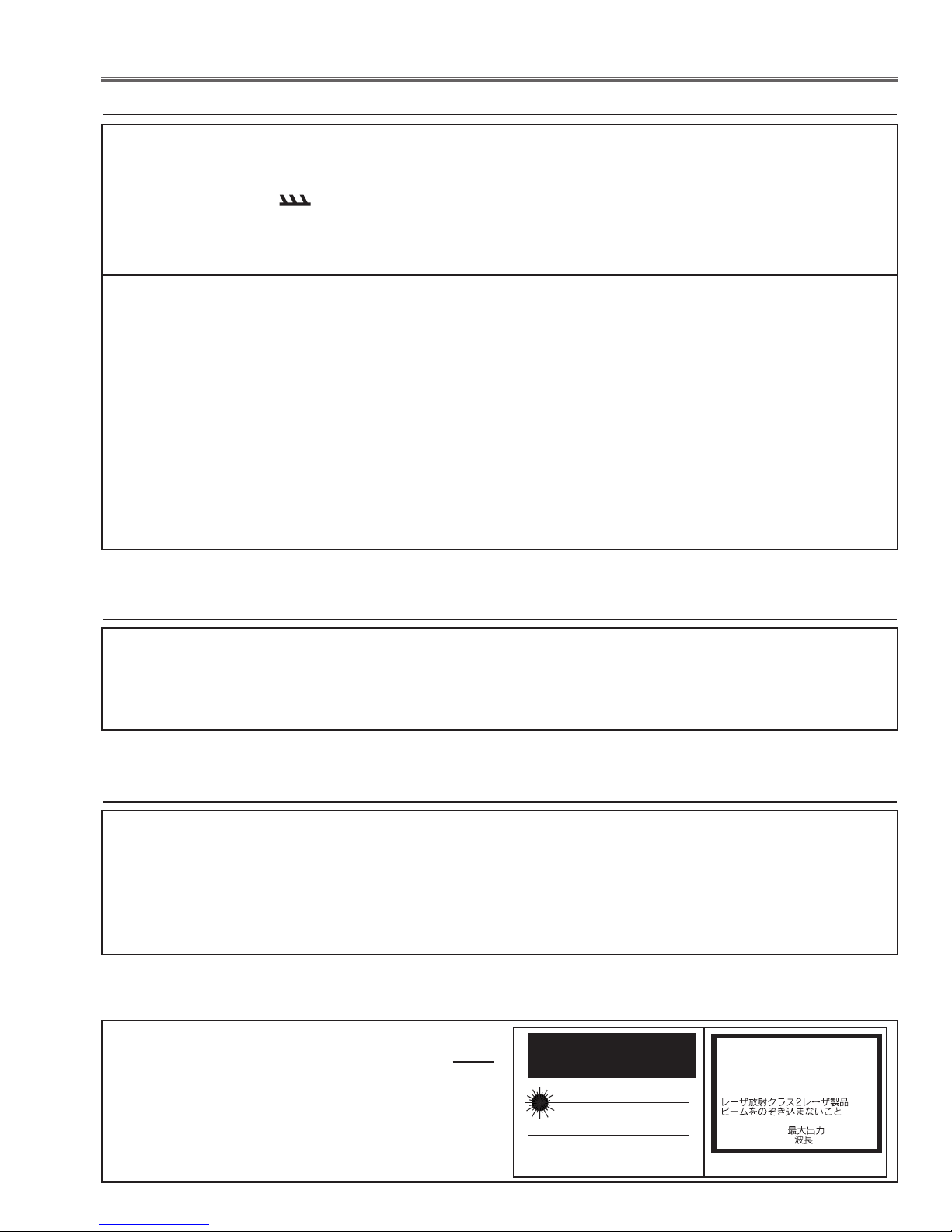
LASER RADIATION
DO NOT STARE INTO BEAM
MAX. OUTPUT: 1mW
WAVE LENGTH: 650 ±20nm
CLASS IILASER PRODUCT
This product is complied with 21 CFR
part 1040.10
CAUTION
LASER RADIATION
DO NOT STARE INTO BEAM
CLASS 2 LASER PRODUCT
LASER-STRAHLING
NICHT IN DEN STRAHL BLICKEN
LASER KLASSE 2
IEC60825-1, Am. 1 1997
MAX OUTPUT ( ) : 1 mW
WAVE LENGTH ( ) : 650±20nm
Safety Precautions
WARNING:
The chassis of this projector is isolated (COLD) from AC line by using the converter transformer. Primary side
of the converter and lamp power supply unit circuit is connected to the AC line and it is hot, which hot circuit is
identified with the line ( ) in the schematic diagram. For continued product safety and protection of personnel injury, servicing should be made with qualified personnel.
The following precautions must be observed.
ment covers or shields, barriers, etc.
1: An isolation transformer should be connected in
the power line between the projector and the AC
line before any service is performed on the projector.
DO NOT OPERATE THIS PROJECTOR WITHOUT
THE PROTECTIVE SHIELD IN POSITION AND PR
OPERLY SECURED.
2: Comply with all caution and safety-related notes
provided on the cabinet back, cabinet bottom, inside
the cabinet or on the chassis.
3: When replacing a chassis in the cabinet, always
be certain that all the protective devices are
installed properly, such as, control knobs, adjust-
4: Before replacing the cabinet cover, thoroughly
inspect the inside of the cabinet to see that no stray
parts or tools have been left inside.
Before returning any projector to the customer, the
service personnel must be sure it is completely safe
to operate without danger of electric shock.
Product Safety Notice
Product safety should be considered when a component replacement is made in any area of the projector.
Components indicated by mark ! in the parts list and the schematic diagram designate components in which
safety can be of special significance. It is, therefore, particularly recommended that the replacement of there
parts must be made by exactly the same parts.
Service Personnel Warning
Eye damage may result from directly viewing the light produced by the Lamp used in this equipment. Always
turn off Lamp before opening cover. The Ultraviolet radiation eye protection required during this servicing.
Never turn the power on without the lamp to avoid electric-shock or damage of the devices since the stabilizer
generates high voltages (15kV - 25kV) at its starts.
Since the lamp is very high temperature during units operation replacement of the lamp should be done at least
45 minutes after the power has been turned off, to allow the lamp cool-off.
DO NOT ATTEMPT TO SERVICING THE REM
OTE CONTROL UNIT.
Laser Beam may be leaked out when in disassemble
the Unit. As the Laser Beam used in this Remote control unit is harmful to the eyes.
-3-

Specifications
Mechanical Information
Projector Type Multi-media Projector
Dimensions (W x H x D) 13.7” x 6.46” x.17.48” (348.1 mm x 164 mm x 444 mm) (Not including adjustable feet)
Net Weight 5.7 lbs (2.6 kg)
Feet Adjustment 0˚ to 5.0˚
Panel Resolution
LCD Panel System 1.0” TFT Active Matrix type, 3 panels
Panel Resolution 1,024 x 768 dots
Number of Pixels 2,359,296 (1,024 x 768 x 3 panels)
Signal Compatibility
Color System
High Definition TV Signal 480i, 480p, 575i, 575p, 720p, 1035i, and 1080i
Scanning Frequency H-sync. 15 kHz–100 kHz, V-sync. 50 Hz–100 Hz
Optical Information
Projection Image Size (Diagonal) Adjustable from 30” to 300” (PLC-XT25/PLC-XT20)
Throw Distance 3.9’–32.8’ (1.2 m–10.0 m)
Projection Lens F=1.7 to 2.1, f=33 to 43 mm with manual zoom and focus
Projection Lamp 300 W
Interface
Input 1 Digital (DVI-D) x 1, Analog (Mini D-sub 15 pin) x 1
Input 2 BNC Type x 5 (G or Video/Y, B or Cb-Pb, R or Cr-Pr, HV and V)
Input 3 RCA Type x 1, Mini DIN 4 pin x 1
AUDIO IN Audio 1 (Mini Type stereo), Audio 2 (Mini Type stereo), Audio 3 (RCA Type) x 2
Analog Out
Audio Out
R/C Jack Mini Type (Wired Remote) x 1
Control Port Mini DIN 8 pin x 1
USB Connector USB Series B x 1
Option PJ-Net Organizer Terminal x 1
Mini D-sub 15 pin x 1
Audio (Mini Type stereo) x 1
Audio
Internal Audio Amp 1.0 W RMS
Built-in Speaker 1 speaker, ø1.0” (25 mm)
Power
Voltage and Power Consumption AC 100–120 V (4.6A Max. Ampere), 50/60 Hz (The U.S.A and Canada)
AC 200–240 V (2.3A Max. Ampere), 50/60 Hz (Continental Europe and The U.K.)
Operating Environment
Operating Temperature 41˚F–95˚F (5˚C–35˚C)
Storage Temperature 14˚F–140˚F (-10˚C–60˚C)
Remote Control
Battery AAA or LR03 Type x 2
Operating Range 16.4’ (5 m/±30˚)
Dimensions 1.8” (W) x 1.0” (H) x 5.7” (D) (45 mm x 25 mm x 145 mm)
Net Weight 3.5 oz (99 g) (including batteries)
Laser Pointer
PAL, SECAM, NTSC, NTSC4.43, PAL-M, and PAL-N
II
Class
Laser (Max. Output: 1 m W/Wave length: 640–660 mm)
This symbol on the nameplate means the product is Listed by Underwriters
Laboratories Inc. It is designed and manufactured to meet rigid U.L. safety standards against risk of fire, casualty and electrical hazards.
-4-
Circuit Protections
This projector provides the following circuit protections to operate in safety. If the abnormality occurs inside the projector, it will automatically turn off by operating one of the following protection circuits.
Fuse
A fuse is located inside of the projector. When the POWER
indicator is not lightning, the fuse may be opened. Check
the fuse as following steps.
The fuse should be used with the following type;
Fuse Part No. : 645 090 3144
TYPE T10.0AH 250V FUSE
SKY-GATE : TYPE SG5013010
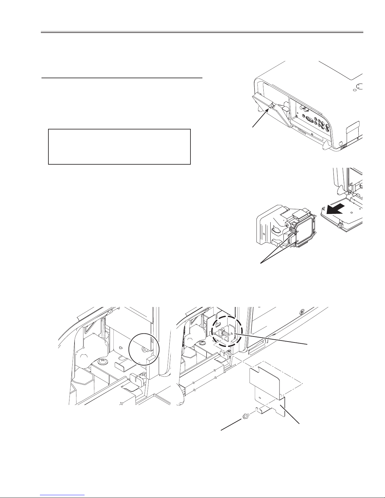
How to replace the fuse
1. Loosen the screw of the lamp cover and open the lamp
cover.
2. Loosen 2 screws of lamp ass'y and pull out the lamp
ass'y.
3. Remove the screw-A and remove the filter board cover
following to "Mechanical Disassemblies".
4. Remove the fuse from fuse holder on the Power(Filter)
board .
To install the fuse, take reversed step in the above.
cvx
Loosen the screw and
open the lamp cover.
Loosen the 2 screws and pull out
the lamp ass'y.
Screw-A
-5-
Fuse
Filter board
cover
Circuit Protections
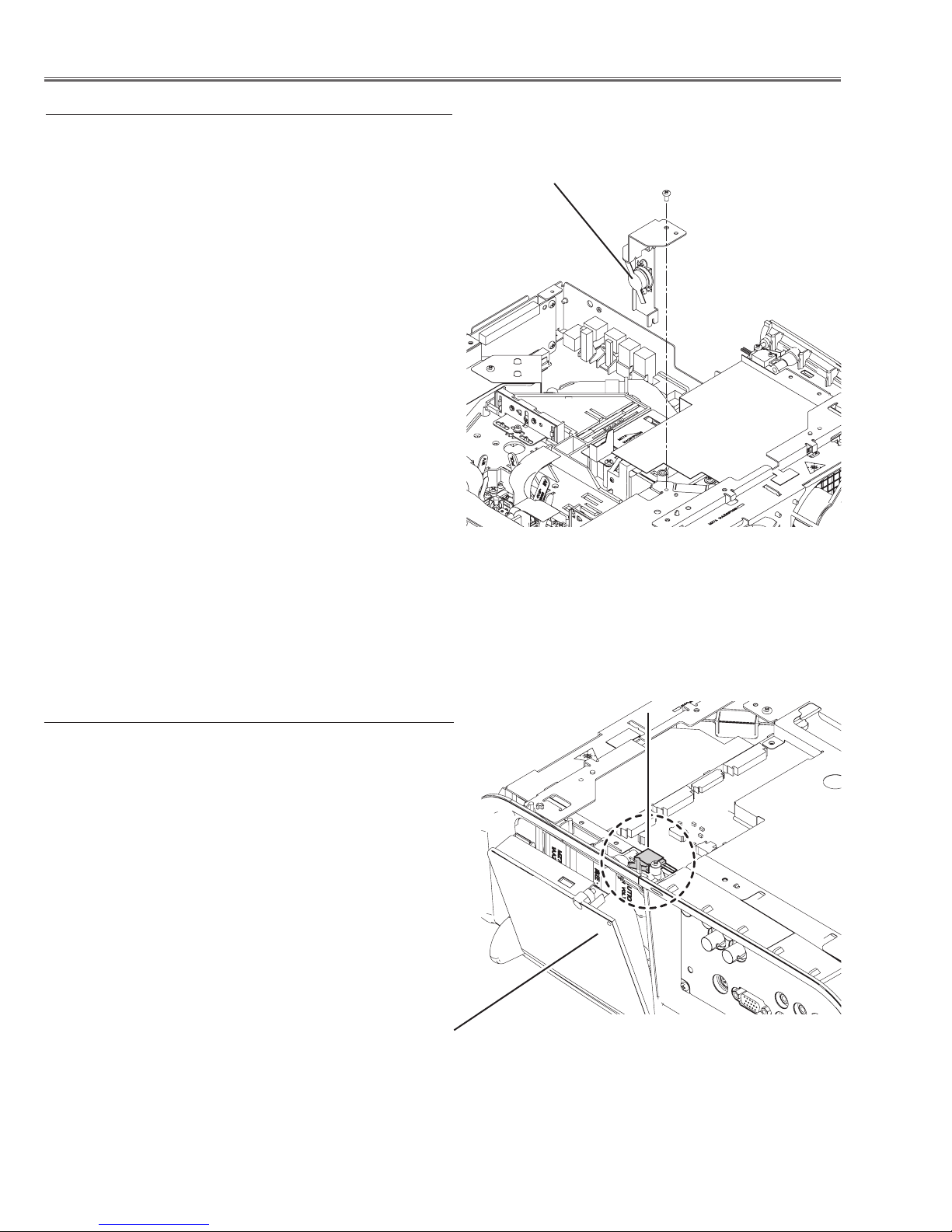
Thermostat (SW901)
There is the thermostat (SW901) inside of the projector to
detect the internal temperature rising abnormally. When the
internal temperature reaches near 100˚C, the thermostat
opens to stop the operation of the power supply circuit.
The thermostat will automaticallly return to normal condition when the internal temperature becomes normal (about
60
˚C)
.
Thermostat
(SW901)
Lamp cover switch (SW902)
The lamp cover switch (SW902) cuts off the drive signal
to the lamp circuit when the lamp cover is removed or not
closed completely. After opening the lamp cover for replacing the lamp ass’y, place the lamp cover correctly otherwise
the projector can not turn on.
Lamp cover
Lamp cover switch
(SW902)
-6-
Circuit Protections
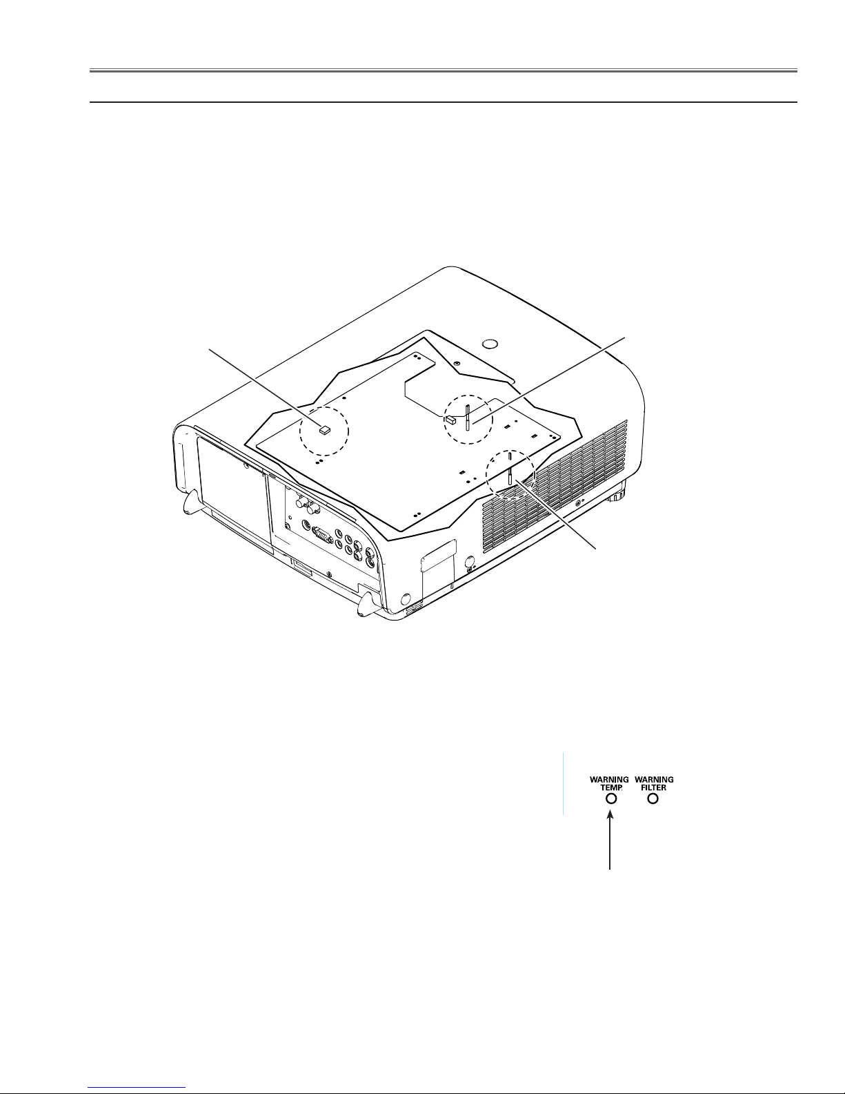
Temperature sensors (TH901, TH902, IC8841)
The projector provides a temperature sensor IC on the Main board and 2 thermistors. The temperature sensor IC
moniors arround the lamp house, the thermisstors are placed on the blue panel holder and on the intake duct.
- Internal temperature sensor A (IC8841) (arround the lamp house)
- Panel sensor B (TH902) (arround the blue panel)
- Room temperature sensor C (TH901) (arround the intake duct)
IC8841
(Behind PWB)
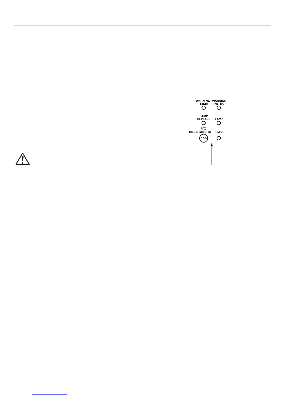
The projector is shut down and the WARNING TEMP. indicator is blinking red.
TH902
TH901
Top Control
When the temperature inside the projector reaches a certain
level, the projector will be automatically shut down to protect
the inside of the projector. The POWER indicator is blinking
while the projector is being cooled down. When the projector
has cooled down enough (to its normal operating temperature), it can be turned on again by pressing the ON/STANDBY button.
✔Note:
• The WARNING TEMP. indicator continues to blink even after
the temperature inside the projector returns to normal. When
the projector is turned on again, the WARNING TEMP. indica
tor stops blinking.
WARNING TEMP.
blinking red
-
-7-
Circuit Protections
Power failure and fan lock detection
The projector provides the detection circuits of the power failure and the fan lock. When the detection circuit detects
an error at the power supply line or at the fan operation circuit, the projector will turn into the standby mode to protect
the other circuits dfective.
The projector is shut down and all five indicators are
blinking.
When the projector detects an abnormal condition, it will be
automatically shut down to protect the inside of the projector and all five indicators on the top panel blink. In this case,
unplug the AC power cord and plug it, and then turn on the
projector once again to verify operation. If the projector cannot be turned on and these indicators are still blinking, unplug
the AC power cord.
CAUTION
DO NOT LEAVE THE PROJECTOR WITH THE AC
POWER CORD CONNECTED UNDER AN ABNORMAL CONDITION. IT MAY RESULT IN FIRE
OR ELECTRIC SHOCK.
Top Control
All five indicators
are blinking
-8-
Maintenance
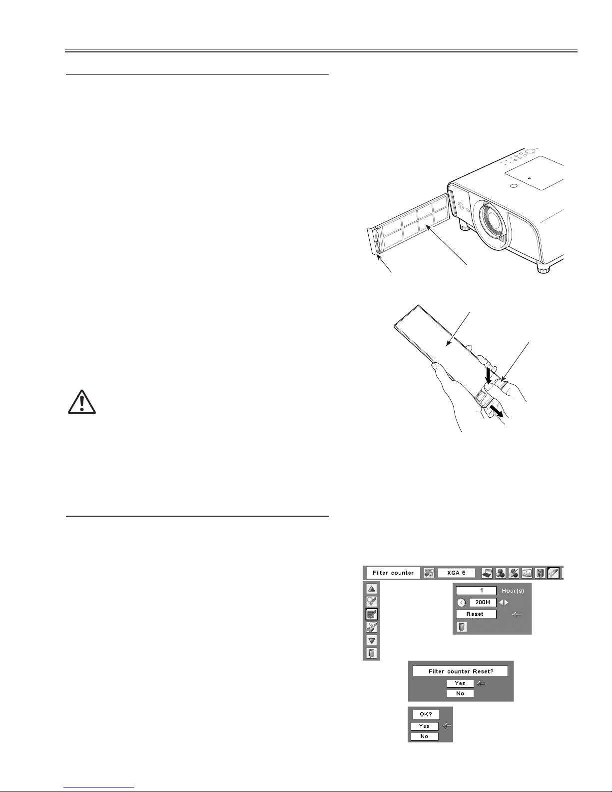
Cleaning the Air Filter
Filter prevents dust from accumulating on the optical elements inside the projector. Should the filter becomes
clogged with dust particles, it will reduce cooling fans’ effectiveness and may result in internal heat buildup and adversely affect the life of the projector. If a “Filter warning” icon (yellow or red) appears on the screen and the WARNING FILTER indicator lights or blinks, clean the filter immediately. Clean the filter by following the steps below.
Turn off the projector, and unplug the AC power cord
1
from the AC outlet.
First, clean up the dust on the projector and around the
2
air vents.
Pull out the filter cover from the projector and then re-
3
move the filter.
Gently clean the filter by using a brush or blower.
4
WARNING: Do not wash the filter with water and any
other liquid matter. Otherwise the filter may be damaged.
Reinstall the filter into the projector properly.
5
Filter cover
Filter
Filter
Filter cover
Reset the filter counter in the Setting Menu. See “Reset-
6
ting the Filter Counter” below.
CAUTION
Do not operate the projector with the filter removed.
Dust may accumulate on the optical elements degrading picture quality.
Do not put anything into the air vents. Doing so may
result in malfunction of the projector.
Press and hold the
filter cover and pull
out the filter.
NOTE: If the filter is heavily clogged and unable
Replacement Filter Part No.: 910-330-7184
Resetting the Filter Counter
Be sure to reset the Filter counter after cleaning or replacing the filter.
Press the MENU button to display the On-Screen Menu.
1
Use the Point 7 8 buttons to move the red framed
pointer to the Setting Menu icon.
Use the Point ed buttons to move the red framed point-
2
er to Filter counter and then press the SELECT button.
A dialog box appears showing the total accumulated
time of the filter use, a timer setting option, and the reset option. Select Reset and the “Filter counter Reset?”
appears. Select [Yes] to continue.
Another confirmation dialog box appears, select [Yes] to
3
reset the Filter counter.
Filter counter
to clean, replace it with a new one.
Consult your dealer for details.
Select Reset and the “ Filter
counter Reset?” appears.
Select [Yes],
then another
confirmation
box appears.
Select [Yes] again to reset
the Filter counter.
-9-
Maintenance
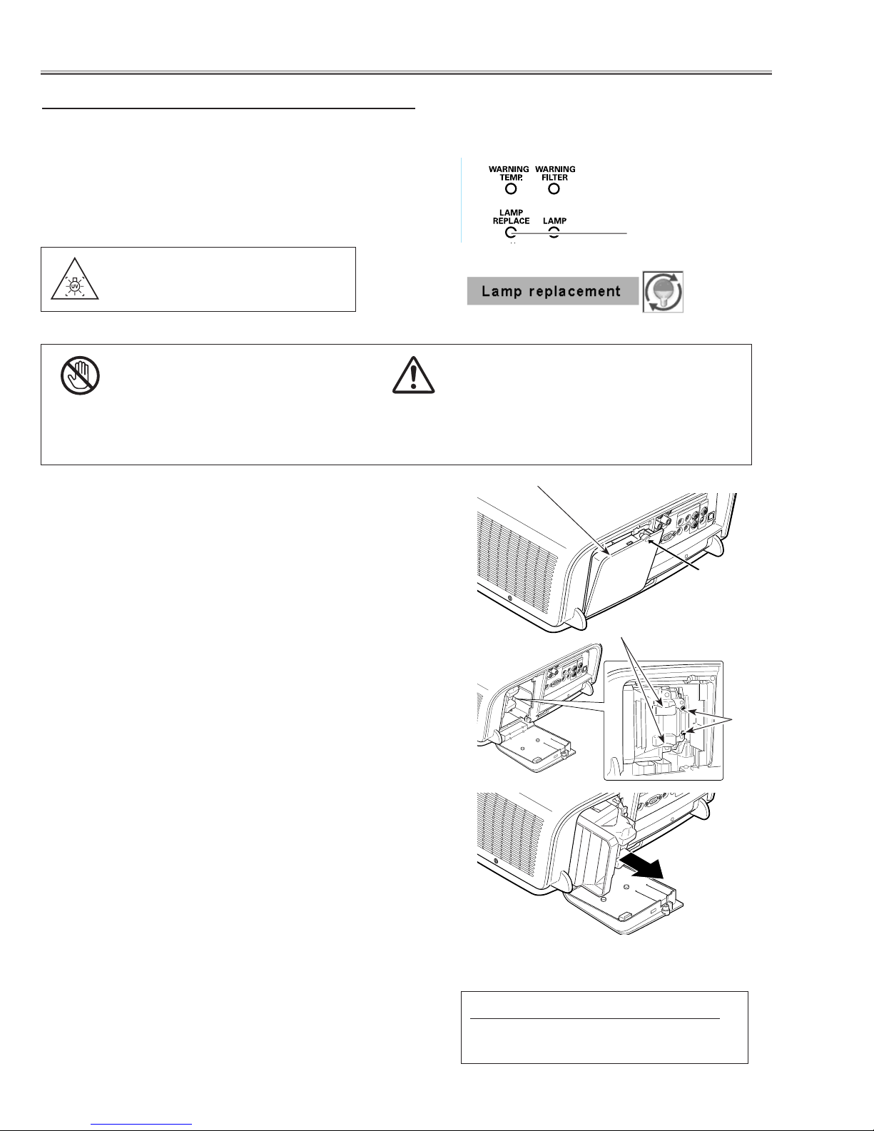
Lamp Replacement
When the projection lamp of the projector reaches its end
of life, the Lamp replacement icon appears on the screen
and LAMP REPLACE indicator lights yellow. Replace the
lamp with a new one promptly. The timing when the LAMP
REPLACE indicator should light is depending on the lamp
mode.
WARNING:
TURN OFF THE UV LAMP BEFORE
OPENING THE LAMP COVER
CAUTION
Allow a projector to cool for at least 45 minutes
before you open the Lamp cover. The inside of the
projector can become very hot.
Follow these steps to replace the lamp.
Turn off the projector and unplug the AC power cord. Let
1
the projector cool for at least 45 minutes.
For continued safety, replace with a lamp of the same
type lamp. Do not drop the lamp or touch the glass bulb!
The glass can shatter and may cause injury.
Top Control
LAMP REPLACE
indicator
Lamp replacement icon
CAUTION
Lamp Cover
Remove the screw that secures the lamp cover, and
2
then open the lamp cover.
Remove the two (2) screws that secure the lamp. Lift the
3
lamp out of the projector by using the handle.
Replace the lamp with a new one and secure the two (2)
4
screws. Make sure that the lamp is set properly. Put the
lamp cover back and secure it with the screw.
Connect the AC power cord to the projector and turn on
5
the projector.
Reset the lamp counter.
6
See “Resetting the Lamp Counter” on the next page.
Screw
Handle
Screws
ORDER REPLACEMENT LAMP
Type No. POA-LMP105
Service Parts No. 610 330 7329
-10-
Counter
Projector 750 H
Lamp
High 200 H
Normal 250 H
Eco 300 H
Corresponding value 900 H
Maintenance
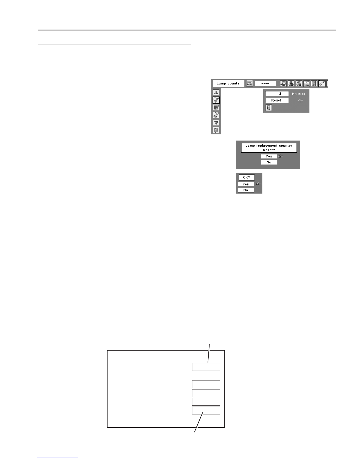
Resetting the Lamp Counter
Be sure to reset the Lamp counter after the lamp is replaced. When the Lamp counter is reset, the LAMP REPLACE indicator stops lighting and the Lamp replacement icon disappears.
Press the MENU button to display the On-Screen Menu.
1
Use the Point 7 8 buttons to move the red framed
pointer to the Setting Menu icon.
Use the Point ed buttons to move the red framed point-
2
er to Lamp counter and then press the SELECT button.
A dialog box appears showing the total accumulated time
of the lamp usage and the reset option. Select Reset and
the “Lamp replacement counter Reset?” appears. Select
[Yes] to continue.
Another confirmation dialog box appears, select [Yes] to
3
reset the Lamp counter.
✔Note:
• Do not reset the Lamp counter without implementing lamp
replacement. Be sure to reset the Lamp counter only after
replacing the lamp.
Lamp counter
Select Reset and the “Lamp
replacement counter Reset?”
appears.
Select [Yes],
then another
confirmation
box appears.
Select [Yes] again to reset
the Lamp counter.
How to check Lamp Used Time
The LAMP REPLACE indicator will light yellow when the total lamp used time (Corresponding value) reaches 3,000
hours. This is to indicate that lamp replacement is required.
The total lamp used time is calculated by using the below expression,
Total lamp used time (Corresponding value) = Teco + (Tnormal x 1.2) + (Thigh x 1.5)
Teco: used time in the Eco mode
Tnormal : used time in the Normal mode
Thigh : used time in the High mode
You can check the lamp used time following to the below procedure.
1 Press and hold the ON/STAND-BY button on the projector for more than 20 seconds.
2 The projector used time and lamp used time will be displayed on the screen briefly as follows.
Projector used time
Total lamp used time
-11-
Maintenance
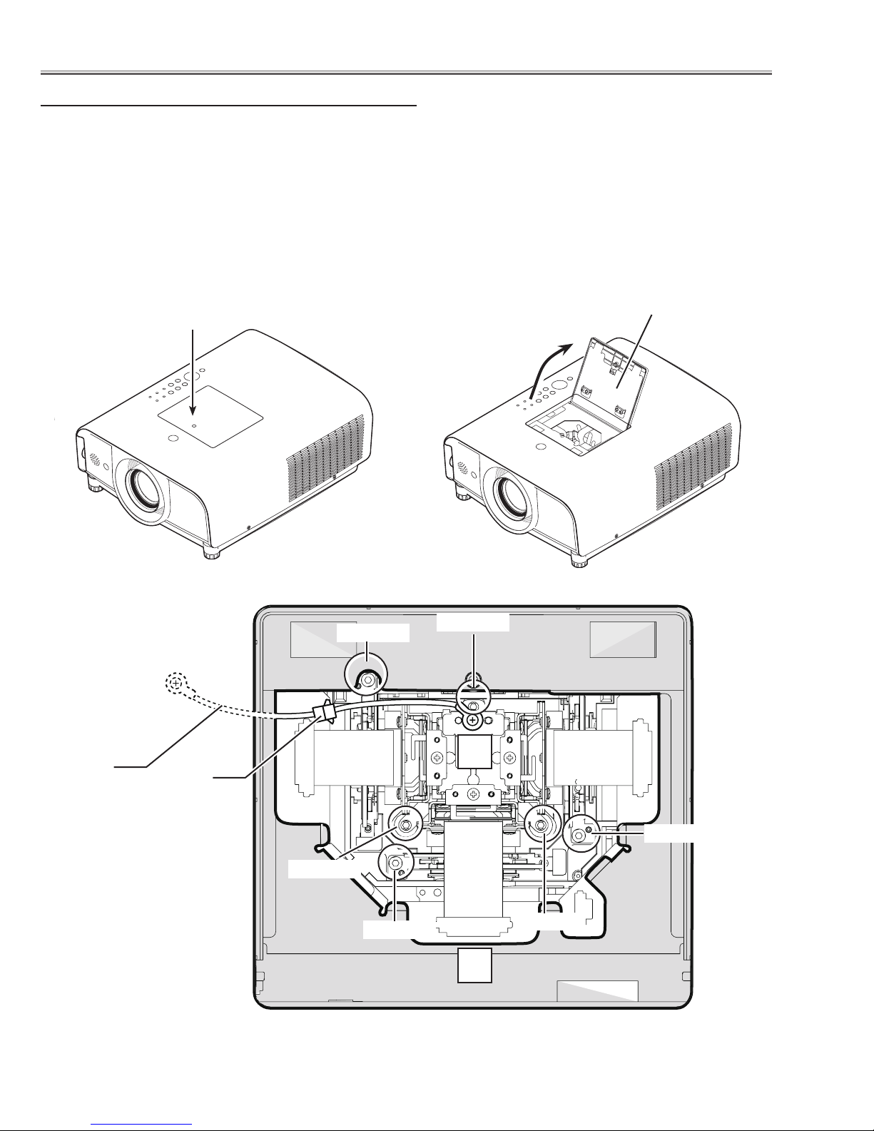
Quick maintenance
This projector provides a prism cover on the cabinet top to enhance the service maintenance. This enables service
personel to align the optical adjustment or replace the optical parts without disassembly the cabinet top.
1. Loosen 1 screw-A and open the prism cover panel.
2. To remove the LCD Panel/Prism ass'y, loosen 3 screws-B and disonnect a socket-D, and then pull the LCD Panel/
Prism ass'y up.
3. To remove the Optical filter ass'y, remove a screw-C on each stopper of the Optical filter ass'y and then pull the
Optical filter ass'y up.
Prism cover panel
Screw-A
Maintenance
Grounding
wire
Socket-D
Screw-B
Screw-C
Screw-C
Screw-B
L
Screw-C
Screw-B
L
-12-
Maintenance
!
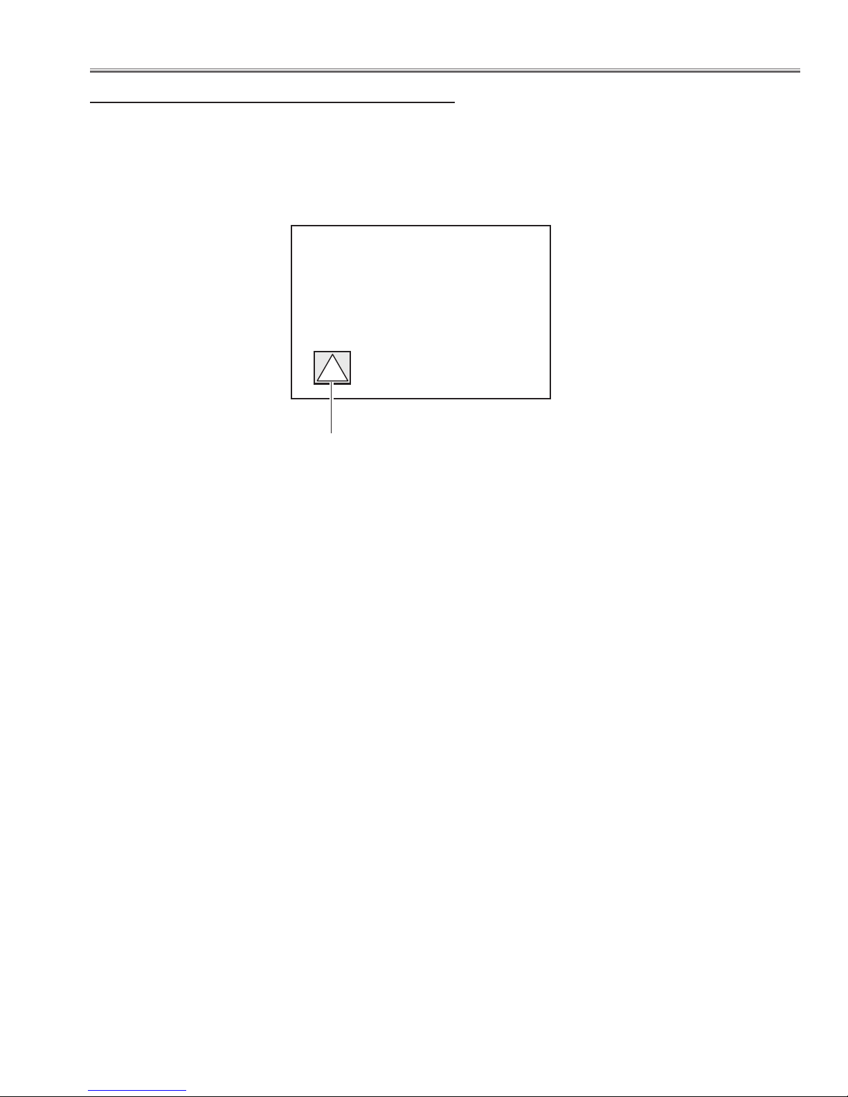
Prohibotion of motor control
This projector provides a function to prohibit the operation of motors. After installing the projector and then setting up
this function. You can protect the unexpected operation by the users. All the motor controls, Focus, Zoom and Lensshift, will not be operated. The prohibition icon will appear on the screen when user presses any of the motor control
buttons.
Prohibition icon
Setting up procedures
1. Enter the service mode.
2. Select Group no. "200" and Item no. "50". Change Data value from "0" (Not prohibited) to "1" (Prohibited). Now the
motor control is prohibited.
3. Exit from the service mode.
To cancel the prohibition mode, set value to "0" in the step 2.
* How to enter the service mode and select the group, item and data value, see "Service Adjustment Menu Opera-
tion".
-13-
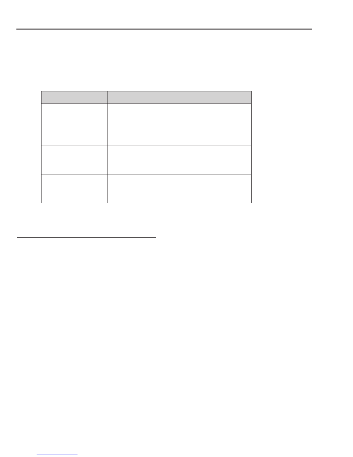
Security Function Notice
This projector provides security functions such as "Key lock", "PIN code lock" and "Logo PIN code lock". When the projector has set these security function on, you are required to enter correct PIN code to use the projector. If you do not
know the correct PIN code to the projector, the projector can no longer be operated or started. In this case, you must
reset those function first according to the resetting procedure described below and then check up on the projector.
Function Description
Locks operation of the top control or the remote control.
Key lock
PIN code lock
Logo PIN code lock
If the Key lock is enabled with top control lock, the projector can no longer be started.
Initial setting: Key lock function is disabled
Prevents the projector from being operated by an unauthorized person.
Initial code: “1234”
Prevents an unauthorized person for changing the
start-up logo on the screen.
Initial code: “4321”
Resetting procedure
1 Disconnect the AC power cord from the AC outlet.
2 As pressing the SELECT button on the projector, connect the AC power cord into an AC outlet again. Keep
pressing the SELECT button until the POWER indicator lights continuously.
This is complete the resetting of the security function. The PIN code lock and Logo PIN code lock are reset
as the initial PIN code at the factory and the Key lock function is disabled.
Please refer to the owner's manual for further information of the security functions.
-14-
Mechanical Disassembly
Mechanical disassembly should be made following procedures in numerical
order.
Following steps show the basic procedures, therefore unnecessary step may
be ignored.
Caution:
The parts and screws should be placed exactly the same position as the original otherwise it may cause loss of performance and product safety.
The wiring method of the leads and ferrite cores should be returned exactly
the same state as the original, otherwise it may cause lose of performance and
product safety.
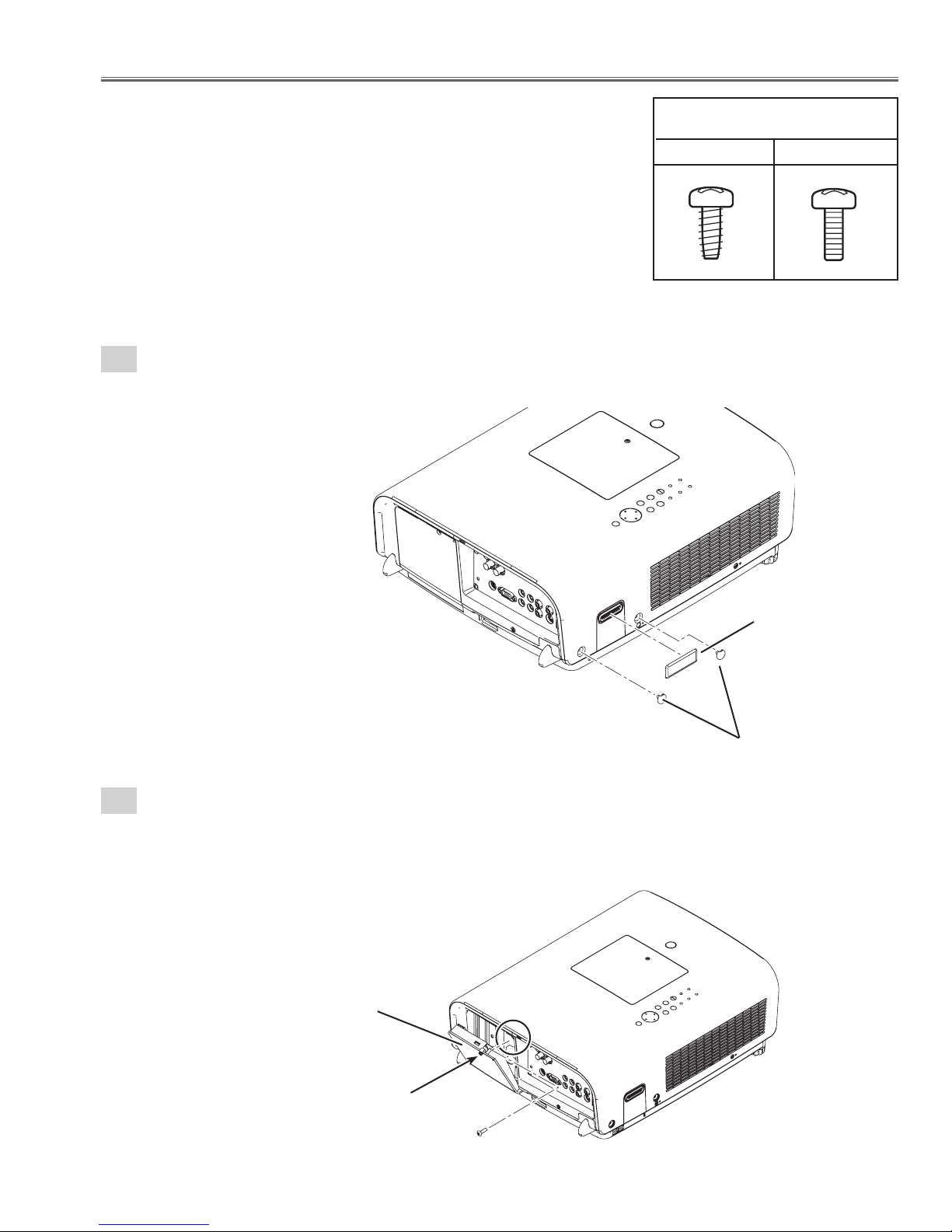
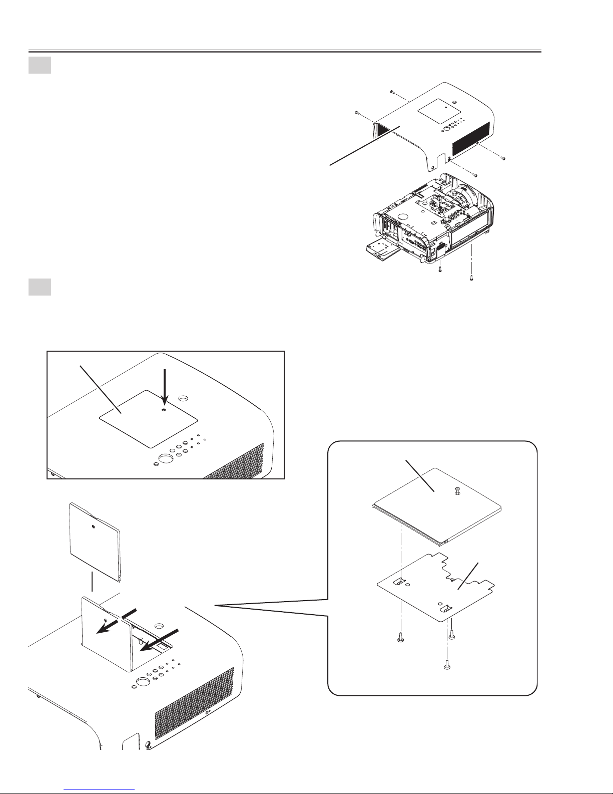
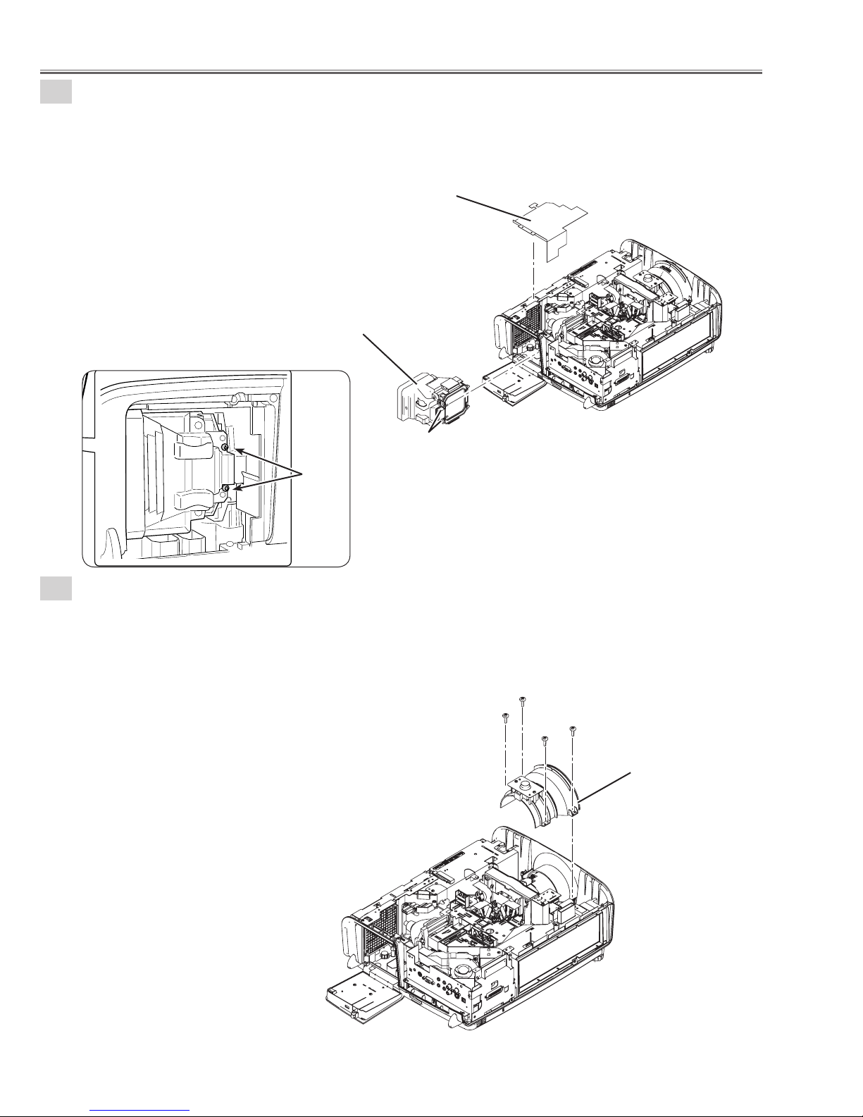
1-1
Cabinet top ass'y removal-1.
1. Remove 1 cover-A and 2 covers-B.
Screws Expression
(Type Diameter x Length) mm
T type M Type
Fig. 1-1
1-2
Cabinet top ass'y removal-2.
1. Loosen 1 screw-A(M3X11) and open the Lamp cover.
2.Remove 1 screw-B(M3X8).
Lamp cover
Cover-A
Cover-B
A
B
-15-
Fig. 1-2
Mechanical Disassembly
1-3
Cabinet top ass'y removal-3.
1. Remove 6 screws-A(M3X8) and remove the Cabinet top
ass'y.
A
A
Cabinet top ass'y
Fig. 1-3
1-4
Cabinet top ass'y removal-4.
1. Loosen screw-A(M3X11) and open the Prism cover panel.
(Press 2 places (unhook) and remove the Prism cover panel upward.)
2. Remove 3 screws-B(T3X8) and remove the shield plate.
Prism cover panel
A
A
A
A
A
Fig. 1-4a
Press the 2 places
(unhook) and upward
Fig. 1-4
Prism cover panel
B
B
Shield plate
B
-16-
Mechanical Disassembly
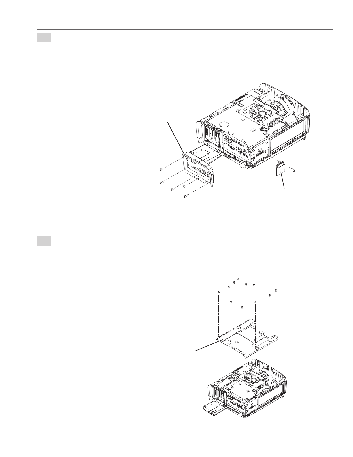
2
AV Panel and Side Panel removal.
1. Remove 5 screws-A(M3X8) and remove the AV Panel.
2. Remove 1 screw-B(M3X6) and remove the Side Panel.
AV panel
A
A
A
A
A
3
Shield plate top-A removal.
1. Remove 11 screws-A(M3X6) and remove the Shield plate top-A.
B
Side panel
Fig. 2
A
A
A
A
A
A
A
A
A
A
A
Shield plate top-A
Fig. 3
-17-
Mechanical Disassembly
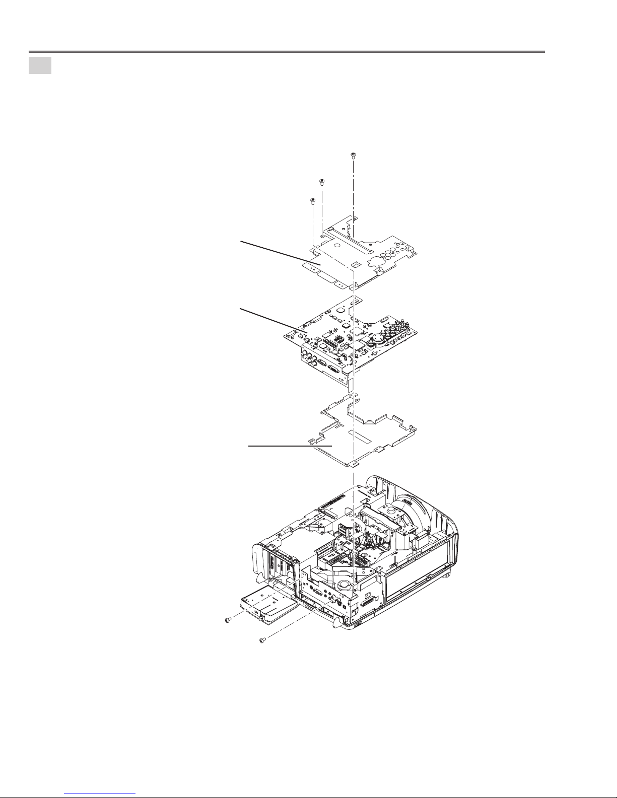
4-1
Main board ass'y removal-1.
1. Remove 3 screws-A(M3X6) and remove 2 screws-B(M3X6).
2.Remove the Shield plate top-B, Main board ass'y and remove the Shield plate bottom.
A
A
A
Shield plate top-B
Main board ass'y
Fig. 4-1
Shield plate bottom
B
B
-18-
Mechanical Disassembly
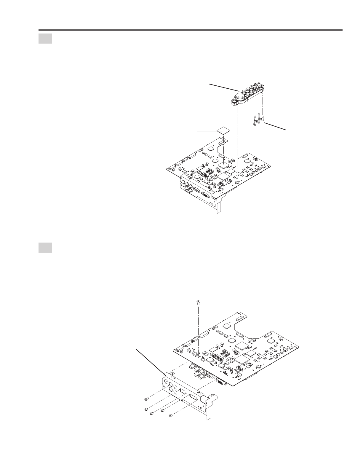
4-2
Main board ass'y removal-2.
1. Unhook and remove the Button upward.
2. Remove the DEC inlay.
3. Remove the Heat sink sheet-A.
Button
Heat sink sheet-A
4-3
Main board ass'y removal-3.
1. Remove 1 screw-A(M3X6).
2. Remove 2 nuts-B, 2 nuts-C, 1 screw-D and remove the Main PWB Holder.
A
DEC inlay
Fig. 4-2
Main PWB Holder
D
Fig. 4-3
C
B
C
B
-19-
Mechanical Disassembly
5
Lamp ass'y removal.
1. Loosen 2 screws-A(M3X13) and remove the Lamp ass'y.
2. Remove the Spacer sheet.
Lamp ass'y
Spacer sheet
Fig. 5
A
A
Lens cover ass'y removal-1.
6-1
1. Remove 4 screws-A(T3X8) and remove the Lens cover ass'y.
A
A
A
A
Lens cover ass'y
Fig. 6-1
-20-
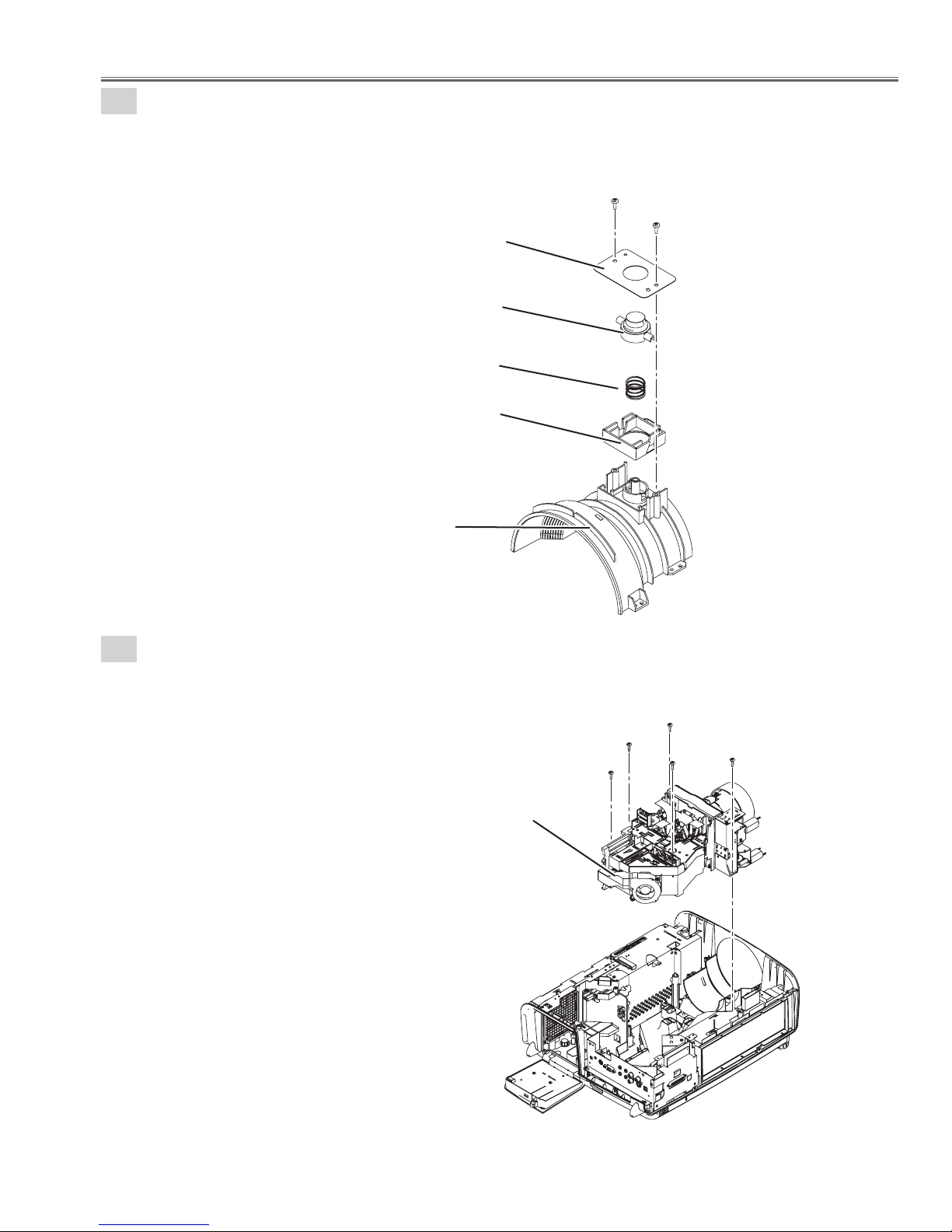
Mechanical Disassembly
6-2
Lens cover ass'y removal-2.
1. Remove 2 screws-A(T3X8) and remove the Stopper button.
2. Remove the Button, remove the Spring and remove the Holder.
A
Stopper button
Button
Spring
Holder
Lens cover top
7
Optical engine removal.
1. Remove 5 screws-A(T3X10) and remove the Optical engine.
A
Fig. 6-2
Optical engine
A
A
A
A
A
Fig. 7
-21-
Mechanical Disassembly
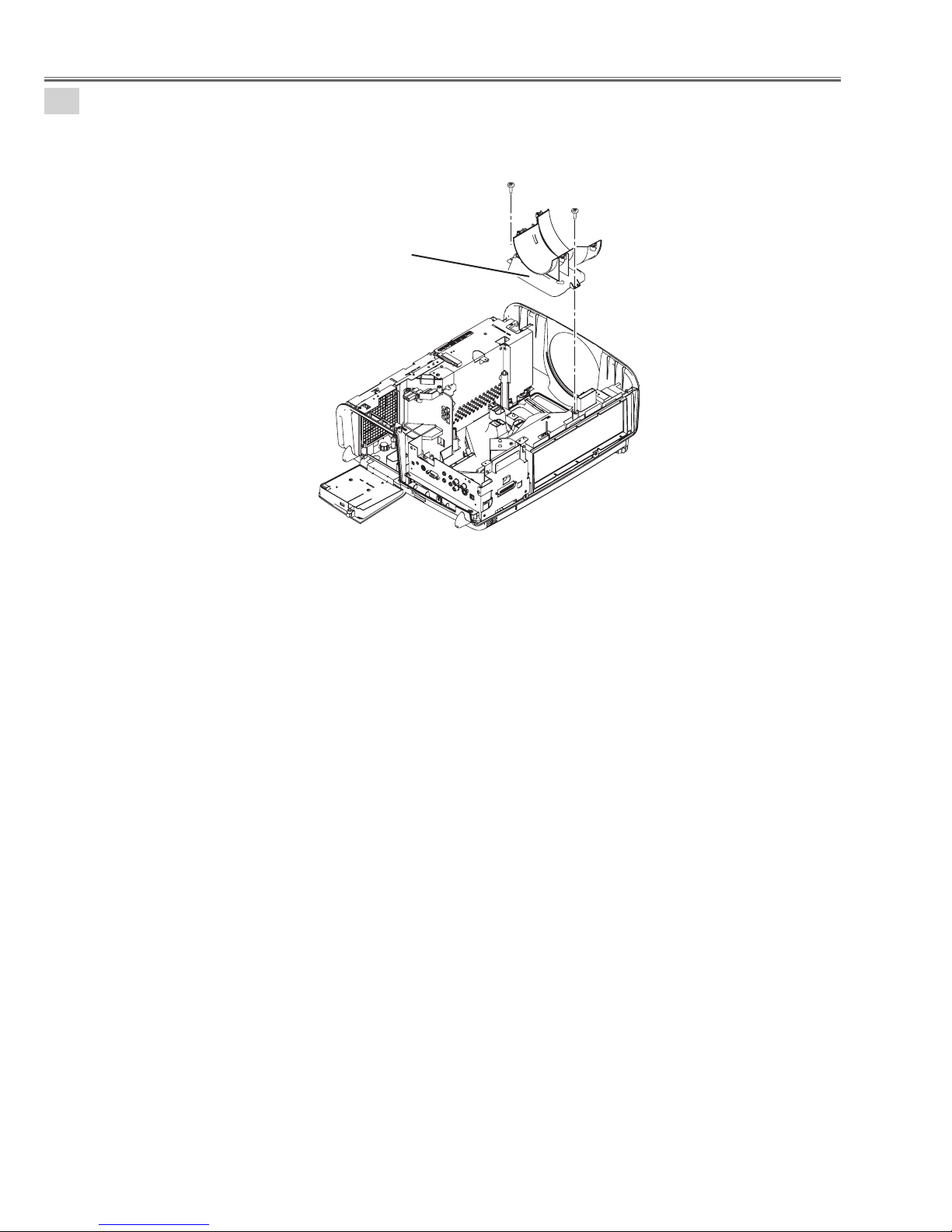
8
Lens cover bottom removal.
1. Remove 2 screws-A(T3X8) and remove the Optical engine.
Lens cover bottom
A
A
Fig. 8
-22-
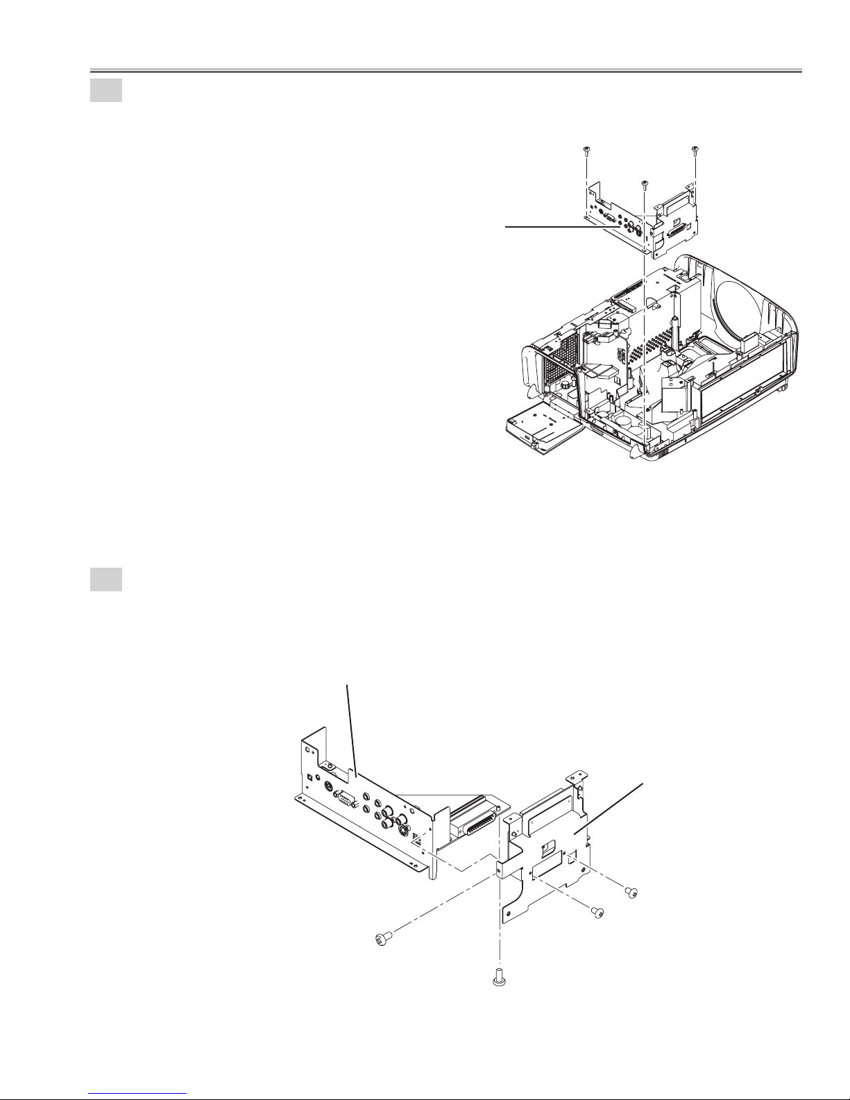
Mechanical Disassembly
9-1
AV board & Network joint board ass'y removal-1.
1. Remove 3 screws-A(T3X8) and remove the AV board & Netwark joint board ass'y.
AV board & Network joint board ass'y
A
A
A
Fig.9-1
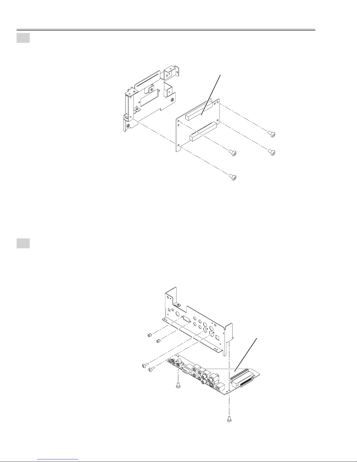
9-2
AV board & Network joint board ass'y removal-2.
1. Remove 2 screws-A(M3X6) and 2 screws-B(M2.6X10).
2. Remove the AV board ass'y and remove the Network joint board ass'y.
AV board ass'y
A
Network joint board ass'y
B
B
-23-
A
Fig.9-2
Mechanical Disassembly
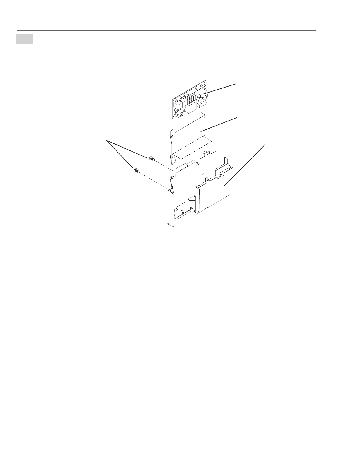
9-3
AV board & Network joint board ass'y removal-3.
1. Remove 4 screws-A(M3X6) and remove the Network joint board.
Network joint board
A
9-4
AV board & Network joint board ass'y removal-4.
1. Remove 2 screws-A(M3X6), 2 screws-B(T3X8) and remove 2 nuts-C.
2. Remove the AV board.
A
A
A
Fig.9-3
C
C
B
B
A
AV board
Fig.9-4
A
-24-
Mechanical Disassembly
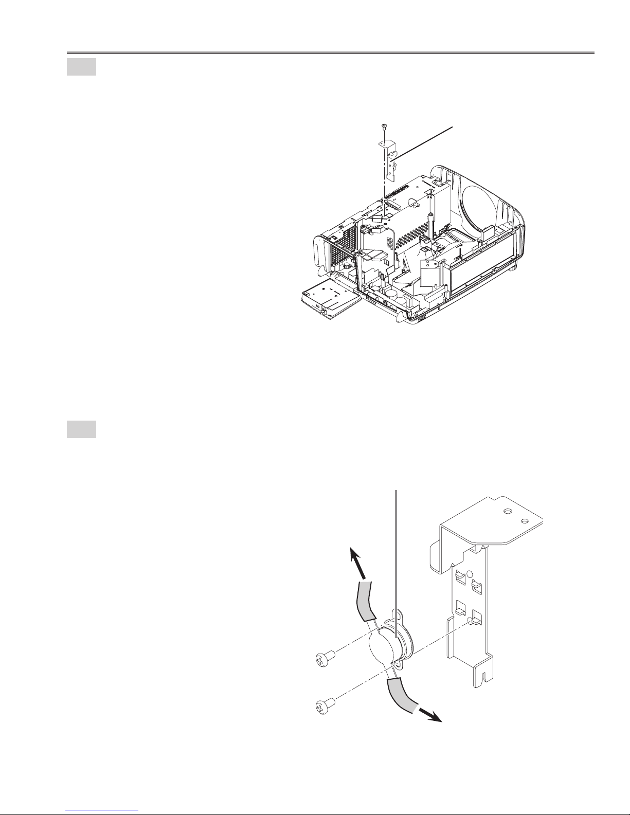
10-1
Thermostat(SW901) ass'y removal-1.
1. Remove 1 screw-A(M3X6) and remove the Thermostat(SW901) ass'y.
A
Thermostat ass'y
Fig.10-1
10-2
Thermostat(SW901) ass'y removal-2.
1. Remove 2 screws-A(M3X4) and remove the Thermal switch(SW901).
Thermostat(SW901)
To Power(DC) unit
A
Fig.10-2
A
To Power(filter unit)
-25-
Mechanical Disassembly
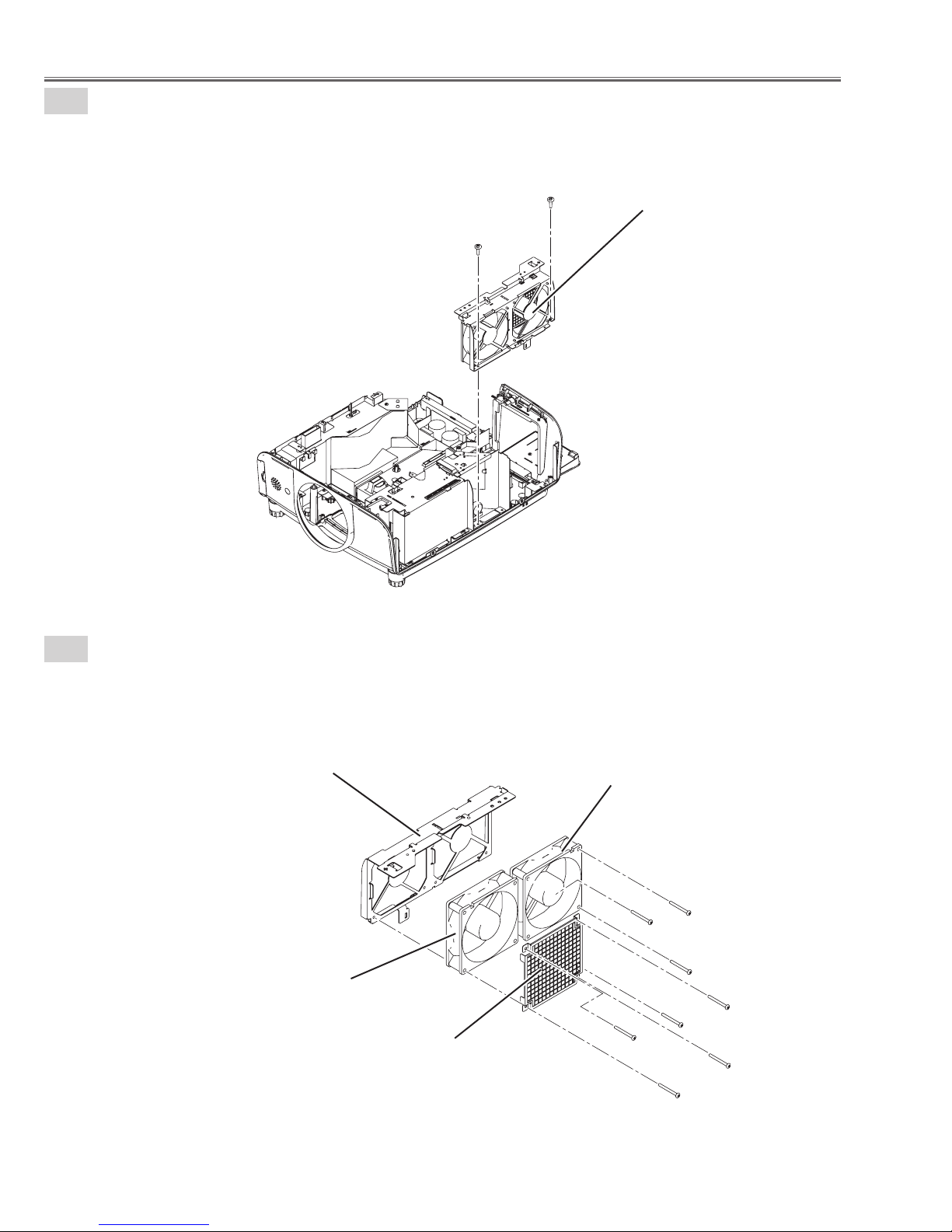
11-1
Exhaust Fan(FN901, FN902) ass'y removal-1.
1. Remove 2 screws-A(T3X8) and remove the Exhaust Fan(FN901, FN902) ass'y.
A
Exhaust Fan ass'y
A
Fig.11-1
11-2
Exhaust Fan(FN901, FN902) ass'y removal-2.
1. Remove 4 screws-A(M3X28), remove the Fan guard cover and the Fan(FN901).
2. Remove 4 screws-B(M3X28) and remove the Fan(FN902).
Holder Fan
Fan(FN901)
Fan guard cover
Fig.11-2
Fan(FN902)
B
B
B
A
B
A
A
A
-26-
Mechanical Disassembly
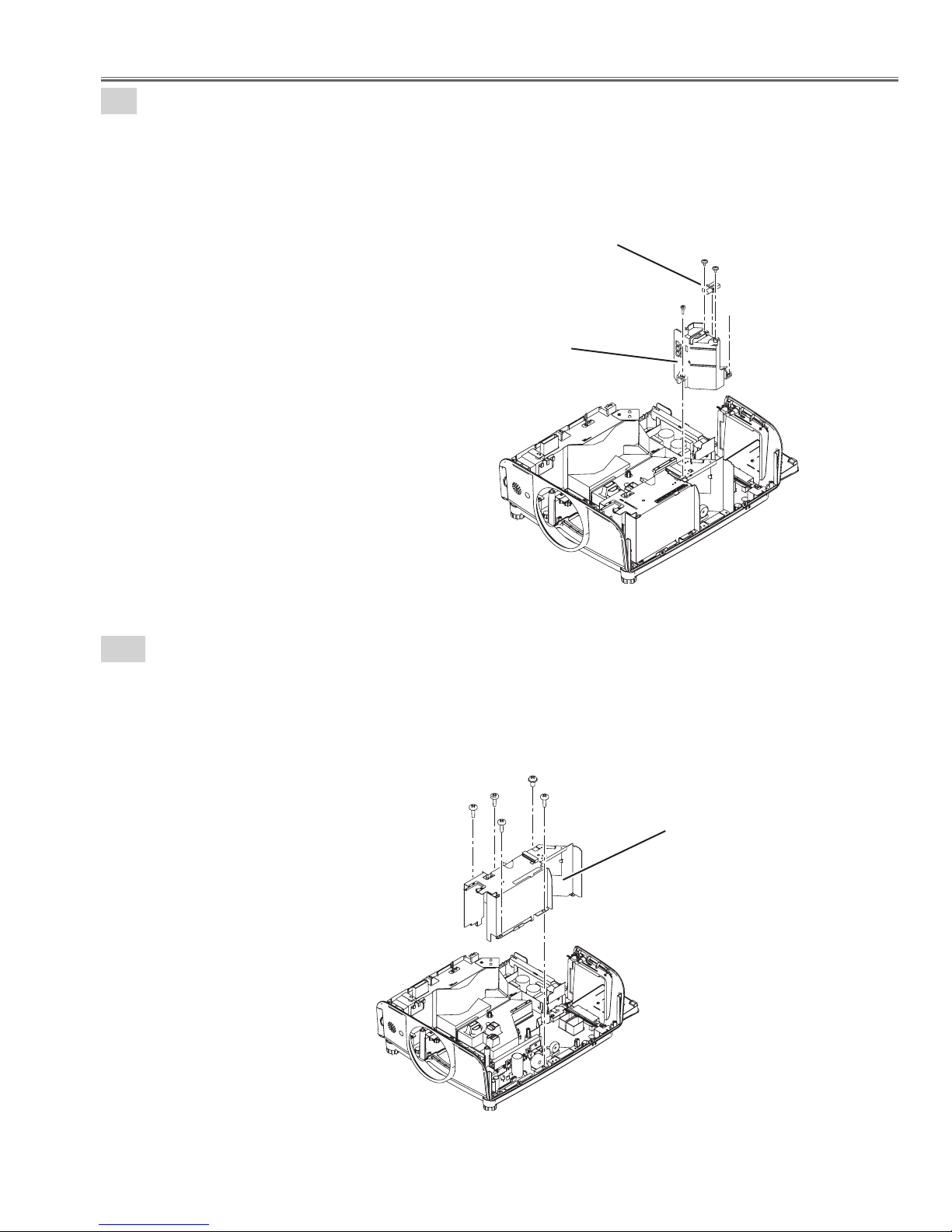
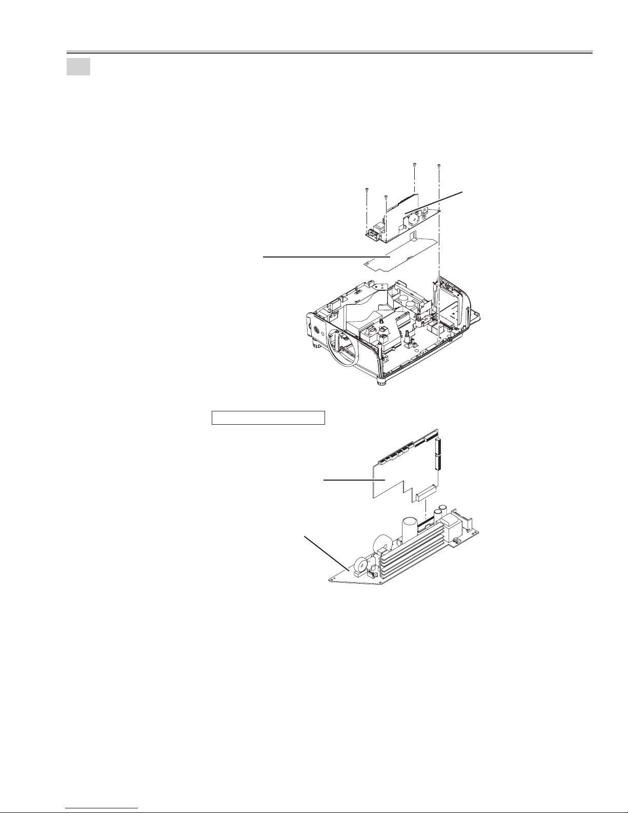
12
Exhaust Fan duct removal.
1. Remove 2 screws-A(T3X6) and remove the Lamp ballast connector.
2. Remove 2 screws-B(T3X10) and remove Exhaust Fan duct.
13-1
Lamp ballast connector
Exhaust Fan duct
Power board(Ballast) ass'y removal-1.
1. Remove 1 screw-A(M3X6), 4 screws-B(T3X8) and remove the Power board(Ballast) ass'y.
A
A
B
B
Fig.12
A
B
B
B
B
Power board(Ballast) ass'y
Fig.13-1
-27-
Mechanical Disassembly
13-2
Power board(Ballast) ass'y removal-2.
1. Remove 2 Fixer clamp and remove the Power board(Ballast).
2. Remove the Spacer sheet.
Ballast board
(A901)
Spacer sheet
Fixer clamp
Shield plate main power
Fig.13-2
-28-
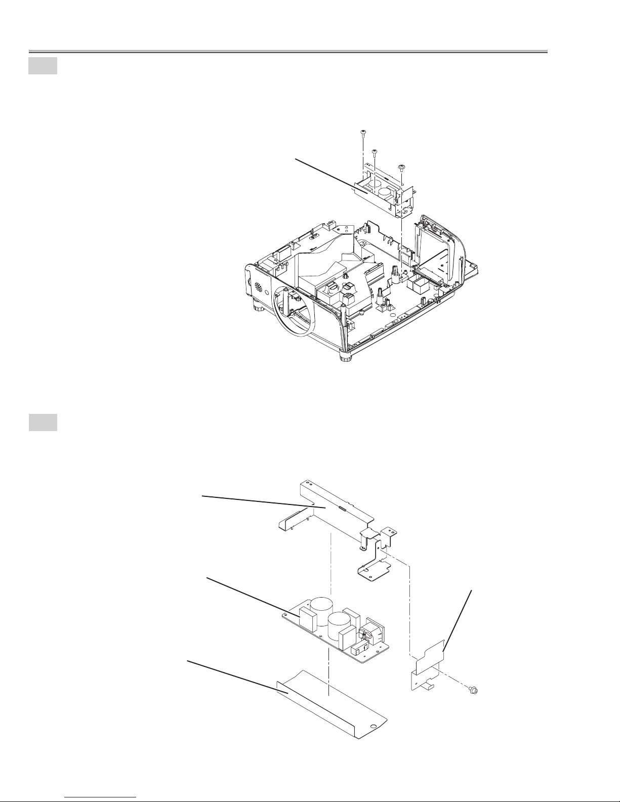
Mechanical Disassembly
14
Power board ass'y removal.
1. Remove 1 screw-A(M3X8), 3 screws-B(T3X8) and remove the Power board ass'y.
2. Remove the Spacer sheet.
A
B
B
Spacer sheet
B
Power board ass'y
Fig.14a
Power board ass'y
Power board(DC)
(A903)
Power board(AC)
(A902)
Fig.14b
-29-
Mechanical Disassembly
15-1
Power board(Filter) ass'y removal-1.
1. Remove 1 screw-A(M3X6), 2 screws-B(T3X8) and remove the Power board(Filter) ass'y.
B
B
Power board(Filter) ass'y
A
Fig.15-1
15-2
Power board(Filter) ass'y removal-2.
1. Remove 1 screw-A(M2.5X5) and remove the Fuse cover.
2. Remove the Holder PWB, remove the Spacer sheet and remove the Power board(Filter).
Holder PWB
Power board(Filter)
(A904)
Spacer sheet
Fuse cover
A
Fig.15-2
-30-
 Loading...