

SANYO PLC-XT10 Service Manual
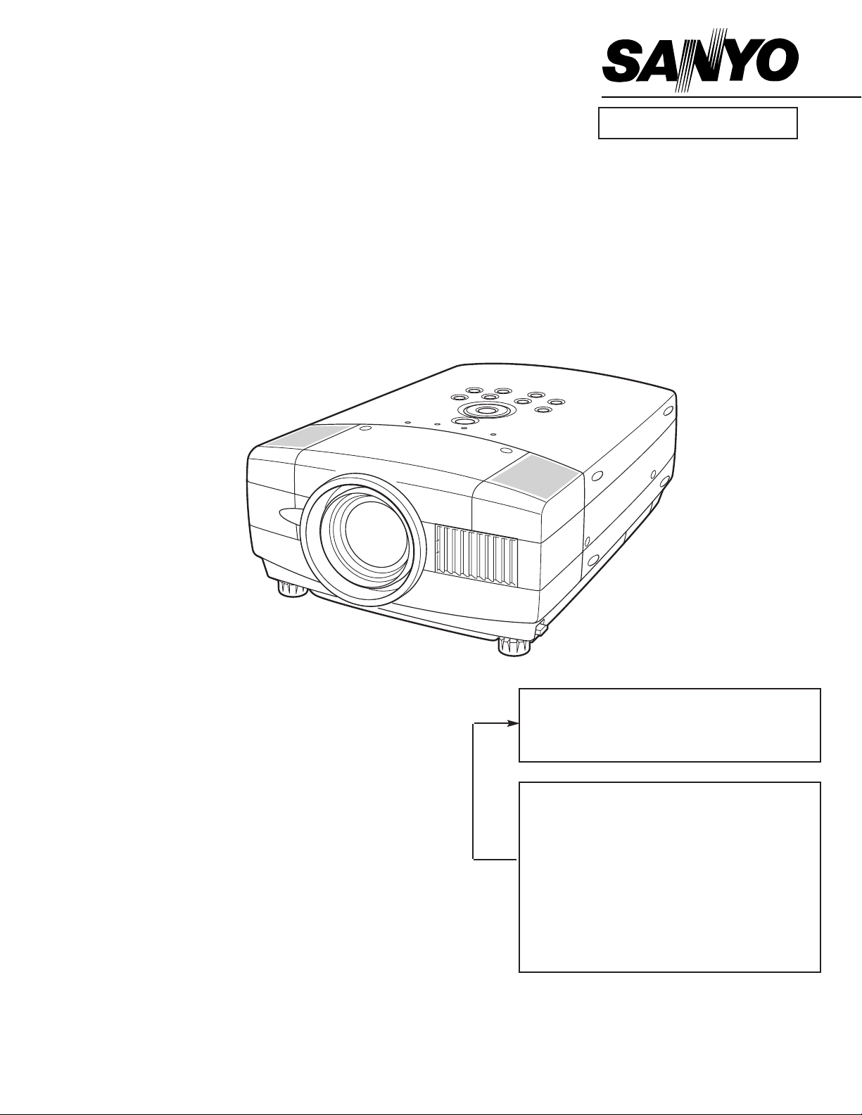
Multimedia Projector
SERVICE MANUAL
PRODUCT CODE
1 122 163 00
(MD3A)
1 122 164 00 (PD3A)
1 122 164 02 (PD3C)
Original Version
REFERENCE NO. SM5110412
FILE NO.
Model No. PLC-XT10
U.S.A., Canada,
Europe, Asia, Africa
Chassis No. MD3-XT1000
NOTE: Match the Chassis No. on the unit’s
back cover with the Chassis No. in the
Service Manual.
If the Original Version Service
Manual Chassis No. does not match
the unit’s, additional Service
Literature is required.You must refer to
“Notices” to the Original Service
Manual prior to servicing the unit.

-2-
■ Contents
■ Safety Instructions ________________________________________________3
■ Specifications____________________________________________________4
■ Adjustments after Parts Replacement ________________________________5
■ Circuit Protections ________________________________________________6
Fuse ______________________________________________________6
Thermal switch ______________________________________________6
Interlock switch ______________________________________________6
Warning temperature and power failure protection __________________7
■ Mechanical Disassemblies ________________________________________8
■ Optical Parts Disassemblies ______________________________________13
■ LCD Panel/Prism Ass’y Replacement ________________________________18
■ Lamp Replacement ______________________________________________19
■ Optical Adjustments______________________________________________20
■ Electrical Adjustments ____________________________________________24
Service Adjustment Menu Operation______________________________24
Circuit Adjustments __________________________________________25
Test Points and Locations ______________________________________30
Service Adjustment Data Table __________________________________31
Chassis over view ____________________________________________39
■ Chassis Block Diagrams __________________________________________39
Inputs & video signal processing stage ____________________________40
LCD panel driving stage ______________________________________41
Audio signal processing circuit __________________________________42
Motor driving circuit __________________________________________43
System controls ______________________________________________44
Power supply & protection circuit ________________________________45
■ Troubleshooting ________________________________________________46
No Power __________________________________________________46
No Picture __________________________________________________47
No Sound __________________________________________________48
Lens Motor Problems__________________________________________48
■ Control Port Functions ____________________________________________49
■ Waveform ______________________________________________________54
■ Cleaning ______________________________________________________56
■ IC Block Diagrams ______________________________________________57
■ Service Parts List ____________________________________________67-102
Electrical Parts List ________________________________________67-96
Mechanical Parts List ______________________________________97-102
Drawings & Diagrams
■ Parts description and reading in schematic diagram____________________ A2
■ Schematic diagrams ________________________________________ A3-A10
■ Printed wiring board diagrams ________________________________ A11-A15
■ Pins description of ICs, transistors, diodes __________________________ A16
-3-
■ Safety Instructions
WARNING:
The chassis of this projector is isolated (COLD) from AC line by using the converter transformer. Primary side of
the converter and lamp power supply unit circuit is connected to the AC line and it is hot, which hot circuit is identified with the line ( ) in the schematic diagram. For continued product safety and protection of personnel
injury, servicing should be made with qualified personnel.
The following precautions must be observed.
SAFETY PRECAUTIONS
1: An isolation transformer should be connected in the
power line between the projector and the AC line
before any service is performed on the projector.
2: Comply with all caution and safety-related notes pro-
vided on the cabinet back, cabinet bottom, inside the
cabinet or on the chassis.
3: When replacing a chassis in the cabinet, always be
certain that all the protective devices are installed
properly, such as, control knobs, adjustment covers
or shields, barriers, etc.
DO NOT OPERATE THIS PROJECTOR WITHOUT
THE PROTECTIVE SHIELD IN POSITION AND
PROPERLY SECURED.
4: Before replacing the cabinet cover, thoroughly
inspect the inside of the cabinet to see that no stray
parts or tools have been left inside.
Before returning any projector to the customer, the
service personnel must be sure it is completely safe to
operate without danger of electric shock.
SERVICE PERSONNEL WARNING
Eye damage may result from directly viewing the light produced by the Lamp used in this equipment. Always turn
off Lamp before opening cover. The Ultraviolet radiation eye protection required during this servicing.
Never turn the power on without the lamp to avoid electric-shock or damage of the devices since the stabilizer
generates high voltages(15kV - 25kV) at its starts.
Since the lamp is very high temperature during units operation replacement of the lamp should be done at least
45 minutes after the power has been turned off, to allow the lamp cool-off.
PRODUCT SAFETY NOTICE
Product safety should be considered when a component replacement is made in any area of the projector.
Components indicated by mark ! in the parts list and the schematic diagram designate components in which
safety can be of special significance. It is, therefore, particularly recommended that the replacement of there parts
must be made by exactly the same parts.
DO NOT ATTEMPT TO SERVICING THE
REMOTE CONTROL UNIT.
Laser Beam may be leaked out when in disassemble
the Unit. As the Laser Beam used in this Remote control unit is harmful to the eyes.
LASER RADIATION
DO NOT STARE INTO BEAM
MAX. OUTPUT: 1mW
WAVE LENGTH: 650± 20nm
CLASS
II LASER PRODUCT
This product is complied with 21 CFR
part 1040.10
CAUTION
LASER RADIATION
DO NOT STARE INTO BEAM
CLASS 2 LASER PRODUCT
LASER-STRAHLING
NICHT IN DEN STRAHL BLICKEN
LASER KLASSE 2
IEC60825-1, Am. 1 1997
MAX OUTPUT ( ) : 1 mW
WAVE LENGTH ( ) : 650±20nm
-4-
■ Specifications
● The specifications are subject to change without notice.
This symbol on the nameplate means the product is Listed by Underwriters
Laboratories Inc. It is designed and manufactured to meet rigid U.L. safety standards against risk of fire, casualty and electrical hazards.
Projector Type Multi-media Projector
Dimensions (W x H x D)
11.9" x 6.4" x 16.6" (302mm x 162mm x 422mm)
(not including Adjustable Feet)
Net Weight
17.2 lbs (7.8 kg)
LCD Panel System 0.99” TFT Active Matrix type, 3 panels
Panel Resolution 1024 x 768 dots
Number of Pixels 2,359,296 (1024 x 768 x 3 panels)
Color System
PAL, SECAM, NTSC, NTSC4.43, PAL-M and PAL-N
High Definition TV SIgnals 480i, 480p, 575i, 575p, 720p. 1035i and 1080i
Scanning Frequency H-sync. 15 ~ 100kHz, V-sync. 50 ~ 100Hz
Projection Image Size (diagonal) Adjustable from 31” to 300”
Horizontal Resolution 800 TV lines (HDTV)
Projection Lens
F 1.7 ~ 2.1 lens with f 34 mm ~ 44 mm with motor zoom and focus
Throw Distance
4.3’ ~ 32.8’ (1.3 m ~ 10.0 m)
Motorized Lens Shift Up and Down
Projection Lamp
250 W
Computer 1 Input Terminal
(VGA) HDB 15-pin Terminal x 1
Computer 2 Input Terminal
DVI-I Terminal (Digital/Analog)
Computer Audio input jacks
Mini Jack (stereo) x 2 (Computer 1 and Computer 2)
Video Input Jacks
RCA Type x 1 (Video), RCA Type x 3 (Y, Pb/Cb, Pr/Cr),Mini DIN 4 pin x 1 (S-Video)
and RCA x 2 (Audio R and L)
Monitor Output Terminals
(VGA) HDB 15-pin Terminal x 1
Audio Output Jacks Mini Jack (stereo) x 1
Control Port Connector Mini DIN 8 pin x 1
USB Connector
USB Series B receptacle x 1
Built-in Speakers
INT. SP. Stereo (R and L), 2 watt RMS (T.H.D. 10%)
Feet Adjustment 0˚ to 10˚
Voltage and AC 100 ~ 120V (4.6A Max. Ampere), 50/60Hz (The U.S.A and Canada)
Power Consumption AC 200 ~ 240V (2.3A Max. Ampere), 50/60Hz (Continental Europe and the U.K)
Operating Temperature 41 ˚F ~ 95 ˚F (5˚C ~ 35˚C)
Storage Temperature 14 ˚F ~ 140 ˚F (-10˚C ~ 60˚C)
Remote Control Transmitters
Power Source : AA, UM3 or R06 Type x 2
Operating Range : 16.4’ (5m) / ±30˚
Dimensions : 2.0” x 1.4” x 7.6” (50mm x 36mm x 193mm)
Net Weight : 0.35 lbs (160 g) (including batteries)
Laser Pointer : Class II Laser
(Max. Output : 1mW / Wave length : 650±20nm)

-5-
Condenser lens adjustment ❍●
Relay lens adjustment ❍●
Mirror adjustment ●
Contrast Adjustment
R-Contrast adjustment ●
G-Contrast adjustment ●
B-Contrast adjustment ●
Fan voltage adjustment ●
Video center adjustment ●
NRS adjustment ●
Pedestal adjustment [PC] ●
Video gain adjustment [PC] ●
Black level adjustment [PC] ●
Luminance adjustment [PC] ●
A/D ref. voltage adjustment [Video] ●
A/D input adjustment [Video] ●
Pedestal adjustment [Video] ●
Video gain adjustment [Video] ●
A/D input adjustment [Component] ●
Pedestal adjustment [Component] ●
Video gain adjustment [Component] ●
Luminance adjustment [Video] ●
Common center adjustment ● ●
White balance adjustment ❍ ❍
Disassembly / Replaced Parts
LCD/
Prism
Ass’y
Condenser
Lens
Polarized glass
RGB
Optical Adjustments
Electrical Adjustments
● : Adjustment necessary ❍ : Check necessary
Main Board
Relay
Lens
■ Adjustments after Parts Replacement
Power DC
Board
Mirror
-6-
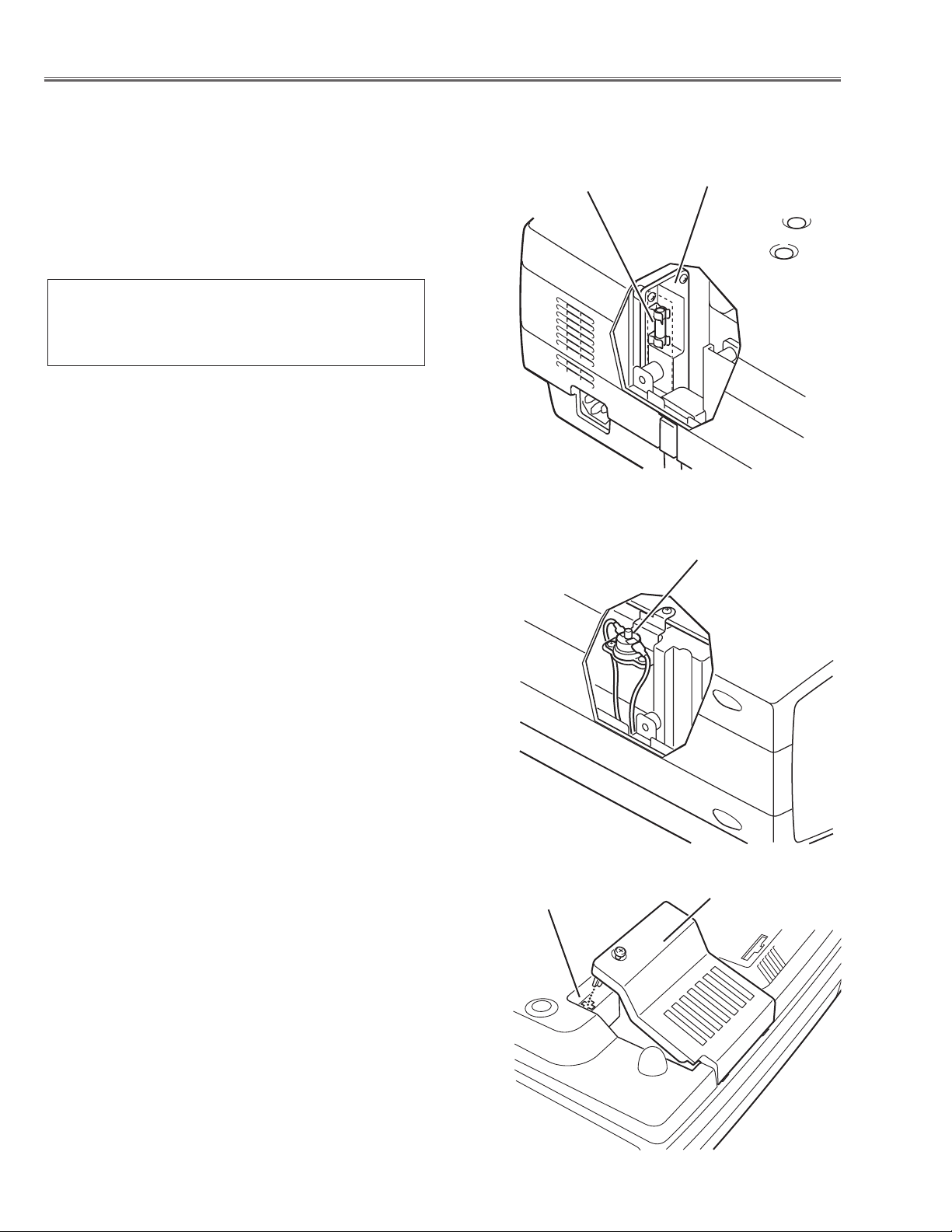
● Interlock switch
The interlock switch (SW902) cuts off the AC mains power supply
when the lamp cover is removed. After opening the lamp cover for
replacing the lamp ass’y, place the lamp cover correctly otherwise
the projector can not turn on.
● Thermal switch
There is the thermal switch (SW905) inside of the projector to
prevent the internal temperature rising abnormally. When the
internal temperature reaches near 90˚C, turn off the AC main
power supply automatically.
The thermal switch is not reset to normal automatically even if the
internal temperature becomes normal. Reset the thermal switch
following procedure.
Check the resistance between terminals of thermal switch by
using the tester. If it has high impedance, thermal switch may be
in operative.
How to reset the thermal switch
1. Remove cabinet top following to the “Mechanical
Disassemblies”.
2. Press the reset button on the thermal switch.
CAUTION:
Before press the reset button, make sure that the AC cord must
be disconnected from the AC outlet.
■ Circuit Protections
This projector provides the following circuit protections to operate in safety. If the abnormality occurs inside the projector, it will automatically turn off by operating one of the following protection circuits.
● Fuse
The fuse is located inside of the projector. When either the LAMP
indicator or the READY indicator is not illuminated, fuse may be
opened. Check the fuse as following steps.
It should be used the specified fuse as follows;
How to replace the fuse
1. Remove the cabinet top following to “Mechanical
Disassemblies”.
2. Remove the fuse from fuse holder.
To install the fuse, take reversed step in the above.
FUSE PART NO. : 645 058 8181
TYPE 8A 250V FUSE
SKYGATE CO. LTD. TYPE SG-5013 008
Fuse
Line Filter Board
Interlock switch
Thermal switch
Lamp cover
-7-
Circuit Protections
● Warning temperature and power failure protection
The projector will be automatically turned off when the internal temperature of the projector exceeds the normal operating temperature, or the cooling fans stops, or the power supplies in the projector are failed.
- If the TEMP WARNING indicator (red) is flashing, it may detect the abnormal temperature inside the projector.
Check the following possible causes and wait until the WARNING TEMP indicator flashing stops, and then try to
turn on the projector.
- If both of the TEMP WARNING (red) and READY (green) indicators are flashing at the same time, It may defect the
cooling fans and power supply circuits. Check fan operation and power supply lines referring to the chapter “Power
supply & protection circuit” in the Chassis Block Diagram section.
Possible causes
- Air filter is clogged with dust particles. Remove dust from the air filter by following instructions in the “Air filter
care and cleaning” below.
- Ventilation slots of the projector are blocked. In such an event, reposition the projector so that ventilation slots are
not obstructed.
- Check if projector is used at higher temperature place (Normal operating temperature is 5 to 35 ˚C or 41 to 95˚F)
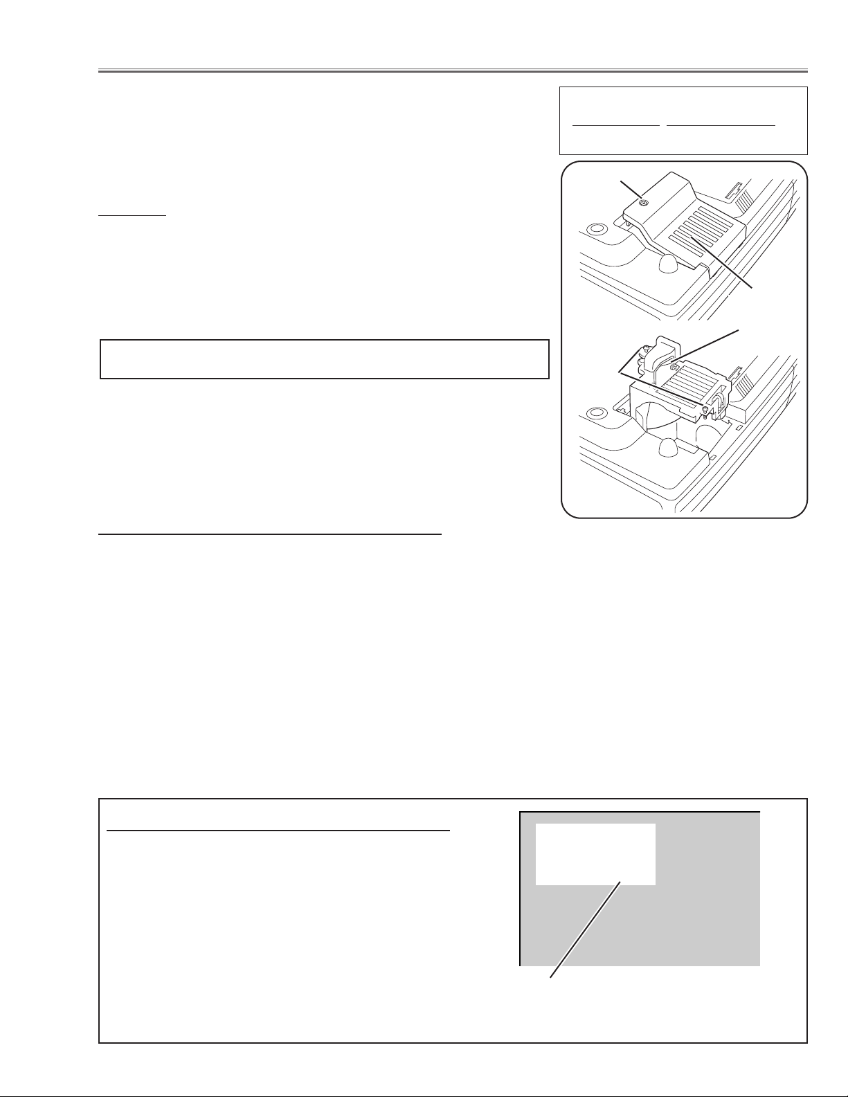
Air filter care and cleaning
The removable air filters prevent dust from accumulation on the surface of the projection lens and projection mirror.
Should the air filter become clogged with dust particles, it will reduce the cooling fan’s effectiveness and may result
in internal heat build up and reduce the life of the projector.
To clean up the air filters, follow the cleaning procedure
below:
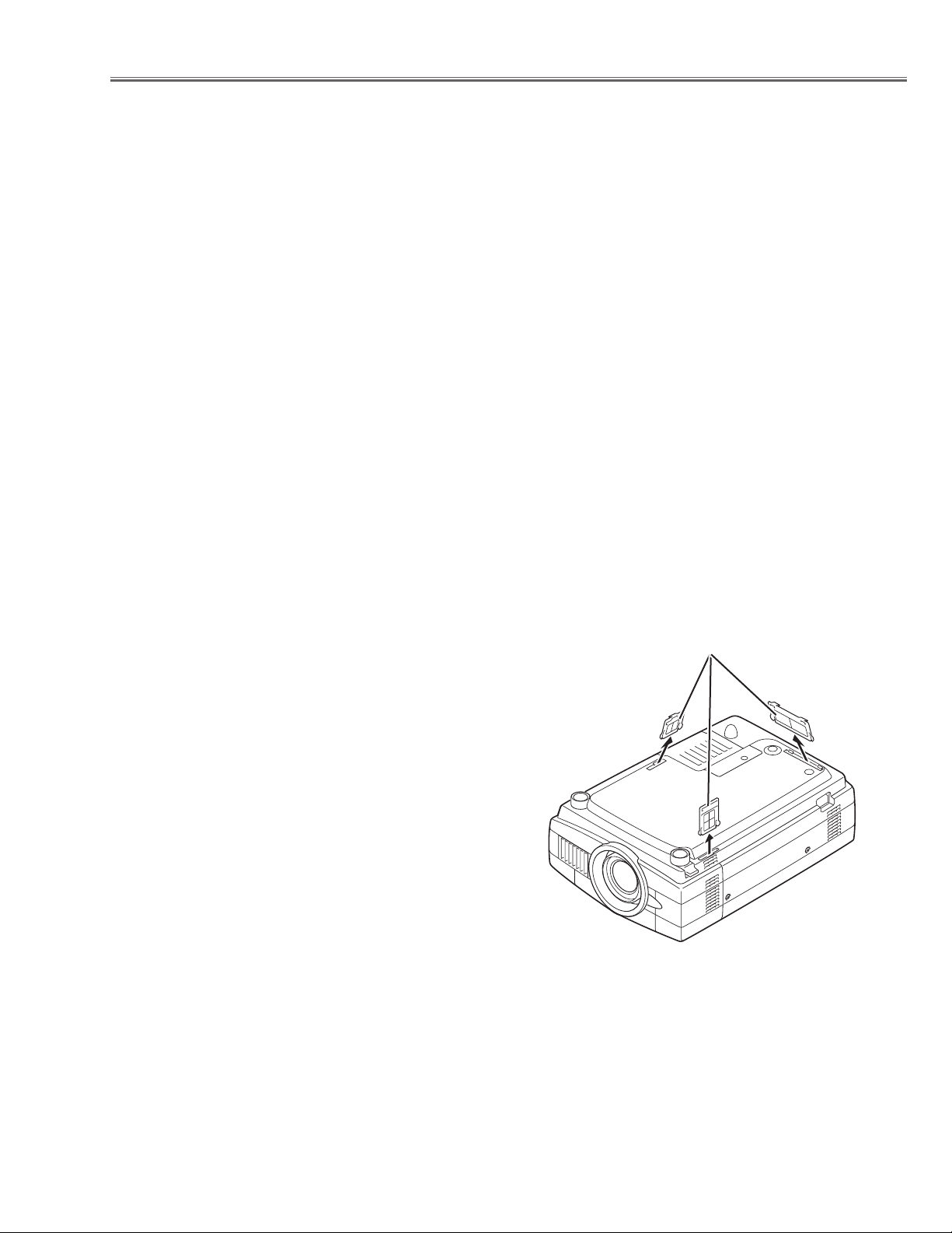
1. Tu rn the power off, and disconnect the AC power cord
from the AC outlet.
2. Tu rn the projector up side down and remove air filters
by pulling the latches of them upward.
3. Clean the air filters with brush or wash out the dust and
particles.
4. Replace each air filter properly. Make sure that the air
filters are fully inserted.
CAUTION:
Do not operate the projector with the air filter removed. The
dust is stuck on the LCD panel and the mirror, and it may
spoil the fine picture image.
Do not put the small parts into the air intake vents. It may
result in the malfunction of the projector. The air filters are
small parts. Take care that children don’t eat or swallow it.
RECOMMENDATION
We recommend not to use the projector in dusty, smoky places. Using it in dusty place may cause the poor picture
quiality.
When using under the dusty or smoky conditions, dust may accumulate on the LCD panel and lens inside it, and
may resultantly be projected on the screen together with the picture.
When the above symptoms are noticed, please clean up the LCD panel and lens following to the “Cleaning
Method”.
Air filters
-8-
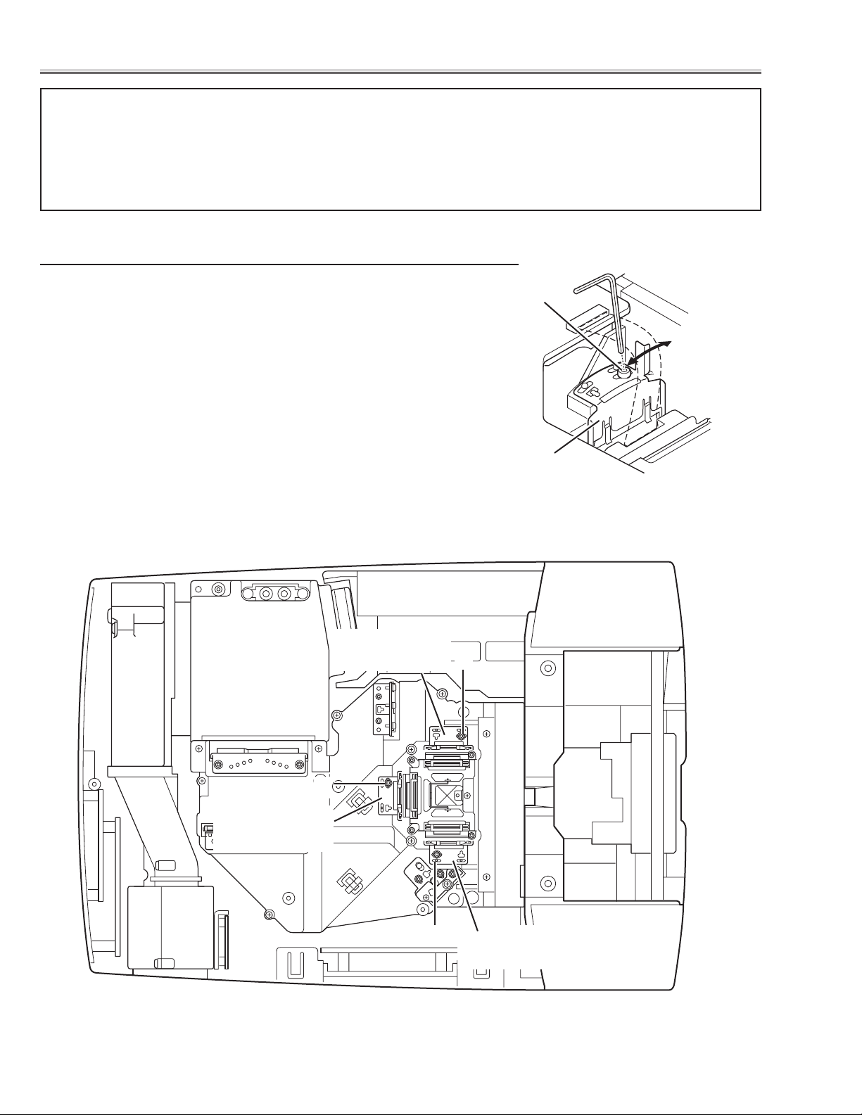
■ Mechanical Disassemblies
Mechanical disassemble should be made following procedures in numerical order.
Following steps show the basic procedures, therefore unnecessary step may be ignored.
Caution:
The parts and screws should be placed exactly the same position as the original otherwise it may cause loss of
performance and product safety.
Fig.1-2
UP
Fig.1-
1
B
B
B
B
B
Cabinet Front-Top
Lens
Front
Cover
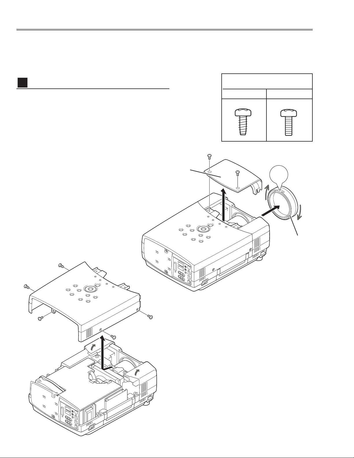
1 Tu rn the Lens Front Cover counter-clockwise and take it
off by pulling forward as shown in Fig.1-1.
2 Remove 2 screws A (M4x10) to take the Cabinet Front-
Top off.
3 Remove 5 screws B (M4x10)
and then take the Cabinet
Top upward off.
Cabinet Top removal
1
Screws Expression
(Type
Diameter x Length) mm
T type M Type
A
A
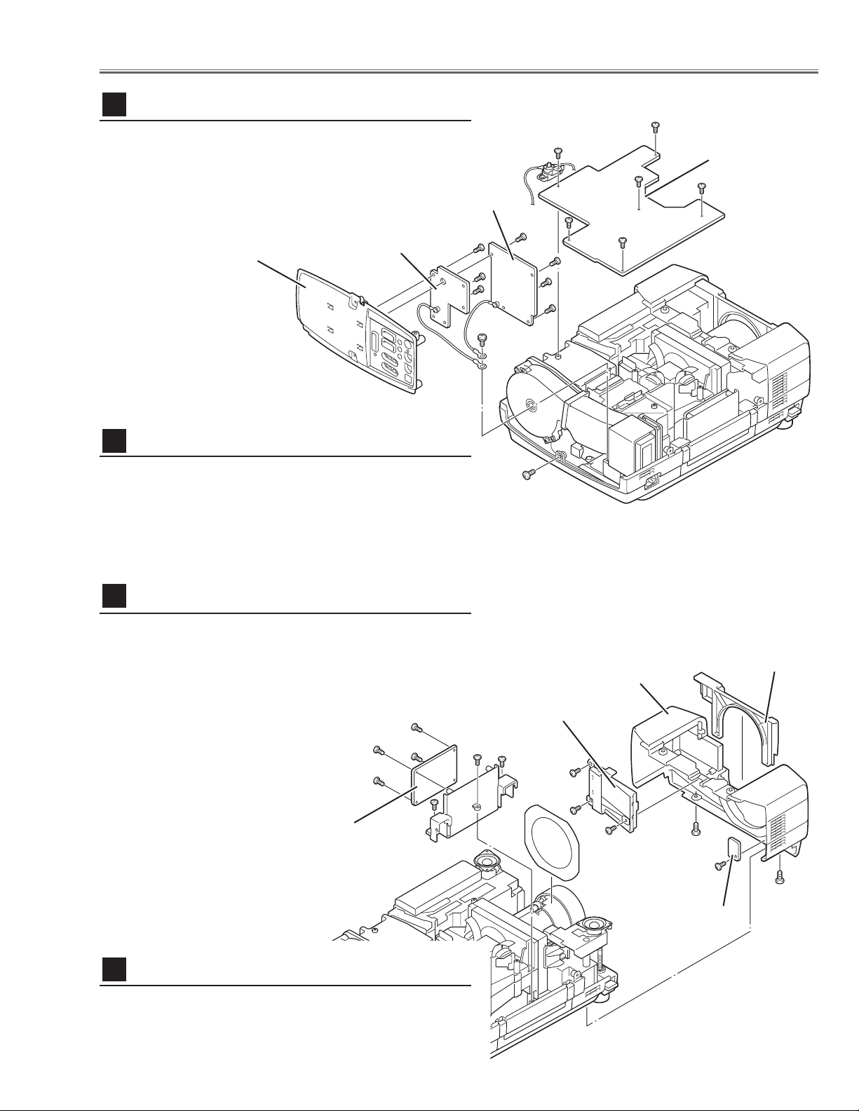
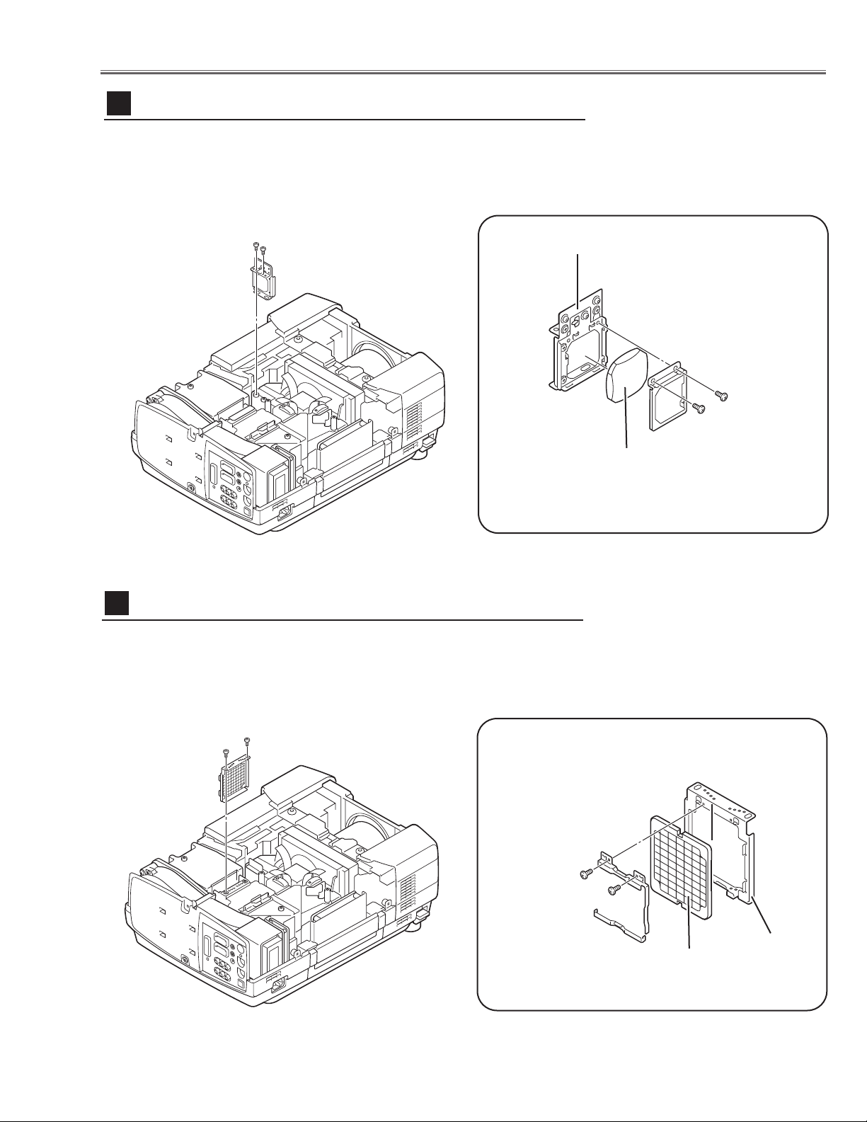
1 Remove 1 screw C (M4x10) and take the Rear Panel
ass’y upward off.
2 Remove 4 screws D (T3x6) to take the AV Board from
the Rear Panel ass’y off.
3 Remove 5 screws E (T3x6) to take the COM Board from
the Rear Panel ass’y off.
-9-
Mechanical Disassemblies
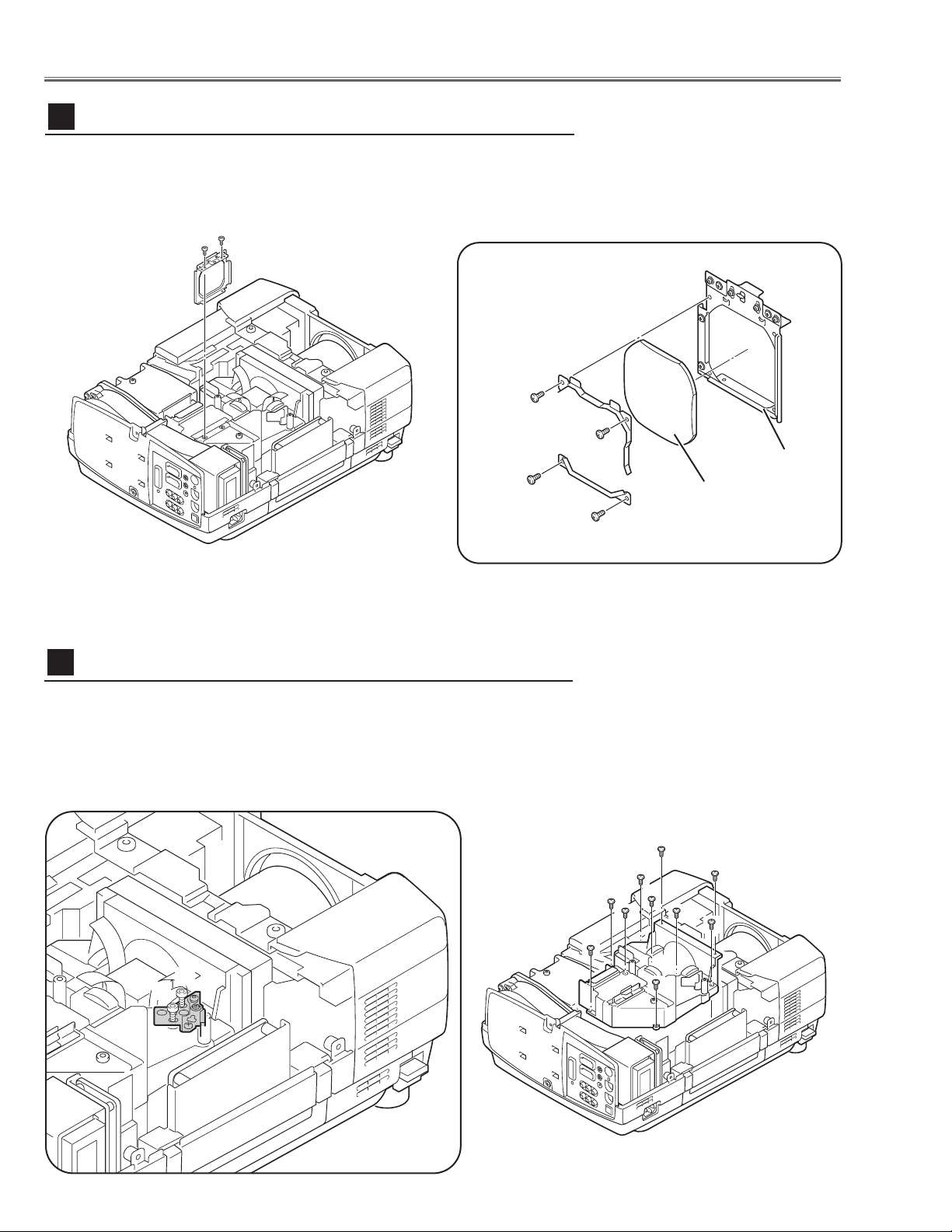
1 Remove 1 screw A (M3x6) to take the thermal
switch(SW905).
2 Remove 5 screws B (M3x6) to take the Main Board
upward.
Fig.2
Fig.3
1 Remove the Lens Cover upward off.
2 Remove 2 screws A (M4x10) and take the Cabinet Front off.
3 Remove 1 screw B (T3x10) and take the R/C Board off.
4 Remove 3 screws C (T3x8) and take the Filter Holder off.
Main Board & Thermal-SW removal
2
Cabinet Front removal
4
Main Board
Rear Panel Ass’y
COM Board
AV Board
A
B
B
D
B
B
B
C
AV , COM Board & Rear Panel removal
3
1 Remove 3 screws D (T3x10) and pull the Holder ass’y
upward off.
2 Remove 4 screws E (T3x8) to take the Audio Board
from the Holder.
Audio Board removal
5
D
D
D
E
E
SW905
A
A
B
C
C
C
D
D
D
E
E
E
E
Lens Cover
Cabinet Front
Filter Holder
R/C Board
Audio Board
-10-
Mechanical Disassemblies
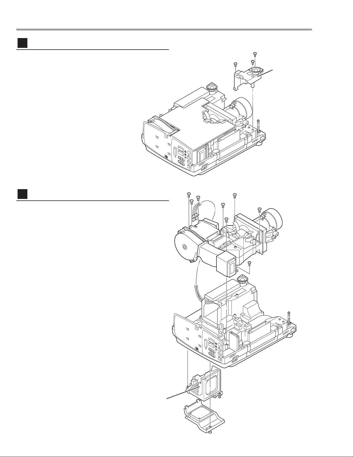
1 Loosen 1 screw A on the lamp cover and 2 screws B on
the lamp house and the take the Lamp House off from
the cabinet bottom.
2 Remove 2 screws C (M3x8) and disconnect the lamp
socket.
3 Remove 5 screws D (T4x10) on the optical unit, 1 screw
E (T3x10) on the duct ass’y and then pull the Optical
Unit upward off.
Fig.5
Optical Unit removal
7
Lamp House
1 Remove 4 screws A (T3x10) and then remove the
Speaker Base.
Speaker base removal
6
Fig.4
A
AA
Speaker Base
A
B
B
C
C
D
D
D
D
D
E
-11-
Fig.7
A
Ballast Board
FN905
Power DC
Board
A
A
AB
B
Ballast Cover
Mechanical Disassemblies
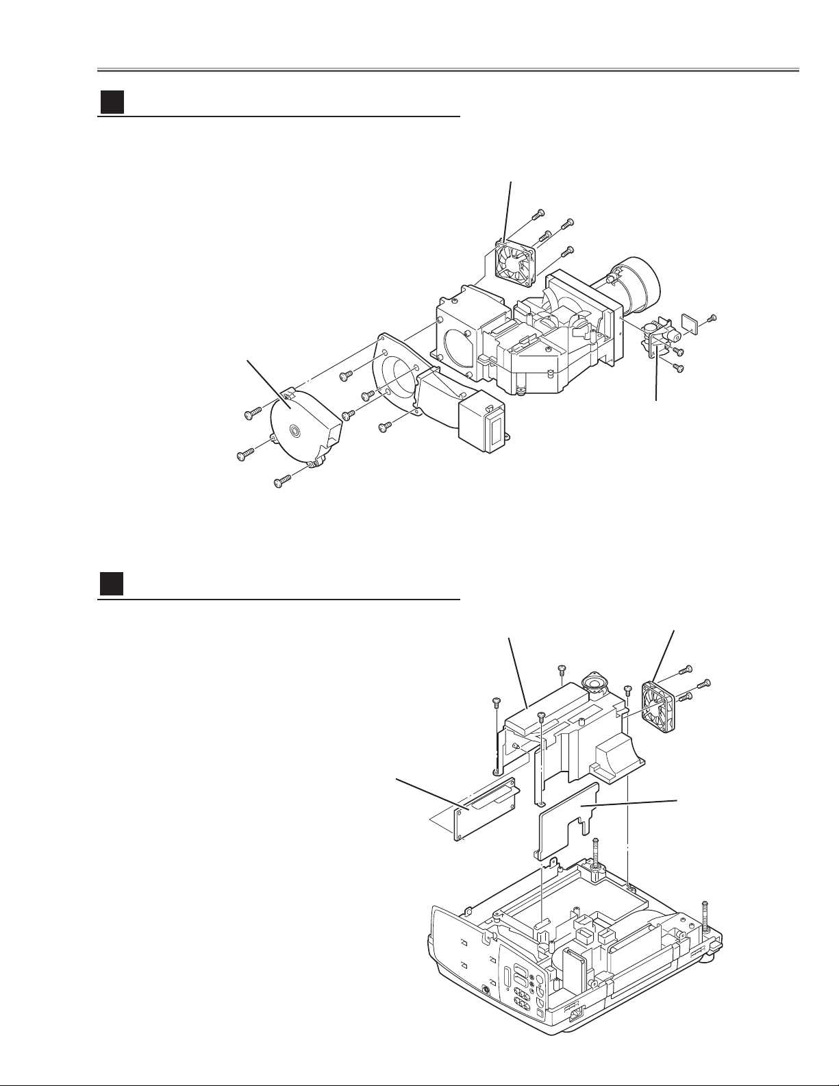
1 Remove 4 screws A (T3x8) and then pull the Ballast
Board Ass’y upward off.
2 Remove 3 screws B (T3x20) to take the Fan (FN905) off.
3 Unhook 4 hooks and take the Lamp Ballast Board off.
4 Disconnect the Power DC board from the Power AC
board.
Lamp Ballast Board removal
9
1 Remove 4 screws A (T3x20) to take the fan (FN904) off.
2 Remove 3 screws B (T4x25) to take the fan (FN907) off.
3 Remove 4 screws C (T3x10) to take the duct ass’y off.
4 Remove 2 screws D (T3x6) to take the Lens Shift Motor
and Sensor SW Holder from the Base.
Fan & Motor removal
8
Motor and
Sensor Holder
Fig.6
A
A
AA
B
B
B
C
C
C
C
D
D
B
FN904
FN907
-12-
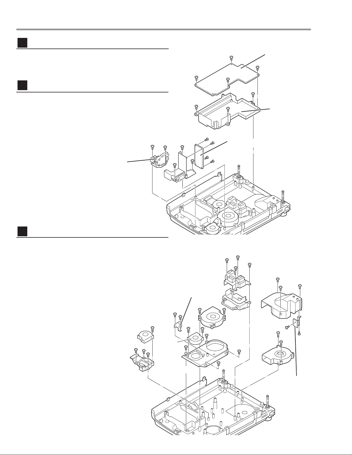
1 Remove 3 screws C (T3x10) to take the Filter Board
Ass’y upward.
2 Remove 3 screws D (T3x8) and 1 screw E (T3x6) to
take the Filter Board from the Holder.
3 Remove 2 screws F (T3x10) to take the Interlock switch
(SW902) from the cabinet bottom.
1 Remove 1 screw A (T3x20) then take the Fan (FN906) off
and remove 3 screws B (T3x10) to take the Duct-A off.
2 Remove 4 screws C (T3x10) to take the Duct-B off.
3 Remove 3 screws D (T3x10) to take the Duct-C off,
remove 1 screw E (T3x10) and 1 screw F (T3x6) to take
the Sensor Board off.
4 Remove 2 screws G (T4x25) to take the Fan (FN902) off.
Remove 2 screws H (T4x25) to take the Fan (FN901) off.
5 Remove 2 screws J (T3x8) to take the Duct Cover off and
remove 2 screws K (T4x25) to take the Fan (FN903) off.
6 Remove 4 screws L (T3x10) to take the Duct-D off.
Fig.9
Fans (FN901, FN902) removal
12
Line Filter Board & Interlock SW removal
11
Mechanical Disassemblies
1 Remove 4 screws A ( T3x6) to take the Power Board off.
2 Remove 4 screws B (T3x10) to take the Holder from the
cabinet bottom.
Fig.8
Power AC Board removal
10
Power AC
Board
Power Board
Holder
B
C
A
A
BB
A
Interlock Switch
(SW902)
Filter Board
A
C
E
D
D
D
F
F
C
Duct-C
Duct-A
Duct-D
Duct-B
Duct
Cover
Sensor Board
A
FN906
B
FN903
B
B
J
J
L
C
C
C
C
H
H
K
K
L
FN901
L
FN902
L
D
D
D
G
F
G
E
-13-
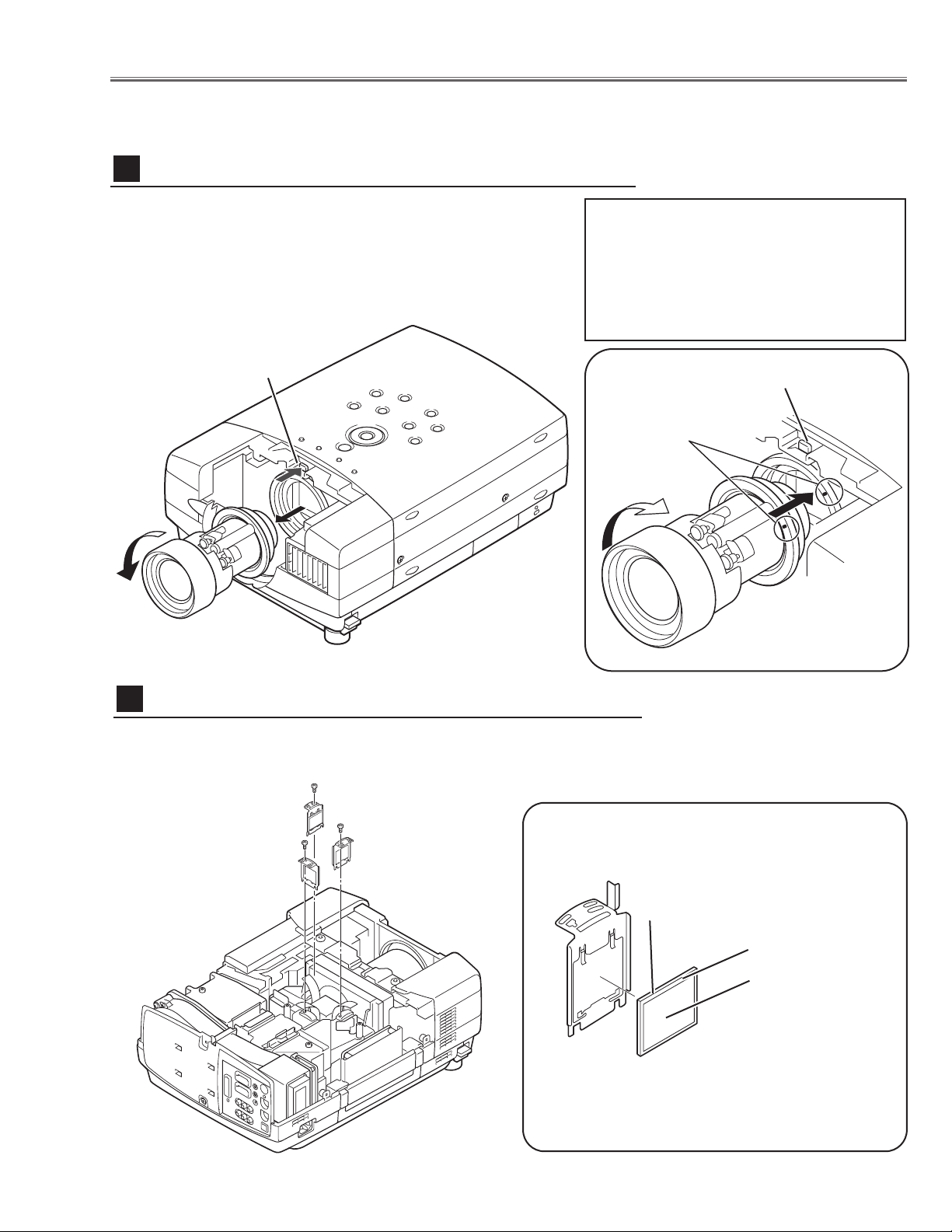
1 Shift the projection lens to the end of top position by pressing
the Lens Shift (+) button.
2 Remove the Cabinet Front-Top and Lens Holder following to
the chapter “Mechanical Disassemblies”.
3 Press and hold the Fixing Lever A and turn the Projection
Lens counter-clockwise(1/6 turn) and then take it off.
Fig.1-
1
■ Optical Parts Disassemblies
Before taking this procedure, remove Cabinet Top and Main Board following to the “Mechanical Disassemblies”.
Disassembly requires a 2.0mm hex wrench.
Projection Lens removal
1
Fig.1-2
1 Remove each hex screw and pull the Polarized Glass-In ass’y upward.
2 Remove a stopper and take the glass off upward.
Polarized Glass-In removal
2
Fig.2-
1
* Glass should be placed as the
printed marker comes to the
upper left corner.
Fig.2-2
polarized glass
Phase Sheet
Part No. is printed on
upper side.
Lever-A
Lever-A
Point Markers
Note in the Mounting Projection
Lens
Insert the Projection lens into the guide at a
position where the both markers on the projection lens and the mounting base come
together, and turn it clockwise until the Fixing
Lever is set to the fixing position.
Note:
Do not replace the LCD panel
separately otherwise it can
not obtain proper picture.
-14-
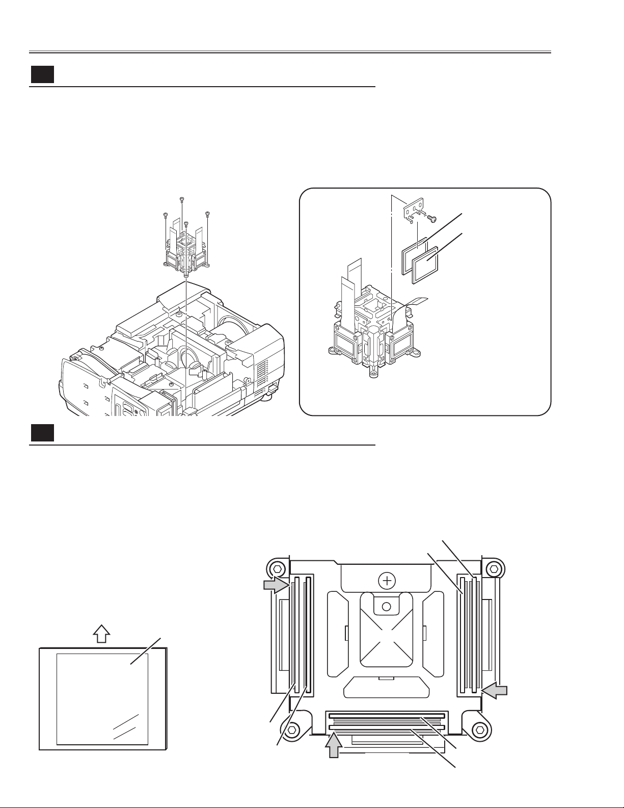
1 Remove 4 hex screws A and take the LCD/Prism ass’y off upward.
2 Remove each 1 screw B and take the Glass Holder, and then pull the
Optical filter, Polarized Glass-Out upwards off. These glasses are mounted
for R, G and B LCD panels respectively.
Note:
To avoid the CG and focus alignments slipping off, please be careful to handle the LCD/Prism ass'y.
* Glasses should be placed as the
sheet attached side comes to the
LCD panel side.
Prism ass’y removal and disassembly
3-
1
A
A
A
Optical Pats Disassemblies
B
Polarized GlassOut
A
Fig.3-2
Fig.3-
1
Optical Filter
The polarized glasses and optical filters in the prism assembly are installed
as figure below. Please be careful for the mounting.
The polarized glasses are placed as the film attached face comes outside.
The optical filters are placed as the face on which the part no. is printed
comes to the arrow direction as shown in the figure. The optical filters for B
and G panel have films on the both of the faces.
Optical Filter
Polarized Glass-Out
To p
Prism
Optical Filter
Polarized Glass-Out
Polarized Glass-Out
Optical Filter
G-Panel
G-Panel
B-Panel
Film
Polarized glass and optical filter mounting direction
3-
2
Fig.3-3
Fig.3-4
1AV4Z15Bxxxx
-15-
Optical Parts Disassemblies
1 Remove 2 hex screws A and pull the Relay Lens ass’y upward.
2 Remove 2 screws B to take the Lens off from the holder.
Note:
There is no mounting direction of the lens.
A
Fig.4-1
B
B
Holder
Relay Lens
A
Relay Lens disassembly
4
1 Remove 2 hex screws A and take the Integrator Lens ass’y.
2 Remove 2 screws B to take the Lens off from the holder.
A
Fig.5-
2
Fig.5-1
B
Holder
A
Integrator-In disassembly
5
*Lens should be placed
as the flat surface side
comes to the holder
side.
Fig.4-2
B
Integrator-In
-16-
1 Loosen 2 screws A on the holder on the optical unit.
2 Remove 7 screws B to take the Optical Unit Top off upward.
Note in Mounting of the Optical Unit Top
After mounting the Optical Unit Top, mount the holder for fixing the Mirror in
the optical unit.
Optical Unit Top removal
7
A
B
B
B
B
A
Fig.7-1
Fig.7-2
1 Remove 2 hex screws A and take the Condenser Lens ass’y.
2 Remove 4 screws B to take the Lens off from the holder.
A
Fig.6-2
Fig.6-1
B
Holder
Condenser Lens
A
Condenser Lens disassembly
6
*Lens should be placed
as the flat surface side
comes to the holder
side.
B
B
B
-17-
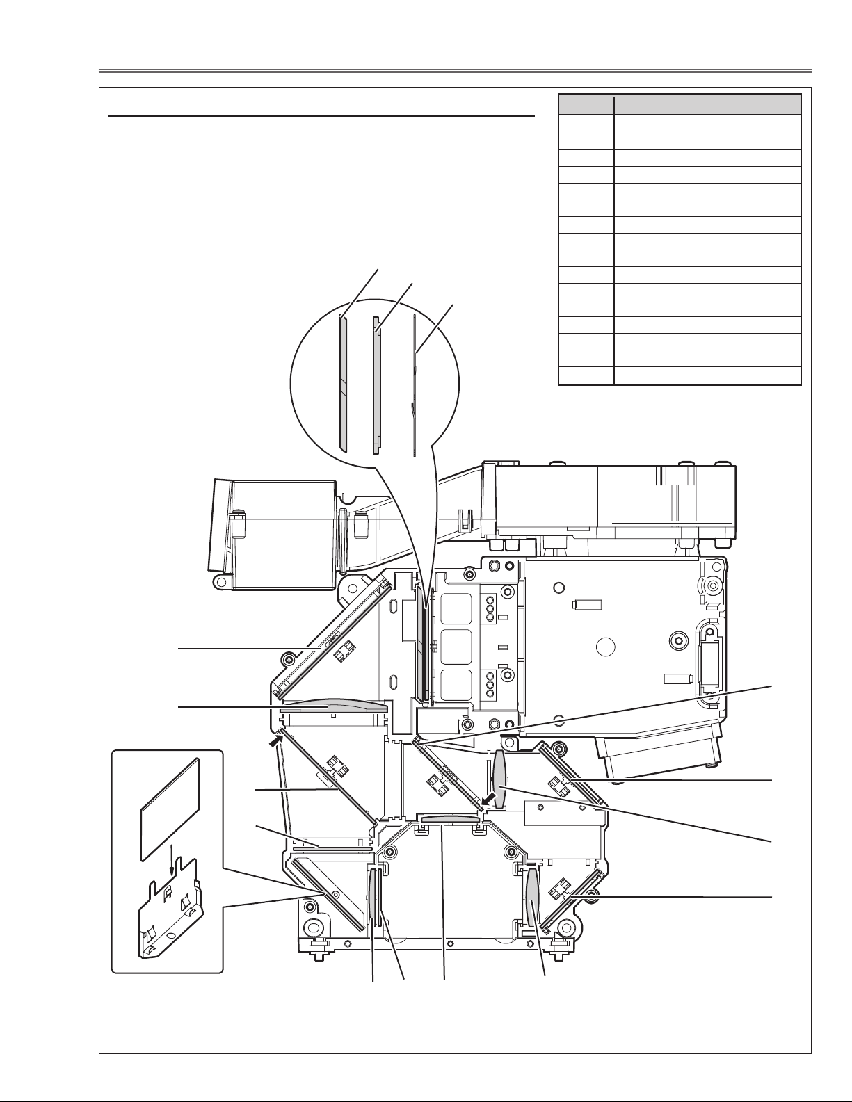
Optical Parts Disassemblies
When the optical parts in the optical unit mounting or assembling, the
parts must be mounted in the specified location and direction as
shown in figure below.
Note: The arrow in the figure below is indicated that there is the direc-
tion of part placement. Place each part as the printed marker on
the part comes to each arrow direction.
The key No. 16 should be placed as the film attached side
comes to the mirror side.
14
10
8
Fig.8
3
1
2
9
Locations and Directions
5
6
1 Slit-Int
2Integrator Lens-Out
3 PBS (Prism Beam Splitter)
4 Mirror (W-Cold)
5 Condenser lens-Out
6 Dichroic mirror (B)
7 Optical Filter (UV Cut)
8 Mirror Holder
9 Mirror (B)
10 Condenser lens
11 Dichroic Mirror (G)
12 Condenser Lens (G)
13 Relay lens-In
14 Mirror (R)
15 Condenser Lens (R)
16 Pre-polarized glass (B)
Key No. Description
4
12
11
7
13
15
14
16
-18-
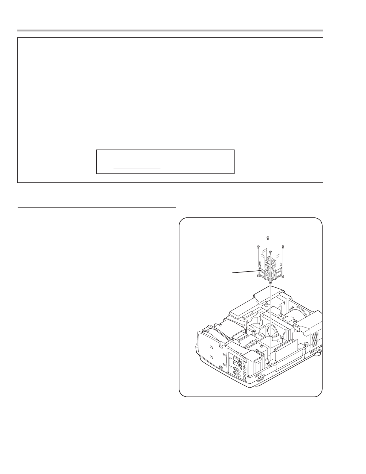
■ LCD Panel/Prism Ass’y Replacement
1 Remove the cabinet top and main board following to
“Mechanical Disassemblies”.
2 Remove 3 Polarized Glass-In.
3 Remove 4 screws by using the 2.0 mm hex driver and
take the LCD Panel/Prism ass’y off upward from the
optical unit.
LCD Panel/Prism
Ass’y
Note:
Do not replace the LCD
panel separately otherwise
it can not obtain proper picture.
IMPORTANT NOTICE on LCD Panel/Prism Ass'y Replacement
LCD panels used for this model can not be replaced separately. Do not disassemble the LCD Panel/Prism Ass’y.
These LCD panels are installed with precision at the factory. When replacing the LCD panel, should be replaced
whole of the LCD panels and prism ass’y at once.
After replacing LCD Panel/Prism ass’y, please check the following points.
- Check that there is no color shading at the top, bottom, left or right of the screen. If there is, try to
remove the shading following to the chapter “Optical Adjustment”.
- Check the white balance. If it needs the adjustment, adjust the white balance following to the “White
Balance Adjustment” and “Common Centre Adjustment” in the chapter “Electrical Adjustment”.
- Check the white uniformity on the screen.
If you find the color shading at the some part of the screen, it needs to take the color shading adjustment. This adjustment should be performed by a computer and it also requires a special software
“Color Shading Correction”. The software will be supplied separately and can be ordered as follows;
COLOR SHADING CORRECTION SOFTWARE
Ser
vice Parts No
. 645 051 2308
LCD Panel/Prism Ass’y removal
The LAMP REPLACEMENT indicator will illuminate
when the Lamp Replace Counter reaches 1000
hours. This is to indicate that lamp replacement is
required.
You can check the lamp replace counter following to
below procedure.
1 Press and hold the pointer e on the projector for
more than 20 seconds.
2 The Lamp replace Counter is displayed on top left
corner of the screen briefly.
-19-
WARNING:
- For continued safety, replace with a lamp assembly of the same type.
- Allow the projector to cool for at least 45 minutes before you open the
lamp cover. The inside of the projector can become very hot.
- Do not drop the lamp module or touch the glass bulb! The glass can
shatter and cause injury.
Procedure
1 Tu rn off the projector and disconnect the AC cord. Allow the projector to
cool for at least 45 minutes.
2 Loosen 1 screws with a screwdriver and open the lamp cover.
3 Loosen 2 screws and pull out the lamp assembly by grasping the handle.
4 Replace the lamp assembly securely and tighten 2 screws.
5 Close the lamp cover and tighten 1 screw.
6 Connect the AC cord to the projector and turn on.
Note:
- Do not reset the Lamp Replace Counter, except after lamp is replaced.
- The projector can not be turned-on with lamp cover removed, because
when the lamp cover is removed, the interlock switch is also released to
switch off the mains power for safety.
7 Reset the Lamp Replace Counter, see below explanation.
■ Lamp Replacement
1 Tu rn the projector on, and press the MENU button
and the on-screen menu will appear. Press the 7 or 8
button to move a red frame pointer to SETTING menu
icon.
2 Press the e button to move a red frame pointer to
“Lamp counter reset” and then press the SELECT
button.The message “Lamp replace counter reset?” is
displayed. Move the pointer to [Yes] and the press the
SELECT button.
3 Another confirmation dialog box appears and select
[Yes] to reset Lamp Replace Counter .
Please refer to the owners manual for further information.
Recommendation
Should the air filter become clogged with dust particles,
it will reduce the cooling fan’s effectiveness and may
result in internal heat build up and short lamp life. We
recommend cleaning the air filter after the projection
lamp is replaced.
Refer to “Air Filter Cleaning”.
Lamp cover
Lamp replace counter data
ORDER REPLACEMENT LAMP
T
ype No.
Service Parts No.
POA-LMP48 610 301 7167
How to reset Lamp Replace Counter
How to check Lamp Replace Counter
Screws
Handle
Screws
Normal 123 h
Eco 250 h
Total 373 h
-20-
[Before Adjustment]
- Input a 100% of black raster signal.
[R/G/B-CONTRAST ADJUSTMENT]
1 Loosen a screw A (Fig.1-1/1-2) on the polarized glass mounting
base which you intend to adjust.
2 Tu rn the polarized glass mounting base as shown in Fig.1-1 to
obtain the darkest brightness on the screen.
3 Tighten the screw A to fix the polarized glass mounting base.
Repeat steps 1 to 3 for remaining polarized glasses.
B-Polarized Glass
Mounting Base
R-Polarized Glass
Mounting Base
G-Polarized Glass
Mounting Base
A
A
A
Fig.1-2
Fig.1-1
Polarized glass
mounting base
■ Optical Adjustments
A
Contrast adjustment
Before taking optical adjustments below, remove the Cabinet Top and Main Board, if required, following to the
“Mechanical Disassemblies”
Adjustments require a 2.0mm hex wrench and a slot screwdriver.
Note: Do not disconnect connectors K8E, K8F, K8G, K8J and K8K on the main board, because the projector can
not turn on due to operate the power failure protection.
-21-
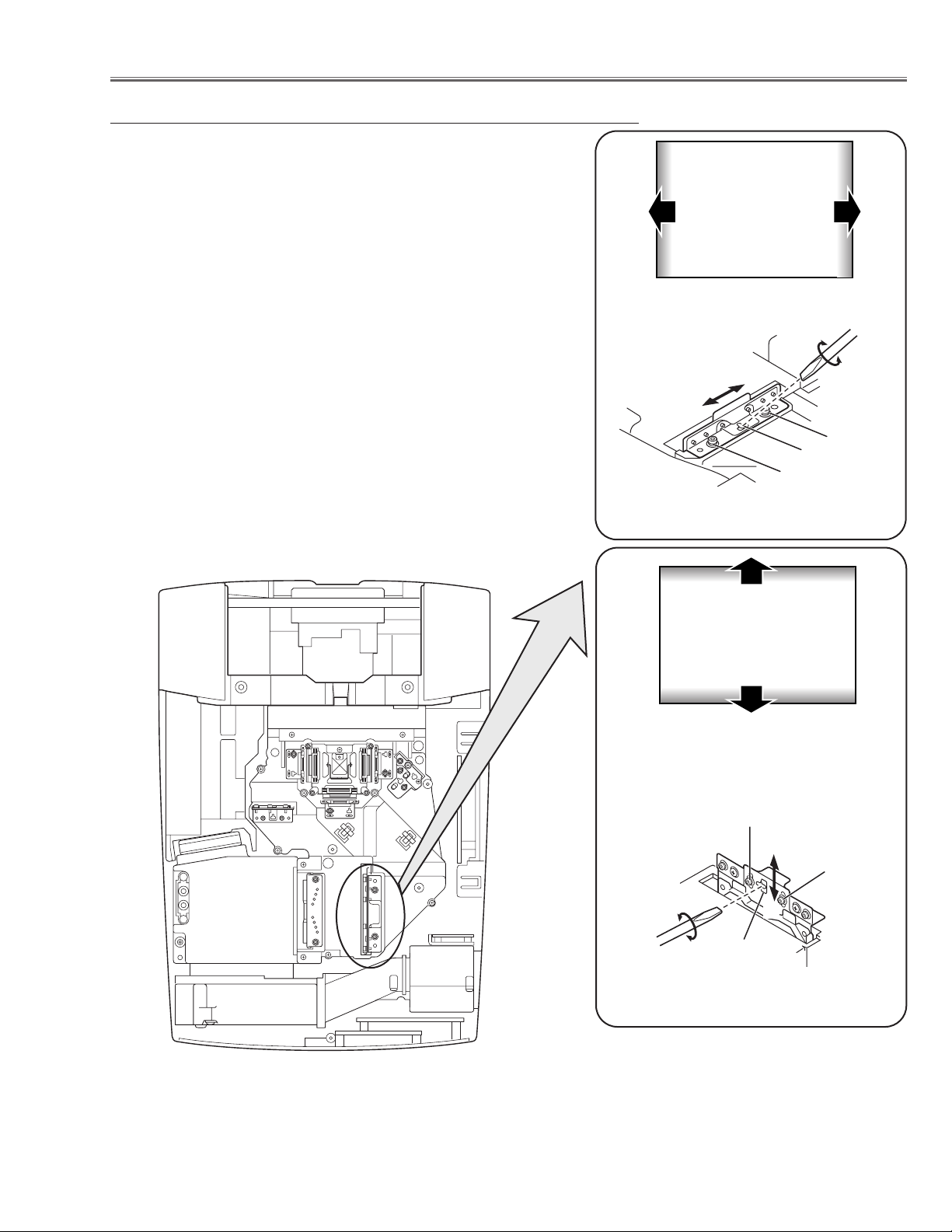
Optical Adjustments
Fig.2-2
1 Tu rn the projector on by a state of without FPC cables.
2 Adjust the adjustment base of condenser lens ass’y to make color
uniformity in white.
1) If the shading appears on the left or right of the screen as
shown in Fig.2-1, loosen 2 screws A with the 2.0mm hex driver, and adjust the slot B to make color uniformity in white by
using a slot screwdriver.
2) If the shading appears on the top or bottom of the screen as
shown in Fig.2-2, loosen 2 screws C with the 2.0mm hex driver, and adjust the slot D to make color uniformity in white by
using a slot screwdriver
3 Tighten screws A and C to fix the Condenser lens unit.
Note:
The relay lens adjustment must be carried out after completing this
adjustment.
y
x
Moving of Slot D
a
b
Moving of Slot B
Fig.2-1
White
White
Condenser Lens adjustment
b
a
A
B
A
C
x
C
y
D
-22-
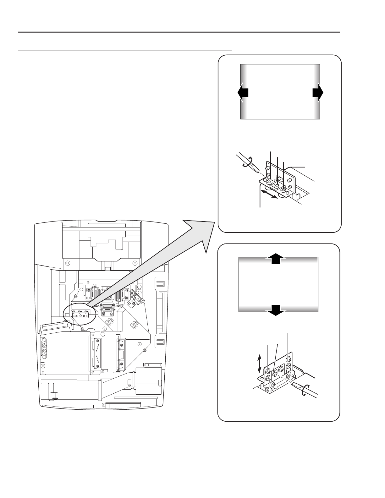
1 Tu rn the projector on by a state of without FPC cables.
2 Adjust the adjustment base of relay lens ass’y to make color unifor-
mity in white.
1) If the shading appears on the left or right of the screen as shown
in Fig.3-1, loosen 2 screws A with the 2.0mm hex driver, and
adjust the slot B to make color uniformity in white by using a slot
screwdriver.
2) If the shading appears on the top or bottom of the screen as
shown in Fig.3-2, loosen 2 screws C with the 2.0mm hex driver,
and adjust the slot D to make color uniformity in white by using a
slot screwdriver.
3 Tighten the screws A and C to fix the relay lens unit.
Fig.3-1
a
Moving of Slot B
b
White
Fig.3-2
Moving of Slot D
y
x
Relay Lens-Out adjustment
White
Optical Adjustments
A
B
A
a
b
C
x
y
C
D
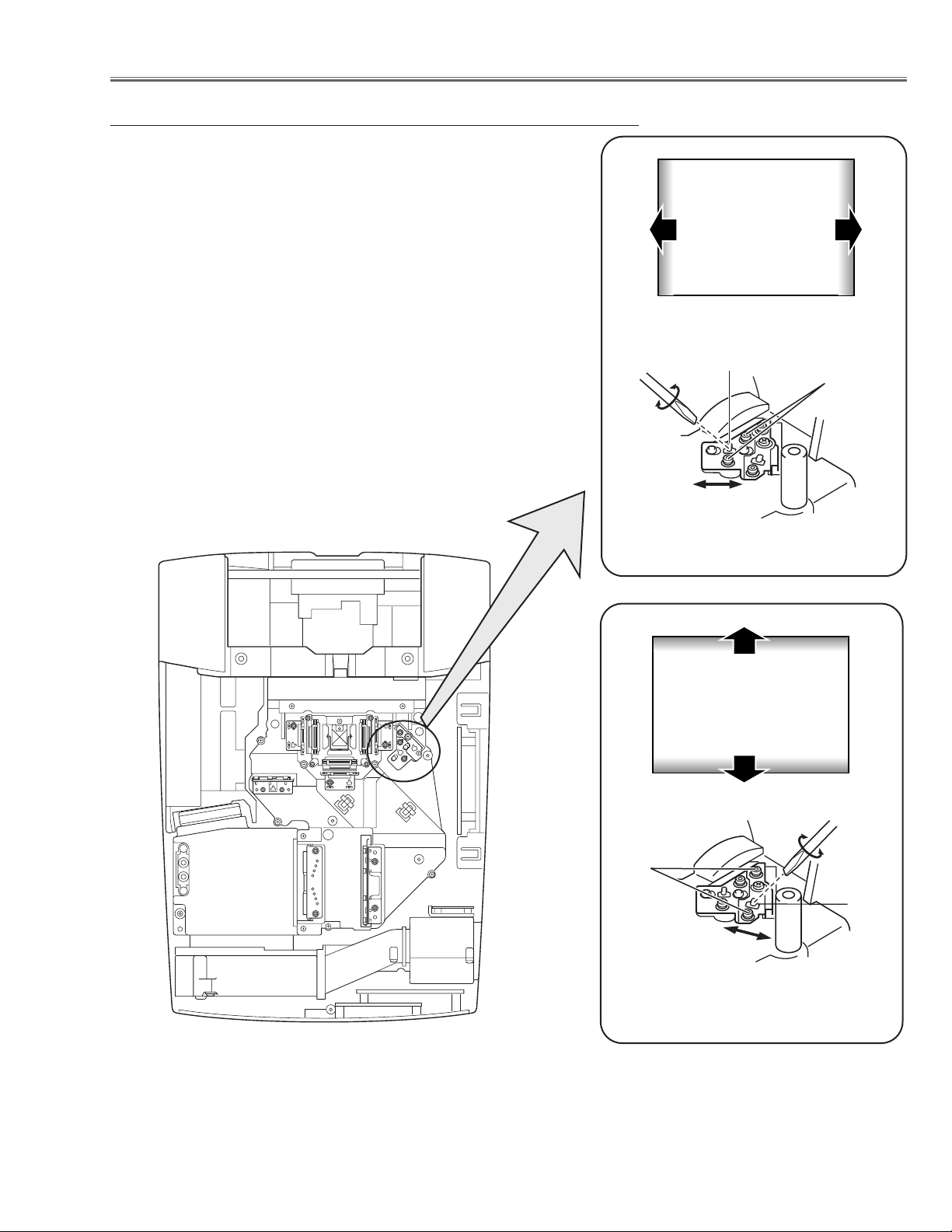
Fig.4-1
a
Moving of Slot B
b
White
Fig.4-2
Moving of Slot D
y
x
White
-23-
1 Tu rn the projector on by a state of without FPC cables.
2 Adjust the adjustment base of mirror to make color uniformity in
white.
1) If the shading appears on the left or right of the screen as shown
in Fig.4-1, loosen 2 screws A with the 2.0mm hex driver, and
adjust the slot B to make color uniformity in white by using a slot
screwdriver.
2) If the cyan bar appears on the top or bottom of the screen as
shown in Fig.4-2, loosen 2 screws C with the 2.0mm hex driver,
and adjust the screw D to make color uniformity in white by using
a slot screwdriver.
3 Tighten the screws A and C to fix the relay lens unit.
Mirror adjustment
Optical Adjustments
B
A
a
C
x
b
D
y
-24-
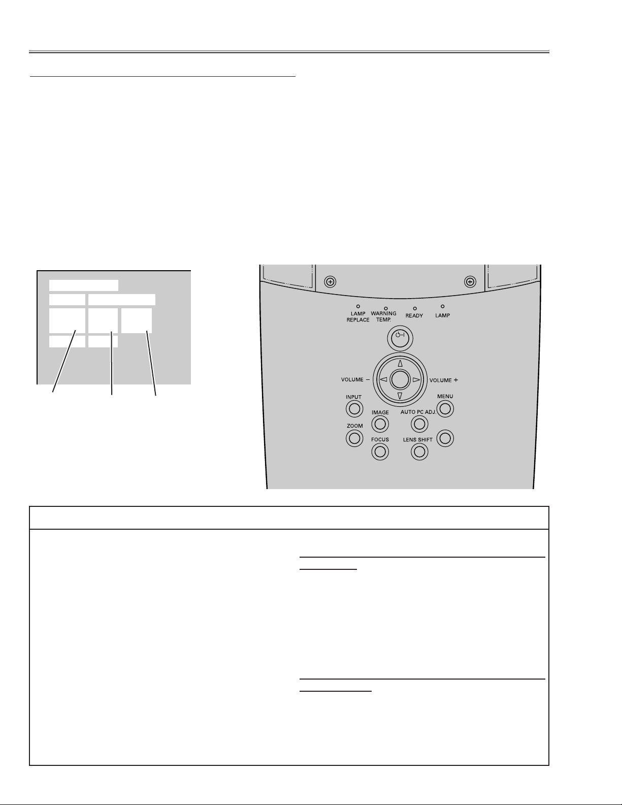
■ Electrical Adjustments
To enter the service mode
To enter the “Service Mode”, press and hold the MENU and IMAGE button on the projector at the same time for
more than 3 seconds. The service menu appears on the screen as follows.
To adjust service data
Select the adjustment group no. (Group) by pressing the MENU(+) button or IMAGE(-) button, and select the
adjustment item no. (No.) by pressing the e or d button, and change the data value (Data) by pressing the 7 or
8 button. Refer to the “Service Adjustment Data Table” for further description of adjustment group no., item no.
and data value.
To exit the service mode
To exit the service mode, press the POWER ON-OFF button on the projector or remote control unit.
● Service Adjustment Menu Operation
IC808 on the main board stores the data for the service adjustments, and should not be replaced except for
the case of defective device.
If replaced, the re-adjustments are required following to
the “Electrical Adjustments”.
The data of lamp replacement counter is stored in the
IC808.
Please note that the lamp replace counter will be reset
when the memory IC (IC808) is replaced.
(Lamp replace counter can not be set to the previous
value.)
● Caution to memory IC replacement
When IC808 is replaced with new one, the CPU writes
down the default data of the service adjustments to the
replaced IC as the mentioned on the service adjustment table. As these data are not the same data as factory shipped data, it should be required to perform the
re-adjustments following to the “Electrical Adjustments”.
Please note that in this case the lamp replace counter
will be reset.
● Caution of Main Board replacement (in the case
IC808 is not defective)
When the main board is replaced, IC808 should be
replaced with the one on previous main board. After
replacement, it should be required to perform the readjustments following to the “Electrical Adjustments”.
In this case, the lamp replace counter can be kept the
v
alue as before.
● Memory IC Replacement
Group No.
Data value
Item No.
Service Mode
Input Computer 1
Group No. Data
0032
Ver. 1.00
ON-OFF
SELECT
KEYSTONE
-25-
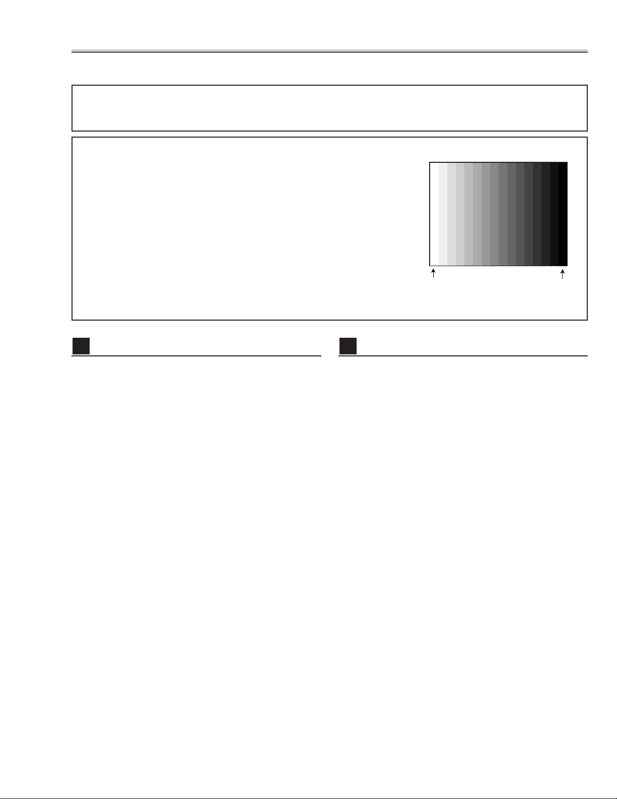
[Adjustment Condition]
● Input signal
Video signal .......................... 1.0Vp-p/75Ω terminated, 16 steps gray
scale (Composite video signal)
Computer signal .................... 0.7Vp-p/75Ω terminated, 16 steps gray
scale pattern (XGA)
Component Video signal ...... 0.7Vp-p/75Ω terminated, 16 steps gray
scale (Component video signal with
480p or 1080i format)
● Picture control mode .............. “STANDARD” mode unless otherwise
noted.
Note:
* Please refer to “Service Adjustment Menu Operation” for entering the service mode and adjusting the service data.
● Circuit Adjustments
CAUTION: The each circuit has been made by the fine adjustment at factory. Do not attempt to adjust the follow-
ing adjustments except requiring the readjustments in servicing otherwise it may cause loss of performance and product safety.
Electrical Adjustments
1. Receive the 16-step gray scale computer signal with
Computer 1 [Analog RGB] mode.
2. Enter the service mode.
3. Connect a digital voltmeter to test point “TP531”(+)
and chassis ground (-).
4. Select group no. “5”, Item no. “0” and adjust the voltage to be 7.50 ±0.1Vdc by changing the Data value.
5. Connect a digital voltmeter to test point “TP501”(+)
and chassis ground (-).
6. Select Item no. “1” and adjust the voltage to be 7.50
±0.1Vdc by changing the Data value.
7. Connect a digital voltmeter to test point “TP561”(+)
and chassis ground (-).
8. Select Item no. “2” and adjust the voltage to be 7.50
±0.1Vdc by changing the Data value.
Video Center adjustment
2
16 steps gray scale pattern
1. Set the lamp mode to “ECO” with the menu function.
2. Enter the service mode and select group no. “11” and
Item no. “5”. Set Data value to “1”.
3. Connect a digital voltmeter to test point “TPFAN1”(+)
and chassis ground (-).
4. Select group no. “11”, Item no. “86” and adjust the voltage to be 4.5 ±0.1Vdc by changing the Data value.
Select Item no. “87” and adjust the voltage to be 13.8
±0.1Vdc by changing the Data value.
5. Connect a digital voltmeter to test point “TPFAN2”(+)
and chassis ground (-).
6. Select Item no. “88” and adjust the voltage to be 4.5
±0.1Vdc by changing the Data value.
Select Item no. “89” and adjust the voltage to be 13.8
±0.1Vdc by changing the Data value.
7. Connect a digital voltmeter to test point “TPFAN2”(+)
and chassis ground (-).
8. Select Item no. “90” and adjust the voltage to be 4.5
±0.1Vdc by changing the Data value.
Select Item no. “91” and adjust the voltage to be 13.8
±0.1Vdc by changing the Data value.
9. Select group no. “11” and Item no. “5”. Set Data value
to “0”, and set the lamp mode to “Normal” with the
menu function.
Fan Voltage adjustment
1
White 100%
Black 100%
-26-
Electrical Adjustments
1. Receive the 16-step gray scale computer signal with
Computer 1 [Analog RGB] mode.
2. Enter the service mode.
3. Connect an oscilloscope to test point “TP531” (+) and
chassis ground (-).
4. Select group no. “5”, Item no. “11” and adjust the
black level to be maximum amplitude by changing the
Data value.
5. Connect an oscilloscope to test point “TP501” (+) and
chassis ground (-).
6. Select Item no. “12” and adjust the black level to be
maximum amplitude by changing the Data value.
7. Connect an oscilloscope to test point “TP561” (+) and
chassis ground (-).
8. Select Item no. “13” and adjust the black level to be
maximum amplitude by changing the Data value.
Pedestal adjustment [PC]
4
1. Receive the 16-step gray scale computer signal with
Computer 1 [Analog RGB] mode.
2. Enter the service mode.
3. Connect an oscilloscope to test point “TP2531”(+)
and chassis ground (-).
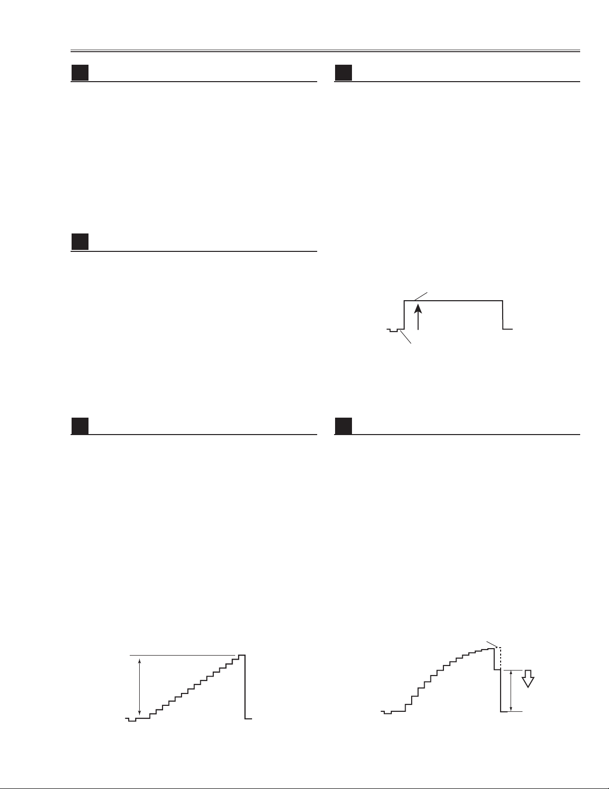
4. Select group no. “5”, Item no. “7” and adjust the amplitude “a” to be 2.0 ±0.1V by changing the Data value.
5. Select Item no. “6” and adjust the amplitude “b” to be
7.5 ±0.1V by changing the Data value.
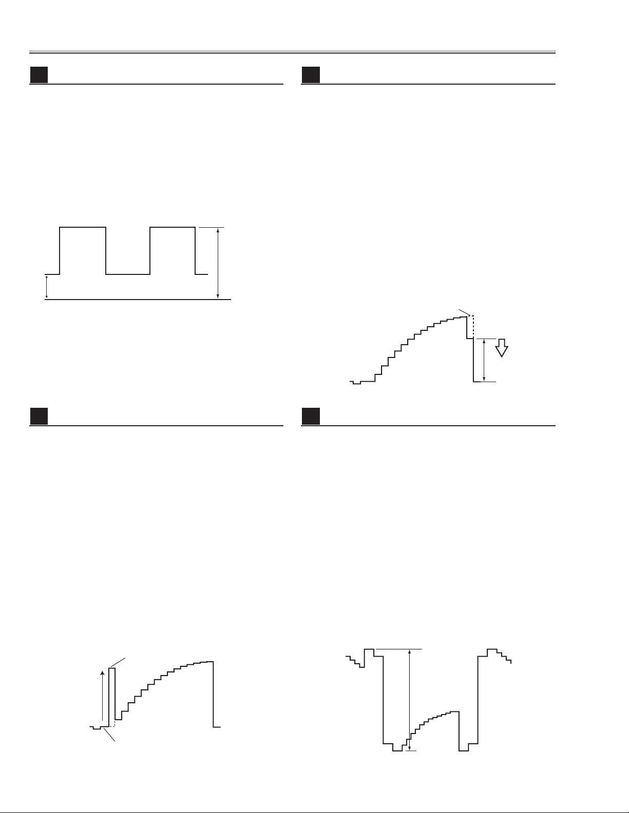
NRS adjustment
3
1. Receive the 16-step gray scale computer signal with
Computer 1 [Analog RGB] mode.
2. Enter the service mode.
3. Connect an oscilloscope to test point “TP531” (+)
and chassis ground (-).
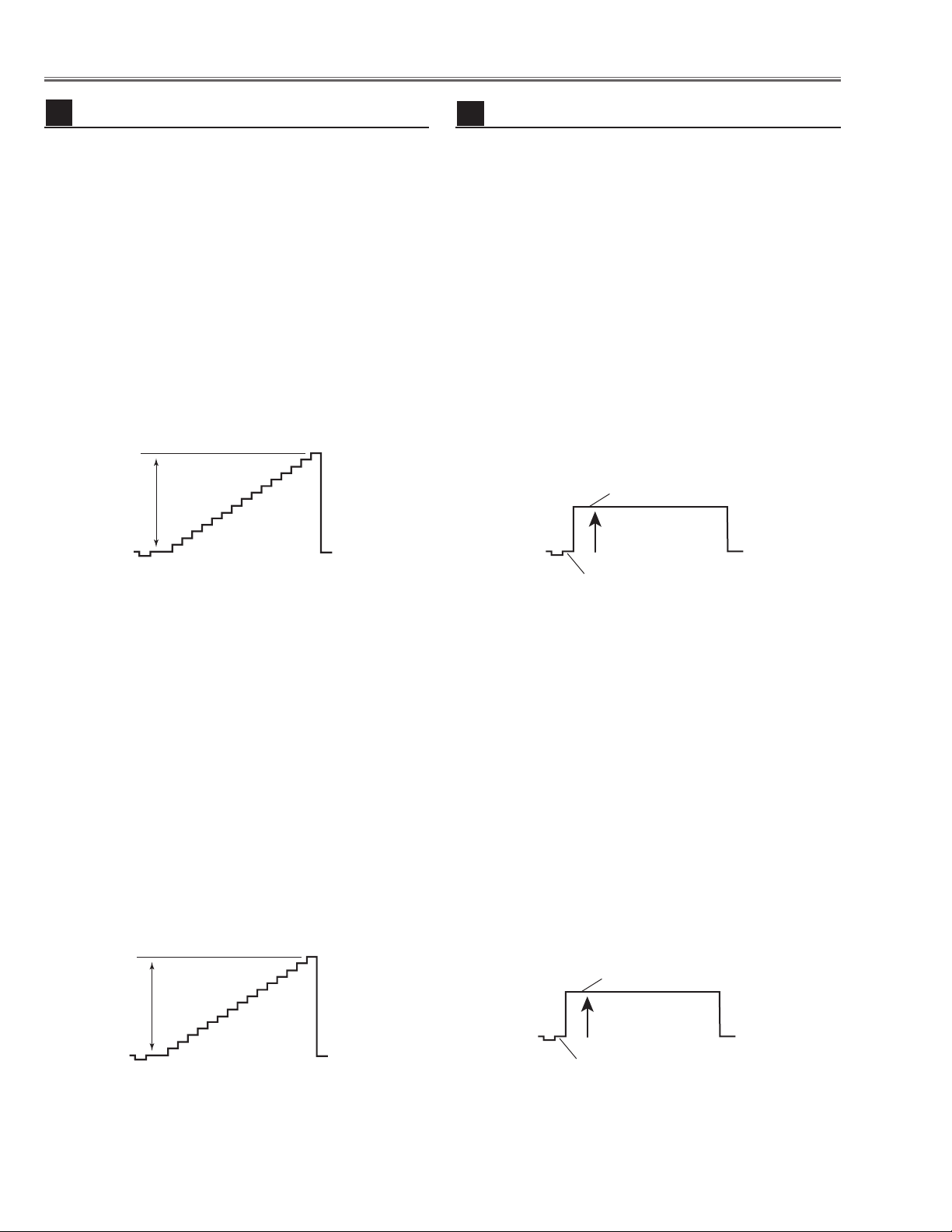
4. Select group no. “5”, Item no. “3” and adjust the
amplitude “a” to be 10.0 ±0.1V by changing the
Data value.
5. Connect an oscilloscope to test point “TP501”(+)
and chassis ground (-).
6. Select Item no. “4” and adjust the amplitude “a” to be
10.0 ±0.1V by changing the Data value.
7. Connect an oscilloscope to test point “TP561”(+)
and chassis ground (-).
8. Select Item no. “5” and adjust the amplitude “a” to be
10.0 ±0.1V by changing the Data value.
Black Level adjustment [PC]
6
1. Receive the 16-step gray scale computer signal with
Computer 1 [Analog RGB] mode.
2. Enter the service mode.
3. Connect an oscilloscope to test point “TP531”(+)
and chassis ground (-).
4. Select group no. “4”, Item no. “3” and adjust the white
level to be minimum amplitude by changing the Data
value.
5. Connect an oscilloscope to test point “TP501”(+)
and chassis ground (-).
6. Select Item no. “4” and adjust the white level to be
minimum amplitude by changing the Data value.
7. Connect an oscilloscope to test point “TP561”(+)
and chassis ground (-).
8. Select Item no. “5” and adjust the white level to be
minimum amplitude by changing the Data value.
Video Gain adjustment [PC]
5
(b)
(a)
GND
White Level
(a)
Black Lebel
black level
(a)
Pedestal Lebel
black level
-27-
Electrical Adjustments
1. Receive the 100%whole-white computer signal with
Computer 1 [Analog RGB] mode.
2. Enter the service mode.
3. Measure luminance on the screen with the luminance
meter. It is A for the reading of luminance meter.
4. Change the signal source to the 50%whole-white
computer signal with Computer 1 [Analog RGB]
mode.
5. Select group no. “4”, Item no. “6” and change the Data
value to make the reading of luminance meter to be A
x 23%
.
Luminance adjustment adjustment [PC]
7
1. Receive the 16-step gray scale composite video signal with Video mode.
2. Enter the service mode.
3. Connect a digital voltmeter to test point “TPVRB”(+)
and chassis ground (-).
4. Select group no. “5”, Item no. “17” and adjust the voltage to be 1.0 ±0.05Vdc by changing the Data value.
5. Connect a digital voltmeter to test point “TPGVRT (+)
and chassis ground (-).
6. Select Item no. “18” and adjust the voltage to be 2.5
±0.05Vdc by changing the Data value.
A/D Ref. Voltage adjustment [Video]
8
1. Receive the 16-step gray scale composite video signal with Video mode.
2. Enter the service mode.
3. Connect an oscilloscope to test point “TP13G”(+)
and chassis ground (-).
4. Select group no. “3”, Item no. “1” and adjust the amplitude “a” to be 1.35 ±0.1V by changing the Data value.
* This changes all the RGB amplitude at the same
time. Item no. “2” can be adjusted for G only.
5. Connect an oscilloscope to test point “TP13B”(+)
and chassis ground (-).
6. Select Item no. “3” and adjust the amplitude “a” to be
1.35 ±0.1V by changing the Data value.
7. Connect an oscilloscope to test point “TP13R”(+)
and chassis ground (-).
8. Select Item no. “4” and adjust the amplitude “a” to be
1.35 ±0.1V by changing the Data value.
A/D Input adjustment [Video]
9
1. Receive the 100%whole-Black composite video signal with Video mode.
2. Enter the service mode.
3. Connect an oscilloscope to test point “TP531” (+) and
chassis ground (-).
4. Select group no. “5”, Item no. “11” and adjust the
black level to be maximum amplitude by changing the
Data value.
5. Connect an oscilloscope to test point “TP501” (+) and
chassis ground (-).
6. Select Item no. “12” and adjust the black level to be
maximum amplitude by changing the Data value.
7. Connect an oscilloscope to test point “TP561” (+) and
chassis ground (-).
8. Select Item no. “13” and adjust the black level to be
maximum amplitude by changing the Data value.
Note: This adjustment should be done after A/D Input
adjustment [Video].
Pedestal adjustment [Video]
10
1. Receive the 16-step gray scale video composite signal with Video mode.
2. Enter the service mode.
3. Connect an oscilloscope to test point “TP531”(+)
and chassis ground (-).
4. Select group no. “4”, Item no. “3” and adjust the white
level to be minimum amplitude by changing the Data
value.
5. Connect an oscilloscope to test point “TP501”(+)
and chassis ground (-).
6. Select Item no. “4” and adjust the white level to be
minimum amplitude by changing the Data value.
7. Connect an oscilloscope to test point “TP561”(+)
and chassis ground (-).
8. Select Item no. “5” and adjust the white level to be
minimum amplitude by changing the Data value.
Video Gain adjustment [Video]
11
Black Lebel
Pedestal Lebel
(a)
White Level
(a)
-28-
Electrical Adjustments
[1080i-A/D INPUT ADJUSTMENT]
1. Receive the 16-step gray scale component signal
[1080i] with Video [Y/Pb,Pr/Cb,Cr] mode.
2. Enter the service mode.
3. Connect an oscilloscope to test point “TP13G”(+)
and chassis ground (-).
4. Select group no. “3”, Item no. “1” and adjust the amplitude “a” to be 1.35 ±0.1V by changing the Data value.
5. Connect an oscilloscope to test point “TP13B”(+)
and chassis ground (-).
6. Select Item no. “3” and adjust the amplitude “a” to be
1.35 ±0.1V by changing the Data value.
7. Connect an oscilloscope to test point “TP13R”(+)
and chassis ground (-).
8. Select Item no. “4” and adjust the amplitude “a” to be
1.35 ±0.1V by changing the Data value.
[480p-A/D INPUT ADJUSTMENT]
1. Receive the 16-step gray scale component signal
[480p] with Video [Y/Pb,Pr/Cb,Cr] mode.
2. Enter the service mode.
3. Connect an oscilloscope to test point “TP13G”(+)
and chassis ground (-).
4. Select group no. “3”, Item no. “1” and adjust the amplitude “a” to be 1.35 ±0.1V by changing the Data value.
5. Connect an oscilloscope to test point “TP13B”(+)
and chassis ground (-).
6. Select Item no. “3” and adjust the amplitude “a” to be
1.35 ±0.1V by changing the Data value.
7. Connect an oscilloscope to test point “TP13R”(+)
and chassis ground (-).
8. Select Item no. “4” and adjust the amplitude “a” to be
1.35 ±0.1V by changing the Data value.
A/D Input adjustment [Component]
12
[1080i-PEDESTAL ADJUSTMENT]
1. Receive the 100%whole-Black component signal
[1080i] with Video [Y/Pb,Pr/Cb,Cr] mode.
2. Enter the service mode.
2. Enter the service mode.
3. Connect an oscilloscope to test point “TP531”(+) and
chassis ground (-).
4. Select group no. “5”, Item no. “11” and adjust the black
level to be maximum amplitude by changing the Data
value.
5. Connect an oscilloscope to test point “TP501”(+) and
chassis ground (-).
6. Select Item no. “12” and adjust the black level to be
maximum amplitude by changing the Data value.
7. Connect an oscilloscope to test point “TP561”(+) and
chassis ground (-).
8. Select Item no. “13” and adjust the black level to be
maximum amplitude by changing the Data value.
[480p-PEDESTAL ADJUSTMENT]
1. Receive the 100%whole-Black component signal
[480p] with Video [Y/Pb,Pr/Cb,Cr] mode.
2. Enter the service mode.
3. Connect an oscilloscope to test point “TP531”(+) and
chassis ground (-).
4. Select group no. “5”, Item no. “11” and adjust the black
level to be maximum amplitude by changing the Data
value.
5. Connect an oscilloscope to test point “TP501”(+) and
chassis ground (-).
6. Select Item no. “12” and adjust the black level to be
maximum amplitude by changing the Data value.
7. Connect an oscilloscope to test point “TP561”(+) and
chassis ground (-).
8. Select Item no. “13” and adjust the black level to be
maximum amplitude by changing the Data value.
Note: These adjustments should be done after A/D
Input adjustment [Component].
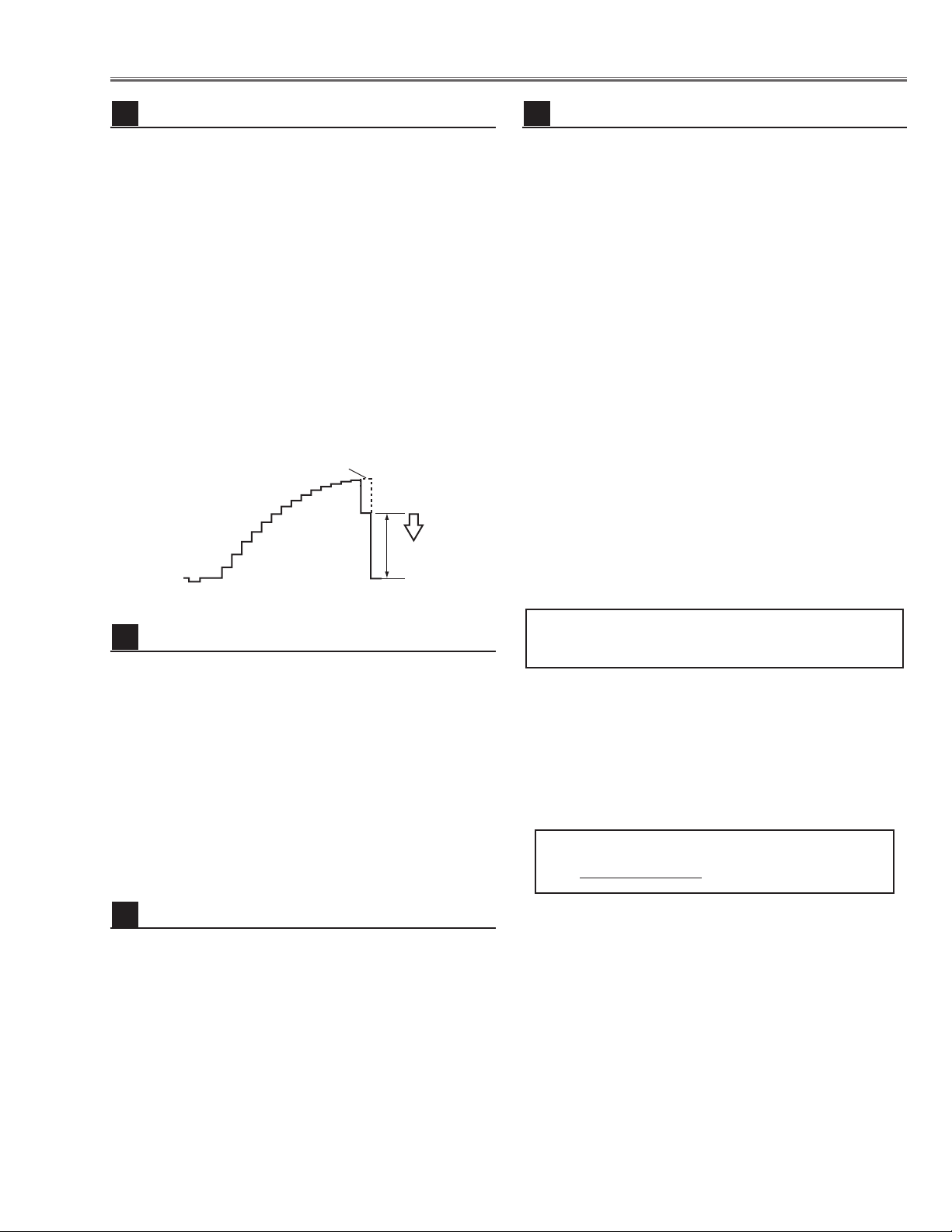
Pedestal adjustment [Component]
13
(a)
Black Lebel
(a)
Pedestal Lebel
Black Lebel
Pedestal Lebel
-29-
1. Receive the 1dot Black/White computer signal with
Computer 1 [Analog RGB] mode.
2. Enter the service mode.
3. Project only green light component to the screen.
4. Select group no. “5”, Item no. “9”and change Data
value to obtain the minimum flicker on the screen.
5. Project only blue light component to the screen.
6. Select Item no. “10 and change Data value to obtain
the minimum flicker on the screen.
7. Project only red light component to the screen.
8. Select Item no. “8” and change Data value to obtain
the minimum flicker on the screen.
Common Center adjustment
16
[PC WHITE BALANCE ADJUSTMENT]
1. Receive the 100%-whole white computer signal with
Computer 1 [Analog RGB] mode.
2. Enter the service mode.
3. Select group no. “4”, Item no. “7” (Red) or “8”(Blue),
and change Data values respectively to make a proper white balance.
[AV WHITE BALANCE ADJUSTMENT]
4. Receive the 100%-whole white video signal with
Video mode.
5. Enter the service mode.
6. Select group no. “4”, Item no. “7” (Red) or “8”(Blue),
and change Data values respectively to make a proper white balance.
White Balance adjustment
17
If you find the color shading at the some part of the
screen, it needs to take the color shading adjustment.
This adjustment should be performed by a computer
and it also requires a special software “Color Shading
Correction”. The software will be supplied separately
and can be ordered as follows;
COLOR SHADING CORRECTION SOFTWARE
Ser
vice Parts No. 645 051 2308
NOTE ON WHITE UNIFORMITY
ADJUSTMENT
1. Receive the 100%whole-white composite video signal
with Video mode.
2. Enter the service mode.
3. Measure luminance on the screen with the luminance
meter. It is A for the reading of luminance meter.
4. Change the signal source to the 50%whole-white
composite video signal with Video [Video] mode.
5. Select group no. “4”, Item no. “6” and change the Data
value to make the reading of luminance meter to be A
x 22%
.
Luminance adjustment [Video]
15
Electrical Adjustments
1. Receive the 16-step gray scale component signal
[1080i] with Video [Y/Pb,Pr/Cb,Cr] mode.
2. Enter the service mode.
3. Connect an oscilloscope to test point “TP531”(+)
and chassis ground (-).
4. Select group no. “4”, Item no. “3” and adjust the white
level to be minimum amplitude by changing the Data
value.
5. Connect an oscilloscope to test point “TP501”(+)
and chassis ground (-).
6. Select Item no. “4” and adjust the white level to be
minimum amplitude by changing the Data value.
7. Connect an oscilloscope to test point “TP561”(+)
and chassis ground (-).
8. Select Item no. “5” and adjust the white level to be
minimum amplitude by changing the Data value.
Video Gain adjustment [Component]
14
White Level
(a)
-30-
Electrical Adjustments
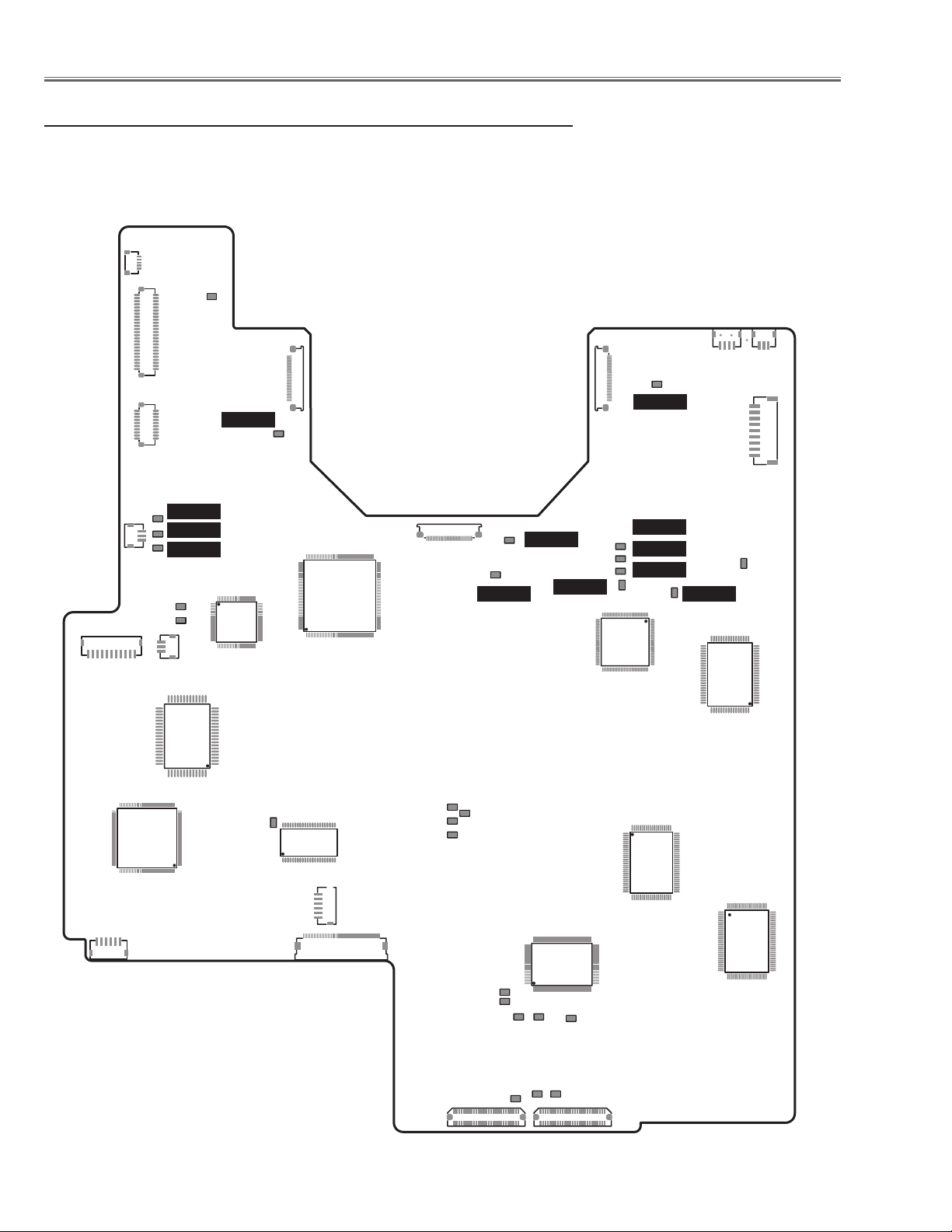
● MAIN BOARD
Test Points and Locations
K8L
TP2561
K8E
K8Q
K8J
TPDVS
TPDHS
IC801
K8F
TPFAN1
TPFAN2
TPFAN3
K8P
IC1801
TP561
IC9401
K25R
TP351
IC341
K8T
IC401
TPHD
TPGHS
K25G
TP531
TPVD
TPGVS
TP2531
TPGVRT
K25B
IC3201
IC6361
TP501
TP13B
TP13G
TP13R
K8M
TPVRB
K8R
K8G
TPHAFC
IC4101
K8S
K8V
TPHS
TPVS
K8W
TP21R
TP21G
TP20G
TP20R
IC1101
IC201
TP21B
TP20B
K8X
 Loading...