

Sanyo PLC-XR201,PLC-XR251 Service Manual
FILE NO.
SERVICE MANUAL
Multimedia Projector
Model No. PLC-XR201
PLC-XR251
U.S.A, Canada,
Europe, U.K, Asia
Original Version
PRODUCT CODE
PLC-XR201 PLC-XR251
1 122 485 20 (KR5AD) 1 122 487 20 (KS5AD)
1 122 486 20 (LR5AD) 1 122 488 20 (LS5AD)
1 122 486 22 (LR5CD) 1 122 488 22 (LS5CD)
Chassis No. KR5-XR20100
KS5-XR25100
Match the Chassis No. on the rating label of the projector
with the Chassis No. in the Service Manual.
If the Chassis No. in the Original Service Manual does
not match the projector's, additional Service Literature
is required. You must refer to "Notices" to the Original
Service Manual prior to the servicing.
REFERENCE NO. SM5111143-00

Contents
SERVICE MANUAL .......................................................1
Contents ........................................................................ 2
Safety Instructions ......................................................... 3
Safety Precautions ...................................................... 3
Product Safety Notice ................................................. 3
Service Personnel Warning ........................................3
Specifications ................................................................4
Circuit Protections .........................................................5
Thermal switch ........................................................... 5
Lamp cover switch ...................................................... 5
Fuse ............................................................................ 5
Warning temperature and power failure protection ..... 6
Maintenance .................................................................. 7
Cleaning the Filters ..................................................... 7
Resetting the Filter Counter ........................................ 7
Attaching the Lens Cap .............................................. 8
Cleaning the Projection Lens ...................................... 8
Lamp replacement ...................................................... 9
Resetting the Lamp Counter ..................................... 10
How to check Lamp Used Time ................................ 10
Security Function Notice.............................................. 11
Resetting procedure ................................................. 11
Mechanical Disassembly ............................................. 12
Optical Parts Disassembly ........................................... 17
Adjustments ................................................................. 24
Adjustments after Parts Replacement ...................... 24
Optical Adjustments ..................................................... 25
Contrast adjustment.................................................. 26
Condenser Out lens adjustment ............................... 27
Relay lens-Out adjustment ....................................... 28
Electrical Adjustments ................................................. 29
Service Adjustment Menu Operation ........................ 29
Memory IC (IC1371) Replacement ........................... 29
Circuit Adjustments ................................................... 30
Test Points and Locations ......................................... 35
Service Adjustment Data Table ................................. 36
Chassis Block Diagrams .............................................. 54
Chassis over view ..................................................... 54
System control .......................................................... 55
Lamp control ............................................................. 56
Audio circuit .............................................................. 57
Power supply & protection circuit .............................. 58
Fan control circuit ..................................................... 59
IIC bus control circuit ................................................ 60
Troubleshooting ...........................................................61
Indicators and Projector Condition ........................... 61
No Power .................................................................. 62
No Picture ................................................................. 63
No Sound .................................................................. 64
Control Port Functions ................................................. 65
Scaler I/O Port Functions (PW190) .......................... 65
IC Block Diagrams ....................................................... 66
Electrical Parts List ...................................................... 71
Electrical Parts Location ........................................... 72
Electrical Parts List ................................................... 73
Mechanical Parts List ..................................................88
Cabinet Parts Location ............................................. 88
Optical Parts Location .............................................. 89
Mechanical Parts List ............................................... 95
Diagrams & Drawings ..................................................A1
Parts description and reading in schematic diagram ...A2
Schematic Diagrams ...................................................A3
Printed Wiring Board Diagrams .................................A11
Pin description of diode, transistor and IC .................A15
Note on Soldering ......................................................A16
-2-
Safety Instructions
Safety Precautions
WARNING:
The chassis of this projector is isolated (COLD) from AC line by using the converter transformer. Primary side
of the converter and lamp power supply unit circuit is connected to the AC line and it is hot, which hot circuit is
identified with the line ( ) in the schematic diagram. For continued product safety and protection of personnel injury, servicing should be made with qualified personnel.
The following precautions must be observed.
1: An isolation transformer should be connected in
the power line between the projector and the AC line
before any service is performed on the projector.
2: Comply with all caution and safety-related notes
provided on the cabinet back, cabinet bottom, inside
the cabinet or on the chassis.
3: When replacing a chassis in the cabinet, always
be certain that all the protective devices are
installed properly, such as, control knobs, adjustment covers or shields, barriers, etc.
DO NOT OPERATE THIS PROJECTOR WITHOUT
THE PROTECTIVE SHIELD IN POSITION AND PR
OPERLY SECURED.
4: Before replacing the cabinet cover, thoroughly
inspect the inside of the cabinet to see that no stray
parts or tools have been left inside.
Before returning any projector to the customer, the
service personnel must be sure it is completely safe
to operate without danger of electric shock.
Product Safety Notice
Product safety should be considered when a component replacement is made in any area of the projector.
Components indicated by mark ! in the parts list and the schematic diagram designate components in which
safety can be of special significance. It is, therefore, particularly recommended that the replacement of there
parts must be made by exactly the same parts.
Service Personnel Warning
Eye damage may result from directly viewing the light produced by the Lamp used in this equipment. Always
turn off Lamp before opening cover. The Ultraviolet radiation eye protection required during this servicing.
Never turn the power on without the lamp to avoid electric-shock or damage of the devices since the stabilizer
generates high voltages (15kV - 25kV) at its starts.
Since the lamp is very high temperature during units operation replacement of the lamp should be done at least
45 minutes after the power has been turned off, to allow the lamp cool-off.
-3-

Specifications
Mechanical Information
Projector Type Multi-media Projector
Dimensions (W x H x D) 13.13" x 3.35" x 9.72" (333.5mm x 85.2mm x 247.0mm) (Not including protrusions)
Net Weight 5.5 lbs (2.5 kg)
Foot Adjustment 0˚ to 10˚
Panel Resolution
LCD Panel System 0.55" TFT Active Matrix type, 3 panels
Panel Resolution 1,024 x 768 dots
Number of Pixels 2,359,296 (1,024 x 768 x 3 panels)
Signal Compatibility
Color System
High Definition TV Signal 480i, 480p, 575i, 575p, 720p, 1035i, and 1080i
Scanning Frequency H-sync. 15 kHz–100 kHz, V-sync. 50–100 Hz
Optical Information
Projection Image Size (Diagonal) Adjustable from 40” to 300”
Throw Distance 4.3' - 38.7' (1.30m - 11.80m)
Projection Lens F 2.0 ~ 2.15 lens with f 18.38 mm ~ 22.06 mm with manual zoom and focusF 2.0 ~ 2.15 lens with f 18.38 mm ~ 22.06 mm with manual zoom and focus
Projection Lamp 220 W
Interface
Video Input Jack RCA Type x 1
Audio Input Jack Mini Jack (stereo) x 1
Computer In 1/ S-video In Mini D-sub 15 pin x 1
/ Component Input Terminal
Computer In 2 / Monitor Out Terminal Mini D-sub 15 pin x 1
Control port D-sub 9 pin x 1
Audio Output Jack Mini Jack (stereo) x 1 (variable)
LAN Connection Terminal 100 Base-TX (100Mbps)/10 Base-T (10Mbps), RJ45
Audio
Internal Audio Amp 1.0 W RMS
Built-in Speaker 1 speaker, ø1.1" (28mm)
Power
Voltage and Power Consumption PLC-XR201:
AC 100–120 V (3.3A Max. Ampere), 50/60 Hz (The U.S.A and Canada)
AC 200–240 V (1.8A Max. Ampere), 50/60 Hz (Continental Europe and The U.K.)
PLC-XR251:
AC 100–120 V (3.5A Max. Ampere), 50/60 Hz (The U.S.A and Canada)
AC 200–240 V (1.9A Max. Ampere), 50/60 Hz (Continental Europe and The U.K.)
Operating Environment
Operating Temperature 41˚F–95˚F (5 ˚C–35 ˚C)
Storage Temperature 14˚F–140˚F (-10˚C–60 ˚C)
Remote Control
Battery AAA or LR03 1.5V ALKALINE TYPE x 2Battery AAA or LR03 1.5V ALKALINE TYPE x 2
Operating Range 16.4' (5 m)/±30˚Operating Range 16.4' (5 m)/±30˚
Dimensions 2.0" (W) x 0.7" (H) x 4.3" (D) (52 mm x 18 mm x 110 mm)Dimensions 2.0" (W) x 0.7" (H) x 4.3" (D) (52 mm x 18 mm x 110 mm)
Net Weight 2.37 oz (67 g) (including batteries)Net Weight 2.37 oz (67 g) (including batteries)
PAL, SECAM, NTSC, NTSC4.43, PAL-M, and PAL-N
●The specifications are subject to change without notice.
●LCD panels are manufactured to the highest possible standards. Even though 99.99% of the pixels are effective, a tiny
fraction of the pixels (0.01% or less) may be ineffective by the characteristics of the LCD panels.
This symbol on the nameplate means the product is Listed by Underwriters
Laboratories Inc. It is designed and manufactured to meet rigid U.L. safety standards against risk of fire, casualty and electrical hazards.
-4-
Circuit Protections
This projector provides the following circuit protections to operate in safety. If the abnormality occurs inside the projector, it will automatically turn off by operating one of the following protection circuits.
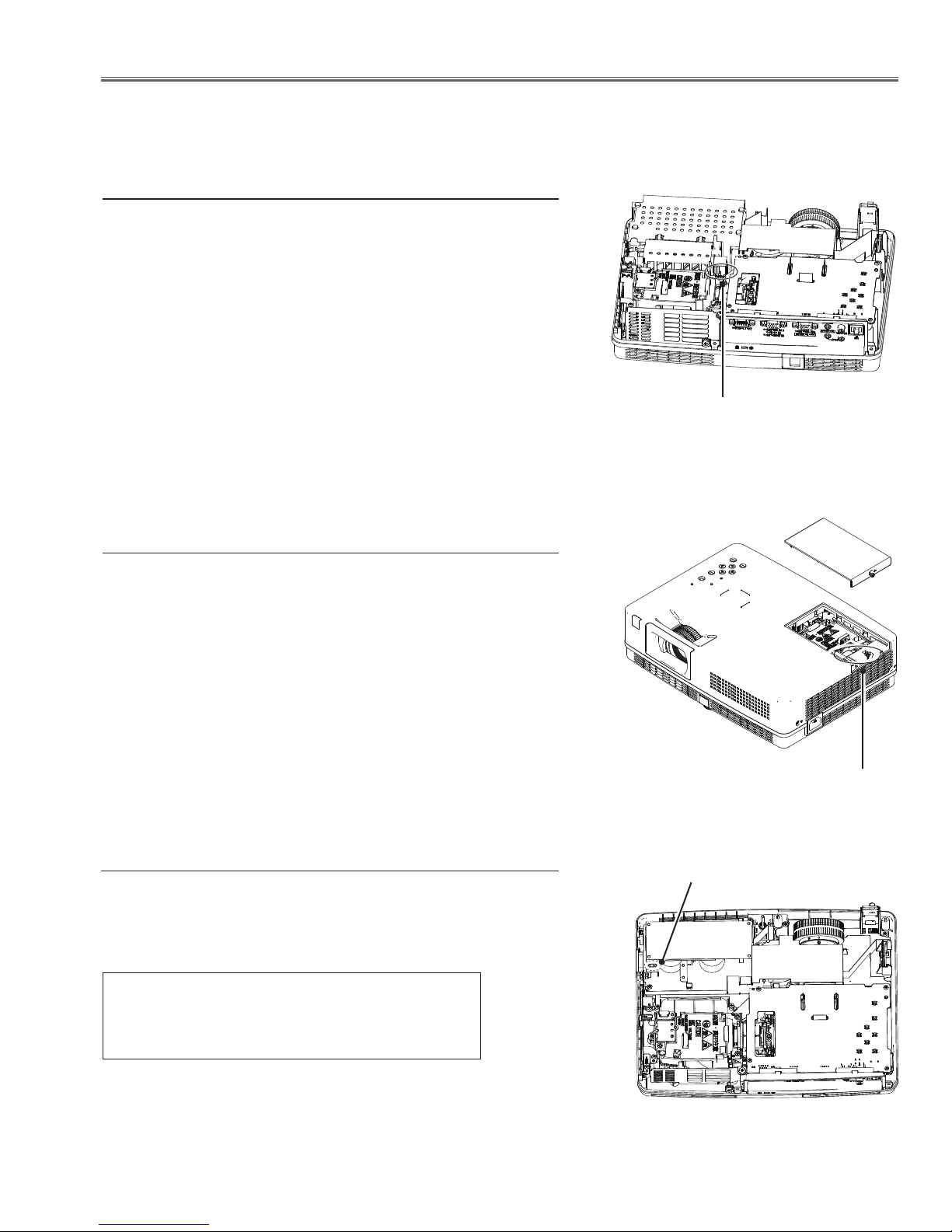
Thermal switch
There is the thermal switch (SW601) inside of the projector to detect
the internal temperature rising abnormally. When the internal temperature reaches near 85˚C, the thermal switch opens to stop the
operation of the power supply circuit.
The thermal switch can be reset itself automatically when the internal temperature becomes normal.
When the internal temperature reaches near 50˚C, the thermal
switch returns automatically.
Thermal switch (SW601)
Lamp cover switch
The lamp cover switch (SW902) cuts off the drive signal to the lamp
circuit when the lamp cover is removed or not closed completely.
After opening the lamp cover for replacing the lamp ass’y, place the
lamp cover correctly otherwise the projector can not turn on.
Fuse
A fuse is located inside of the projector. When the POWER indicator
is not lighting, the fuse may be opened. Check the fuse as following
steps.
The fuse should be used with the following type;
Lamp cover switch
(SW902)
Fuse
Fuse Part No.: 323 021 7804
TYPE T6.3AH 250V FUSE
LITTLE FUSE INC. TYPE 21506.3
How to replace the fuse
1. The fuse is placed on the power board. Remove the cabinet top ,
main board, optical engine and the fan(FN001).
2. Take the fuse off, and replace the new one with the specified type.
-5-
Circuit Protections
Warning temperature and power failure protection
The projector will be automatically turned off when the internal temperature of the projector is abnormally high, or the
cooling fans stop spinning, or the power supplies in the projector are failed.
- If the WARNING indicator is flashing, it may detect the abnormal temperature inside the projector. Check the following possible causes and wait until the POWER indicator stops flashing, and then try to turn on the projector.
- If the WARNING indicator lights red, it may defect the cooling fans or power supply circuits. Check fans operation
and power supply lines referring to the chapter “Power supply & protection circuit” in the Chassis Block Diagram
section.
Possible causes
- Air filters are clogged with dust particles. Remove dust from the air filters by following instructions in the “Air filter
care and cleaning” below.
- Ventilation slots of the projector are blocked. In such an event, reposition the projector so that ventilation slots are
not obstructed.
- Check if projector is used at higher temperature place (Normal operating temperature is 5 to 35 ˚C or 41 to 95˚F)
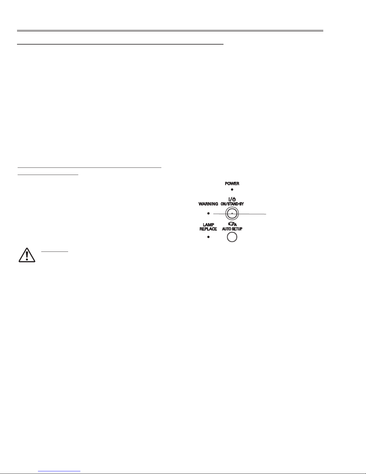
The projector is shut down and the WARNING
indicator lights red.
When the projector detects an abnormal condition, it is
automatically shut down to protect the inside of the projector
and the WARNING indicator lights red. In this case, unplug
the AC power cord and reconnect it, and then turn the
projector on once again to verify operation. If the projector
cannot be turned on and the WARNING indicator still lights
red, unplug the AC power cord and contact the service
station.
CAUTION
DO NOT LEAVE THE PROJECTOR WITH THE
AC POWER CORD CONNECTED UNDER AN
ABNORMAL CONDITION. IT MAY RESULT IN
FIRE OR ELECTRIC SHOCK.
Top Control
WARNING emi t a
red light
-6-
Maintenance
Cleaning the Filters
Filter prevents dust from accumulating on the optical elements inside the projector. Should the filters become
clogged with dust particles, it will reduce cooling fans’ effectiveness and may result in internal heat buildup
and adversely affect the life of the projector. If a “Filter warning” icon appears on the screen, clean the filters
immediately. Clean the filters by following the steps below.
Turn off the projector, and unplug the AC power cord
1
from the AC outlet.
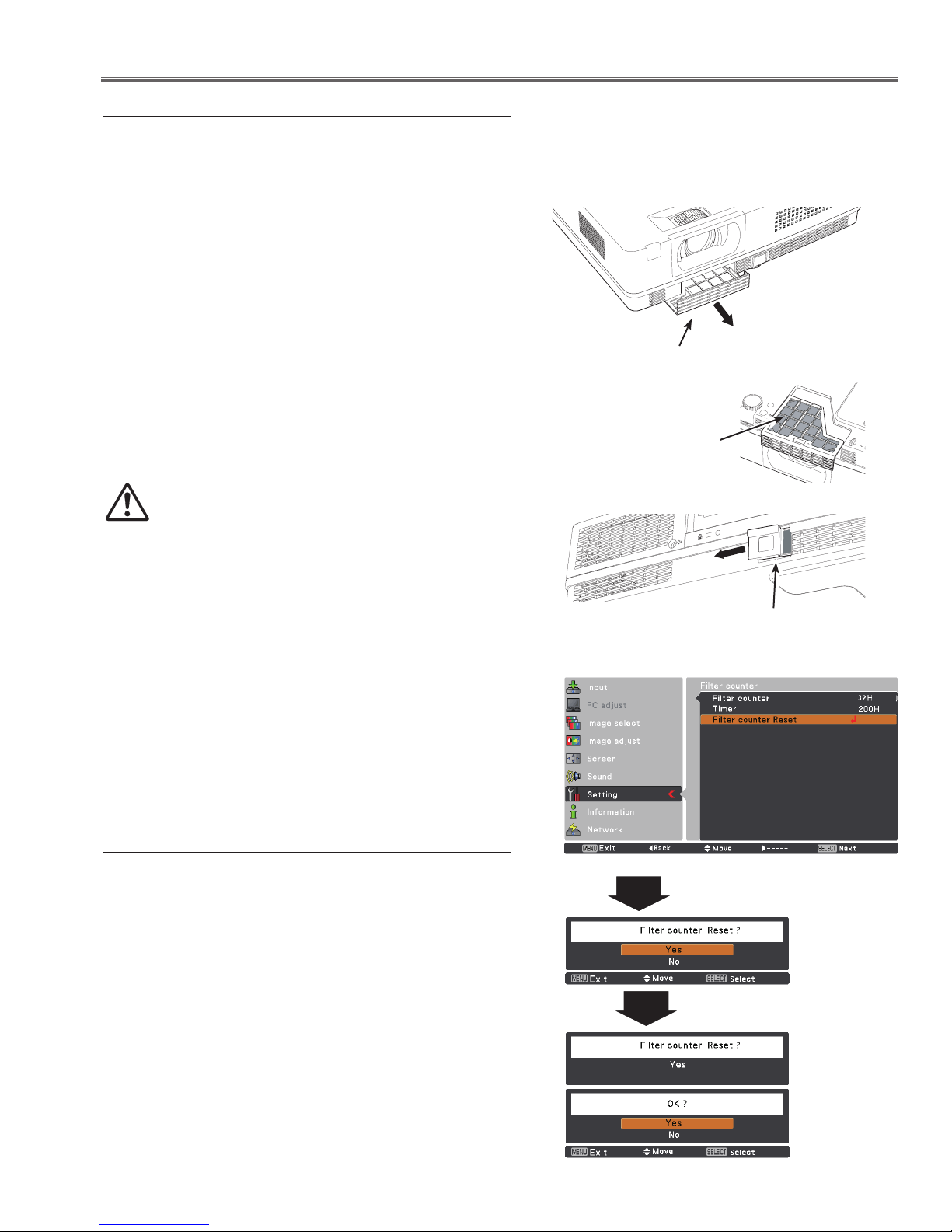
Remove the front air filter by pulling the latch
2
horizontally.
Remove the back air filter by pulling the latch
horizontally and then remove it leftward.
Clean the air filters with a brush or rinse them softly.
3
Pull horizontally and remove.
Air filter (front)
When cleaning the air filters by rinsing, dry it well.
4
Replace the air filters properly. Make sure that the air
filters are fully inserted.
CAUTION
Do not operate the projector with the filters
removed. Dust may accumulate on the optical
elements degrading picture quality.
Do not put anything into the air vents. Doing so
may result in malfunction of the projector.
RECOMMENDATION
We recommend avoiding dusty/smoky environments
when you operate the projector. Usage in these
environments may cause poor image quality.
When using the projector under dusty or smoky conditions,
dust may accumulate on a lens, LCD panels, or optical
elements inside the projector degrading the quality of a
projected image. When the symptoms above are noticed,
contact your authorized dealer or service station for proper
cleaning.
Resetting the Filter Counter
Be sure to reset the Filter counter after cleaning or replacing
the filters.
4 Note:
Please be sure to
fit this edge when
inserting this filter.
Air filter (back)
Pull horizontally and then remove it leftward.
Filter counter
Press the MENU button to display the On-Screen
1
Menu. Use the Point buttons to select Setting and
then press the Point or SELECT button.
Use the Point buttons to select Filter counter and
2
then press the Point or the SELECT button. Use the
Point buttons to select Filter counter reset and then
press the SELECT button. Filter counter Reset?
appears. Select Yes to continue.
Another confirmation dialog box appears, select Yes to
3
reset the Filter counter.
Filter counter
Reset? appears.
Select Yes, then
another confirmation
box appears.
Select Yes again
to reset the Filter
counter.
-7-
Maintenance
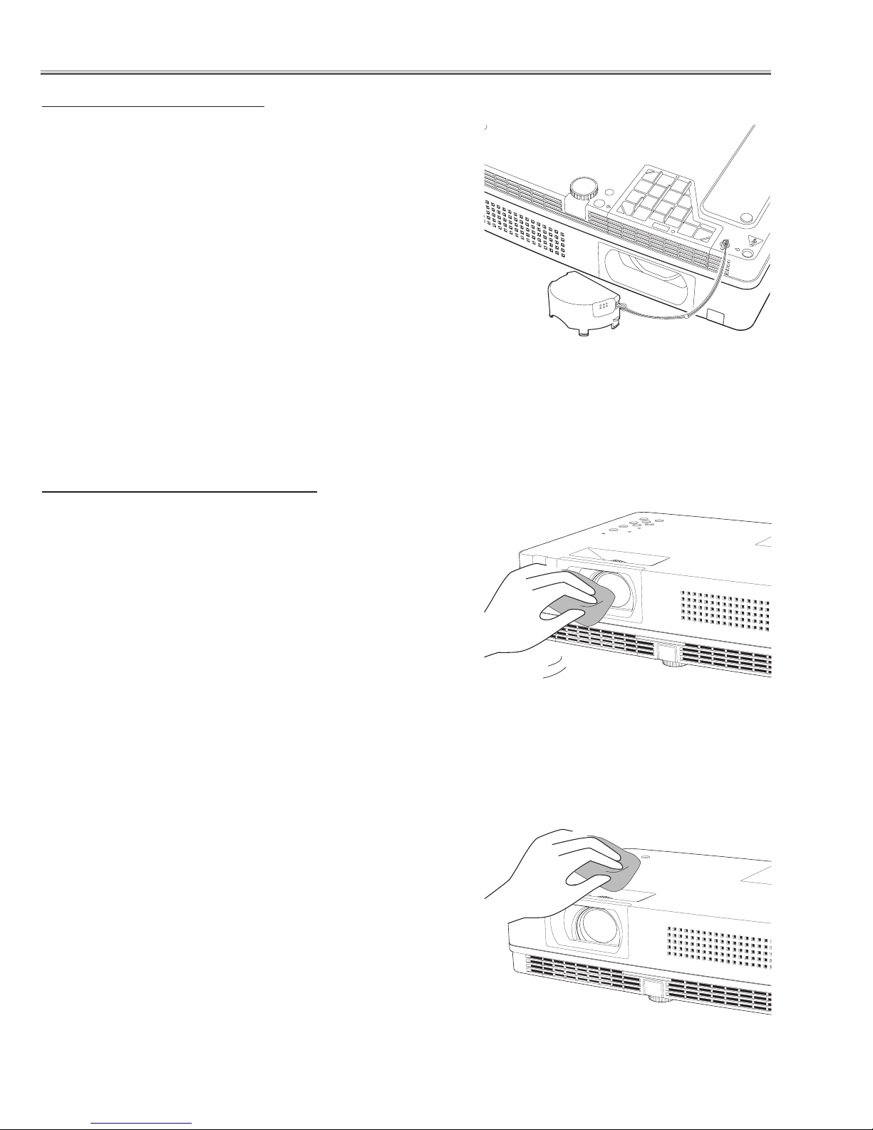
Attaching the Lens Cap
When moving this projector or while not using it over an
extended period of time, replace the lens cap.
Attach the lens cap according to the following procedures.
Thread the string through the hole on the lens cap and
1
then tie a knot in the string to secure it in place.
To pass the other end of the string into the hole on the
2
bottom of the projector and pull at it.
Cleaning the Projection Lens
Unplug the AC power cord before cleaning.
Gently wipe the projection lens with a cleaning cloth that
contains a small amount of non-abrasive camera lens
cleaner, or use a lens cleaning paper or commercially
available air blower to clean the lens.
Avoid using an excessive amount of cleaner. Abrasive
cleaners, solvents, or other harsh chemicals might scratch
the surface of the lens.
Cleaning the Projector Cabinet
Unplug the AC power cord before cleaning.
Gently wipe the projector body with a soft dry cleaning cloth.
When the cabinet is heavily soiled, use a small amount of
mild detergent and finish with a soft dry cleaning cloth. Avoid
using an excessive amount of cleaner. Abrasive cleaners,
solvents, or other harsh chemicals might scratch the surface
of the cabinet.
When the projector is not in use, put the projector in an
ap propria te ca rrying ca se to prot ect it fro m dust and
scratches.
-8-
Lamp Replacement
Lamp replacement
WARNING:
- For continued safety, replace with a lamp assembly of the same type.
- Allow the projector to cool for at least 45 minutes before you open the
lamp cover. The inside of the projector can become very hot.
- Do not drop the lamp module or touch the glass bulb! The glass can
shatter and cause injury.
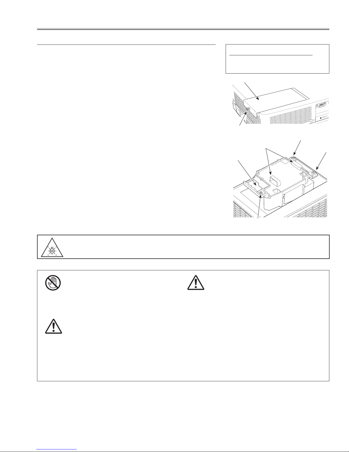
Follow these steps to replace the lamp.
Unplug the AC power cord. Let the projector cool for at
1
least 45 minutes.
Loosen the screw and open the lamp cover.
2
Loosen the three (3) screws that secure the lamp. Lift
3
the lamp out of the projector by using the handles.
Replace the lamp with a new one and secure the three
4
(3) screws. Make sure that the lamp is set properly.
Close the lamp cover and secure the screw.
Connect the AC power cord to the projector and turn
5
on the projector.
Reset the Lamp Replace Counter.
6
Refer to the next page for details.
ORDER REPLACEMENT LAMP
Type No. POA-LMP132
Service Parts No. 610 345 2456
Lamp Cover
Screw
Screw
Handles
Lamp
Screw
Screw
WARNING : TURN OFF THE UV LAMP BEFORE OPENING THE LAMP COVER.
USE UV RADIATION EYE AND SKIN PROTECTION DURING SERVICING.
CAUTION
Allow a projector to cool for at least 45 minutes
before you open the Lamp Cover. The inside of the
projector can become very hot.
For continued safety, replace with a lamp of the same
type. Do not drop a lamp or touch a glass bulb! The
glass can shatter and may cause injury.
CAUTION
CAUTION
When replacing the lamp because it has stopped illuminating, there is a possibility that the lamp may be
broken.
If replacing the lamp of a projector which has been installed on the ceiling, you should always assume that the
lamp is broken, and you should stand to the side of the lamp cover, not underneath it. Remove the lamp cover
gently. Small pieces of glass may fall out when the lamp cover is opened. If pieces of glass get into your eyes
or mouth, seek medical advice immediately.
-9-
Lamp Replacement
Counter
Projector 500H
Lamp
High/Normal 200 H
Eco 300 H
Corresponding value 600 H
Recommendation
Should the air filter become clogged with dust particles, it will reduce the cooling fan’s effectiveness and may result in
internal heat build up and short lamp life. We recommend cleaning the air filter after the projection lamp is replaced.
Refer to “Air Filter Cleaning”.
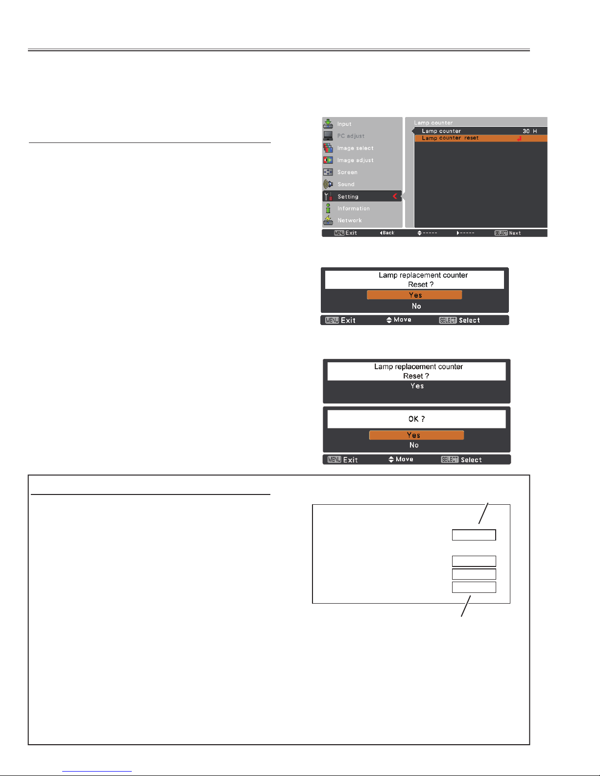
Lamp counter reset
Resetting the Lamp Counter
Be sure to reset the Lamp replacement counter after the
lamp is replaced.
Press the Point ▲▼ buttons to choose the Lamp counter
function and then press the Point
access the submenu items.
Lamp counter................This item shows the total
accumulated time of the lamp
usage.
Lamp counter reset.......Press the the SELECT button
to choose Lamp counter reset.
Select Yes in the confirmation
box if you want to reset the lamp
counter, and then choose Yes in
the second confirmation box to
reset lamp counter.
or the SELECT button to
How to check Lamp Used Time
The LAMP REPLACE indicator will light yellow when
the total lamp used time (Corresponding value) reaches
3,000 hours. This is to indicate that lamp replacement is
required.
The total lamp used time is calculated by using the below expression,
Total lamp used time = Teco + Thigh/normal x 1.5
Teco: used time in the Eco mode
Thigh/normal : used time in the Normal mode and
High mode.
You can check the lamp used time following to the below
procedure.
1 Press and hold the ON/STAND-BY button on the pro-
jector for more than 20 seconds.
2 The projector used time and lamp used time will be
displayed on the screen briefly as follows.
Projector used time
Total lamp used time
-10-
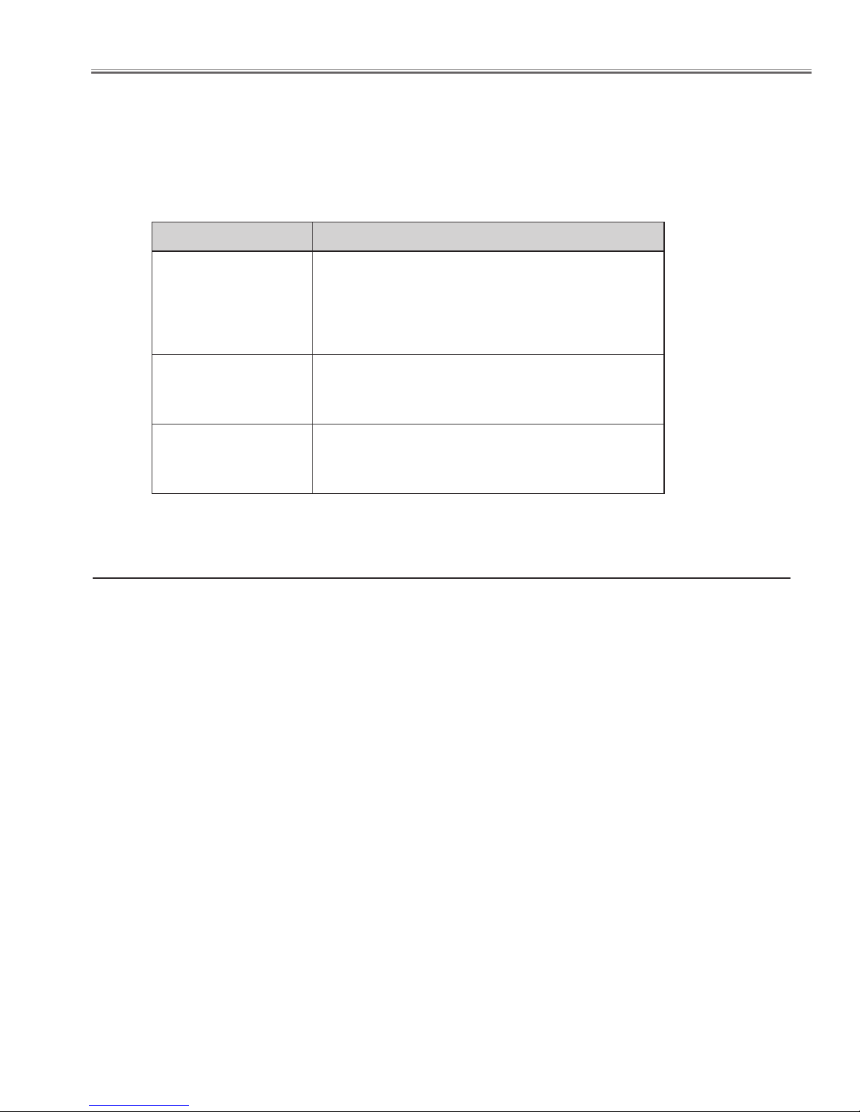
Security Function Notice
This projector provides security functions such as "Key lock", "PIN code lock" and "Logo PIN code lock". When the projector has set these security function on, you are required to enter correct PIN code to use the projector. If you do not
know the correct PIN code to the projector, the projector can no longer be operated or started. In this case, you must
reset those function first according to the resetting procedure described below and then check up on the projector.
Function Description
Locks operation of the top control or the remote control.
Key lock
PIN code lock
Logo PIN code lock
If the Key lock is enabled with top control lock, the projector can no longer be started.
Initial setting: Key lock function is disabled
Prevents the projector from being operated by an unauthorized person.
Initial code: “1234”
Prevents an unauthorized person for changing the
start-up logo on the screen.
Initial code: “4321”
Resetting procedure
1. Disconnect the AC power cord from the AC outlet.
2. As pressing the SELECT button, connect the AC power cord into an AC outlet again.
3. Keep pressing the SELECT button and then press the ON/STAND-BY button.
4. Release the ON/STAND-BY button first and then release the SELECT button.
- The PIN code lock and Logo PIN code lock will be reset as the initial PIN code at the factory and
the key lock function is disabled.
Please refer to the owner's manual for further information of the security functions.
-11-
Mechanical Disassembly
Mechanical disassembly should be made following procedures in numerical order.
Following steps show the basic procedures, therefore unnecessary step may
be ignored.
Caution:
The parts and screws should be placed exactly the same position as the original
otherwise it may cause loss of performance and product safety.
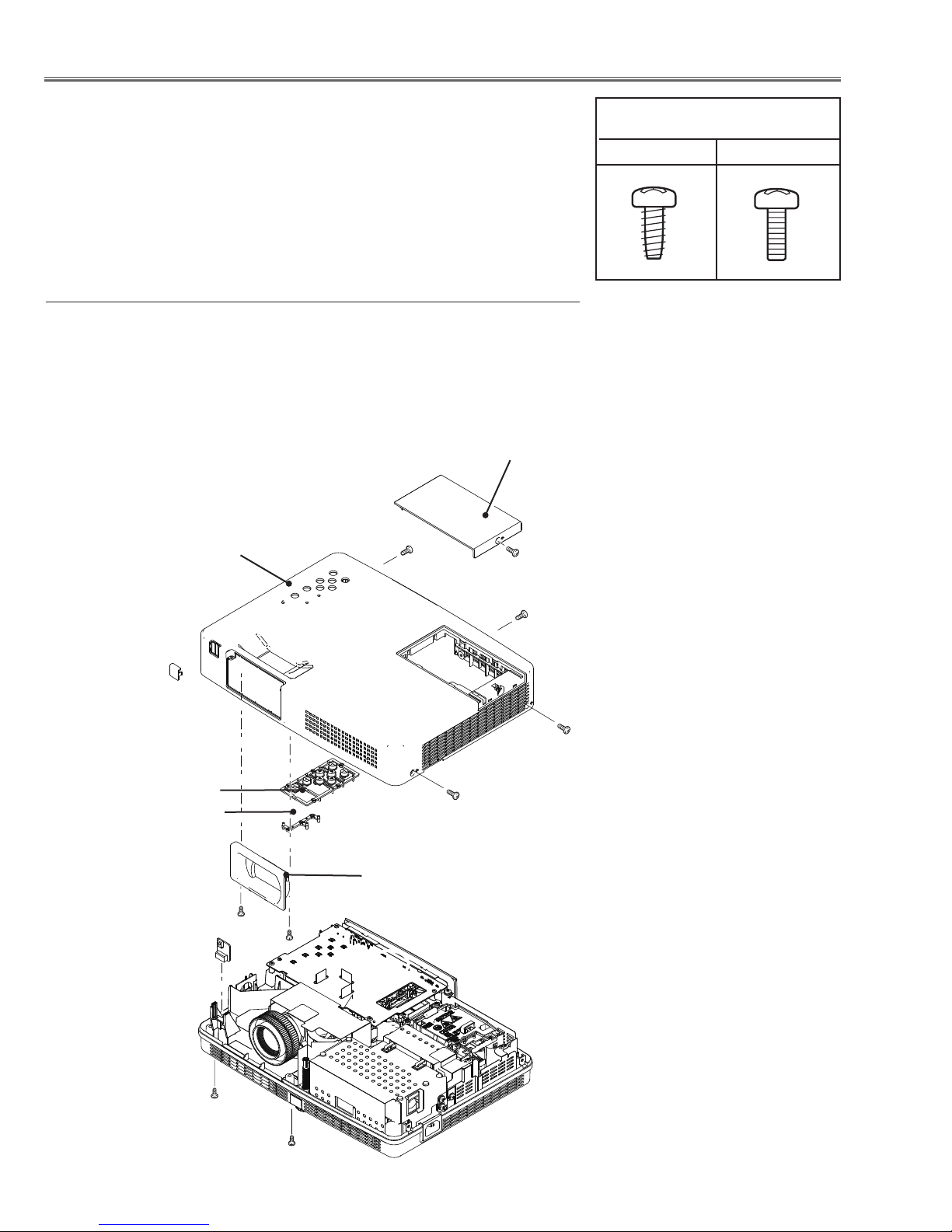
z Cabinet Top, R/C Board removal
1. Loose screw A (M3x8 ) to remove the Lamp Cover.
2. Remove 4 screws B (M3x8 ) and 2 screws C(T3x10) to remove the Cabinet top.
3. Remove the Control Buttons and Dec Inlay LED.
4. Remove 2 screws D (T3x8) to remove the Dec Ring.
5. Remove the R/C Board.
Lamp Cover
Cabinet top
B
A (M3x8)
Screws Expression
(Type Diameter x Length) mm
T type M Type
Dec Inlay RC
Control Buttons
Dec Inlay LED
R/C Board
B
B
B (M3x8)x4
Dec Ring
D (T3X8)x2
D
C (T3X10)x2
C
Fig.1
-12-
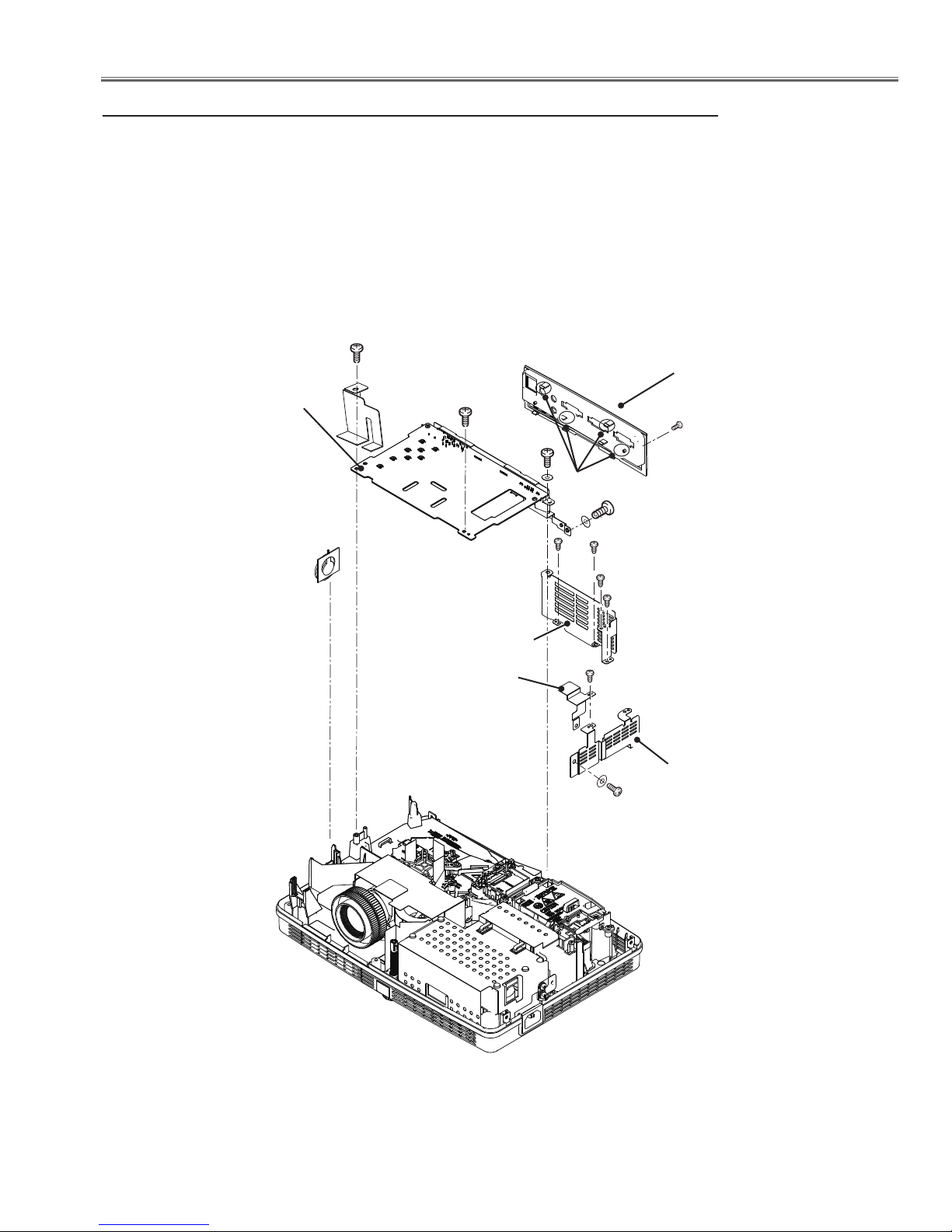
Mechanical Disassembly
x Main Board, AV Panel and Speaker (SP901) removal
1. Remove 5 screws A (M3x8) and 3 screws B(M4x6) to remove the Right connect shield,
Lamp back shield and Right shield.
2. Remove 2 screws C (T3x8) to remove the Main Board.
3. Release the hooks and screw D (M2x4) to remove the AV Panel.
4. Remove the Speaker (SP901).
C (T3x8)x2
AV Panel
Main Board
C
D (M2x4)
B
Hooks
B
Speaker (SP901)
Lamp back shield
Right connect shield
A
A
A
A
A (M3x8)x5
Right shield
B (M4x6)x3
Fig.2
-13-
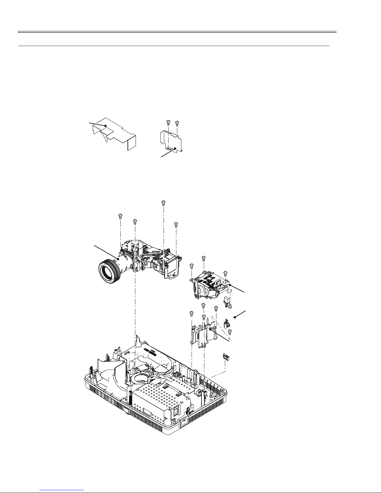
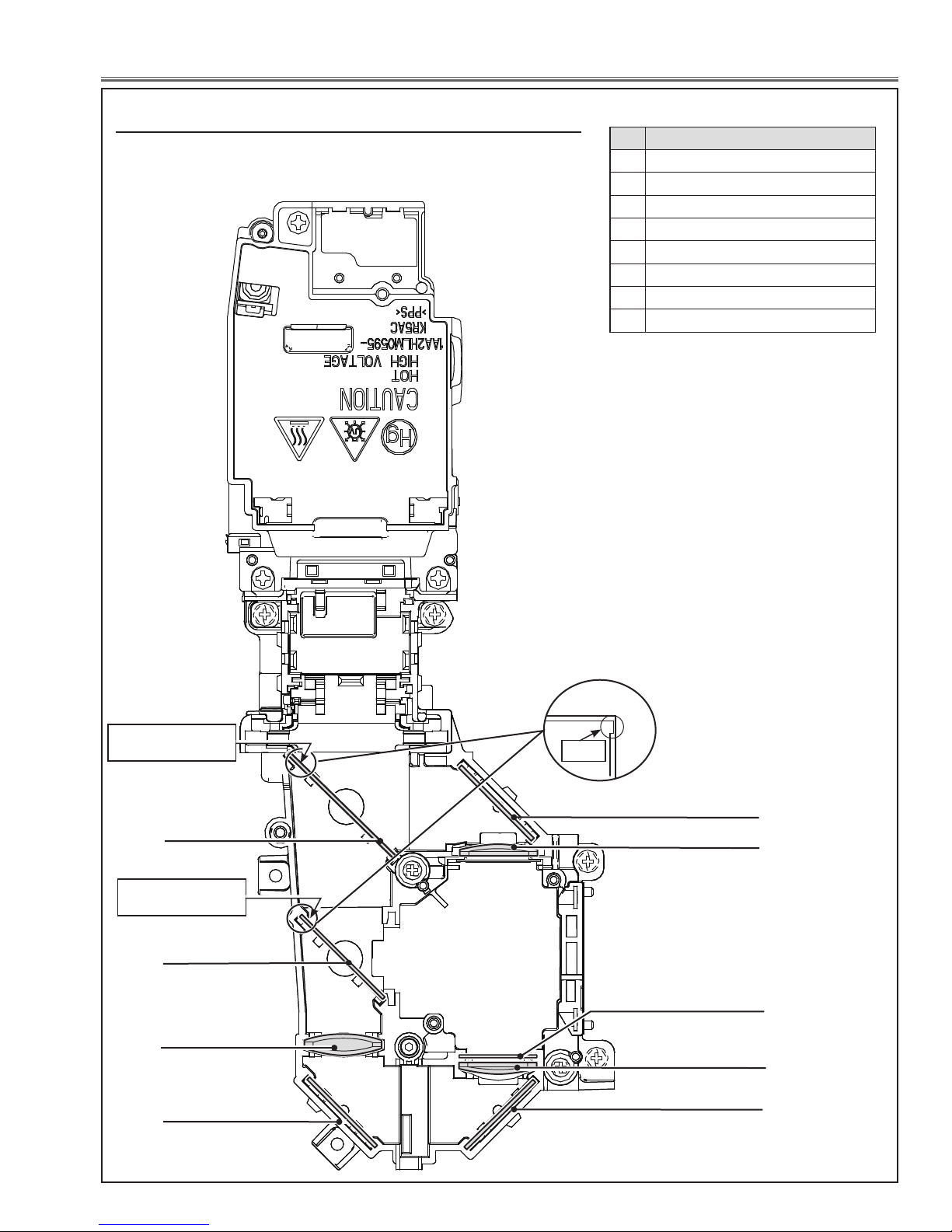
Mechanical Disassembly
c Optical Unit, Lamp A'ssy and SW902 removal
1. Remove the Lens spacer sheet-top. Remove 2 screws A(M3x8) to remove the
Optical back shield.
2. Remove 3 screws B(M3x7) to remove the Lamp A'ssy. Remove 4 screws
C(T3x10) to remove the Optical Unit, Remove 4 screws D(T3x8) and 2 screws
E(T3x8) to remove the Lamp holder and Ballast socket.
3. Remove the lamp cover switch(SW902).
Lens spacer
sheet-top
Optical Unit
Optical back shield
C (T3x10)X4
A (M3x8)X2
C
A
C
C
B
B
B (M3x7)x3
Lamp Ass'y
D (T3x8)x4
-14-
D
D
E
D
Lamp holder
Ballast socket
E(T3x8)x2
SW902
Fig.3
Mechanical Disassembly
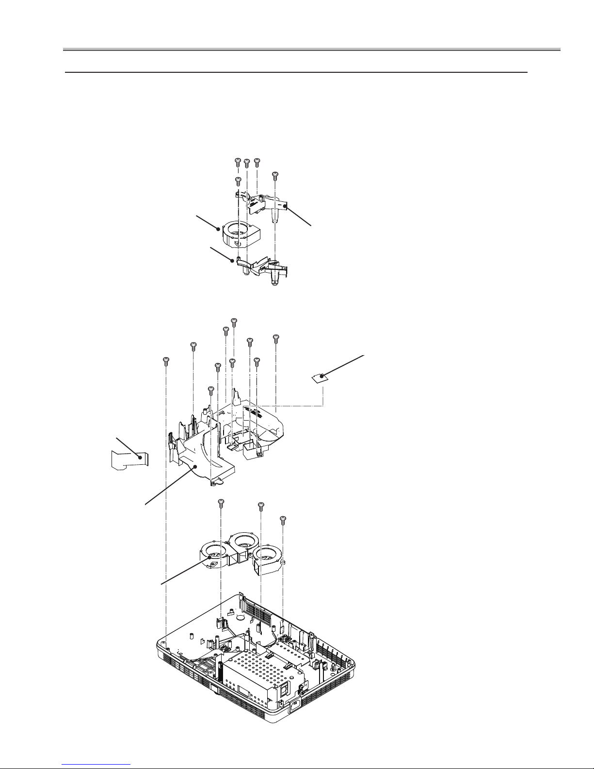
v Mounting Duct and fans(FN001, FN003, FN004, FN005) removal
1. Remove the Lens spacer sheet-left, remove 3 screws A(T3x8) and 2
screw B(T3x12) to remove the Lamp in fan duct top and bottom.
2. Remove 7 screws C(T3X8) and 3 screws D(T3x12) to remove the Mounting
duct top.
3. Remove 3 screws E(T3x12) to remove the fans(FN003, FN004 and FN005).
A
B
B(T3x12)x2
FN001
A
A (T3x8)x3
Lens spacer
sheet-left
Mounting
duct top
Lamp in fan
duct bottom
C
C
D(T3x12)x3
D
C
C
FN003
Lamp in fan
duct top
C
C (T3x8)x7
D
C
C
E
E
E(T3x12)x3
Spacer sheet-R
(only for KR5-XR20100)
FN004
FN005
Fig.4
-15-
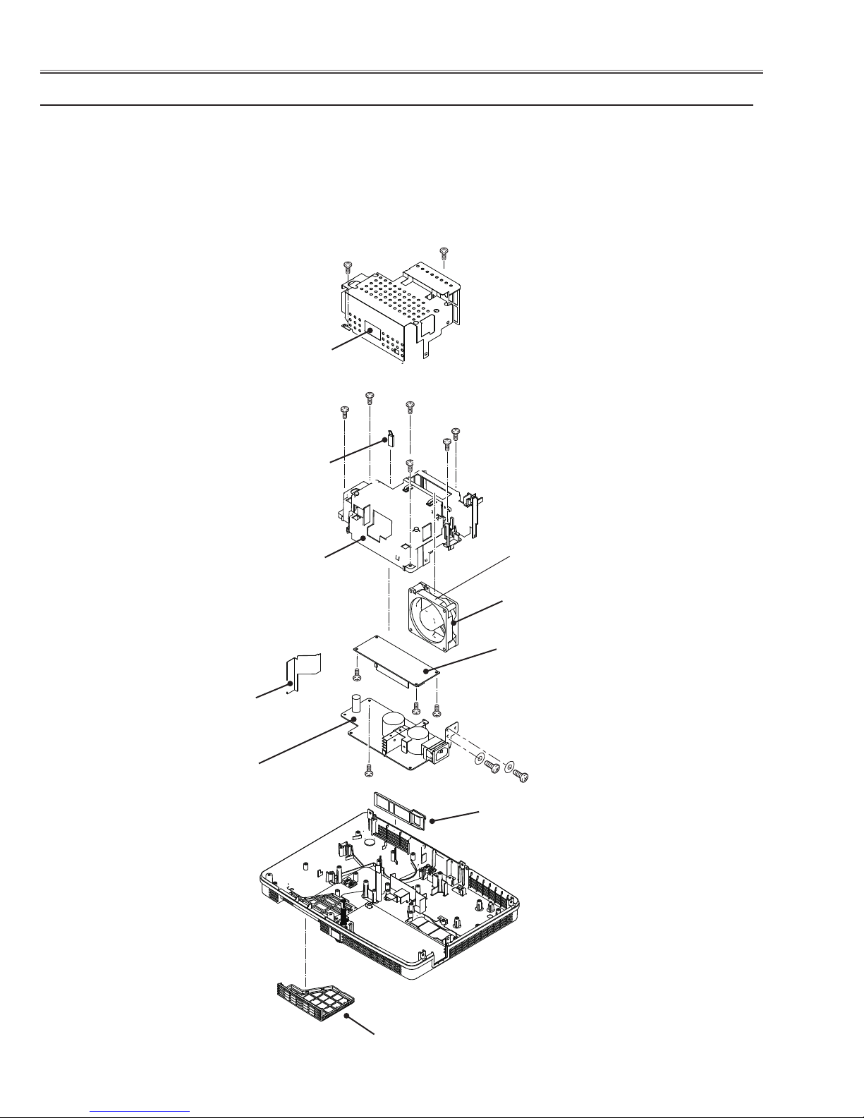
Mechanical Disassembly
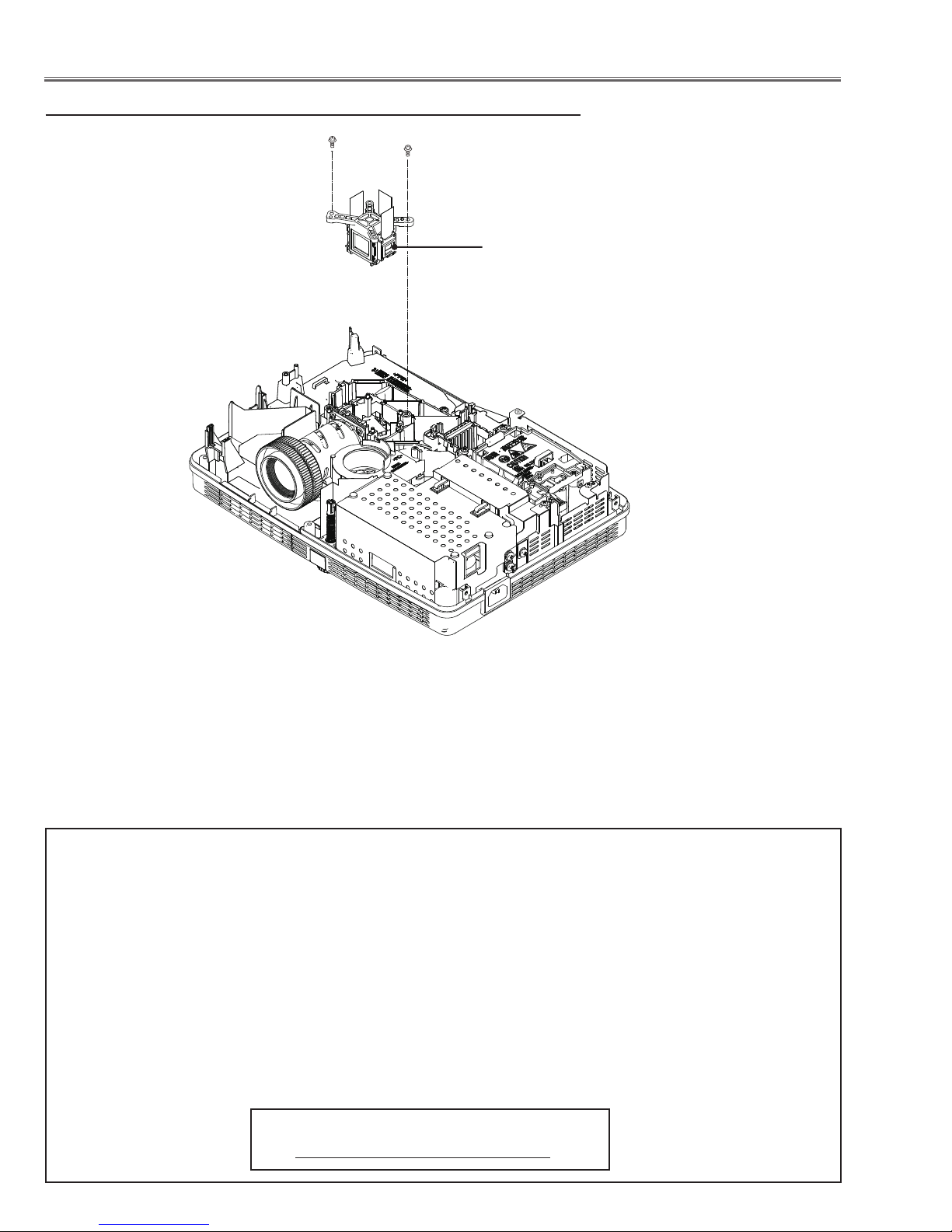
b Power board, Fan(FN002) and Filter removal
1. Remove the Power board spacer sheet.
2. Remove 2 screws A(M3x8) and 2 screws B(M4x6) to remove the Power shield.
3. Remove the thermal switch(SW601). Remove 6 screws C(T3x8) to remove the Power board
holder and the fan(FN002).
4. Remove screw D(T3x8) to remove the Power board.
5. Remove 3 screws E(T3x8) to remove the Lamp Ballast.
6. Remove the Panel net front and Panel net back.
A (M3x8)x2
Power shield
A
Note:
Please pay attention to the install
direction of SW601, the side with
text facing to the projector back.
Power board
spacer sheet
Power board
C(T3x8)x6
SW601
Power board holder
E
D(T3x8)
C
C
C
C
C
The exhaust side facing
to the screening shield.
FN002
Lamp Ballast
E
E(T3x8)x3
B
Panel net back
B (M4x6)x2
Panel net front
Fig.5
-16-
Optical Parts Disassembly
Before taking this procedure, remove Cabinet Top and Main Board following to the “Mechanical Disassembly”.
Disassembly requires a 2.0mm hex wrench and a screwdriver.
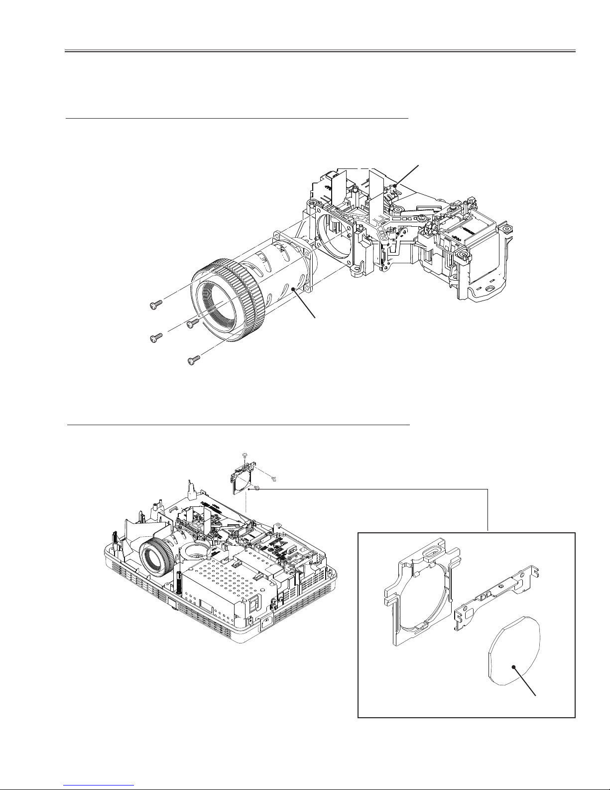
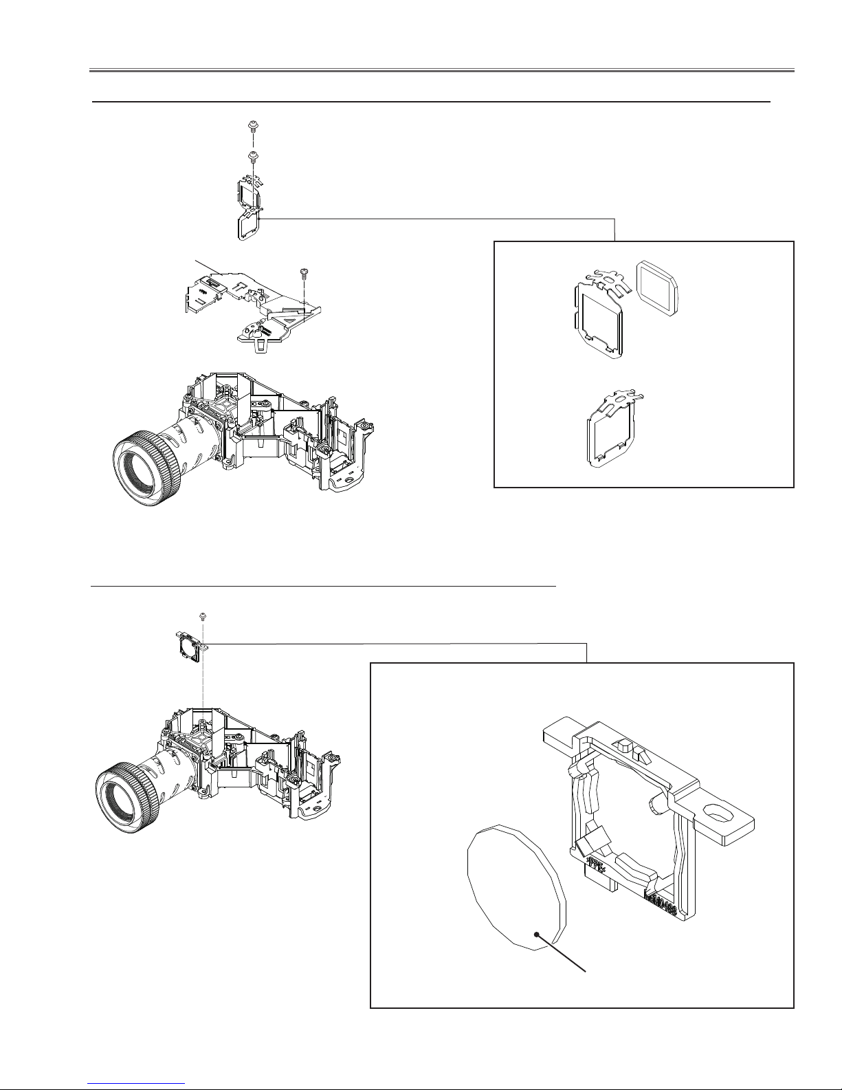
z Projection lens disassembly
Note: The optical unit should be removed from the cabinet bottom before re-
moving the projection lens.
Optical unit
Projection lens
(M2.5x8)x4
x Condenser Out lens disassembly
M(2.5x6)x3
Condenser Out Lens Ass'y
Fig.1
Condenser Out Lens
Fig.2
-17-
Optical Parts Disassembly
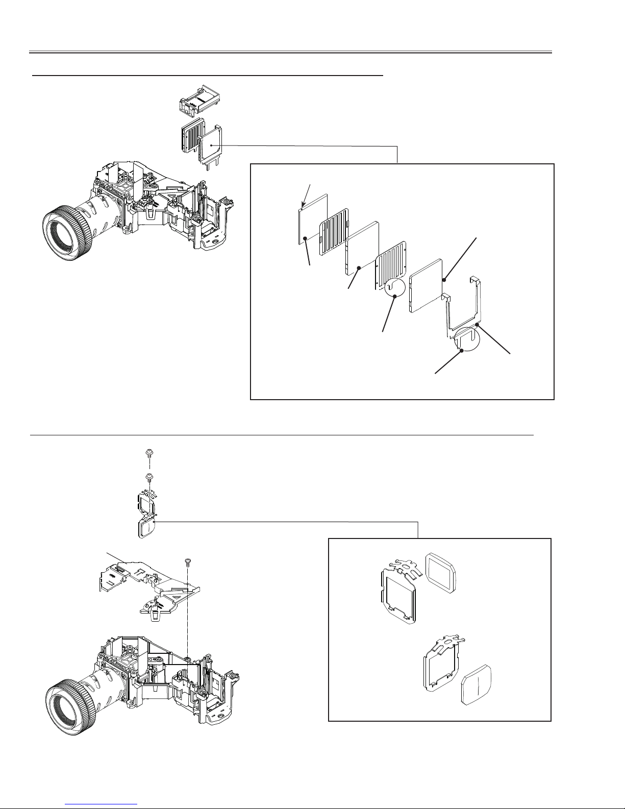
c Integrator lens-in disassembly
Fig.3
Integrator Lens-In Ass'y
PBS marker
Prism Beam Splitter
(PBS)
Integrator lens-out
* Rugged surface
facing to PBS
Release the hook
to remove the lens.
Release the hook
to remove the lens.
* Rugged surface
facing to PBS
Integrator lens-in
Integrator lens-in
Shield
v Condenser Lens Ass'y disassembly (For KR5-XR20100)
(M2.5x6)x2
Condenser Lens Ass'y
Optical unit top
(T3x8)x1
Condenser Lens(G)
Condenser Lens(B)
Fig.4
-18-
Optical Parts Disassembly
v Condenser Lens Ass'y disassembly (For KS5-XR25100)
(M2.5x6)x2
Optical unit top
(T3x8)x1
Condenser Lens (G) Ass'y
Polarized glass (B) Ass'y
*Polarized glass is not re moved from the mounting
base.
Fig.4
b Relay Out lens disassembly
M(2.5x6)
Relay lens Ass'y
Fig.5
Relay Out lens
-19-
Optical Parts Disassembly
n LCD Panel/Prism Ass’y removal
(M3x10)x2
LCD Panel/
Prism Ass’y
Fig.6-1
IMPORTANT NOTICE on LCD Panel/Prism Ass'y Replacement
LCD panels used for this model can not be replaced separately. Do not disassemble the LCD Panel/Prism Ass’y.
These LCD panels are installed with precision at the factory. When replacing the LCD panel, should be replaced
whole of the LCD panels and prism ass’y at once.
After replacing LCD Panel/Prism ass’y, please check the following points.
- Check that there is no color shading at the top, bottom, left or right of the screen. If there is, try to remove the
shading following to the chapter “Optical Adjustment”.
- Check the white balance. If it needs the adjustment, adjust the white balance following to the “White Balance adjustment” , “Gamma adjustment” and “Common Center adjustment” in the chapter “Electrical Adjustment”.
- Check the white uniformity on the screen.
If you find the color shading at the some part of the screen, it needs to take the color shading adjustment. This
adjustment should be performed by a computer and it also requires a special software “Color Shading Correction”.
The software will be supplied separately and can be ordered as follows;
COLOR SHADING CORRECTION Ver. 4.00
Service Parts No. 645 075 9611
-20-
Optical Parts Disassembly
L3P05X-92G00
303kw006B9
-92Gxx
L3P05X-91G00
303kw006B9
-91Gxx
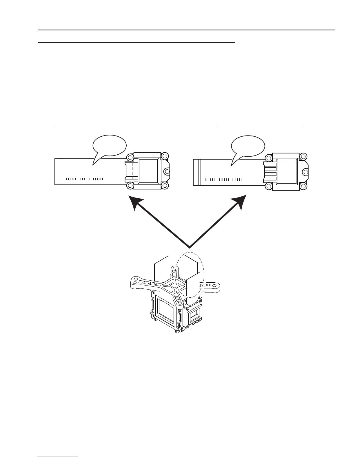
Panel Type Check
There are 2 types of LCD Panel/Prism Ass'y for this model. Either L-Type or R-Type LCD Panel/Prism Ass'y is used
on the projector. Check which type of LCD Panel/Prism Ass'y is used with the figure below.
When replacing the LCD Panel/Prism Ass'y, you need to take "Panel Type Check and Setting" on the Electrical Adjustment for the replaced LCD Panel/Prism Ass'y.
The gamma-characteristics is different between L-Type and R-Type LCD Panel/Prism Ass'y.
How to check the type of LCDPanel/Prism Ass'y
Check the printed number on the flat cable of the G-LCD Panel.
L-Type LCD Panel/Prism Ass'y R-Type LCD Panel/Prism Ass'y
G-LCD PANEL
Fig.6-2
-21-
Optical Parts Disassembly
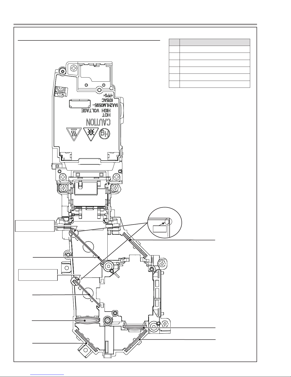
m Locations and Directions(For KR5-XR20100)
When mounting or assembling the optical parts in the optical unit, the parts must be mounted in the specified location and direction as shown in figure below.
No. Parts Name
1 Dichroic mirror (B)
2 Dichroic mirror (G)
3 Relay lens (IN)
4 Mirror (R)
5 Condenser lens (R)
6 Mirror (B)
Marker comes this
side up
1
Marker comes this
side up
2
3
4
Marker
6
5
4
Fig.7
-22-
Optical Parts Disassembly
m Locations and Directions(For KS5-XR25100)
When mounting or assembling the optical parts in the optical unit, the parts must be mounted in the specified location and direction as shown in figure below.
No. Parts Name
1 Dichroic mirror (B)
2 Dichroic mirror (G)
3 Relay lens (IN)
4 Mirror (R)
5 Condenser lens (R)
6 Polarized glass (IN/R)
7 Condenser lens (B)
8 Mirror (B)
Marker comes this
side up
1
Marker comes this
side up
2
3
4
Marker
8
7
6
5
4
Fig.7
-23-
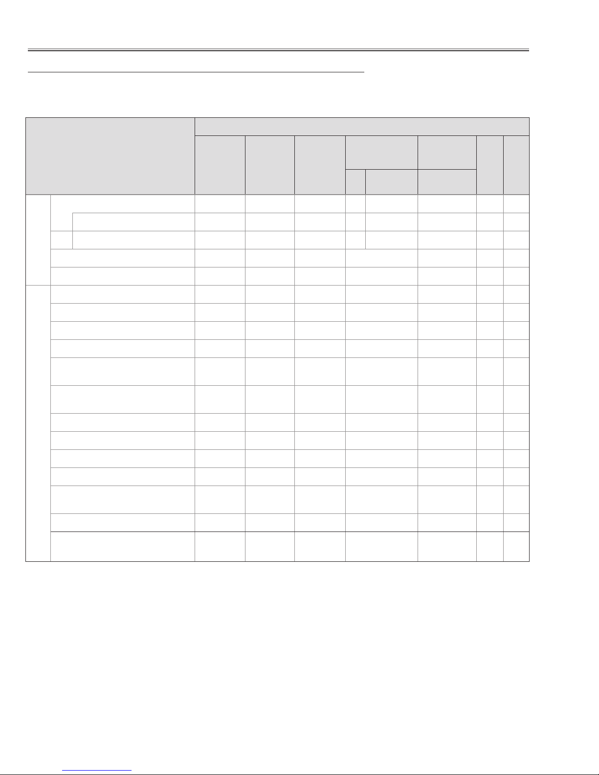
Adjustments
Adjustments after Parts Replacement
LCD/
Prism Ass’y
Contrast Adjustment
Adjustments
Optical
G-Contrast adjustment
❍ ●
● : Adjustment necessary ❍: Check necessary
Disassembly / Replaced Parts
Polarized
Glass
(PLC-XR201)
B
Power
Board
Main
Board
Condenser
Lens (OUT)
Relay
Lens (OUT)
Condensor Glass
G
B
(PLC-XR251)
B-Contrast adjustment
Condenser lens adjustment
Relay lens-out adjustment
Panel type check and setting
Fan control adjustment
Black Level adjustment
Auto calibration adjustment [PC]
Auto c alibrati on ad justment
Electrical Adjustments
[Component]
Auto calibration adjustment
[Video]
Common center adjustment
50% white adjustment [PC]
White balance adjustment [PC]
50% white adjustment [Video]
Whi t e bala nce adj ustmen t
[Video]
Keystone offset adjustment
❍ ● ●
❍ ●
❍ ●
● ●
● ●
●
●
●
●
● ●
● ●
❍ ❍
● ●
❍ ❍
●
Color shading correction adjustment
❍ ❍
Caution:
Don't unplug the AC Cord without pressing the power button in the serving.
-24-
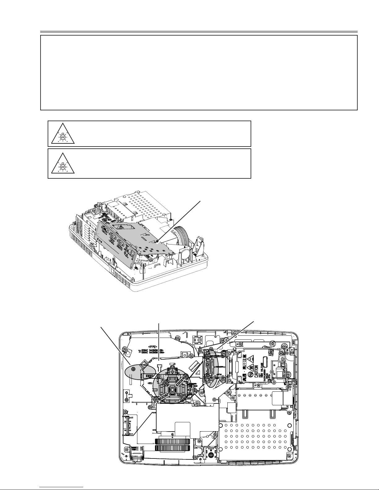
Optical Adjustments
Before taking optical adjustments below, remove the Cabinet Top following to the “Mechanical Disassembly”.
Remove the Main board and remove the AV panel. (Refer to Fig. 1)
Adjustments require a 2.0mm hex wrench and a slot screwdriver. When you adjust condenser lens (OUT) or Relay
lens (OUT) adjustment, you need to disconnect FPC cables of LCD panels on the main board.
Optical adjustment requires a 2.0mm hex wrench and a slot screwdriver.
Note: Do not disconnect connectors on the main board, because the projector cannot turn on due to operate the
power failure protection.
WARNING : USE UV RADIATION EYE AND SKIN PRO-
TECTION DURING SERVICING
CAUTION: To prevent suffer of UV radiation, those adjust-
ment must be completed within 25 minutes.
DURING SERVICING
Main board
Fig. 1
Relay Lens (OUT)
Adjustment
Contrast Adjustment
The AV panel is removed, and the
MAIN board is lifted.
Condenser Lens (OUT) Adjustment
-25-
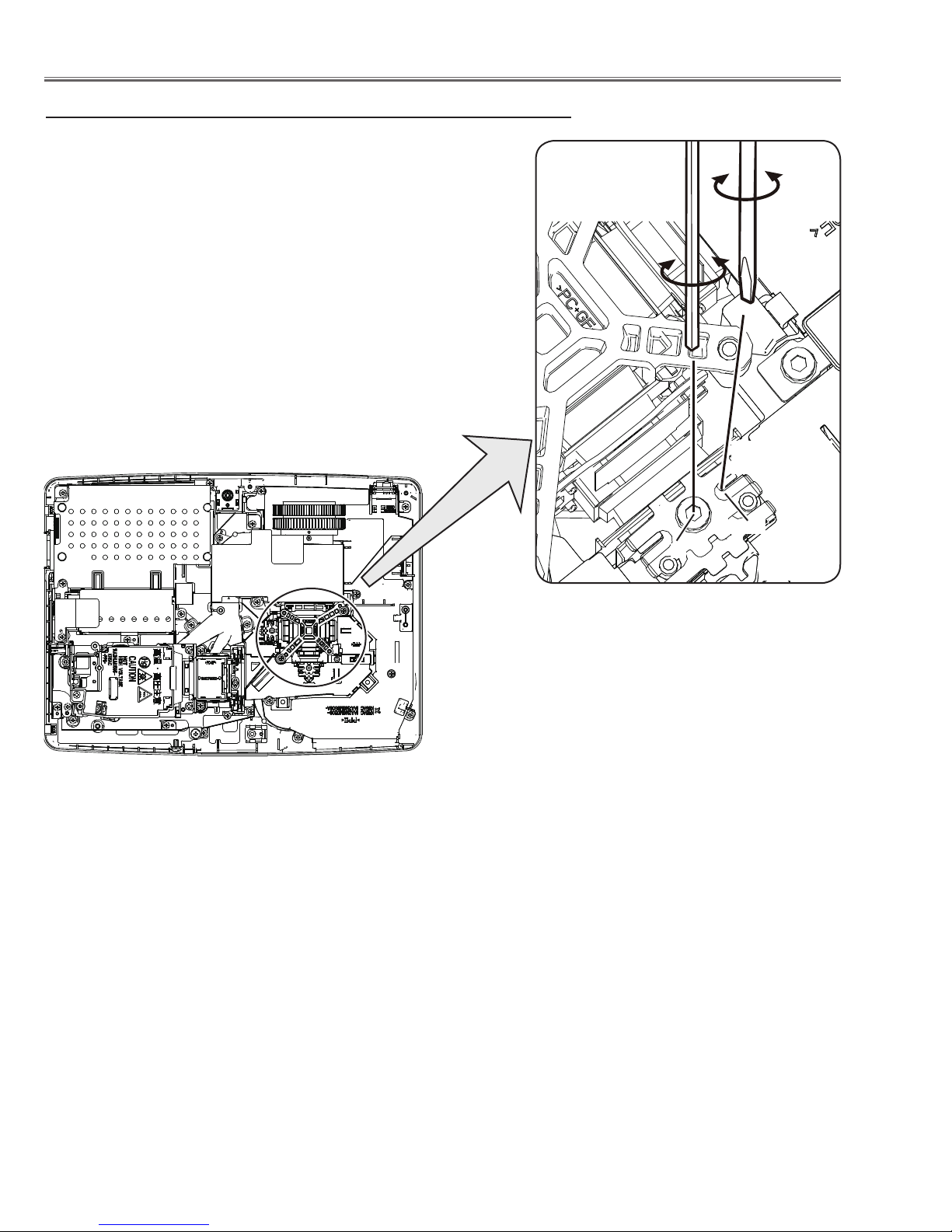
Optical Adjustments
Contrast adjustment
[Before Adjustment]
- Input a 100% of black raster signal.
1 Loosen a screw A (Fig.2) on the polarized glass mounting base
which you intend to adjust.
2 Adjust the slot B to obtain the darkest brightness on the screen by
using a slot screwdriver.
3 Tighten the screw A to fix the polarized glass mounting base.
Repeat steps 1 to 3 for remaining polarized glasses.
Polarized glass
mounting base
Slot B
A
Fig.2
-26-
Optical Adjustments
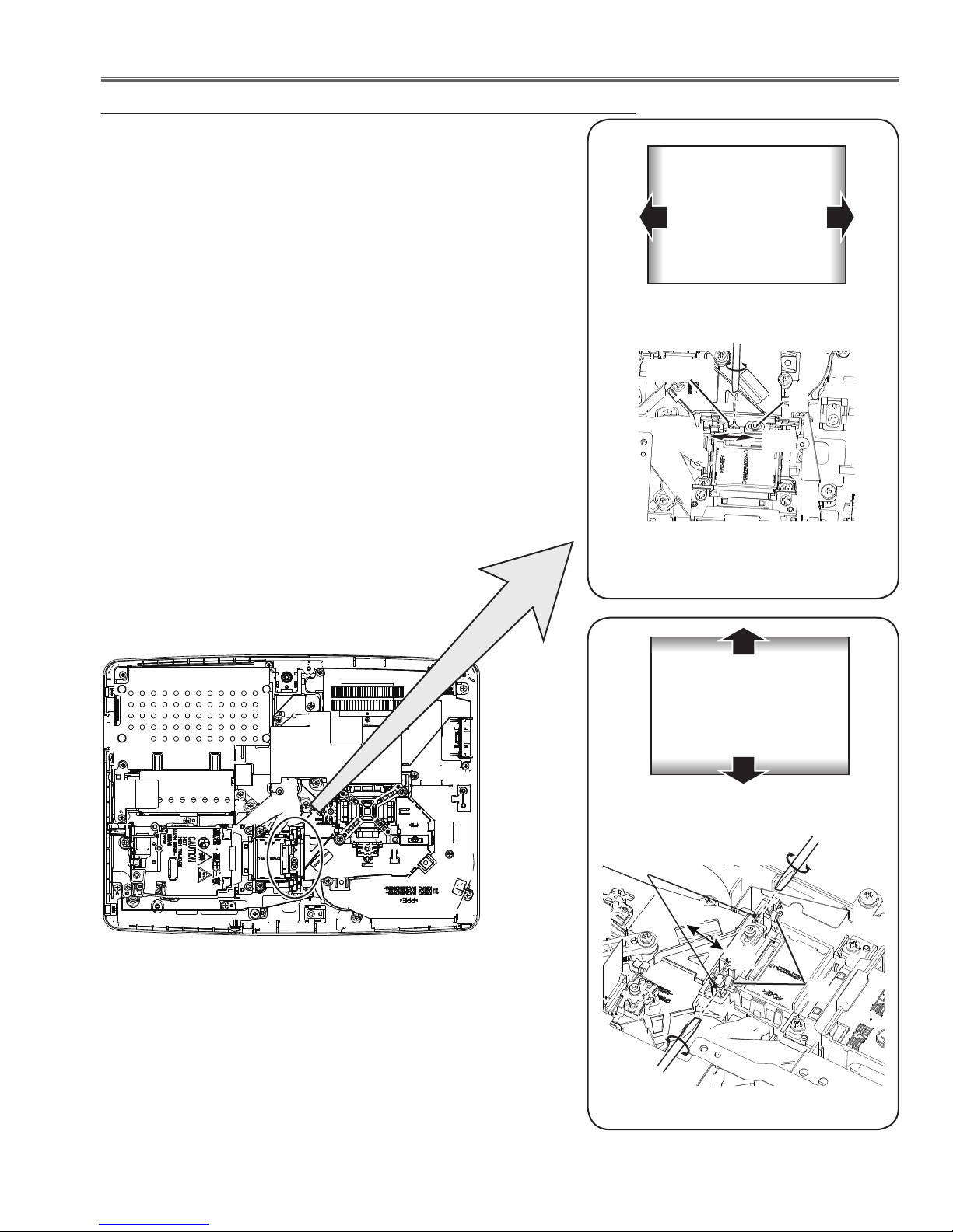
Condenser Out lens adjustment
1 Turn the projector on by a state of without FPC cables.
2 Project all of lights on the screen.
3 Adjust the adjustment base of condenser out lens assy to make
color uniformity in white.
1) If the shading appears on the left or right of the screen as shown
in Fig.3-1, loosen 1 screw A , and adjust the slot B to make
color uniformity in white by using a slot screwdriver.
2) If the shading appears on the top or bottom of the screen as
shown in Fig.3-2, loosen 2 screws C, and adjust the slots D to
make color uniformity in white by using a slot screwdriver
4 Tighten screws A and C to fix the condenser out lens unit.
a
White
b
Note:
The relay lens adjustment must be carried out after completing this
adjustment.
Slot B
a
Fig.3-1
Moving of slot B
A
b
x
White
y
Slot D
x
y
C
Fig.3-2
Moving of Slot D
-27-
Optical Adjustments
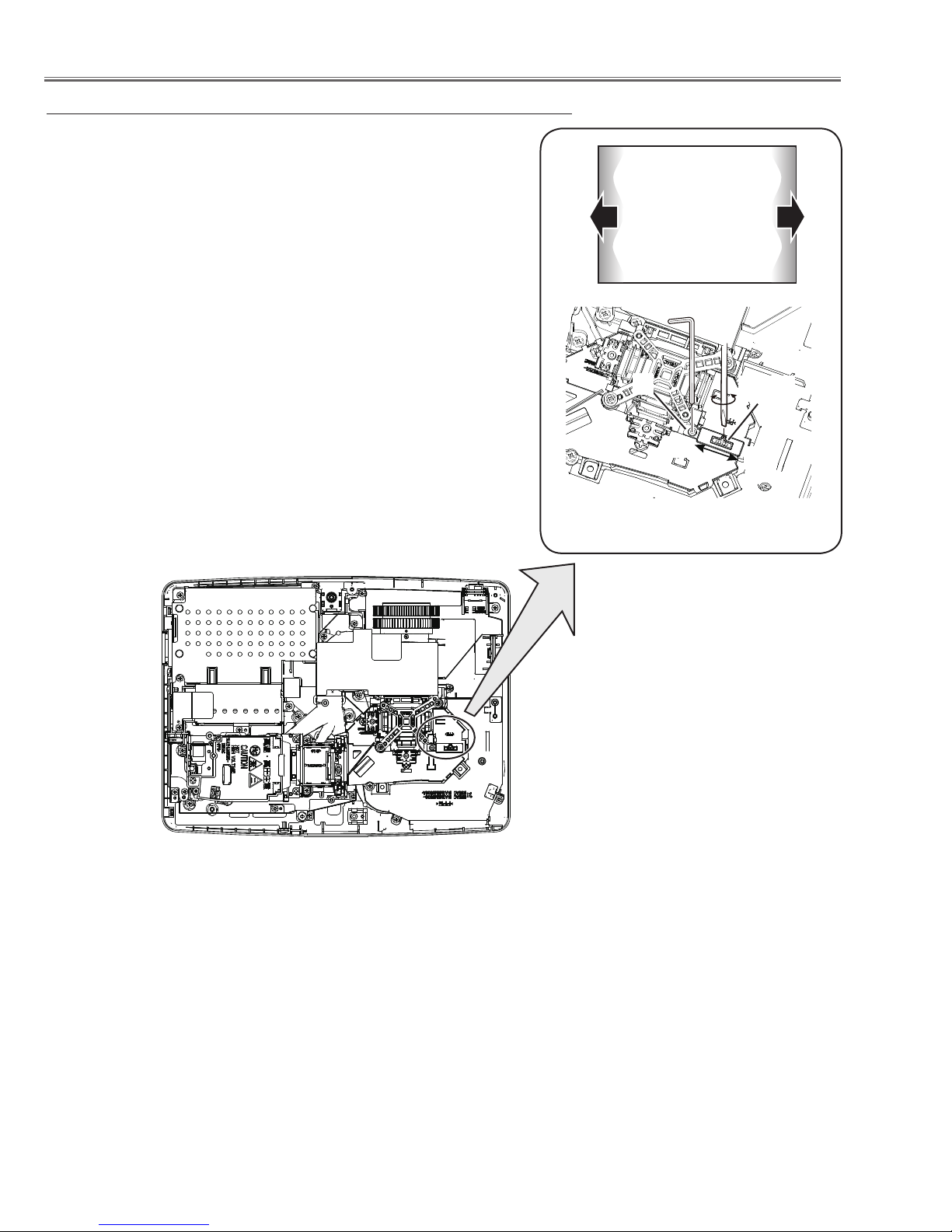
Relay lens-Out adjustment
1 Turn the projector on by a state of without FPC cables.
2 Project all of lights on the screen.
3 Adjust the adjustment base of relay lens assy to make color unifor-
mity in white.
If the shading appears on the left or right of the screen as shown in
Fig.3, loosen 1 screw A by using a hex screwdriver, and adjust the
slot B to make color uniformity in white by using a slot screwdriver.
4 Tighten the screw A to fix the relay lens unit.
b
White
a
A
Fig.3
Moving of slot B
Slot B
a
b
-28-
Service Mode
Input Computer 1
Group No. Data
0
0 +179
Ver. R 0.00 KR5AC
Electrical Adjustments
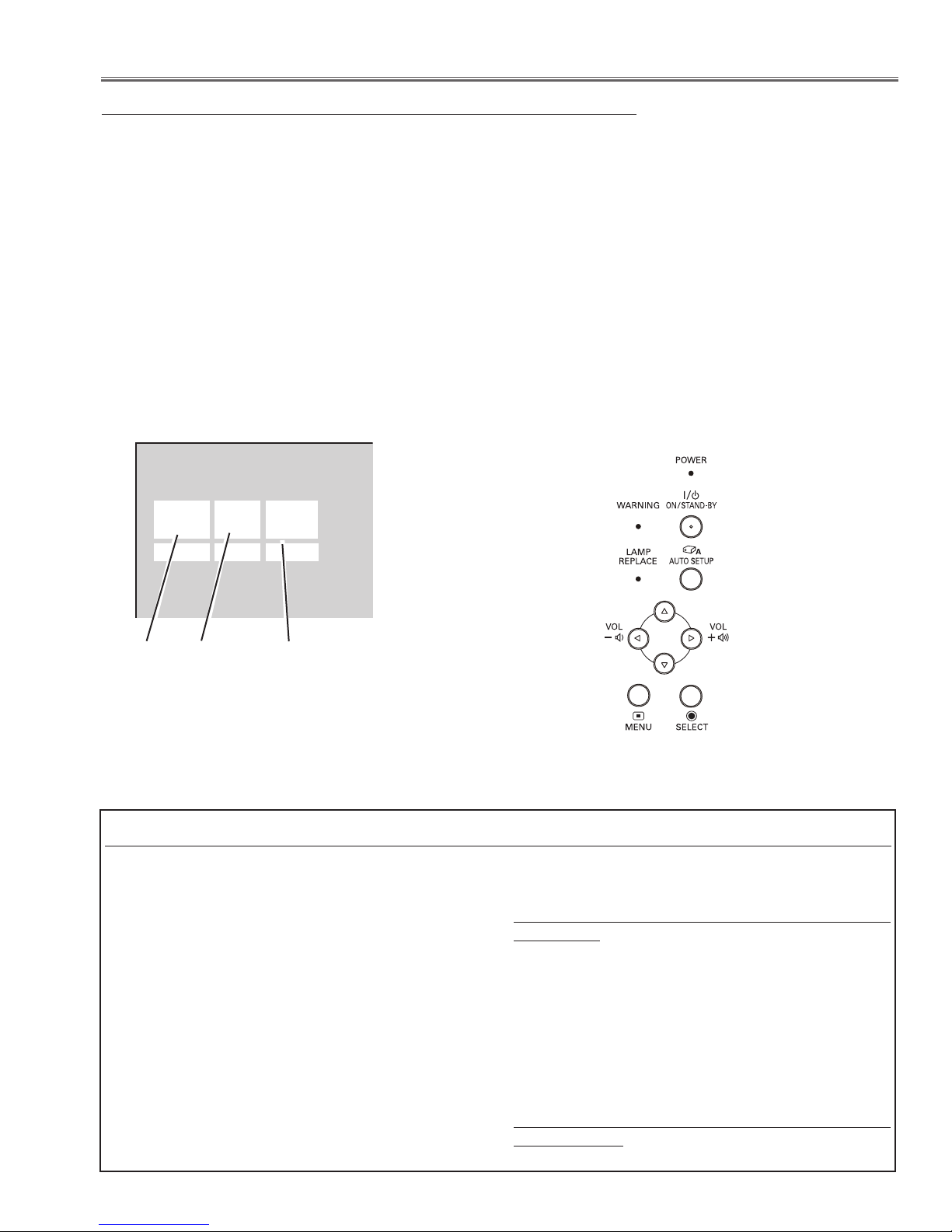
Service Adjustment Menu Operation
To enter the service mode
To enter the “Service Mode”, press and hold the MENU and SELECT button for more than 3 seconds. The service
menu appears on the screen as follows.
To adjust service data
Select the adjustment group no. by pressing the MENU button (increase) or SELECT button (decrease), and
select the adjustment item no. by pressing the pointer e or d button, and change the data value by pressing the 7
or 8 button. Refer to the “Service Adjustment Data Table” for further description of adjustment group no., item no.
and data value.
To exit the service mode
To exit the service mode, press the ON/STAND-BY button.
Group No.
Item No.
Data value
Memory IC (IC1371) Replacement
Memory IC on the main board stores the data for
the service adjustments, and should not be replaced
except for the case of defective device.
If replaced, the re-adjustments are required following
to the “Electrical Adjustments”.
The data of lamp replacement counter is stored in the
Memory IC.
Please note that the lamp replace counter will be
reset when the memory IC is replaced.
(Lamp replace counter cannot be set to the previous
value.)
● Caution to memory IC replacement
When memory IC is replaced with new one, the CPU
writes down the default data of the service adjustments to the replaced IC as the mentioned on the
service adjustment table. As these data are not the
same data as factory shipped data, it should be
required to perform the re-adjustments following to the
“Electrical Adjustments”.
Please note that in this case the lamp replace counter
will be reset.
● Caution of Main Board replacement (in the case
memory IC is not defective)
When the main board is replaced, memory IC should
be replaced with the one on previous main board.
After replacement, it should be required to perform the re-adjustments following to the “Electrical
Adjustments”.
In this case, the lamp replace counter can be kept the
value as before.
-29-
Electrical Adjustments
White 100%
Black 100%
W
Y C
G
M
R
B
BLK
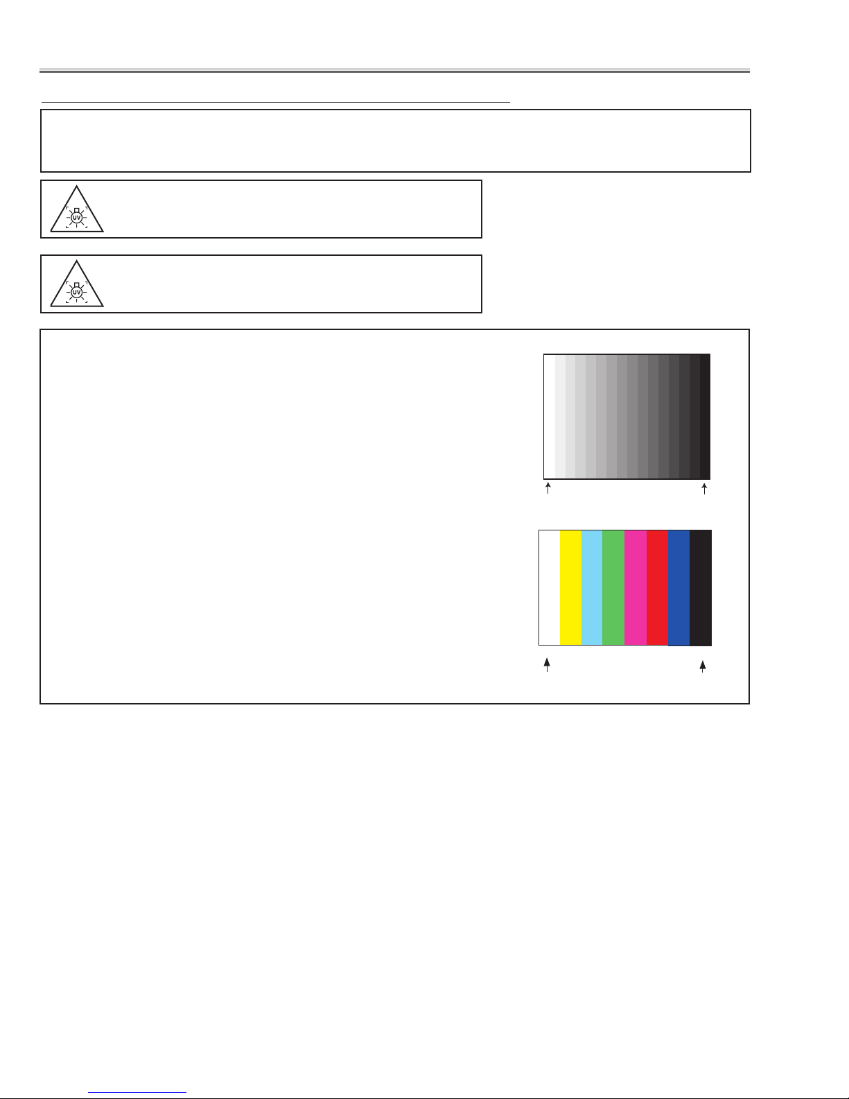
Circuit Adjustments
CAUTION: The each circuit has been made by the fine adjustment at factory. Do not attempt to adjust the following
adjustments except requiring the readjustments in servicing otherwise it may cause loss of performance
and product safety. Before adjustment, please turn on the projector more than ten minutes.
WARNING : USE UV RADIATION EYE AND SKIN
PROTECTION DURING SERVICING.
CAUTION:
To prevent suffer of UV radiation, those adjustments
must be completed within 25 minutes.
[Adjustment Condition]
● Input signal
Video signal .......................
1.0Vp-p/75W terminated, 16 steps gray scale
(Composite video signal)
Component Video signal ...... 1.0Vp-p/75W terminated, 8 color 100% color
bar or 16 step gray scale (Component video
signal)
Computer signal ................... 0.7Vp-p/75W terminated, 16 steps gray scale
pattern
● Image control mode ......... “STANDARD” mode unless otherwise noted.
Note:
* Please refer to “Service Adjustment Menu Operation” for entering the
service mode and adjusting the service data.
16 steps gray scale pattern
8 color 100% color bar
White 100%
Black 100%
-30-
 Loading...