

Sanyo PLC-XP50,PLC-XP50L Service Manual
Multimedia Projector
SERVICE MANUAL
(SUPPLEMENT)
PRODUCT CODE
1 122 187 00
(MS3AA)
1 122 187 20 (MS3AM)
1 122 188 00 (PS3AA)
1 122 188 20 (PS3AM)
1 122 188 02 (PS3CA)
1 122 188 22 (PS3CM)
Original Version
REFERENCE NO. SS5110575
FILE NO.
Model No. PLC-XP50
PLC-XP50L
U.S.A., Canada,
Europe, Asia, Africa
PLC-XP50
Chassis No. MS3-XP5000
MS3-XP50L00
NOTE: Match the Chassis No. on the unit’s
back cover with the Chassis No. in the
Service Manual.
If the Original Version Service
Manual Chassis No. does not match
the unit’s, additional Service
Literature is required.You must refer to
“Notices” to the Original Service
Manual prior to servicing the unit.
Note:
Model PLC-XP50L does not provide projection lens.
FILE WITH ORIGINAL SERVICE MANUAL (SM5110500)
- NOTE -
Any information not contained in this manual will be found in the original model's service manual
SM5110500-00 for models PLC-XP55 and PLC-XP55L.

2
■ Contents
■ Specifications __________________________________________________ 3
■ Optical parts disassemblies ________________________________________ 4
■ Optical adjustments ______________________________________________ 5
● Contrast adjustment ________________________________________ 5
■ Adjustments after parts replacement ________________________________ 6
■ Electric adjustments____________________________________________ 7-24
● Circuit adjustments ______________________________________ 7-11
● Service adjustment data table ______________________________ 12-23
● Test points and locations ____________________________________ 24
■ Chassis block diagrams________________________________________ 25-28
■ Power supply lines ______________________________________________ 29
■ Troubleshooting ________________________________________________ 27
● No picture ________________________________________________ 27
■ Control port functions ____________________________________________ 30
■ Waveforms ____________________________________________________ 31
■ IC block diagrams ______________________________________________ 32
■ Service parts lists ____________________________________________ 33-71
● Electrical parts list ______________________________________ 33-65
● Mechanical parts list ____________________________________ 66-67
● Optical parts list ________________________________________ 68-71
Drawings & Diagrams ______________________________________ A1-A17
■ Parts description and reading in schematic diagram____________________ A2
■ Schematic diagrams ________________________________________ A3-A10
■ Printed wiring board diagrams ________________________________ A11-A16
■ Pins description of ICs, transistors, diodes __________________________ A17
- NOTE -
Any information not contained in this manual will be found in the original model's service manual
SM5110500-00 for models PLC-XP55 and PLC-XP55L.
MAJOR CHANGES as below:
- LCD Panels and LCD driving circuit
- Projection Lens
- Optical parts
-3-
■ Specifications
● The specifications are subject to change without notice.
This symbol on the nameplate means the product is Listed by Underwriters
Laboratories Inc. It is designed and manufactured to meet rigid U.L. safety standards against risk of fire, casualty and electrical hazards.
Projector Type Multi-media Projector
Dimensions (W x H x D) 12.6” x 6.6” x 16.8” (319mm x 168mm x 429.5mm)
Net Weight 19.2 lbs (8.7 kg) (PLC-XP50),
16.3 lbs (7.4 kg) (PLC-XP50L)
LCD Panel System 1.3” TFT Active Matrix type, 3 panels
Panel Resolution 1024 x 768 dots
Number of Pixels 2,359,296 (1024 x 768 x 3 panels)
Color System PAL, SECAM, NTSC, NTSC4.43, PAL-M and PAL-N
High Definition TV SIgnals 480i, 480p, 575i, 575p, 720p, 1035i and 1080i
Scanning Frequency H-sync. 15 ~ 100kHz, V-sync. 50 ~ 100Hz
Projection Lens F 1.8 ~2.1 lens with f=48.4mm ~ 62.8mm motor zoom and focus (PLC-XP50)
Throw Distance 4.6’ ~ 47.3’ (1.4m ~ 14.4m) (PLC-XP50)
Motorized Lens Shift Up and Down
Projection Image Size (Diagonal) Adjustable from 31” to 400”
Horizontal Resolution 800 TV lines (HDTV)
Projection Lamp 300 watt type
Input 1/Monitor Output Jacks DVI Terminal (Digital) HDCP Compatible, HDB 15-pin Terminal (Analog)
and Stereo Mini Type Jack (Audio)
Input 2 Jacks BNC Type x 5 (G or VIDEO/Y, B or Cb/Pb, R or Cr/Pr, H and V),
Stereo Mini Type Jack (Audio)
Input 3 Jacks RCA Type x 3 (VIDEO/Y, Cb/Pb, Cr/Pr), RCA Type x 2 (Audio R and L)
and DIN 4-pin (S-Video)
Other Jacks DIN 8-pin (Control port), USB port (Series B receptacle),
Wired Remote Jack and PJ-Net Organizer Connector
Built-in Speakers INT. SP. Stereo (R and L), 2 watts RMS (T.H.D. 10%)
Feet Adjustment 0˚ to 10.5˚
Voltage and AC 100 ~ 120V (5.0A Max. Ampere), 50/60Hz (The U.S.A and Canada)
Power Consumption AC 200 ~ 240V (2.5A Max. Ampere), 50/60Hz (Continental Europe and The U.K.)
Operating Temperature 41 ˚F ~ 95 ˚F (5˚C ~ 35˚C)
Storage Temperature 14 ˚F ~ 140 ˚F (-10˚C ~ 60˚C)
Remote Control Transmitters Wireless/Wired Remote Control, batteries AA, UM3 or R06 Type x 2
The CE Mark is a Directive conformity mark of the European Community (EC).
-4-
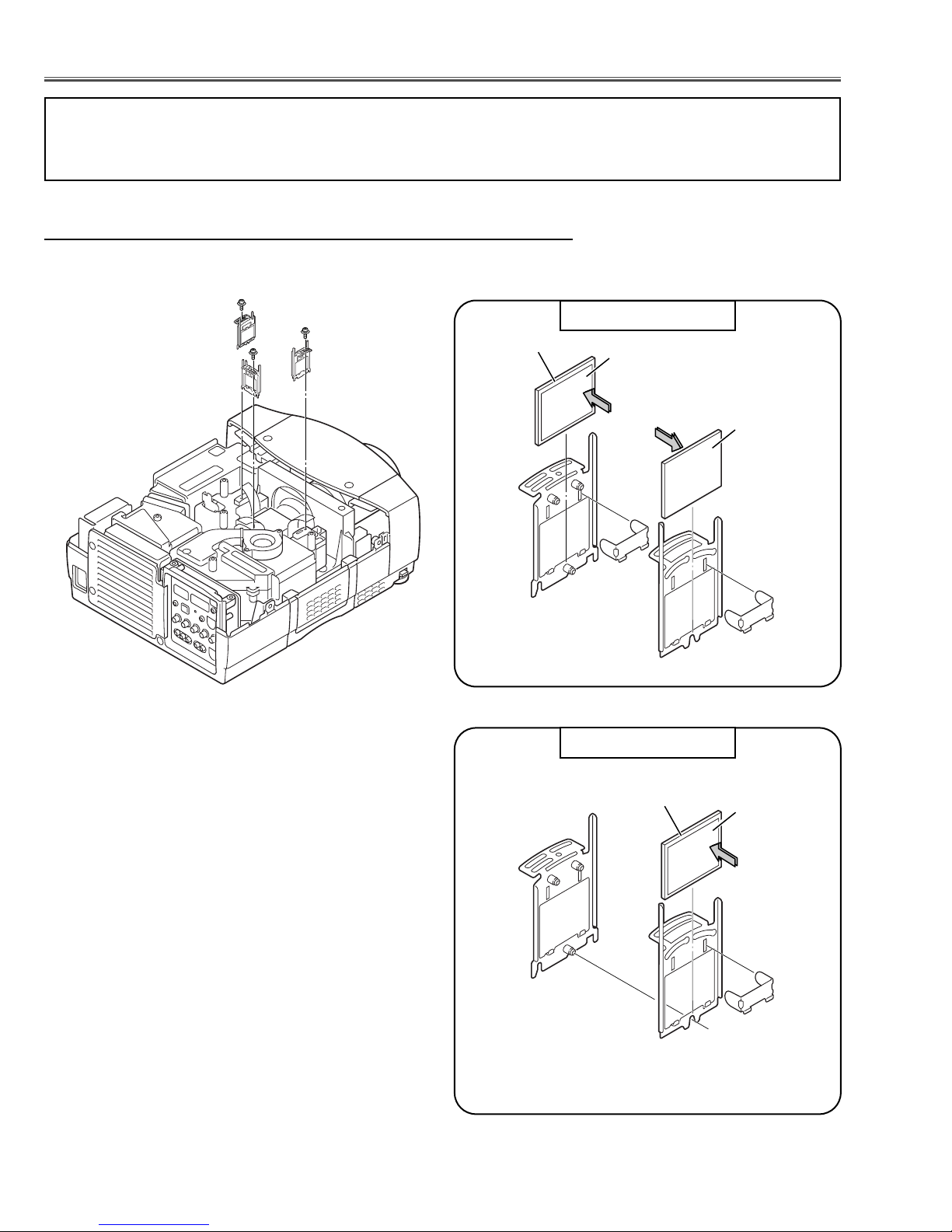
■ Optical Parts Disassemblies
1 Remove each hex screw and pull the Polarized Glass-In ass’y upward.
2 Remove a stopper and take the glass off upward.
Optical Filter
Polarized Grass
1AV4Z15***
Par t No.
Film side
Polarized Glass-In and Optical Filter-In(WV) removal
Fig.1-
1
Fig.1-2
* Following assemblies differ from previous assemblies for chassis No. MR3-XP5500 others are the same;
- The optical filters has been added.
Polarized Grass
1AV4Z15***
Par t No.
Film side
Fig.1-3
RED & GREEN
BLUE
BLUE
RED
GREEN
-5-
Fig.1-1
Polarized glass
mounting base
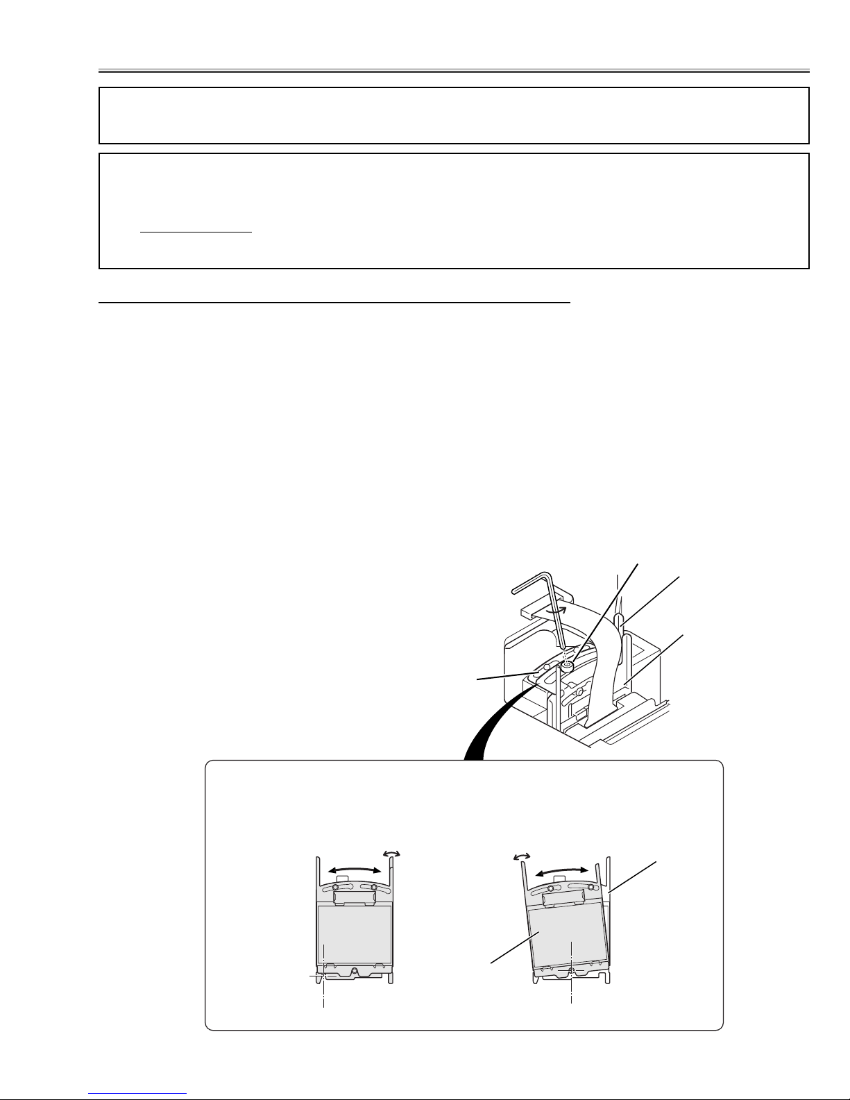
■ Optical Adjustments
A
Before taking optical adjustments below, remove the Cabinet Top and Main Board following to the “Mechanical
Disassemblies”
Adjustments require a 2.0mm hex wrench and a slot screwdriver.
Note: Do not disconnect
connectors K8L, K8X, K8D, K8G and K8E on the main board, because the projector can
not turn on due to operate the power failure protection.
Fig.1-
2
B
Fig.1-3
C
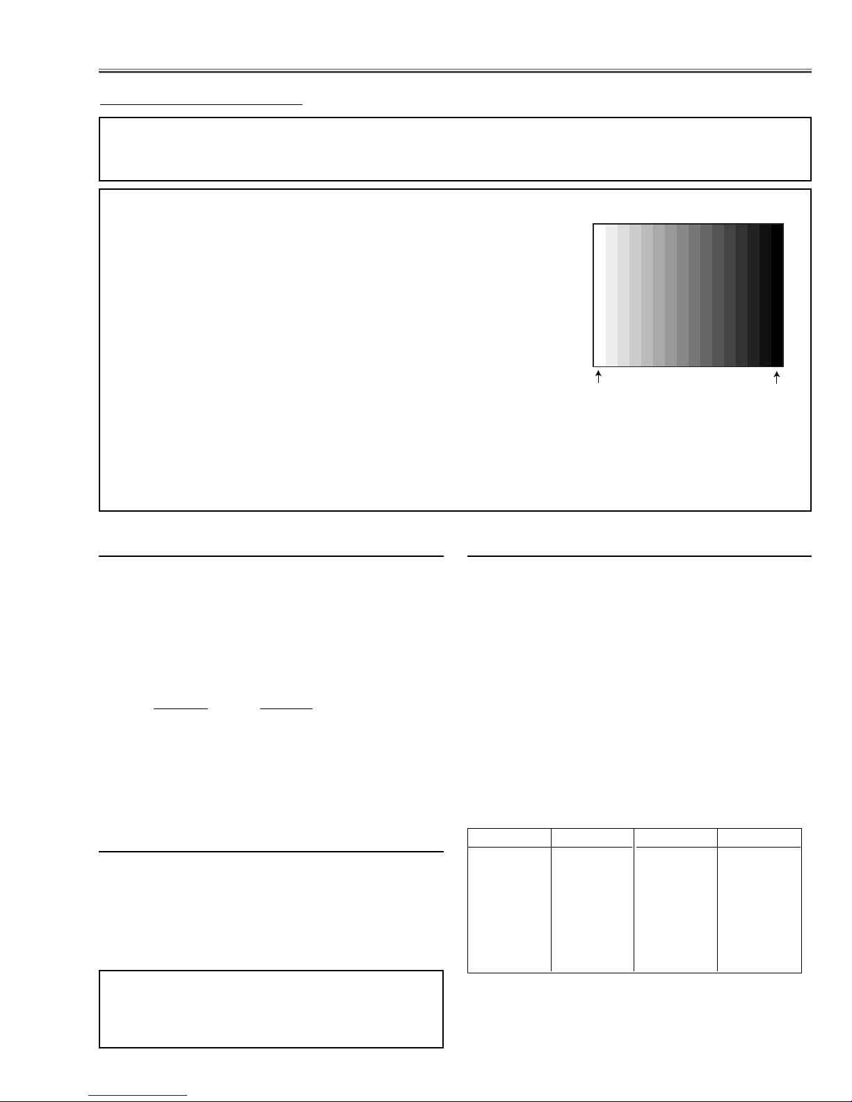
[Before Adjustment]
- Input a 100% of black raster signal.
[R/G/B-CONTRAST ADJUSTMENT]
1 Loosen a screw A (Fig.1-1) on the polarized glass mounting base which
you intend to adjust.
2 Turn the polarized glass mounting base with knob B as shown in Fig.1-2
to obtain the darkest brightness on the screen. (The polarized glass and
optical filter move together.)
3 Tu rn the optical filter mounting base with knob C as shown in Fig.1-3 to
obtain the black color uniformity on the screen.(Move only the optical filter.)
4 Tighten the screw A to fix the polarized glass mounting base.
Repeat steps 1 to 4 for remaining R, G or B contrast adjustment.
Note : Blue contrast adjustment
The 3rd step may be ignored because of no optical filter(WV).
Contrast adjustment
* Following adjustment differs from previous adjustment for chassis No. MR3-XP5500 others are the same;
- Contrast adjustment
Polarized Glass
Optical Filter(WV)
Polarized Glass
Optical Filter(WV)
-6-
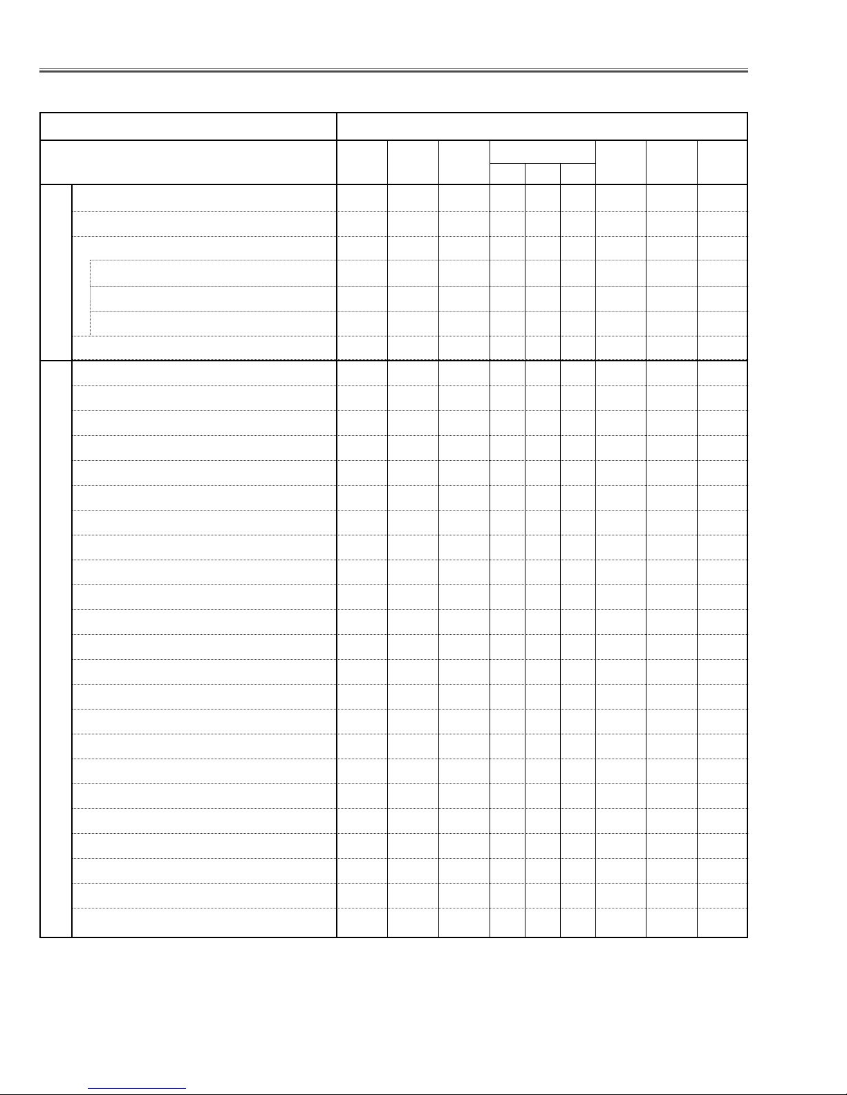
● : Adjustment necessary ❍ : Check necessary
■ Adjustments after Parts Replacement
Condenser lens adjustment ❍●
Relay lens adjustment ❍●
Contrast Adjustment
R-Contrast adjustment ●
G-Contrast adjustment ●
B-Contrast adjustment ●
Output voltage adjustment ❍
+16 V adjustment ❍
Fan output voltage adjustment ●●
NRS adjustment ●
Video center adjustment ●
PC black level adjustment ●
PC pedestal adjustment ●
PC gain adjustment ●
PC signal offset adjustment ●
Video A/D reference voltage top & bottom adj. ●
Video pedestal adjustment ●
Video gain adjustment ●
Video signal offset adjustment ●
Component pedestal adjustment ●
Component A/D reference voltage top adjustment ●
Component gain adjustment ●
RGB pedestal adjustment ●
RGB A/D reference voltage top adjustment ●
RGB gain adjustment ●
Common center adjustment ●●
PC white balance adjustment ❍❍
Video white balance adjustment ❍❍
Disassembly / Replaced Parts
LCD/
Prism
Ass’y
Condenser
Lens
Polarized glass
RGB
Optical Adjustments
Electrical Adjustments
Sub
Powe r
Board
Main
Board
Relay
Lens
Powe r
Board
-7-
● Circuit Adjustments
CAUTION: The each circuit has been made by the fine adjustment at factory. Do not attempt to adjust the follow-
ing adjustments except requiring the readjustments in servicing otherwise it may cause loss of performance and product safety.
■ Electrical Adjustments
[Adjustment Condition]
● Input signal
Video signal .......................... 1.0Vp-p/75Ω terminated, 16 steps gray
scale, white 100% and black 0% pattern (Composite video signal)
Computer signal .................... 0.7Vp-p/75Ω terminated, 16 steps gray
scale pattern (XGA)
Component Video signal ........ 0.7Vp-p/75Ω terminated, 16 steps gray
scale, white 100% and black 0% pattern (480i format)
RGB Video signal .................. 0.7Vp-p/75Ω terminated, 16 steps gray
scale, white 100% and black 0% pattern (480p format)
● Picture control mode ................ “STANDARD” mode unless otherwise noted.
Note:
* Please refer to “Service Adjustment Menu Operation” in the original model's service manual for entering to the
service mode and adjusting the service data.
After replacing the Power Board readjust the Output
voltage adjustment as follows.
1. Connect a digital voltmeter to pin 1 (+) of K6A and
chassis ground (-).
2. Adjust the voltage by using VR601 on the power
board as following.
AC Input Reading
230V 370 ±2Vdc
or 120V 356 ±2Vdc
Caution:
Be sure to connect the lamp when taking this adjustment.
z Output voltage adjustment
1. Receive the 16-step gray scale video signal with
Input 3 [VIDEO] mode.
2. Connect a digital voltmeter to pin 3 (+) of CN6A and
chassis ground (-).
3. Adjust the voltage to be 16.0 ±0.1Vdc by using
VR681 on the power board.
x +16V adjustment
16 steps gray scale pattern
1. Enter the service mode.
2. Connect a digital multimeter to test point “TPFN❊”(+)
and chassis ground (-). (as shown below)
3. Select group no. “11”, item no. “24” and change data
value of the fan number. (as shown below)
4. Select item no.“41” and change data value to adjust
the fan max. output voltage to be 14.0 ±0.1V.
5. Select item no.“42” and change data value to adjust
the fan min. output voltage to be 6.5 ±0.1V.
6. Each fan should be adjusted refer to item 2 - 5.
Note:
The location of each fan is refer to the parts list.
c Fan voltage adjustment
FAN No. Group/Item
FN901 11 / 24
FN902 11 / 24
FN903 11 / 24
FN904 11 / 24
FN905 11 / 24
FN906 11 / 24
FN907 11 / 24
Data Test point
0 TPFN1
0 TPFN1
2 TPFN3
5 TPFN4
1 TPFN5
4 TPFN6
3 TPFN7
Note:
The Power Board for replacing is already adjusted in
the factory, so it is not required to perform readjustment of item1 and 2.
White 100%
Black 100%
-8-
1. Receive the 16-step gray scale computer signal with
Input 1 [RGB(Analog)] mode.
2. Enter the service mode.
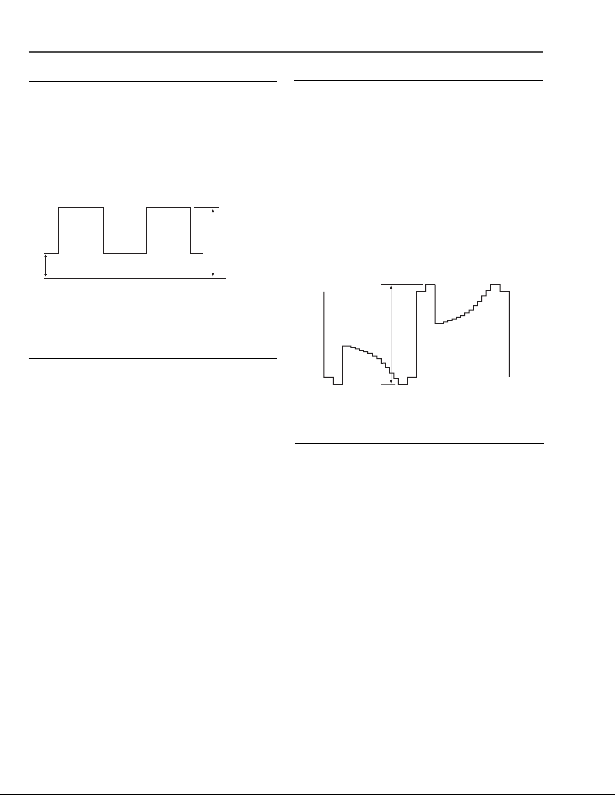
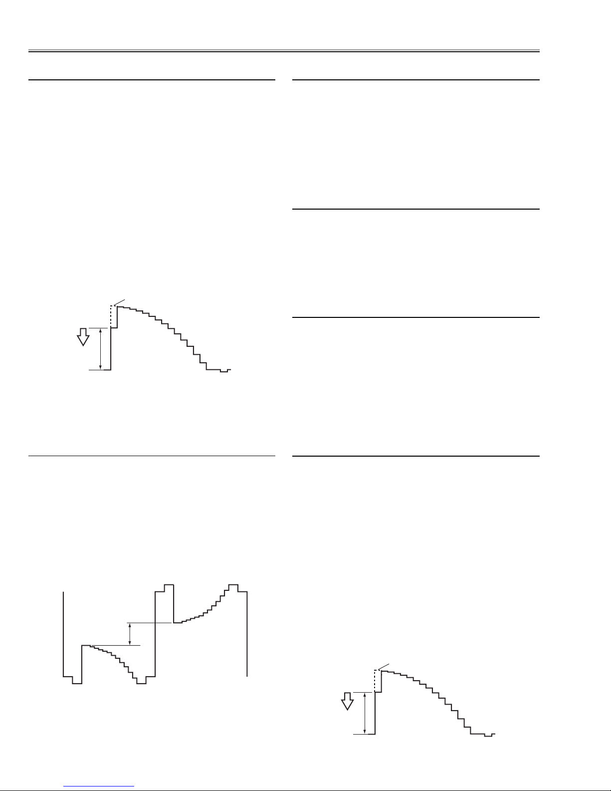
3. Connect an oscilloscope to test point “TPNRS”(+)
and chassis ground (-).
4. Select group no. “5”, item no. “4” and change data
value to adjust amplitude “a” to be 2.0 ±0.1V.
5. Select item no. “3” and change data value to adjust
amplitude “b” to be 7.0 ±0.1V.
v NRS adjustment
1. Receive the 16-step gray scale computer signal with
Input 1 [RGB(Analog)] mode.
2. Enter the service mode.
3. Connect a digital voltmeter to test point “TPV1G”(+)
and chassis ground (-).
4. Select group no. “5”, item no. “5” and change data
value to adjust the voltage to be 6.50 ±0.1Vdc.
5. Connect a digital voltmeter to test point “TPV1B”(+)
and chassis ground (-).
6. Select item no. “6” and change data value to adjust
the voltage to be 6.50 ±0.1Vdc.
7. Connect a digital voltmeter to test point “TPV1R”(+)
and chassis ground (-).
8. Select item no. “7” and change data value to adjust
the voltage to be 6.50 ±0.1Vdc.
9. Connect a digital voltmeter to test point “TPV2G”(+)
and chassis ground (-).
10. Select group no. “5”, item no. “8” and change data
value to adjust the voltage to be 7.50 ±0.1Vdc.
11. Connect a digital voltmeter to test point “TPV2B”(+)
and chassis ground (-).
12. Select item no. “9” and change data value to adjust
the voltage to be 7.50 ±0.1Vdc.
13. Connect a digital voltmeter to test point “TPV2R”(+)
and chassis ground (-).
14. Select item no. “10” and change data value to adjust
the voltage to be 7.50 ±0.1Vdc.
b Video center adjustment
1. Receive the 16-step gray scale computer signal with
Input 1 [RGB(Analog)] mode.
2. Enter the service mode.
3. Connect an oscilloscope to test point “TP35G”(+)
and chassis ground (-).
4. Select group no. “5”, item no. “0” and change data
value to adjust amplitude “a” to be 10.0 ±0.1V.
3. Connect an oscilloscope to test point “TP35B”(+)
and chassis ground (-).
4. Select item no. “1” and change data value to adjust
amplitude “a” to be 10.0 ±0.1V.
3. Connect an oscilloscope to test point “TP35R”(+)
and chassis ground (-).
4. Select item no. “2” and change data value to adjust
amplitude “a” to be 10.0 ±0.1V.
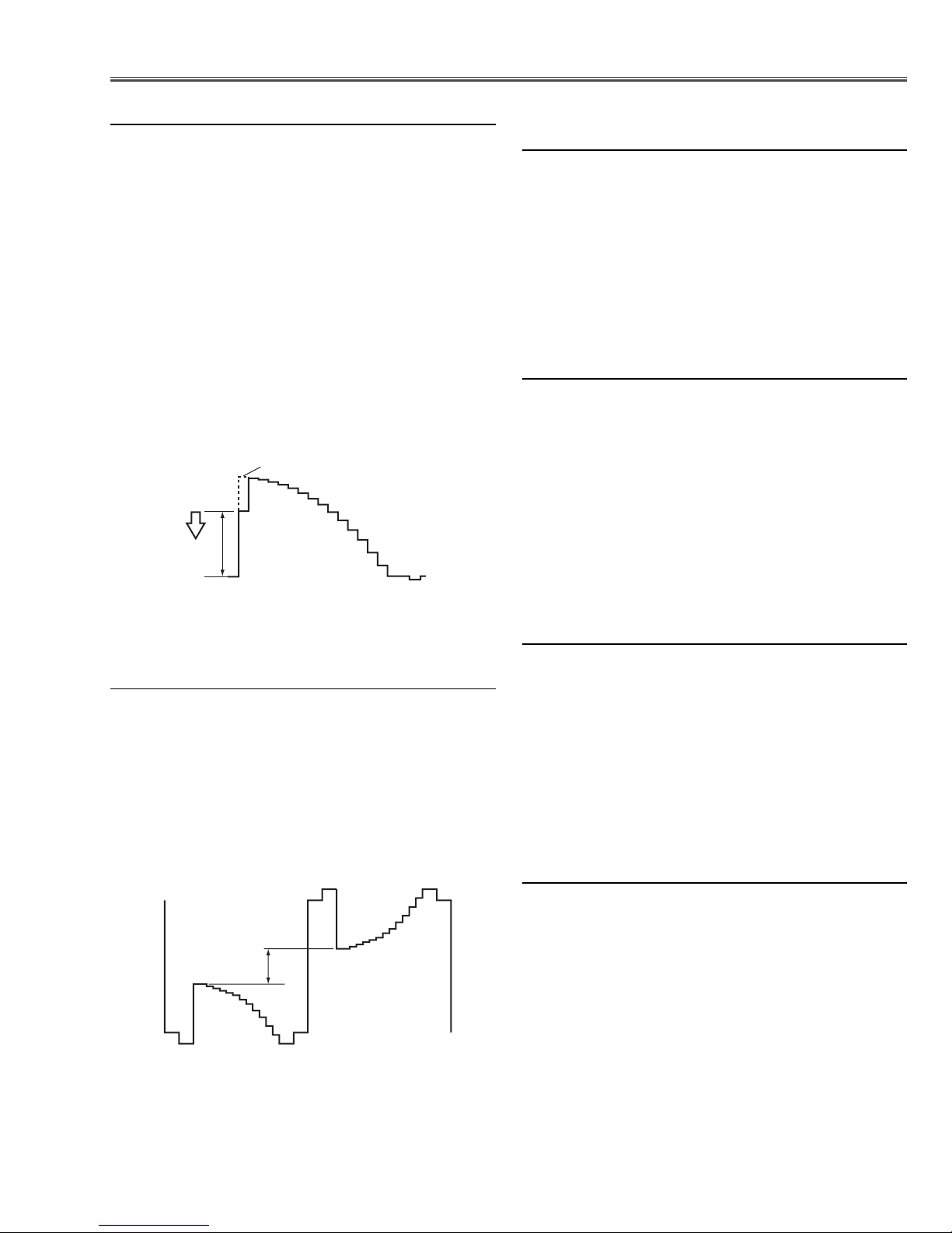
n PC black Level adjustment
1. Receive the 16-step gray scale computer signal with
Input 1 [RGB(Analog)] mode.
2. Enter the service mode.
3. Select group no. “500”, item no. “0” and change data
value to adjust the green noise on the white 0% area
of screen to the first point of the deepest green.
4. Select item no. “1” and change data value to adjust
the blue noise on the white 0% area of screen to the
first point of the deepest blue.
4. Select item no. “2” and change data value to adjust
the red noise on the white 0% area of screen to the
first point of the deepest red.
m PC pedestal adjustment
Electrical Adjustments
(b)
(a)
GND
black level
(a)
black level
-9-
1. Receive the 16-step gray scale composite video signal with Input 3 [Video] mode.
2. Enter the service mode.
3. Connect a digital voltmeter to test point “TPVRB”(+)
and chassis ground (-).
4. Select group no. “5”, item no. “17” and change data
value to adjust the voltage to be 0.70 ±0.02Vdc.
⁄0 Video A/D reference voltage (bottom
side) adjustment
1. Receive the black 0% composite video signal with
Input 3 [Video] mode.
2. Enter the service mode.
3. Select group no. “5”, item no. “11” and change data
value to adjust the green noise on the screen to the
deepest green.
1. Receive the white 100% composite video signal with
Input 3 [Video] mode.
2. Enter the service mode.
3. Select group no. “5”, item no. “18” and change data
value to adjust the magenta noise on the screen to
the deepest magenta.
1. Receive the black 0% composite video signal with
Input 3 [Video] mode.
2. Enter the service mode.
3. Select group no. “5”, item no. “12” and change data
value to adjust the blue noise on the screen to the
deepest blue.
4. Select group no. “5”, item no. “13” and change data
value to adjust the red noise on the screen to the
deepest red.
⁄3 Video Cb/Cr pedestal adjustment
⁄1 Video Y pedestal adjustment
⁄2 Video A/D reference voltage (top
side) adjustment
1. Receive the 16-step gray scale computer signal with
Input 1 [RGB(Analog)] mode.
2. Enter the service mode.
3. Connect an oscilloscope to test point “TP35G”(+)
and chassis ground (-).
4. Select group no. “4”, item no. “3” and change data
value to adjust waveform “a” to be minimum amplitude.
5. Connect an oscilloscope to test point “TP35B”(+)
and chassis ground (-).
6. Select item no. “4” and change data value to adjust
waveform “a” to be minimum amplitude.
7. Connect an oscilloscope to test point “TP35R”(+)
and chassis ground (-).
8. Select item no. “5” and change data value to adjust
waveform “a” to be minimum amplitude.
, PC gain adjustment
1. Receive the 16-step gray scale computer signal with
Input 1 [RGB(Analog)] mode.
2. Enter the service mode.
3. Connect an oscilloscope to test point “TP35G”(+)
and chassis ground (-).
4. Select group no. “4”, item no. “6” and adjust the
amplitude “a” to be 1.5 ±0.1V by changing the Data
value.
. PC signal offset adjustment
Electrical Adjustments
White Level
(a)
white level
(a)
white level
-10-
1. Receive the 16-step gray scale composite video signal with Input 3 [video] mode.
2. Enter the service mode.
3. Connect an oscilloscope to test point “TP35G”(+)
and chassis ground (-).
4. Select group no. “4”, item no. “3” and change data
value to adjust waveform “a” to be minimum amplitude.
5. Connect an oscilloscope to test point “TP35B”(+)
and chassis ground (-).
6. Select item no. “4” and change data value to adjust
waveform “a” to be minimum amplitude.
7. Connect an oscilloscope to test point “TP35R”(+)
and chassis ground (-).
8. Select item no. “5” and change data value to adjust
waveform “a” to be minimum amplitude.
⁄4 Video gain adjustment
1. Receive the black 0% component 480i video signal
with Input 3 [Component] mode.
2. Enter the service mode.
3. Select group no. “5”, item no. “11” and change data
value to adjust the green noise on the screen to the
deepest green.
⁄6 Component Y pedestal adjustment
1. Receive the white 100% component 480i video signal
with Input 3 [Component] mode.
2. Enter the service mode.
3. Select group no. “5”, item no. “18” and change data
value to adjust the magenta noise on the screen to
the deepest magenta.
⁄7 Component A/D reference voltage
(top side) adjustment
1. Receive the black 0% component 480i video signal
with Input 3 [Component] mode.
2. Enter the service mode.
3. Select group no. “5”, item no. “12” and change data
value to adjust the blue noise on the screen to the
deepest blue.
4. Select item no. “13” and change data value to adjust
the red noise on the screen to the deepest red.
⁄8 Component Cb/Cr pedestal adjustment
1. Receive the 16-step gray scale component 480i signal with Input 3 [Component] mode.
2. Enter the service mode.
3. Connect an oscilloscope to test point “TP35G”(+)
and chassis ground (-).
4. Select group no. “4”, item no. “3” and change data
value to adjust waveform “a” to be minimum amplitude.
5. Connect an oscilloscope to test point “TP35B”(+)
and chassis ground (-).
6. Select item no. “4” and change data value to adjust
waveform “a” to be minimum amplitude.
7. Connect an oscilloscope to test point “TP35R”(+)
and chassis ground (-).
8. Select item no. “5” and change data value to adjust
waveform “a” to be minimum amplitude.
⁄9 Component gain adjustment
1. Receive the 16-step gray scale composite video signal with Input 3 [video] mode.
2. Enter the service mode.
3. Connect an oscilloscope to test point “TP35G”(+)
and chassis ground (-).
4. Select group no. “4”, item no. “6” and adjust the
amplitude “a” to be 1.5 ±0.1V by changing the Data
value.
⁄5 Video signal offset adjustment
Electrical Adjustments
White Level
(a)
white level
(a)
white level
White Level
(a)

-11-
1. Receive the black 0% RGB 480p video signal with
Input 2 [RGB] mode.
2. Enter the service mode.
3. Select group no. “5”, item no. “11” and change data
value to adjust the green noise on the screen to the
deepest green.
¤0 RGB G pedestal adjustment
1. Receive the white 100% RGB 480p video signal with
Input 2 [RGB] mode.
2. Enter the service mode.
3. Select group no. “5”, item no. “18” and change data
value to adjust the magenta noise on the screen to
the deepest magenta.
¤1 RGB A/D reference voltage (top side)
adjustment
1. Receive the black 0% RGB 480p video signal with
Input 2 [RGB] mode.
2. Enter the service mode.
3. Select group no. “5”, item no. “12” and change data
value to adjust the blue noise on the screen to the
deepest blue.
4. Select item no. “13” and change data value to adjust
the red noise on the screen to the deepest red.
¤2 RGB B/R pedestal adjustment
1. Receive the 16-step gray scale RGB 480p signal with
Input 2 [RGB] mode.
2. Enter the service mode.
3. Connect an oscilloscope to test point “TP35G”(+)
and chassis ground (-).
4. Select group no. “4”, item no. “3” and change data
value to adjust waveform “a” to be minimum amplitude.
5. Connect an oscilloscope to test point “TP35B”(+)
and chassis ground (-).
6. Select item no. “4” and change data value to adjust
waveform “a” to be minimum amplitude.
7. Connect an oscilloscope to test point “TP35R”(+)
and chassis ground (-).
8. Select item no. “5” and change data value to adjust
waveform “a” to be minimum amplitude.
¤3 RGB gain adjustment
1. Receive the 16-step gray scale computer signal with
Input 1 [RGB(Analog)] mode.
2. Enter the service mode.
3. Project only green light component to the screen.
4. Select group no. “4”, item no. “51” and change data
value to obtain the minimum flicker on the screen.
5. Project only blue light component to the screen.
6. Select item no. “52” and change data value to obtain
the minimum flicker on the screen.
7. Project only red light component to the screen.
8. Select item no. “53” and change data value to obtain
the minimum flicker on the screen.
¤4 Common center adjustment
[PC WHITE BALANCE ADJUSTMENT]
1. Receive the 16-step gray scale computer signal with
Input 1 [RGB(Analog)] mode.
2. Enter the service mode, select group no. “4”, item no.
“7”(Blue) or “8” (Red), and change data values
respectively to make a proper white balance.
[AV WHITE BALANCE ADJUSTMENT]
3. Receive the 16-step gray scale composite video signal with Input 3 [Video] mode.
4. Enter the service mode, select group no. “4”, item no.
“7”(Blue) or “8” (Red), and change data values
respectively to make a proper white balance.
Confirm that the same white balance is obtained in
video and computer input.
¤5 White balance adjustment
If you find the color shading on the screen, please
adjust the white uniformity by using the proper computer and “Color Shading Correction” software supplied
separately. The software can be ordered as follows;
COLOR SHADING CORRECTION SOFTWARE
Ser
vice Parts No. 645 056 6288
or 645 066 7428
NOTE ON WHITE UNIFORMITY
ADJUSTMENT
Electrical Adjustments
White Level
(a)
-12-
Group: 0 TA1370
0 SEP_LEV 3 / 3 / 3 0 ~ 3 YCbCr-1080i,1035i,720p / RGB-1080i,1035i,720p / others
1 YCLP_PHS 0 / 1 / 1 0 or 1 YCbCr-1080i,1035i,720p / RGB-1080i,1035i,720p / others
2 HD_PHASE 37 / 40 / 36 / 37 / 40 / 0 ~ 63 YCbCr-1080i,1035i / 720p / 1080i_50 / RGB-1080i / RGB-720p /
36 / 37 / 37 / 32 RGB-1080i_50 / 575p / 480p / others
3 V_FREQ - - Read only
4H_FREQ - -
5 HD_IN - -
Group: 1 uPD64083
0 NRMD 0 0 ~ 3
1 HDP 4 0 ~ 7
2 CDL 4 0 ~ 7
3DYCOR 4 0 ~ 15 DY detect coring level (Y movement detect coring)
4DYGAIN 15 0 ~ 15 DY detect gain (Y movement detect gain)
5 DCCOR 2 0 ~ 15 DC detect coring level (C movement detect coring)
6 DCGAIN 13 0 ~ 15 DC detect gain (C movement detect gain)
7VAPGAIN 3 0 ~ 15
8VAPINV 2 0 ~ 15
9 YPFT 3 0 ~ 3
10 YPFG 12 0 ~ 15
11 V1PSEL 3 0 ~ 3
12 VEGSEL 3 0 ~ 3
13 CC3N 0 0 or 1
14 SELD2FH 1 0 or 1
15 SELD1FL 1 0 or 1
16 YHCOR 0 0 ~ 3
17 HPLLFG 1 0 or 1
18 PLLFS 1 0 or 1
19 KILR 3 0 ~ 15
20 HSSL 12 0 ~ 15
21 VSSL 3 0 ~ 15
22 BGPS 7 0 ~ 15
23 BGPW 3 0 ~ 15
Group: 2 TB1274AF
0 TINT 32 0 ~ 63
1 SHP_EQ 2 0 ~ 3
2 SHP_FO 2 0 ~ 3
3 SHP_GAIN 11 / 11 / 8 / 6 0 ~ 15 Video NT / PAL,PALM,PALN / SECAM,BW60,BW50 / NT443 /
6 / 9 / 8 / 8 PAL60 / S-Video / YCbCr / Scart
4 Y_OUT_LEVEL 33 / 31 / 32 / 32 / 35 / 0 ~ 63 Video NT / NT443 / PAL,PALM,PALN / PAL60 / SECAM,BW /
0.7V 31 / 31 / 32 / 32 S-Video NT,BW / NT443 / PAL,PALM,PALN / PAL60
32 / 35 / 38 SECAM / YCbCr / Scart
5 C_OUT_LEVEL 25 / 24 / 31 / 25 / 41 / 0 ~ 63 Video NT / NT443 / PAL,PALM,PALN / PAL60 / SECAM,BW /
0.6V 26 / 26 / 32 / 25 / S-Video NT,BW / NT443 / PAL,PALM,PALN / PAL60
42 / 35 / 35 / 35 SECAM / 480i / 575i / Scar t
6 Y_DELAY 5 / 5 / 4 / 4 / 4 / 0 ~ 15 Video NT,BW60 / PAL,PALM,PALN,BW50 / SECAM / NT443 / PAL60
4 / 4 / 3 / 3 / 4 S-Video NT,BW60 / PAL,PALM,PALN,BW50 / SECAM / NT443 / PAL60
7 COL_SYS - - Read Only
8X’TAL - -
9 NOISE_DET - -
10 V_FREQ - -
11 Vert. Std - -
12 CID - -
13 V_SIG - -
14 MVM 0 0 or 1
15 AFC_GAIN 1 0 ~ 3
16 SECAM_GP, SECAM_ID 7 0 ~ 15
17 LPF 1 / 1 0 or 1 Not-Scart / Scart
Group: 3 CXA2151
0MATOUT 0 / 0 / 0 / 2 / 1 0 ~ 3 RGB / YCbCr 480i&575i / YCbCr 480p&575p / YCbCr 1080i&720p / YCbCr 1035i
1 V_TC 0 / 0 / 0 / 0 / 0 ~ 3 RGB-480i,575i / 480p,575p / 720p,1080i / 1035i
0 / 0 / 0 / 0 YCbCr-480i,575i / 480p,575p / 720p,1080i / 1035i
2 HSEP_SEL 0 / 0 / 0 / 0 / 0 or 1 RGB-480i,575i / 480p,575p / 720p,1080i / 1035i
0 / 0 / 0 / 0 YCbCr-480i,575i / 480p,575p / 720p,1080i / 1035i
3 HD_TC 0 / 0 / 0 / 0 / 0 or 1 RGB-480i,575i / 480p,575p / 720p,1080i / 1035i
0 / 0 / 0 / 0 YCbCr-480i,575i / 480p,575p / 720p,1080i / 1035i
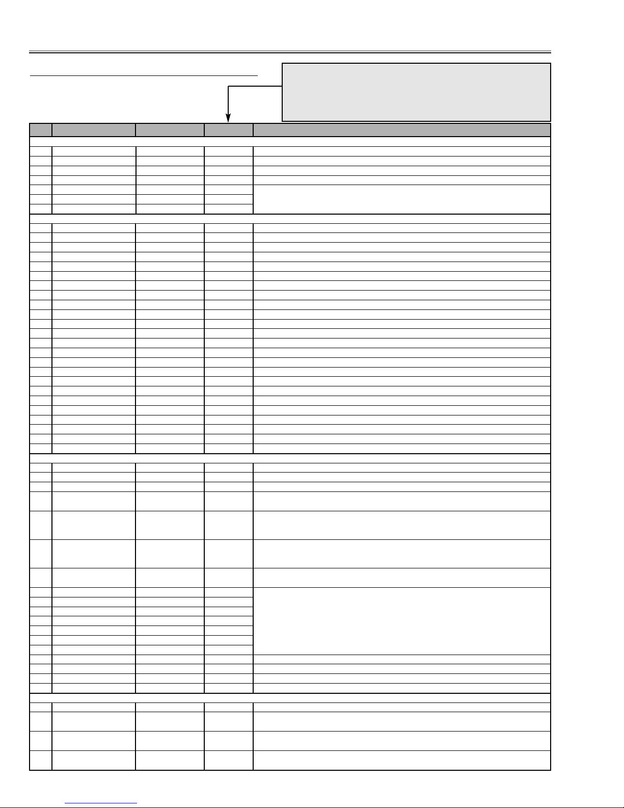
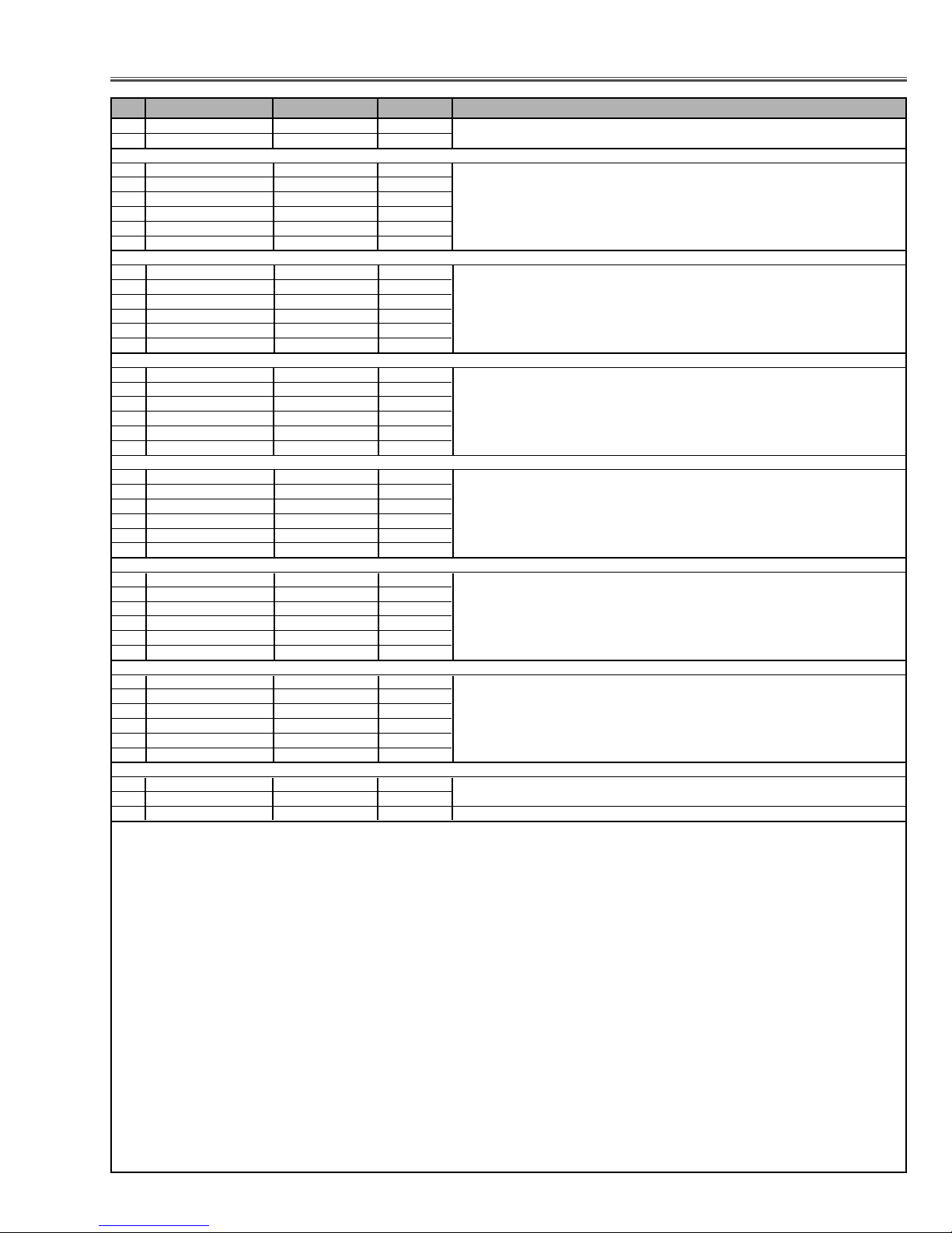
No. Adjustment Item Initial Value Range Input source / Description
Electrical Adjustments
● Service Adjustment Data T
able
These initial values are the reference data written from the CPU
ROM to memory IC when replaced new memory IC. The adjustment items indicated with “✻” are required to readjust following
to the “Electrical adjustments”. Other items should be used with
the initial data value.
-13-
4 HS_MASK 0 / 0 / 0 / 0 / 0 or 1 RGB-480i,575i / 480p,575p / 720p,1080i / 1035i
0 / 0 / 0 / 0 YCbCr-480i,575i / 480p,575p / 720p,1080i / 1035i
5MACRO 1 / 1 / 0 / 0 or 1 RGB-480i,575i / 480p,575p / 720p,1035i,1080i
1 / 1 / 0 YCbCr-480i,575i / 480p,575p / 720p,1035i,1080i
6 CB_GAIN 6 / 6 / 6 / 6 / 6 0 ~ 15 RGB / YCbCr-480i,575i / YCbCr-480p,575p / YCbCr-1080i,720p / YCbCr-1035i
7 CR_GAIN 6 / 6 / 6 / 6 / 6 0 ~ 15 RGB / YCbCr-480i,575i / YCbCr-480p,575p / YCbCr-1080i,720p / YCbCr-1035i
8 Y_GAIN 6 / 6 / 6 / 6 / 6 0 ~ 15 RGB / YCbCr-480i,575i / YCbCr-480p,575p / YCbCr-1080i,720p / YCbCr-1035i
9 GAIN_SEL 1 / 1 0 ~ 3 without RGB Video / RGB Video
Group: 4 PANEL (L3E07070, L3E06110)
0 G_SUB_BRT 0 / 0 0 ~ 1023 PC / DVI, HDCP, AV, RGB-VIDEO White 100% Adjustment
1 B_SUB_BRT 0 / 0 0 ~ 1023
2 R_SUB_BRT 0 / 0 0 ~ 1023
3 G_SUB_GAIN 560 / 560 / 490 / 560 0 ~ 1023 PC / AV, RGB-VIDEO / DVI, HDCP / Component ✻ Gain adjustment [G]
4 B_SUB_GAIN 560 / 560 / 490 / 560 0 ~ 1023 ✻ Gain adjustment [B]
5R_SUB_GAIN 560 / 560 / 490 / 560 0 ~ 1023 ✻ Gain adjustment [R]
6 Standard G_GAMMA SHIFT 512 / 512 0 ~ 1023 PC(A, D) / AV, RGB-VIDEO, HDCP ✻ Gamma signal offset adjustment
7 Standard B_GAMMA SHIFT 512 / 512 0 ~ 1023 ✻ White balance adjustment [B]
8 Standard R_GAMMA SHIFT 512 / 512 0 ~ 1023 ✻ White balance adjustment [R]
9Real/Cinema G_Gamma_ SH -3 / -3 -512 ~ 511 PC(A, D) / AV, RGB-VIDEO, HDCP
10 Real/Cinema B_Gamma_ SH -2 / -2 -512 ~ 511
11 Real/Cinema R_Gamma_ SH 0 / 0 -512 ~ 511
12 H_Crosstalk_R_Center 5 0 ~ 2047
13 H_Crosstalk_G_Center 5 0 ~ 2047
14 H_Crosstalk_B_Center 5 0 ~ 2047
15 P_Ghost_Correction_R 4 0 ~ 2047
16 P_Ghost_Correction_G 4 0 ~ 2047
17 P_Ghost_Correction_B 4 0 ~ 2047
18 R_V-line_Shade_Offset_1 16 0 ~ 31
19 R_V-line_Shade_Offset_2 16 0 ~ 31
20 R_V-line_Shade_Offset_3 16 0 ~ 31
21 R_V-line_Shade_Offset_4 16 0 ~ 31
22 R_V-line_Shade_Offset_5 16 0 ~ 31
23 R_V-line_Shade_Offset_6 16 0 ~ 31
24 G_V-line_Shade_Offset_1 16 0 ~ 31
25 G_V-line_Shade_Offset_2 16 0 ~ 31
26 G_V-line_Shade_Offset_3 16 0 ~ 31
27 G_V-line_Shade_Offset_4 16 0 ~ 31
28 G_V-line_Shade_Offset_5 16 0 ~ 31
29 G_V-line_Shade_Offset_6 16 0 ~ 31
30 B_V-line_Shade_Offset_1 16 0 ~ 31
31 B_V-line_Shade_Offset_2 16 0 ~ 31
32 B_V-line_Shade_Offset_3 16 0 ~ 31
33 B_V-line_Shade_Offset_4 16 0 ~ 31
34 B_V-line_Shade_Offset_5 16 0 ~ 31
35 B_V-line_Shade_Offset_6 16 0 ~ 31
36 V-line_Shade_Correction_R0 3 0 ~ 255
37 V-line_Shade_Correction_R1 2 0 ~ 255
38 V-line_Shade_Correction_R2 0 0 ~ 255
39 V-line_Shade_Correction_R3 255 0 ~ 255
40 V-line_Shade_Correction_R4 0 0 ~ 255
41 V-line_Shade_Correction_G0 3 0 ~ 255
42 V-line_Shade_Correction_G1 2 0 ~ 255
43 V-line_Shade_Correction_G2 0 0 ~ 255
44 V-line_Shade_Correction_G3 255 0 ~ 255
45 V-line_Shade_Correction_G4 0 0 ~ 255
46 V-line_Shade_Correction_B0 3 0 ~ 255
47 V-line_Shade_Correction_B1 2 0 ~ 255
48 V-line_Shade_Correction_B2 0 0 ~ 255
49 V-line_Shade_Correction_B3 255 0 ~ 255
50 V-line_Shade_Correction_B4 0 0 ~ 255
51 G_LCCOM 163 0 ~ 255 G Common Center Adjustment ✻ Common center adjustment [G]
52 B_LCCOM 163 0 ~ 255 B Common Center Adjustment ✻ Common center adjustment [B]
53 R_LCCOM 163 0 ~ 255 R Common Center Adjustment ✻ Common center adjustment [R]
54 G_V_COM_CEILING 0 -128 ~ 127 G Common Center Adjustment ( Difference between Normal mode and Ceiling mode )
55 B_V_COM_CEILING 0 -128 ~ 127 G Common Center Adjustment ( Difference between Normal mode and Ceiling mode )
56 R_V_COM_CEILING 0 -128 ~ 127 G Common Center Adjustment ( Difference between Normal mode and Ceiling mode )
Group: 5 DAC
0 REF_G 105 0 ~ 255 DAC1 ✻ Black Level Adjustment [G]
1 REF_B 105 0 ~ 255 DAC1 ✻ Black Level Adjustment [B]
2 REF_R 105 0 ~ 255 DAC1 ✻ Black Level Adjustment [R]
3 NRSB 155 0 ~ 255 DAC1 NRSB ✻ NRS adjustment (High)
4 NRSA 100 0 ~ 255 DAC1 NRSA
✻ NRS adjustment (Low)
Electrical Adjustments
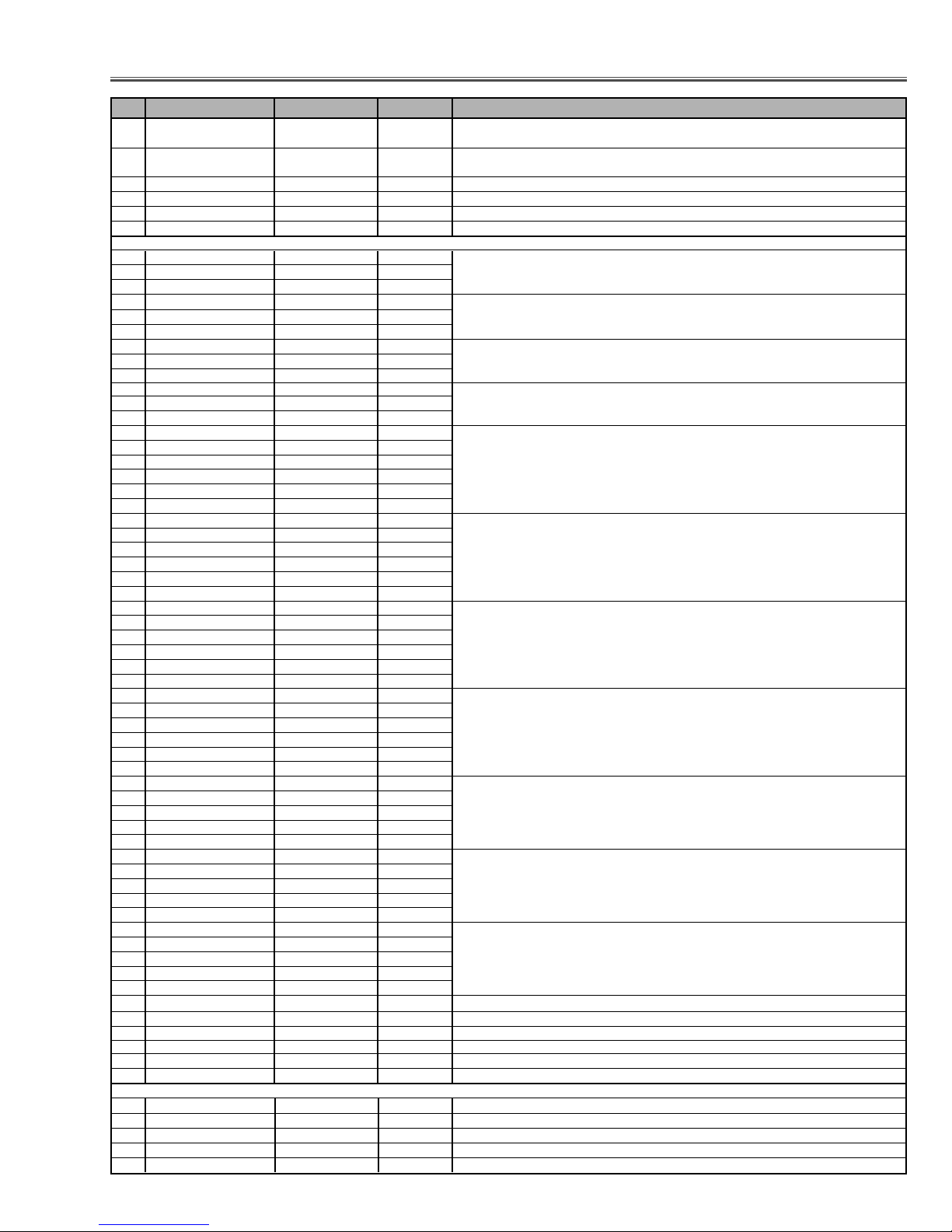
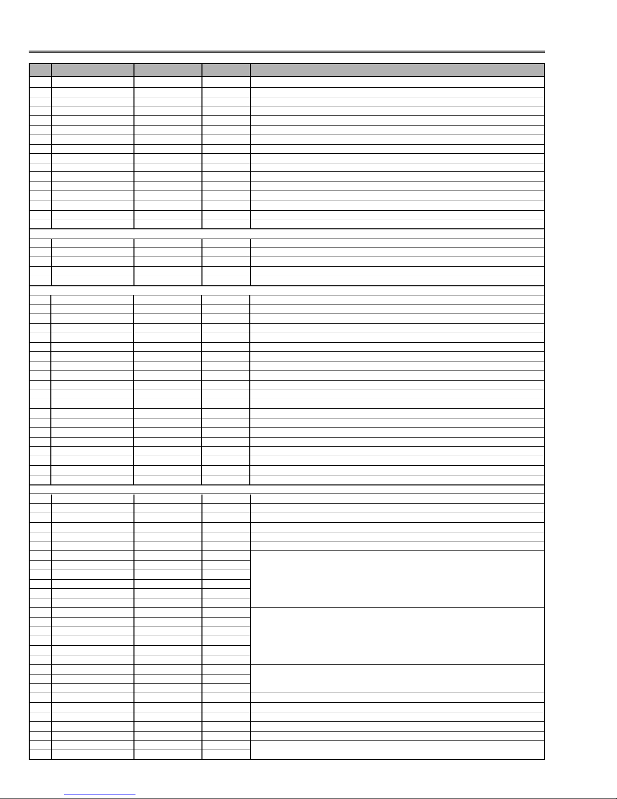
No. Adjustment Item Initial Value Range Input source / Description
-14-
5 G_V1 134 0 ~ 255 DAC2 ✻ Video center adjustment [G]
6 B_V1 134 0 ~ 255 DAC2 ✻ Video center adjustment [B]
7 R_V1 134 0 ~ 255 DAC2 ✻ Video center adjustment [R]
8 G_V2 154 0 ~ 255 DAC2 ✻ Video center adjustment [G]
9 B_V2 154 0 ~ 255 DAC2 ✻ Video center adjustment [B]
10 R_V2 154 0 ~ 255 DAC2 ✻ Video center adjustment [R]
11 G_CLMP 125 / 210 / 210 / 210 0 ~ 255 PC(not RGB Video) / RGB Video / Video, SCART / Component ✻ Y/G pedestal adjustment
12 B_CLMP 181 / 160 / 220 / 225 0 ~ 255 PC(not RGB Video) / RGB Video / Video, SCART / Component ✻ Cb/B pedestal adjustment
13 R_CLMP 184 / 160 / 220 / 225 0 ~ 255 PC(not RGB Video) / RGB Video / Video, SCART / Component ✻ Cr/R pedestal adjustment
14 SGAIN + - 0 ~ 255
15 SGAIN - 128 0 ~ 255
16 LF_LEV 255 / 255 / 255 / 0 / 0 0 ~ 255 SCART / RGB-480i,575i / YCbCr-480i,575i / VIDEO,S-VIDEO / Others
17 DAC_VRB 35 0 ~ 255 ✻ A/D reference voltage bottom adjustment
18 DAC_GY 110 / 115 / 115 0 ~ 255 Composite, SCART / Component / RGB Video ✻ A/D reference voltage top adjustment
19 DAC_BCB 110 / 115 / 115 0 ~ 255 Composite, SCART / Component / RGB Video
20 DAC_RCR 110 / 115 / 115 0 ~ 255 Composite, SCART / Component / RGB Video
Group: 6 TC90A69F
0Y-EQ_GAIN 3 0 ~ 3
1Y-EQ_N_C_LIM 3 0 ~ 3
2V-ENH_GAIN 4 0 ~ 7
3 V_ENH_CORING 2 0 ~ 3
4 NTSC443_SW 1 0 ~ 1 0 : NTSC4.43 1 : PAL60 (Available for NTSC4.43)
Group: 10 Option
0 Lamp Time Monitor - 0 ~ 8738 Read only
1 RS232C Baudrate 0 0 ~ 1 0: 19200bps 1: 9600bps
2 Shootout Mode 0 0 ~ 1 0: Disable 1: Enable
3 Cooling Time 3 0 ~ 15 Set cooling period, 1: 30 sec. 3: 90 sec. 15: 450 sec. 0: continuos
4Hi-Land SW 0 0 ~ 1 0: Normal 1: Highland mode (Fan spin speed max.)
5V-Douki SW 0 0 ~ 1 0: Synchronized Vertical 1: non-synchronized Vertical
6 Lamp Total Time - 0 ~ 65535 Read only
7 Net Board RESET 1 0 ~ 1 0: Disable 1: Enable
8Keystone Option 0 0 ~ 1 0: Maximum correction (fix) 1: Changeable for Input signal
9 Syukka SW 0 0 ~ 10 Set 10 to Shipping Condition
10 Color Shading SW 1 0 ~ 1 0: OFF 1: ON
11 RC Enable/Disable 0 0 ~ 3 0: Both enable 1: Front Disable 2: Rear Disable 3: Both Disable
12 Lamp Dim Level 15 0 ~ 15 0: the darkest 1: the brightest
13 Lamp Warning Time 1500 0 ~ 65535 Unit = hour
14 Forced NOBRAND 0 0 ~ 1 0: Normal 1: No brand
15 Forced Video Mute Off 0 0 ~ 1 0: Video Mute ON 1: Video Mute OFF
16 ANZEN FAN Control Fix SW 0 0 ~ 4 0: Normal 1: Normal min. 2: Normal max 3: Eco min. 4: Eco max
17 DJTR_SW - - Not used
18 HDCP Option 0 0 ~ 3 0: XGA 1: Not XGA
19 HDCP Reset 0 0 ~ 10 Set 10 and write EDID Data for HDCP
Group: 11 FAN (Fan Control)
0FAN_TEMP_A_WARNING 460 30 ~ 1000 Temperature to judge abnormal A (Not memorized) Inside projector
1FAN_TEMP_B_WARNING 800 30 ~ 1000 Temperature to judge abnormal A (Not memorized) Lamp
2FAN_TEMP_C_WARNING 510 30 ~ 1000 Temperature to judge abnor mal A (Not memorized) LCD Panel
3FAN_TEMP_B-A_WARNING 520 0 ~ 1000
4FAN_TEMP_C-A_WARNING 200 0 ~ 1000
5FAN_CONTROL_SW 0 0 or 1 0: Auto-control all Fans 1: Manual control all Fans
6FAN1 Manual Out 1350 0 ~ 2000 These are effective when FAN_CONTROL_SW is set to "1".
7FAN2 Manual Out 1350 0 ~ 2000
8FAN4 Manual Out 1350 0 ~ 2000
9FAN5 Manual Out 1350 0 ~ 2000
10 FAN6 Manual Out 1350 0 ~ 2000
11 FAN7 Manual Out 1350 0 ~ 2000
12 FAN1 Now Out - Read only Reading voltage of each Fan
13 FAN2 Now Out -
14 FAN4 Now Out -
15 FAN5 Now Out -
16 FAN6 Now Out -
17 FAN7 Now Out -
18 Temp Monitor A - - Read only
19 Temp Monitor B - -
20 Temp Monitor C - -
21 Pressure Monitor - - Read only
22 FAN_BALLAST_SW 0 0 or 1 Fan control depend on Ballast Output Voltage 0: OFF 1: ON
23 Service Target MODE -1 -1 ~ 3 -1: Current Mode 0: Normal Mode 1: Eco Mode
24 Service Target FAN 0 0 ~ 5 Service target 0: FAN1 1: FAN2 2: FAN4 3: FAN5 4: FAN6 5: FAN7 ✻ Fan adjustment [Setting]
25 Control Switch 0 Control Switch for the operated Fan 0: Auto 1: Manual
26 Temp Source Range High 400 Control range of Temperature for Temperature Sensor A
27 Temp Source Range Low 330
Electrical Adjustments
No. Adjustment Item Initial Value Range Input source / Description
-15-
28 Temp Fan-Out Range High 1350 / 1000 Control range of Fan control voltage by Temperature Sensor A
29 Temp Fan-Out Range Low 780 / 700 / 1000
30 Diff (UP)Src Range High 180 Difference of temperature between temp-A and temp-C for Fan additional voltage (upward)
31 Diff (UP)Src Range Low 150
32 Diff(DWN)Src Range High 80 Difference of temperature between temp-A and temp-C for Fan additional voltage (downward)
33 Diff(DWN)Src Range Low 60
34 Press Source Range Low Control range of Pressure Sensor
35 Press Source Range High
36 Press FanAdd Range High 0 Control range of Fan additional voltage by Pressure sensor
37 Press FanAdd Range Low 500
38 Ceiling-Add Fan additional voltage when ceiling
39 Fan Out Limit Volt MAX 1400 Limit voltage of current Fan output voltage
40 Fan Out Limit Volt MIN. 650
41 Fan Out Limit DAC MAX 0 ~ 255 Limit of DAC output for current Fan ✻ Fan a djustment [max.]
42 Fan Out Limit DAC MIN. 0 ~ 255 ✻ Fan adjustment [min.]
43 Manual Out 0 ~ 2000 Output voltage of current Fan at manual mode
44 Now Out - Reading voltage of current Fan
Group: 12 PC Real / AV Cinema
0 PC Real Contrast 32 0 ~ 63
1 PC Real Brightness 32 0 ~ 63
2 PC Real Color 32 0 ~ 63
3 PC Real Tint 32 0 ~ 63
4 PC Real Red 32 0 ~ 63
5 PC Real Green 30 0 ~ 63
6PC Real Blue 29 0 ~ 63
7 PC Real Sharpness 0 0 ~ 31
8 PC Real Gamma 8 0 ~ 15
9 PC Real N.R. 1 0 ~ 2
10 PC Real PROGRESSIVE 1 0 or 1
11 AV Cinema Contrast 32 0 ~ 63
12 AV Cinema Brightness 32 0 ~ 63
13 AV Cinema Color 32 0 ~ 63
14 AV Cinema Tint 32 0 ~ 63
15 AV Cinema Red 32 0 ~ 63
16 AV Cinema Green 30 0 ~ 63
17 AV Cinema Blue 29 0 ~ 63
18 AV Cinema Sharpness 15 0 ~ 31
19 AV Cinema Gamma 8 0 ~ 15
20 AV Cinema N.R. 1 0 ~ 2
21 AV Cinema PROGRESSIVE 1 0 or 1
Group: 20 IP_Converter
0IMAGE_IN_FUNC_POL 0/0/0/0/0/ 0/0/0/0/0 0 or 1 000-b4 (reg 0) NTSC / PAL / 480p / 575p / 1035i / 1080i / 1080i50 / 720p / 480i / 575i
1IMAGE_IN_HD_SEL 1/1/1/1/1/ 1/1/1/1/1 0 or 1 000-b3
2IMAGE_IN_HD_POL 1/1/1/1/1/ 1/1/1/1/1 0 or 1 000-b2
3IMAGE_IN_VD_POL 1/1/1/1/1/ 1/1/1/1/1 0 or 1 000-b1
4IMAGE_IN_LPF_SEL 0/0/0/0/0/ 0/0/0/0/0 0 or 1 000-b0
5IMAGE_OUT_CLK_POL 0/0/0/0/0/ 0/0/0/0/0 0 or 1 001-b5
6IMAGE_OUT_HD_POL 0/0/0/0/0/ 0/0/0/0/0 0 or 1 001-b4
7IMAGE_OUT_VD_POL 0/0/0/0/0/ 0/0/0/0/0 0 or 1 001-b3
8IMAGE_OUT_CS_SEL 0/0/0/0/0/ 0/0/0/0/0 0 or 1 001-b2
9IMAGE_OUT_DEMUX 1/1/1/1/1/ 1/1/1/1/1 0 or 1 001-b1
10 IMAGE_OUT_THROUGH 0/0/1/1/0/ 0/0/1/0/0 0 or 1 001-b0
11 IMAGE_IN_TOTAL_H Same as G510 - G517 0 ~ 2047 002 / 003 Same as G510 - G517 Read only
12 IMAGE_IN_START_H 190/ 200/ 184/ 208/ 136/ 0 ~ 2047 004 / 005
137/ 96/ 237/ 190/ 205
13 IMAGE_IN_SIZE_H 9/10/9/9/8/ 8/10/10/9/10 0 ~ 15 006 Read only
14 IMAGE_IN_START_V, 10 / 15 / 32 / 26 / 13/ 0 ~ 1023 007 / 008
10 / 10 / 20 / 10 / 16
15 IMAGE_IN_SIZE_V, 250 / 295 / 490 / 0 ~ 1023 009 / 010
545 / 545 / 545 / 545/
725 / 250 / 296
16 CLAMP_H, 100 / 130 / 112 / 123 / 0 ~ 2047 011 / 012 NTSC / PAL / Comp480p / Comp575p /
56 / 58 / 107 / 115 / Comp1035i / Comp1080i,1080i50 / Comp720p / Comp480i /
130 / 113 / 123 / 56 / Comp575i / RGB480p / RGB575p / RGB1035i /
58 / 107 / 115 / 130 RGB1080i,1080i50 / RGB720p / RGB480i / RGB575i
17 CLAMP_L, 140 / 160 / 142 / 158 / 0 ~ 2047 013 / 014
81 / 83 / 161 / 145 /
160 / 143 / 158 / 81 /
83 / 161 / 145 / 160
18 IMAGE_OUT_DELAY_H, 0 ~ 2047 015 / 016 (reg 2) NTSC / PAL / 480p /
- Read only 575p / 1035i / 1080i,1080i50 /
720p / 480i / 575i
Electrical Adjustments
No. Adjustment Item Initial Value Range Input source / Description
-16-
19 SYNC_OUT_DELAY_H, 0 ~ 2047 017 / 018
-Read only
20 SYNC_OUT_DELAY_V, - 0 ~ 2047 019 / 020
Read only
21 IMAGE_OUT_START_H, 0 Set 0 021 / 022
22 IMAGE_OUT_END_H, 2047 Set 2047 023 / 024
23 IMAGE_OUT_START_V, 0/ 0/ 0/ 0/ 0/ 0/ 0/ 0/ 0 0 ~ 2047 025 / 026 + F440
24 IMAGE_OUT_END_V, 517 / 618 / 1038 / 0 ~ 2047 027 / 028
1250 / 1119 / 1119 /
1490 / 517 / 618
25 G_Y_IN_OS, 0 / 0 0 ~ 255 029 (reg 3) Not_RGB / RGB
26 B_CB_IN_OS, 128 / 0 0 ~ 255 030
27 R_CR_IN_OS, 128 / 0 0 ~ 255 031
28 G2Y, 256 / 150 0 ~ 1023 032 / 033 (reg 4) Not_RGB / RGB
29 B2Y, 0 / 29 0 ~ 1023 034 / 035
30 R2Y, 0 / 77 0 ~ 1023 036 / 037
31 G2CB, 0 / 939 0 ~ 1023 038 / 039
32 B2CB, 256 / 128 0 ~ 1023 040 / 041
33 R2CB, 0 / 983 0 ~ 1023 042 / 043
34 G2CR, 0 / 917 0 ~ 1023 044 / 045
35 B2CR, 0 / 1003 0 ~ 1023 046 / 047
36 R2CR, 256 / 128 0 ~ 1023 048 / 049
37 HUE_M, 37 / 35 0 ~ 255 050
38 GAIN_M, 0 / 0 0 ~ 127 051
39 DG_M_R, 0 / 0 0 ~ 63 052 (reg 4) Not_RGB / RGB
40 HUE_R, 77 / 73 0 ~ 255 053
41 GAIN_R, 0 / 0 0 ~ 127 054
42 DG_R_Y, 0 / 0 0 ~ 63 055
43 HUE_Y, 121 / 124 0 ~ 255 056
44 GAIN_Y, 0 / 0 0 ~ 127 057
45 DG_Y_G, 0 / 0 0 ~ 63 058
46 HUE_G, 165 / 163 0 ~ 255 059
47 GAIN_G, 0 / 0 0 ~ 127 060
48 DG_G_C, 0 / 0 0 ~ 63 061
49 HUE_C, 205 / 201 0 ~ 255 062
50 GAIN_C, 0 / 0 0 ~ 127 063
51 DG_C_B, 0 / 0 0 ~ 63 064
52 HUE_B, 249 / 252 0 ~ 255 065
53 GAIN_B, 0 / 0 0 ~ 127 066
54 DG_B_M, 0 / 0 0 ~ 63 067
55 DNR_Y_NOISE_TH, 8 / 8 0 ~ 255 068 (reg 5) DNR-OFF / DNR-ON
56 DNR_Y_SENSE, 0 / 6 0 ~ 15 069
57 DNR_Y_MOTION_TH, 0 / 0 0 ~ 255 070
58 DNR_Y_MOTION_SLOPE, 4 / 4 0 ~ 7 071
59 DNR_Y_MOTION_F2_F0, 0 / 0 0 ~ 3 072
60 DNR_Y_MOTION_F4_F2, 3 / 3 0 ~ 3 073
61 DNR_C_NOISE_TH, 8 / 8 0 ~ 255 074
62 DNR_C_SENSE, 0 / 8 0 ~ 255 075
63 DNR_C_MOTION_TH, 0 / 0 0 ~ 255 076
64 DNR_C_MOTION_SLOPE, 4 / 4 0 ~ 7 077
65 DNR_C_MOTION_F2_F0, 0 / 0 0 ~ 3 078
66 DNR_C_MOTION_F4_F2, 3 / 3 0 ~ 3 079
67 IP_DEBUG, 0 / 0 / 0 0 ~ 7 080 (reg 6) IP-ON=NTSC,PAL,1035i,1080i,1080i50 /
68 IP_CTL_Y, 0 / 1 / 1 0 or 1 081-1 IP-ON&OFF=720p,480p,575p /
69 IP_CTL_C, 1 / 1 / 1 0 or 1 081-0 IP-OFF=NTSC,PAL,1035i,1080i,1080i50
70 IP_DIR, 10 / 0 / 0 0 ~ 15 082 (reg 7) IP-ON=NTSC,PAL /
71 IP_VAR_GAI, 8 / 0 / 0 0 ~ 15 083 IP-ON=1035i,1080i,1080i50 / IP-ON&OFF=720p,480p,575p /
72 IP_BPF_CORR, 4 / 0 / 0 0 ~ 255 084 IP-OFF=NTSC,PAL,1035i,1080i,1080i50
73 IP_BPF_GAIN, 32 / 0 / 0 0 ~ 63 085
74 IP_REL_H_GAIN, 63 / 0 / 0 0 ~ 63 086
75 IP_REL_V_GAIN, 63 / 0 / 0 0 ~ 63 087
76 MOTION_LPF_SEL, 7/ 7/ 7/ 7/ 7/ 7/ 7/ 7 0 ~ 7 088 (reg 8) DNR-ON=NTSC,PAL / DNR-OFF=NTSC,PAL / 1035i,1080i,1080i50 / 720p,480p,575p /
77 MOTION_TH_MIN., 8/ 8/ 8/ 8/ 22/ 22/ 22/ 22 0 ~ 255 089 L2&&DNR-ON =NT,PAL/L2&&DNR-OFF=NT,PAL/L2=1035i,1080i,1080i50/L2=720p,480p,575p
78 MOTION_TH_MAX, 16 / 16 / 16 / 16 / 0 ~ 255 090
38 / 38 / 38 / 38
79 MOTION_TH_DL, 8/ 12/ 8/ 8/ 8/ 12/ 8/ 8 0 ~ 255 091
80 MOTION_WEIGHT_0, 9/ 9/ 9/ 9/ 9/ 9/ 9/ 9 0 ~ 15 092
81 MOTION_WEIGHT_1, 8/ 8/ 8/ 8/ 8/ 8/ 8/ 8 0 ~ 15 093
82 MOTION_WEIGHT_2, 7/ 7/ 7/ 7/ 7/ 7/ 7/ 7 0 ~ 15 094
83 MOTION_WEIGHT_3, 6/ 6/ 6/ 6/ 6/ 6/ 6/ 6 0 ~ 15 095
84 MOTION_WEIGHT_4, 5/ 5/ 5/ 5/ 5/ 5/ 5/ 5 0 ~ 15 096
85 MOTION_WEIGHT_5, 4/ 4/ 4/ 4/ 4/ 4/ 4/ 4 0 ~ 15 097
No. Adjustment Item Initial Value Range Input source / Description
Electrical Adjustments
-17-
86 MOTION_WEIGHT_6, 3/ 3/ 3/ 3/ 3/ 3/ 3/ 3 0 ~ 15 098
87 MOTION_WEIGHT_7, 2/ 2/ 2/ 2/ 2/ 2/ 2/ 2 0 ~ 15 099
88 MOTION_WEIGHT_8, 1/ 1/ 1/ 1/ 1/ 1/ 1/ 1 0 ~ 15 100
89 MOTION_SUM_0, 20/ 20/ 0/ 0/ 20/ 20/ 0/ 0 0 ~ 1023 101
90 MOTION_SUM_1, 32/ 32/ 9/ 9/ 32/ 32/ 9/ 9 0 ~ 1023 103
91 MOTION_SUM_2, 86/ 86/ 0/ 0/ 86/ 86/ 0/ 0 0 ~ 1023 105
92 MOTION_SUM_3, 110 / 110 / 63 / 63 / 0 ~ 1023 107
110 / 110 / 63 / 63
93 PEAK_V_LPF_SEL, 1 0 or 1 109 (reg 9) fix
94 PEAK_V_CORR, 0 0 ~ 255 110
95 PEAK_V_GAIN, - 0 ~ 63 111 Read only
96 PEAK_V_GAIN_TH, 0 0 ~ 255 112
97 PEAK_V_GAIN_SLOPE, 0 0 ~ 7 113
98 PEAK_V_MAX, 255 0 ~ 255 114
99 TI_Y_TH_MIN., 1 0 ~ 255 115
100 TI_Y_TH_MAX, 255 0 ~ 255 116
101 TI_Y_CORR, 1 0 ~ 255 117
102 TI_Y_GAIN, 1 0 ~ 63 118
103 TI_Y_GAIN_TH, 0 0 ~ 255 119
104 TI_Y_GAIN_SLOPE, 0 0 ~ 7 120
105 TI_Y_GAIN_SEL, 1 0 ~ 7 121
106 TI_C_TH_MIN., 0 0 ~ 255 122
107 TI_C_TH_MAX, 0 0 ~ 255 123
108 TI_C_CORR, 0 0 ~ 255 124
109 TI_C_GAIN, 0 0 ~ 63 125 (reg 9) fix
110 TI_C_GAIN_TH, 0 0 ~ 7 126
111 TI_C_GAIN_SLOPE, 0 0 ~ 7 127
112 TI_C_GAIN_SEL, 0 0 ~ 7 128
113 PEAK_H_BPF_SEL, 0 / 1 0 ~ 3 129 (reg A) NTSC,PAL,480p,575p / 720p,1035i,1080i,1080i50
114 PEAK_H_CORR, 3 / 0 0 ~ 255 130
115 PEAK_H_GAIN, - / - 0 ~ 63 131
116 PEAK_H_GAIN_TH, 0 / 0 0 ~ 255 132
117 PEAK_H_GAIN_SLOPE, 2 / 2 0 ~ 7 133
118 PEAK_H_GAIN_SEL, 1 / 1 0 ~ 3 134
119 PEAK_H_MAX, 255 / 255 0 ~ 255 135
120 Y2G, - / - 0 ~ 1023 136 / 137 (reg B) NTSC,PAL,480p,575p / 1035i,1080i,1080i50,720p
121 CB2G, - / - 0 ~ 1023 138 / 139
122 CR2G, - / - 0 ~ 1023 140 / 141
123 Y2B, - / - 0 ~ 1023 142 / 143
124 CB2B, - / - 0 ~ 1023 144 / 145
125 CR2B, - / - 0 ~ 1023 146 / 147
126 Y2R, - / - 0 ~ 1023 148 / 149
127 CB2R, - / - 0 ~ 1023 150 / 151
128 CR2R, - / - 0 ~ 1023 152 / 153
129 G_Y_OUT_OS, 0 0 ~ 255 154 (reg C) fix
130 G_Y_OUT_MIN., 0 0 ~ 255 155
131 G_Y_OUT_DC, 0 0 ~ 255 156
132 G_Y_OUT_MAX, 255 0 ~ 255 157
133 B_CB_OUT_OS, 0 0 ~ 255 158
134 B_CB_OUT_MIN., 0 0 ~ 255 159
135 B_CB_OUT_DC, 0 0 ~ 255 160
136 B_CB_OUT_MAX, 255 0 ~ 255 161
137 R_CR_OUT_OS, 0 0 ~ 255 162
138 R_CR_OUT_MIN., 0 0 ~ 255 163
139 R_CR_OUT_DC, 0 0 ~ 255 164
140 R_CR_OUT_MAX, 255 0 ~ 255 165
141 CINEMA_START_H, 0 / 0 / 0 0 ~ 255 166 (reg D) IP-ON=NTSC / IP-ON=NTà»äO / IP-OFF
142 CINEMA_SIZE_H, 160 / 0 / 0 0 ~ 255 167
143 CINEMA_START_V, 1 / 0 / 0 0 ~ 255 168
144 CINEMA_SIZE_V, 60 / 0 / 0 0 ~ 255 169
145 CINEMA_MOTION_TH, 16 / 0 / 0 0 ~ 255 170
146 CINEMA_DET_TH, 384 / 0 / 0 0 ~ 65535 171 / 172
147 CINEMA_DET_FIELD, 7 / 0 / 0 0 ~ 7 173
148 CINEMA_CTL_SWAP, 20 / 0 / 0 0 ~ 31 174
149 CINEMA_CTL_Y, 0 / 1 / 1 0 or 1 175-1
150 CINEMA_CTL_C, 1 / 1 / 1 0 or 1 175-0
151 EXT_CINEMA_DET, 0 / 0 / 0 0 or 1 176-2
152 EXT_CINEMA_MODE, 0 / 0 / 0 0 or 1 176-1
153 EXT_CINEMA_SWAP, 0 / 0 / 0 0 or 1 176-0
154 STINT 0 / 0 / 0 0 ~ 31 177 (reg E) without RGB = NTSC,PAL,480p,575p / without RGB = 720p,1035i,1080i,1080i50 / RGB
155 SCOL 140 / 140 / 180 0 ~ 255 178
156 CB2B_STD 454 / 454 / 454 0 ~ 1023 179 / 180
No. Adjustment Item Initial Value Range Input source / Description
Electrical Adjustments
-18-
157 CR2B_STD 0 / 0 / 0 0 ~ 1023 181 / 182
158 CB2R_STD 0 / 0 / 0 0 ~ 1023 183 / 184
159 CR2R_STD 359 / 359 / 359 0 ~ 1023 185 / 186
160 CB2G_STD 1015 / 105 / 1015 0 ~ 1023 187 / 188
161 CR2G_STD 842 / 842 / 842 0 ~ 1023 189 / 190
162 S_SHP 8 / 10 / 0 0 ~ 63 191
Group: 21 IP (MB40C348)
0 V_AMP 0 0 or 1 adr0-2
1 DSEL 1 0 or 1 adr0-1
2CE00 or 1 adr0-0
3 COUNTER_W 64 0 ~ 4095 adr1,adr2(3-0)
4 ADC_OUT 0 0 or 1 adr3-7
5HSYNC_POL 1 0 or 1 adr3-6
6CLK_DELAY 0 0 ~ 63 adr3(5-0)
7 DSYNC_DELAY 1 0 ~ 3 adr4(7-6)
8 ADCLK_B 1 0 or 1 adr4-5
9 ADCLK_A 1 0 or 1 adr4-4
10 DSYNC_B 1 0 or 1 adr4-3
11 DSYNC 1 0 or 1 adr4-2
12 CLK_B 1 0 or 1 adr4-1
13 CLK 1 0 or 1 adr4-0
14 DIVIDER 0 0 ~ 3 adr5(7-6)
15 VCO_CHG 0 0 or 1 adr5-5
16 CURRENT 0 0 or 3 adr5(4-3)
17 counter 1 0 or 1 adr5-2
18 out_clk 0 0 or 1 adr5-1
19 clk_chb 1 0 or 1 adr5-0
Group: 22 ICS1523
0ICS_R0_EnDLS 0/ 0/ 0/ 0/ 0/ 0/ 0/ 0 0 ~ 1 R0
1ICS_R0_EnPLS 1/ 1/ 1/ 1/ 1/ 1/ 1/ 1 0 ~ 1 NTSC & 480i / PAL & SECAM & 525i / 1035i / 1080i60 / 1080i50 / 720p / 480p / 575p
2 ICS_R0_Func_Sel 0/ 0/ 0/ 0/ 0/ 0/ 0/ 0 0 ~ 1
3ICS_R0_Fbk_Sel 0/ 0/ 0/ 0/ 0/ 0/ 0/ 0 0 ~ 1
4ICS_R0_Fbk_Pol 0/ 0/ 0/ 0/ 0/ 0/ 0/ 0 0 ~ 1
5 ICS_R0_Ref_Pol 1/ 1/ 1/ 1/ 1/ 1/ 1/ 1 0 ~ 1
6 ICS_R0_PD_Pol 1/ 1/ 1/ 1/ 1/ 1/ 1/ 1 0 ~ 1
7ICS_R0_Pden 0/ 0/ 0/ 0/ 0/ 0/ 0/ 0 0 ~ 1
8 ICS_R1_PSD 2/ 2/ 0/ 0 0/ 0/ 0/ 0 0 ~ 3 R1 (Left Data : Progressive = ON , Right Data : Progressive = OFF)
9 ICS_R1_PFD 6/ 6/ 6/ 6 6/ 5/ 5/ 5 0 ~ 7 NTSC & 480i / PAL & SECAM & 525i / 1035i / 1080i60 /1080i50 / 720p / 480p / 575p
10 ICS_R3_FBD 2600/ 2654/ 2458/ 2458 0 ~ 8191 R3_R2
2866/ 1343/ 1273/ 1276 NTSC & 480i / PAL & SECAM & 525i / 1035i / 1080i60 / 1080i50 / 720p / 480p / 575p
11 ICS_R4_Fil_Sel 0 0 ~ 1 R4
12 ICS_R4_DPA_OS 0 0 ~ 63 NTSC & 480i / PAL & SECAM & 525i / 1035i & 1080i60 & 1080i50 / 720p & 480p & 575p
13 ICS_R5_Mask_Rev 0 0 ~ 63 R5
14 ICS_R5_DPA_Res 0 0 ~ 3 NTSC & 480i / PAL & SECAM & 525i / 1035i & 1080i60 & 1080i50 / 720p & 480p & 575p
15 ICS_R6_Out_Scl 0 0 ~ 3 R6
16 ICS_R6_Ck2_Inv 0 0 ~ 1 NTSC & 480i / PAL & SECAM & 525i / 1035i & 1080i60 & 1080i50 / 720p & 480p & 575p
17 ICS_R6_OE_F 1 0 ~ 1
18 ICS_R6_OE_T2 0 0 ~ 1
19 ICS_R6_OE_P2 0 0 ~ 1
20 ICS_R6_OE_Tck 0 0 ~ 1
21 ICS_R6_OE_Pck 1 0 ~ 1
22 ICS_R7_In_Sel 0 0 ~ 1 R7
23 ICS_R7_Osc_Div 0 0 ~ 127 NTSC & 480i / PAL & SECAM & 525i / 1035i & 1080i60 & 1080i50 / 720p & 480p & 575p
24 ICS_R8_PLL 0 0 ~ 15 R8
25 ICS_R8_DPA 10 0 ~ 15 NTSC & 480i / PAL & SECAM & 525i / 1035i & 1080i60 & 1080i50 / 720p & 480p & 575p
Group: 30 SAM3
0 SAM3_AREA_DISP_ON_ud 0 0 ~ 1 Aperture compensation Area Display 0: OFF 1: ON
1 SAM3_SA_ON_ud 0 0 ~ 1 Y signal converter switch 0: OFF 1: ON
2 SAM3_MONI_SEL_ON_ud 0 0 ~ 1 CPU data monitor switch 0: OFF 1: ON
3 SAM3_SHP_EN_SET_ud 194 0 ~ 4095 Set aperture compensation effective period
4 SAM3_SHP_EN_RST_ud 1538 0 ~ 4095 Reset aper ture compensation effective period
5 SAM3_Area_ON_Pic_LEVEL 31 0 ~ 255
6 SAM3_Area_ON_Pic_MON 0 0 ~ 1
7 SAM3_ColoM_Point_MON 0 0 ~ 1
8 SAM3_TURBO_OFF_GAIN 0 0 ~ 255
9 SAM3_TURBO_ON_GAIN 25 0 ~ 255
Group: 31 SAM3 Enhanser
0 SAM3_ENH_PC_ON/OFF 0 0 ~ 1 Enhanser for PC 0: Disable 1: Enable
1 SAM3_ENH_AV_ON/OFF 0 0 ~ 1 Enhanser for AV 0: Disable 1: Enable
2 SAM3_ENH_Change_L_ud 17 0 ~ 100 Enhanser
3 SAM3_ENH_CORE_L_ud 63 0 ~ 127
4 SAM3_ENH_DNR_Y_ud 64 0 ~ 1023
No. Adjustment Item Initial Value Range Input source / Description
Electrical Adjustments
-19-
5 SAM3_AB_ON_ud 3 0 ~ 3
6 SAM3_EGE_ud 0 0 ~ 3
7 SAM3_Enh_Hset_PC_X_ud 18 0 ~ 255
8 SAM3_Enh_Hrst_PC_X_ud 138 0 ~ 255
9 SAM3_Enh_Vset_PC_X_ud 0 0 ~ 255
10 SAM3_Enh_Vrst_PC_X_ud 97 0 ~ 255
11 SAM3_Enh_Hset_PC_F_ud 18 0 ~ 255
12 SAM3_Enh_Hrst_PC_F_ud 138 0 ~ 255
13 SAM3_Enh_Vset_PC_F_ud 12 0 ~ 255
14 SAM3_Enh_Vrst_PC_F_ud 85 0 ~ 255
15 SAM3_Enh_Hset_PC_V_ud 68 0 ~ 255
16 SAM3_Enh_Hrst_PC_V_ud 115 0 ~ 255
17 SAM3_Enh_Vset_PC_V_ud 18 0 ~ 255
18 SAM3_Enh_Vrst_PC_V_ud 79 0 ~ 255
19 SAM3_Enh_Hset_AV_F_ud 18 0 ~ 255
20 SAM3_Enh_Hrst_AV_F_ud 138 0 ~ 255
21 SAM3_Enh_Vset_AV_F_ud 12 0 ~ 255
22 SAM3_Enh_Vrst_AV_F_ud 85 0 ~ 255
23 SAM3_Enh_Hset_AV_Z_ud - 0 ~ 255
24 SAM3_Enh_Hrst_AV_Z_ud - 0 ~ 255
25 SAM3_Enh_Vset_AV_Z_ud - 0 ~ 255
26 SAM3_Enh_Vrst_AV_Z_ud - 0 ~ 255
27 SAM3_Enh_Hset_AV_N_ud 18 0 ~ 255
28 SAM3_Enh_Hrst_AV_N_ud 138 0 ~ 255
29 SAM3_Enh_Vset_AV_N_ud 0 0 ~ 255
30 SAM3_Enh_Vrst_AV_N_ud 97 0 ~ 255
31 SAM3_Enh_PC_LEVEL0 0 0 ~ 31
32 SAM3_Enh_PC_LEVEL1 21 0 ~ 31
33 SAM3_Enh_PC_LEVEL2 21 0 ~ 31
34 SAM3_Enh_PC_AREA_HS 0 0 ~ 3
35 SAM3_Enh_PC_AREA_VS 3 0 ~ 7
36 SAM3_Enh_PC_AREA_HE 3 0 ~ 3
37 SAM3_Enh_PC_AREA_VE 5 0 ~ 7
38 SAM3_Enh_PC_AREA1 50 0 ~ 655
39 SAM3_Enh_PC_AREA2 50 0 ~ 655
40 SAM3_Enh_AV_LEVEL0 23 0 ~ 31
41 SAM3_Enh_AV_LEVEL1 23 0 ~ 31
42 SAM3_Enh_AV_LEVEL2 22 0 ~ 31
43 SAM3_Enh_AV_AREA_HS 1 0 ~ 3
44 SAM3_Enh_AV_AREA_VS 0 0 ~ 7
45 SAM3_Enh_AV_AREA_HE 2 0 ~ 3
46 SAM3_Enh_AV_AREA_VE 7 0 ~ 7
47 SAM3_Enh_AV_AREA1 0 0 ~ 655
Group: 32 SAM3 Auto Picture
0 SAM3_Cont_ON/OFF 1 0 ~ 2 Enable Flag 0 : Disable 1 : Enable(recovery) 2 : Enable(re-judgement)
1 SAM3_Cont_L1_MD1_L 3 0 ~ 31
2 SAM3_Cont_L1_MD2_L 3 0 ~ 31
3 SAM3_Cont_L1_MD3_L 3 0 ~ 31
4 SAM3_Cont_L2_MD1_L 5 0 ~ 31
5 SAM3_Cont_L2_MD2_L 5 0 ~ 31
6 SAM3_Cont_L2_MD3_L 5 0 ~ 31
7 SAM3_Cont_OFFSET 10 0 ~ 511
8 SAM3_Cont_APL_LEVEL 400 0 ~ 511
9 SAM3_Cont_APL_M_LEVEL 400 0 ~ 511
10 SAM3_Cont_APL_SPEED 4 1 ~ 64
11 SAM3_Cont_Chg_LEVEL1 15 0 ~ 127
12 SAM3_Cont_Chg_LEVEL2 30 0 ~ 127
13 SAM3_Cont_Hst_PC_X_ud 90 0 ~ 4095
14 SAM3_Cont_Vst_PC_X_ud 2 0 ~ 4095
15 SAM3_Cont_Hblk_PC_X_ud 31 0 ~ 63
16 SAM3_Cont_Vblk_PC_X_ud 23 0 ~ 63
17 SAM3_Cont_Hst_PC_F_ud 90 0 ~ 4095
18 SAM3_Cont_Vst_PC_F_ud 97 0 ~ 4095
19 SAM3_Cont_Hblk_PC_F_ud 31 0 ~ 63
20 SAM3_Cont_Vblk_PC_F_ud 17 0 ~ 63
21 SAM3_Cont_Hst_PC_V_ud 283 0 ~ 4095
22 SAM3_Cont_Vst_PC_V_ud 146 0 ~ 4095
23 SAM3_Cont_Hblk_PC_V_ud 19 0 ~ 63
24 SAM3_Cont_Vblk_PC_V_ud 14 0 ~ 63
25 SAM3_Cont_Hst_AV_F_ud 90 0 ~ 4095
26 SAM3_Cont_Vst_AV_F_ud 98 0 ~ 4095
27 SAM3_Cont_Hblk_AV_F_ud 31 0 ~ 63
No. Adjustment Item Initial Value Range Input source / Description
Electrical Adjustments
-20-
28 SAM3_Cont_Vblk_AV_F_ud 17 0 ~ 63
29 SAM3_Cont_Vst_AV/F/V_ud 178 0 ~ 4095
30 SAM3_Cont_Vblk/AV/F/V_ud 12 0 ~ 63
31 SAM3_Cont_Vst_AV/F/V_ud 210 0 ~ 4095
32 SAM3_Cont_Vblk/AV/F/V_ud 10 0 ~ 63
33 SAM3_Cont_Hst_AV_Z_ud - 0 ~ 4095
34 SAM3_Cont_Vst_AV_Z_ud - 0 ~ 4095
35 SAM3_Cont_Hblk_AV_Z_ud - 0 ~ 63
36 SAM3_Cont_Vblk_AV_Z_ud - 0 ~ 63
37 SAM3_Cont_Vst_AV/Z/C_ud - 0 ~ 4095
38 SAM3_Cont_Vblk/AV/Z/C_ud - 0 ~ 63
39 SAM3_Cont_Hst_AV_N_ud 90 0 ~ 4095
40 SAM3_Cont_Vst_AV_N_ud 2 0 ~ 4095
41 SAM3_Cont_Hblk_AV_N_ud 31 0 ~ 63
42 SAM3_Cont_Vblk_AV_N_ud 23 0 ~ 63
43 SAM3_Cont_Vst/AV/N/V_ud 98 0 ~ 4095
44 SAM3_Cont_Vblk/AV/N/V_ud 17 0 ~ 63
45 SAM3_Cont_Vst/AV/N/C_ud 162 0 ~ 4095
46 SAM3_Cont_Vblk/AV/N/C_ud 13 0 ~ 63
47 SAM3_Level-up_Mode_EQ 2 0 ~ 16
Group: 33 SAM3 ColorM (Color Management)
0 SAM3_COLM_Yrange_ud 8 0 ~ 32
1 SAM3_COLM_UVphase_ud 6 0 ~ 32
2 SAM3_COLM_UVcomp_ud 95 50 ~ 100
3 SAM3_ColM_MinSlope_ud 3 0 ~ 10
4 SAM3_ColM_MaxSlope_ud 18 10 ~ 30
5 SAM3_ColM_ConvPT_ud 3 1 ~ 5
6 SAM3_ColM_BASE_X_ud 24 0 ~ 1024
7 SAM3_ColM_BASE_Y_ud 1 0 ~ 1024
8 SAM3_ColM_Get_Y_ud 9 1, 3, 5, 9
9 SAM3_ColM_Nsh_Yrange 32 0 ~ 64
10 SAM3_ColM_Fsh_UVnorm 3 0 ~ 10
11 SAM3_ColM_Fsh_UVphase 100 0 ~ 900
12 SAM3_ColM_Fcut_UVnorm 50 0 ~ 640
13 SAM3_ColM_Ncut_MinY 0 0 ~ 127
14 SAM3_ColM_Ncut_MaxY 255 128 ~ 255
15 SAM3_ColM_Sci_Col_ud 0 0 ~ 4
16 SAM3_ColM_View_Yinc_ud 76 0 ~ 128
17 SAM3_ColM_View_Rinc_ud 4 0 ~ 8
18 SAM3_ColM_View_Ginc_ud 4 0 ~ 8
19 SAM3_ColM_View_Binc_ud 4 0 ~ 8
20 SAM3_ColM_General_ud 98 0 ~ 255
21 SAM3_ColM_PC_XS_N_ud 0 0 ~ 2048
22 SAM3_ColM_PC_XE_N_ud 1024 0 ~ 2048
23 SAM3_ColM_PC_YS_N_ud 0 0 ~ 2048
24 SAM3_ColM_PC_YE_N_ud 768 0 ~ 2048
25 SAM3_ColM_PC_XS_N_ud 0 0 ~ 2048
26 SAM3_ColM_PC_XE_N_ud 1024 0 ~ 2048
27 SAM3_ColM_PC_YS_N_ud 0 0 ~ 2048
28 SAM3_ColM_PC_YE_N_ud 768 0 ~ 2048
29 SAM3_ColM_AV_XS_N_ud 0 0 ~ 2048
30 SAM3_ColM_AV_XE_N_ud 1024 0 ~ 2048
31 SAM3_ColM_AV_YS_N_ud 0 0 ~ 2048
32 SAM3_ColM_AV_YE_N_ud 768 0 ~ 2048
33 SAM3_ColM_AV_XS_N_ud 0 0 ~ 2048
34 SAM3_ColM_AV_XE_N_ud 1024 0 ~ 2048
35 SAM3_ColM_AV_YS_N_ud 0 0 ~ 2048
36 SAM3_ColM_AV_YE_N_ud 768 0 ~ 2048
Group: 40 DIMMER
0 DIMMER_AREA_HS 27 0 ~ 2047
1 DIMMER_AREA_HR 1051 0 ~ 2047
2DIMMER_AREA_VS 4 0 ~ 2047
3 DIMMER_AREA_VR 772 0 ~ 2047
4DIMMER_CTRL_LEVEL1 75 0 ~ 32767
5DIMMER_CTRL_LEVEL2 150 0 ~ 32767
6DIMMER_CTRL_LEVEL3 225 0 ~ 32767
7DIMMER_CTRL_LEVEL4 300 0 ~ 32767
8DIMMER_CTRL_LEVEL5 375 0 ~ 32767
9DIMMER_CTRL_LEVEL6 450 0 ~ 32767
10 DIMMER_CTRL_LEVEL7 525 0 ~ 32767
11 DIMMER_CTRL_LEVEL8 600 0 ~ 32767
12 DIMMER_CTRL_LEVEL9 675 0 ~ 32767
No. Adjustment Item Initial Value Range Input source / Description
Electrical Adjustments
-21-
13 DIMMER_CTRL_LEVEL10 750 0 ~ 32767
14 DIMMER_CTRL_LEVEL11 825 0 ~ 32767
15 DIMMER_CTRL_LEVEL12 900 0 ~ 32767
16 DIMMER_CTRL_LEVEL13 975 0 ~ 32767
17 DIMMER_CTRL_LEVEL14 1050 0 ~ 32767
18 DIMMER_CTRL_LEVEL15 1125 0 ~ 32767
19 DIMMER_AVERAGE_POINT 4 1 ~ 16
20 DIMMER_AVERAGE_DATA - 0 ~ Read only
21 DIMMER_COLOR_DATA - 0 ~ Read only
22 DIMMER_LEVEL - 0 ~ 15 Read only
Group: 100 GAMMA
0 Standard GAMMA 0 0 / 0 0 ~ 1023 PC,DVI standard / AV Standard
1 Standard GAMMA 1 220 / 200 0 ~ 1023 Read only
2 Standard GAMMA 2 300 / 300 0 ~ 1023
3 Standard GAMMA 3 398 / 418 0 ~ 1023
4 Standard GAMMA 4 483 / 484 0 ~ 1023
5 Standard GAMMA 5 549 / 532 0 ~ 1023
6 Standard GAMMA 6 619 / 600 0 ~ 1023
7 Standard GAMMA 7 666 / 653 0 ~ 1023
8 Standard GAMMA 8 705 / 692 0 ~ 1023
9 Standard GAMMA 9 732 / 721 0 ~ 1023
10 Standard GAMMA 10 758 / 749 0 ~ 1023
11 Standard GAMMA 11 788 / 777 0 ~ 1023
12 Standard GAMMA 12 832 / 813 0 ~ 1023
13 Standard GAMMA 13 863 / 840 0 ~ 1023
14 Standard GAMMA 14 970 / 880 0 ~ 1023
15 Standard GAMMA 15 1023 / 925 0 ~ 1023
16 Real/Cinema GAMMA 0 0 / 0 -512 ~ 511 PC,DVI Real / AV Cinema
17 Real/Cinema GAMMA 1 80 / 70 -512 ~ 511 Read only ( Difference from Standard mode)
18 Real/Cinema GAMMA 2 80 / 65 -512 ~ 511
19 Real/Cinema GAMMA 3 58 / 12 -512 ~ 511
20 Real/Cinema GAMMA 4 20 / 2 -512 ~ 511
21 Real/Cinema GAMMA 5 9 / 6 -512 ~ 511
22 Real/Cinema GAMMA 6 4 / -1 -512 ~ 511
23 Real/Cinema GAMMA 7 0 / -9 -512 ~ 511
24 Real/Cinema GAMMA 8 -5 / -8 -512 ~ 511
25 Real/Cinema GAMMA 9 -3 / -6 -512 ~ 511
26 Real/Cinema GAMMA 10 2 / -1 -512 ~ 511
27 Real/Cinema GAMMA 11 3 / -1 -512 ~ 511
28 Real/Cinema GAMMA 12 -3 / 0 -512 ~ 511
29 Real/Cinema GAMMA 13 -1 / 0 -512 ~ 511
30 Real/Cinema GAMMA 14 -70 / -12 -512 ~ 511
31 Real/Cinema GAMMA 15 -73 / -25 -512 ~ 511
Group: 101 COLSHD (Color Shading Correction)
0Level R-MID2 442 0 ~ 1023
1Level R-MID1 570 0 ~ 1023
2Level R-MAX 696 0 ~ 1023
3Level G-MID2 442 0 ~ 1023
4Level G-MID1 570 0 ~ 1023
5Level G-MAX 696 0 ~ 1023
6Level B-MID2 442 0 ~ 1023
7Level B-MID1 570 0 ~ 1023
8Level B-MAX 696 0 ~ 1023
Group: 500 ADC
0 ADC G-OFFSET 65 0 ~ 255 ✻ Pedestal adjustment [G]
1 ADC B-OFFSET 65 0 ~ 255 ✻ Pedestal adjustment [B]
2 ADC R-OFFSET 65 0 ~ 255 ✻ Pedestal adjustment [R]
3ADC G-GAIN 61 0 ~ 255
4 ADC B-GAIN 63 0 ~ 255
5 ADC R-GAIN 65 0 ~ 255
6ADC BandWidth PC 3 0 ~ 3
7 ADC BandWidth AV 3 0 ~ 3
Group: 510 NTSC Gakaku
0 NTSC TOTAL DOTS 1316 0 ~ 2048
1 NTSC DISP DOTS 1024 0 ~ 2048 NT
2 NTSC H BACK PORCH 573 0 ~ 2048
3 NTSC V BACK PORCH 41 0 ~ 2048
4 NTSC DISP LINE 457 0 ~ 2048
5 NTSC CLAMP 0 0 ~ 2048
Group: 511 PAL Gakaku
0PAL TOTAL DOTS 1352 0 ~ 2048
1PAL DISP DOTS 1024 0 ~ 2048 PAL
No. Adjustment Item Initial Value Range Input source / Description
Electrical Adjustments
-22-
2PAL H BACK PORCH 665 0 ~ 2048 PAL
3PAL V BACK PORCH 57 0 ~ 2048
4PAL DISP LINE 535 0 ~ 2048
5PAL CLAMP 0 0 ~ 2048
Group: 512 HDTV 1080i-60 Gakaku
0 TOTAL DOTS 1206 0 ~ 2048
1 DISP DOTS 1024 0 ~ 2048 1080i60
2H BACK PORCH 391 0 ~ 2048
3V BACK PORCH 50 0 ~ 2048
4 DISP LINE 1053 0 ~ 2048
5 CLAMP 7 0 ~ 2048
Group: 513 HDTV 1080i-50 Gakaku
0 TOTAL DOTS 1444 0 ~ 2048
1 DISP DOTS 1024 0 ~ 2048 1080i50
2H BACK PORCH 386 0 ~ 2048
3V BACK PORCH 51 0 ~ 2048
4 DISP LINE 1050 0 ~ 2048
5 CLAMP 7 0 ~ 2048
Group: 514 HDTV 1035i Gakaku
0 TOTAL DOTS 1206 0 ~ 2048
1 DISP DOTS 1024 0 ~ 2048 1035i
2H BACK PORCH 415 0 ~ 2048
3V BACK PORCH 87 0 ~ 2048
4 DISP LINE 1012 0 ~ 2048
5 CLAMP 7 0 ~ 2048
Group: 515 HDTV 720p Gakaku
0 TOTAL DOTS 1352 0 ~ 2048
1 DISP DOTS 1024 0 ~ 2048 720p
2H BACK PORCH 871 0 ~ 2048
3V BACK PORCH 54 0 ~ 2048
4 DISP LINE 702 0 ~ 2048
5 CLAMP 8 0 ~ 2048
Group: 516 HDTV 575p Gakaku
0 TOTAL DOTS 1320 0 ~ 2048
1 DISP DOTS 1024 0 ~ 2048 575p
2H BACK PORCH 858 0 ~ 2048
3V BACK PORCH 101 0 ~ 2048
4 DISP LINE 547 0 ~ 2048
5 CLAMP 8 0 ~ 2048
Group: 517 HDTV 480p Gakaku
0 TOTAL DOTS 1283 0 ~ 2048
1 DISP DOTS 1024 0 ~ 2048 480p
2H BACK PORCH 822 0 ~ 2048
3V BACK PORCH 82 0 ~ 2048
4 DISP LINE 460 0 ~ 2048
5 CLAMP 7 0 ~ 2048
Group: 518 RGB NTSC Gakaku
0 TOTAL DOTS 1314 0 ~ 2048
1 DISP DOTS 1024 0 ~ 2048 RGB NTSC
2H BACK PORCH 555 0 ~ 2048
3V BACK PORCH 40 0 ~ 2048
4 DISP LINE 459 0 ~ 2048
5 CLAMP 4 0 ~ 2048
Group: 519 RGB PAL Gakaku
0 TOTAL DOTS 1352 0 ~ 2048
1 DISP DOTS 1024 0 ~ 2048 RGB PAL
2H BACK PORCH 651 0 ~ 2048
3V BACK PORCH 57 0 ~ 2048
4 DISP LINE 535 0 ~ 2048
5 CLAMP 4 0 ~ 2048
Group: 520 RGB 1080i-60 Gakaku
0 TOTAL DOTS 1206 0 ~ 2048
1 DISP DOTS 1024 0 ~ 2048 RGB 1080i60
2H BACK PORCTH 391 0 ~ 2048
3V BACK PORCTH 50 0 ~ 2048
4 DISP LINE 1053 0 ~ 2048
5 CLAMP 7 0 ~ 2048
Group: 521 RGB 1080i-50 Gakaku
0 TOTAL DOTS 1444 0 ~ 2048
1 DISP DOTS 1024 0 ~ 2048 RGB 1080i50
2H BACK PORCTH 386 0 ~ 2048
3V BACK PORCTH 51 0 ~ 2048
No. Adjustment Item Initial Value Range Input source / Description
Electrical Adjustments
-23-
4 DISP LINE 1050 0 ~ 2048
5 CLAMP 7 0 ~ 2048
Group: 522 RGB 1035i Gakaku
0TOTAL DOTS 1206 0 ~ 2048
1 DISP DOTS 1024 0 ~ 2048 RGB 1035i
2H BACK PORCTH 415 0 ~ 2048
3V BACK PORCTH 87 0 ~ 2048
4 DISP LINE 1013 0 ~ 2048
5 CLAMP 7 0 ~ 2048
Group: 523 RGB 720p Gakaku
0TOTAL DOTS 1352 0 ~ 2048
1 DISP DOTS 1024 0 ~ 2048 RGB 720p
2H BACK PORCTH 871 0 ~ 2048
3V BACK PORCTH 56 0 ~ 2048
4 DISP LINE 702 0 ~ 2048
5 CLAMP 8 0 ~ 2048
Group: 524 RGB 575p Gakaku
0TOTAL DOTS 1320 0 ~ 2048
1 DISP DOTS 1024 0 ~ 2048 RGB 575p
2H BACK PORCTH 856 0 ~ 2048
3V BACK PORCTH 100 0 ~ 2048
4 DISP LINE 547 0 ~ 2048
5 CLAMP 8 0 ~ 2048
Group: 525 RGB 480p Gakaku
0TOTAL DOTS 1283 0 ~ 2048
1 DISP DOTS 1024 0 ~ 2048 RGB 480p
2H BACK PORCTH 822 0 ~ 2048
3V BACK PORCTH 83 0 ~ 2048
4 DISP LINE 462 0 ~ 2048
5 CLAMP 7 0 ~ 2048
Group: 526 SCART 575i Gakaku
0TOTAL DOTS 1352 0 ~ 2048
1 DISP DOTS 1024 0 ~ 2048 SCART 575i
2H BACK PORCTH 661 0 ~ 2048
3V BACK PORCTH 57 0 ~ 2048
4 DISP LINE 535 0 ~ 2048
5 CLAMP 0 0 ~ 2048
Group: 527 SCART 480i Gakaku
0TOTAL DOTS 1314 0 ~ 2048
1 DISP DOTS 1024 0 ~ 2048 SCART 480i
2H BACK PORCTH 564 0 ~ 2048
3V BACK PORCTH 39 0 ~ 2048
4 DISP LINE 459 0 ~ 2048
5 CLAMP 0 0 ~ 2048
Group: 550 Gakaku Option
0480i H Offset 243 0 ~ 255 Horizontal position offset of Component signal
1575i H Offset 247 0 ~ 255
2 HDCP Over Scan 0 0 ~ 3 HDCP 0 : No over scan 1 : 103% 2 : 106% 3 : 109%
No. Adjustment Item Initial Value Range Input source / Description
Electrical Adjustments
-24-
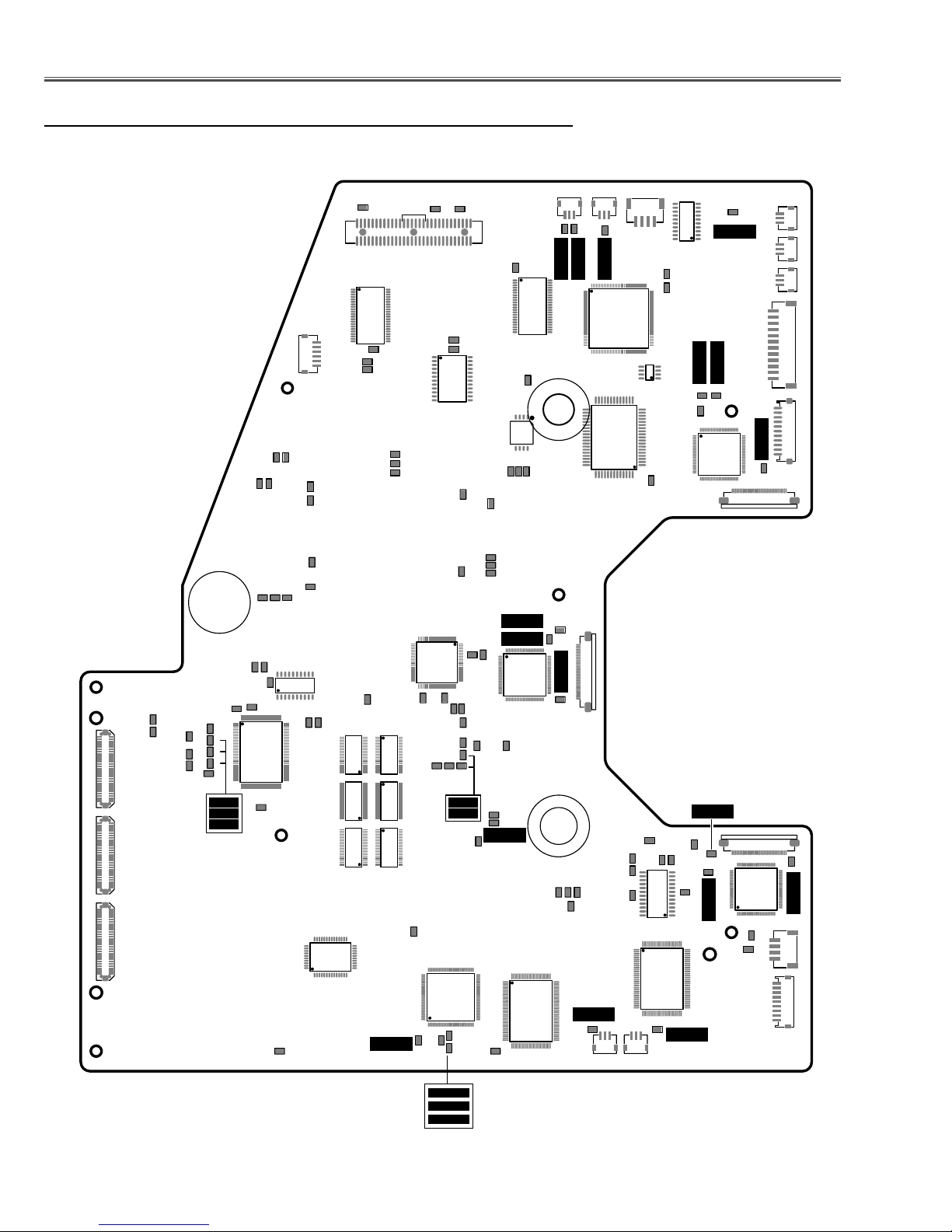
Electrical Adjustments
● MAIN BOARD
Test Points and Locations
TP304
TP303
TP302
TP301
K8H
TP306
TE301
TP351
TP9885
TP9884
TP1301E
IC341
K8W
TPT2
TPT0
TPT3
TP1312
TP1311
TP9851
TP9852
IC9851
TPSW
IC807
TE401
TP805
TPDVS
TP18V
TPDCLK
TPDHS
IC804
K8C
TPFN5
TPFN5
TPFN1
TPFN1
K8N
TPFN6
TPFN6
IC801
IC1801
K8V
IC808
TPSH_R_S
TE3566
TE801
TP801
IC7801
TPV1R
TPV1R
TPFN4
TPV2R
TPV2R
IC2501
TPFN4
TP35R
TP35R
K35R
K8M
K8R
K8U
K8E
K8D
K10Q
K10P K10R
TP814
TP815
TP20R
TP20G
TP20B
TE20
TP21G
TE201
TP21R
TP21B
TP21R
TP21G
TP21B
TPCKB
TPGBLK
TPHS
TPGLK
IC231
TP23D
TPCOAST
TPVS
TPBVCLP1
TE13
TPAD
IC212
TP8002
TP308
TP307
TE202
IC3101
IC3212
IC3213
IC3211
TPGPEN
IC4261
IC4271
IC4251
TPVRB
TPVRB
TP9502
TP2361
TE9401
IC9501
TP9501
TPVD
IC2311
TP13RCR
TP9503
TPGHS
TPHO
TPGHS
TPGVS
TP13GY
TP13BCB
TP9504
TP9506
TRGFBK
TPGVS
TP4021D
TP9507
TPSDATA3
TPIRMSTB
TPSCLK3
TPSH_G_S
TPNRSB
TPNRS
TE2301
TPV1G
TPV2G
IC1501
TPNRSA
TPZNRS
TPNRS
IC6301
TPV1G
TPV2G
TP35G
TP35G
TP4201B
TP1305
TE4202
TPFN7
K35G
TP4201C
TPFN7
TP4201A
TP1306
K8O
TE4231
TP4201
TE8601
TP4201E
TE3536
IC4231
IC6303
TPFN3
TPFN3
K8P
1AA4B10C39300
TPV2B
TPV1B
TPEXTFB
TPV2B
TPV1B
TE3506
K35B
IC501
TPSH_B_S
TP35B
TP35B
K8S
K8J
A_side
TP13GY
TP13RCR
TP13BCB
-25-
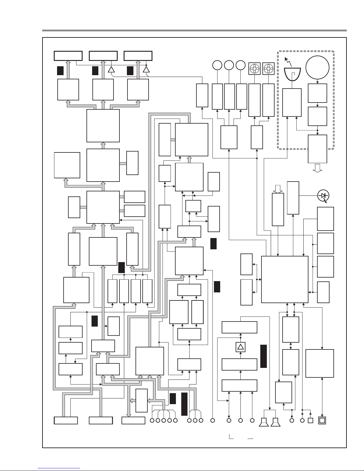
■ Chassis Block Diagrams
● Chassis over view
B-LCD PANEL G-LCD PANEL R-LCD PANEL
NRS
B
IC501
IC9501
B-PANEL
CAPTURE
G
DRIVER
IC304
IC3211,12,13
EEPROM
BUFFER
IC301
IC1501
DRIVER
G-PANEL
IC401
DIGITAL
GAMMA
IC9401
COLOR
AI PICTURE,
MANAGEMENT
SCAN
SYSTEM
CONTROL
CONVERTER,
A/D
IC231
R
IC2501
DRIVER
R-PANEL
IC6301
SDRAM
IC351
FLASH
IC341
SRAM
H/V
BUFFER
IC4251,61,71
H/V
H/V
RECEIVER
RGB
RGB
IC201
RGB-SW
IC1201
RGB
RGB-SW
DIGITAL
RGB
DVI-D
INPUT-1
DIGITAL INPUT
IC3214
BUFFER
IC211
CLAMP
RGB
ANALOG INPUT
IC3251
IC3224
BUFFER
H/V
RGB
RGB
ANALOG
RGB
D-SUB_15
INPUT-1
IC4281
BUFFER
Y,Cb,Cr
IC1202
MON. SW
H/V
IC5304
SYNC SEP.
IC5302
SYNC SW
H/V
IC5301
MON. SW
H/V
ANALOG
RGB
D-SUB_25
NETWORK
OPTION
DVI
IC8001
H/V
NRS
IC6301,02,03,04
IC4231
H/V
IC4541
H/V
BUFFER
IC4101
SELECTOR
RGB
B
G
INPUT-2
SGRAM
VCO
BUFFER
H/V
RGB
HSYNC
R
H
IC4201
IC2311
IC4503
Cb,Cr
Y
IC4531
YUV SW
IC3101
Y/C
IC1141
NT/PAL-SW
Y/C
IC1101
3D-Y/C
IC1141
NT/PAL-SW
CVBS
IC4104
CSYNC SW
Video
Component
V
IC5501
I/P
CONVERTER
A/D
SW
Y
Y,Cb,Cr
VIDEO
DECODER
3L-Y/C
IC2101
Y
VIDEO
Y,Cb,Cr
Y
PB
PR
INPUT-3
DAC
Y/C
IC2341
IC4501
Y/C
Y/C
S-VIDEOCOMPONENT
YUV
MOTORS
MMM
ZOOM
IC1601
IC1602
LENS SHIFT
I/O
IC1641
EXPANDER
CLAMP
SHARPNESS
Y/C
IC1631,IC1632
AUDIO-AMP.
IC1651
PRE-AMP.
IC1652
AUDIO-CONTROL
IC5001
AUDIO-SW
L/R
L/R
PC1
AUDIO
FANS
IC1611
FOCUS
IC7821,41,61,81
IC7801
IC804
S-RAM
IC803
FLASH ROM
L/R
PC2
VIDEO
FANS
IC6602,03
FAN CONTROL
FAN CONTROL
DAC
Audio-L/R
L/R
SPEAKER
LAMP
LAMP
BALLAST
FAIL
POWER
IC1801
I/O EXPANDER
PF_BUFFER
IC5801,31,61,81
CPU
IC801
IC3803
MOUSE
DECODER
F
/
I
IC3802
MOUSE
IC3801
DRIVER
RS-232C
R_R/C
PORT
CONTROL
AC
100~240V
LINE
FILTER
FILTER
ACTIVE
POWER
SUPPLY
SWITCHING
POWER
IC807
PRESSURE
TEMP.
IC1691
TEMP.
IC1871,72
IC808
EEPROM
USB
IC9801
CONTROLLER
USB
F_R/C
LED
SENSOR
SENSOR
SENSOR
-26-
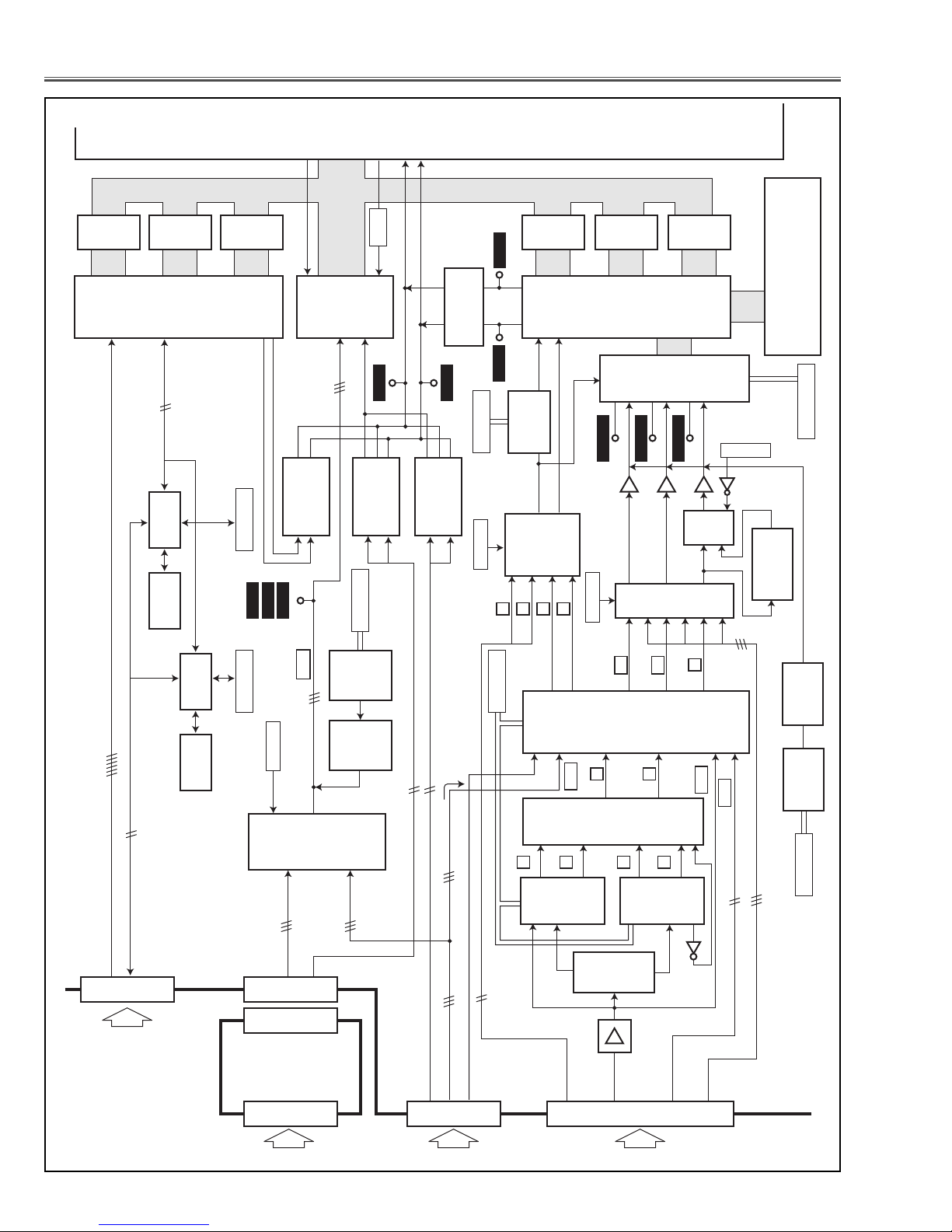
Chassis Block Diagrams
● Video signal processing stage
131
GR
IC3211
BUFFER
D_R
DDC_DATA
GG
IC3212
BUFFER
D_G
IC8001
DVI-RECEIVER
<SII169>
HDCP_CLK/DATA
IC8071
BUS SW
IC8081
PC_DDC
EEPROM
GB
IC3213
BUFFER
D_B
47
D_V
TP21R
48
D_H
2184
TP21B
TP21G
AD_HS
45
IC231
<AD9888>
16
IC3214
BUFFER
<74LCX541>
GR
GG
A/D
5,13,20
100
101
GB
IIC_AD
31,32
44
TPGHS
CG/NET_VS
181516
IC3251
BUFFER
<74LCX541>
2
SCL1/SDA1
GHS_PW
GVS_PW
4
2
1513
IC4281
BUFFER
TPGVS
181516
IC3224
BUFFER
<74LCX541>
4
IC301
SCAN
CONVERTER
IC4251
BUFFER
TPHD
5
24123
7
<74LCX541>
189
TPVD
FUNC_IPV_HSYNC
VCO
IC4231
SCL3/SDA3
TA1370 : L
TB1274 : H
5
H
IC4541
9
V
1274EN2
GR
IC4201
IP CONVERTER
<TC240C4FTB>
189
118
<ICS1523>
V_VSYNC
H/V
BUFFER
CXA2151 : L
2
12
V
H
1274EN1
GG
IC4261
BUFFER
<MB40C348>
11
1
TP13RCR
TP13BCB
IC4551
TB1274 : H
14
12
13
IC4271
BUFFER
IC2311
A/D
13
15
5
TP13GY
IC4552
15
IC4531
YUV SW
2
1
GB
3
RGB : L
OTHERS : H
IC4553
1
5
IC4503
SW
786
4
5
3
NOT_RGB
SGRAM
<MS82V16520>
IC6301, IC6302,IC6303,IC6304
SCLK3/SDATA3
6
IC4501
<NJM1496>
SHARPNESS
IC8061
DDC_CLK
IC8091
HD_DDC
DIGITAL TMDS DATA
DDC_CLK/DATA
K10A
From AV BOARD "K30P"
BUS SW
EEPROM
SCL6/SDA6 SCL3/SDA3
22
11,12
RGB
PC Analog : L
PJ Net : H
CG OUT
20,18,16
IC201
RGB-SW
<AD8183>
8,10,12
NET_RGB
7,8
3,4
15,16
K40A
K70A
K70C
IC212
DAC
<M62393>
IC211
CLAMP
<LT1250>
1,3,5
I/F BOARD
9
4
SCL1/SDA1
VIDEO DECODER
For RGB(SCART) source
NET_H/VSYNC
CG_H/VSYNC
CG_RGB
SCART(CVBS for RGB Scart Sync Signal)
41
25,26,27
RGB
NT/PAL-SW
1
84
IC1101
88
13
C
83
3
Y
NT 3D-Y/C SEP.
<uPD64083>
76
1370_H/V
K10B K10C
CR
23
IC3101
<TB1274>
5
Y
15
IC1141
<4053>
2
Y
PAL 3L-Y/C SEP.
<TC90A69>
IC1141
NT/PAL-SW
<4053>
4
1
IC141
3
CVBS
CB
22
7
C
14
C
25
IC2101
7
5
SVIDEO_Y/C
12
27
Q1143
Y
21
CLAMP
IC2341
<LT1250>
1
43,44
C_V
C, Y
PAL : L
NTSC : H
9
17
NT-PAL
DAC
IC9405
<M62392>
SCL1/SDA1
2151_Y/CB/CR
NETWORK OPTION
From AV BOARD "K30R"From AV BOARD "K30Q"
-27-
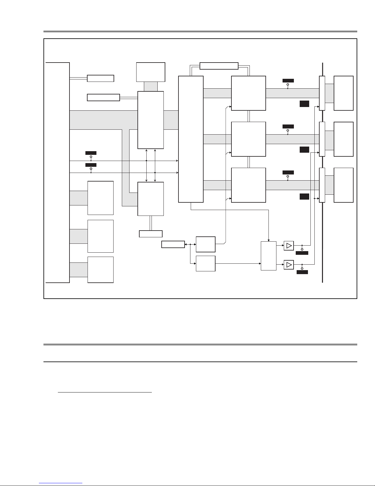
● LCD panel driving stage
Chassis Block Diagrams
4.
No picture from all of sources
Check HSYNC signal at test point TPGHS and VSYNC signal at TPGVS.
Check RGB S&H signals at test points TP35R, TP35G and TP35B.
Check NRS signals at test point TPNRS and TPZNRS.
Check power supply circuit 15VL and 15VP and peripheral circuit.
Check ICs IC501, IC1501, IC2501, IC9401, IC401 and peripheral circuits.
● No Picture
❈ Differences as below
■ Troubleshooting
CONVERTER
SCAN
IC301
DR
DG
DB
323
244
A0-A16
D0-D15
A1-A19
D0-D15
PW_SDA
PW_SCL
PW_RXD/TXD
RD/WRL/WRH/CS
TP308
DHS
TP307
DVS
IC341
S-RAM
IC351
FLASH
ROM
IC304
CONTROL
MEMORY
<24LC168>
IC9402
SDRAM
<EM638325>
SDIF
COLOR MANAGEMENT
<JS1110074>
AI PICTURE,
IC9401
23
609662
IC9501
CAPTURE
<uPD65943>
RD/WRL/CS
BAOUT
GAOUT
BAOUT
66
67
SCL5/SDA5
SCLK3/SDATA3/STB3
DIGITAL GAMMA
CORRECTION
<L3E07070>
IC401
IC5531
DAC
<M62399>
IC5501
DAC
<M62399>
DBSH
DGSH
DRSH
FPRR,FPRG
4,5,12-15
12,13
B-LCD DRIVER
<L3E06110>
G-LCD DRIVER
<L3E06110>
R-LCD DRIVER
<L3E06110>
R/G/B_V1/V2
NRSA/NRSB
IC501
IC1501
IC2501
IC1560
NRS_SW
<4053>
TP35B
TP35G
TP35R
IC1621
NRS
<LM7171>
+
+
IC1631
NRS
<LT1206>
B
G
R
TPZNRS
TPNRS
K35RK35GK35B
B-LCD
PANEL
G-LCD
PANEL
R-LCD
PANEL
 Loading...