

Sanyo PLC-XP46,PLC-XP46L Owner's Manual
FILE NO.
Notice
CORRECTION
●
PRODUCTION CHANGE
SERVICE FLASH ADD INFORMATION
REVISION-4
Please add this notice to the Service Manual listed below.
Category : Multi-media Projector Issued Date : June / 2004
PLC-XP46 MA8-XP4602
Model : PLC-XP46L
Effective from :
Chassis No. MA8-XP46L01
Canada, U.S./Europe,
Destination : Asia, Africa, U.K. REF. NO. : SM5110329
NOTE: Match the Chassis No. on the unit’s back cover with the Chassis No. in the Service
Manual.
If the Chassis. No. does not match the unit’s, additional service literature is required.
Only the difference service information is given in this manual. For detailed service information, refer to the original service manual SM5110329, issued in April 2002, for
Models PLC-XP46/46L.
PRODUCT CODE
PLC-XP46
PLC-XP46L
1 122 177 30 (MK3AA) 1 122 177 40 (MK3AM)
1 122 180 30 (PK3AA) 1 122 180 40 (PK3AM)
1 122 180 32 (PK3CA) 1 122 180 42 (PK3CM)
REFERENCE NO. SM5110329-04
FILE WITH ORIGINAL SERVICE MANUAL (SM5110329)
Differences:
Outline
PLC-XP46 Power and Sub Power Board were changed.
PLC-XP46L LCD panels and Main Board were changed.
Power and Sub Power Board were changed.
-2-
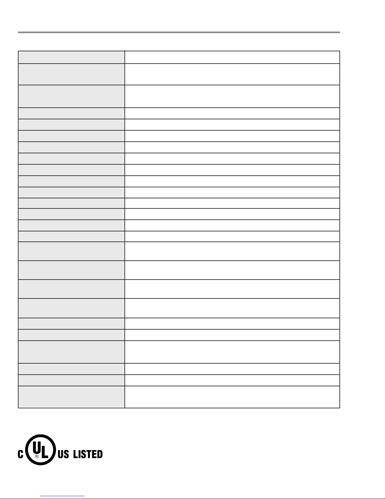
■ Specifications
● The specifications are subject to change without notice.
This symbol on the nameplate means the product is Listed by Underwriters
Laboratories Inc. It is designed and manufactured to meet rigid U.L. safety standards against risk of fire, casualty and electrical hazards.
Projector Type Multi-media Projector
Dimensions (W x H x D) 12.6” x 6.6” x 18.5” (319mm x 168mm x 470mm) (PLC-XP46)
12.6” x 6.6” x 16.8” (319mm x 168mm x 429.5mm) (PLC-X46L)
Net Weight 18.5 lbs (8.4 kg) (PLC-XP46)
15.7 lbs (7.1 kg) (PLC-X46L)
LCD Panel System 1.3” TFT Active Matrix type, 3 panels
Panel Resolution 1024 x 768 dots
Number of Pixels 2,359,296 (1024 x 768 x 3 panels)
Color System 6 color system (PAL, SECAM, NTSC, NTSC4.43, PAL-M and PAL-N)
High Definition TV SIgnals 480i, 480p, 575i, 575p, 720p. 1035i and 1080i
Scanning Frequency H-sync. 15 ~ 100kHz, V-sync. 50 ~ 100Hz
Projection Image Size (diagonal) Adjustable from 31” to 400”
Horizontal Resolution 800 TV lines (HDTV)
Projection Lens F 1.7 ~2.0 lens with f=48.2mm ~ 62.6mm with motor zoom and focus (PLC-XP46)
Throw Distance 4.6’ ~ 48.3’ (1.4m ~ 14.7m)(PLC-XP46)
Motorized Lens Shift Up and Down
Projection Lamp 275watts
Input 1 Jacks DVI Terminal (Digital), HDB 15-pin Terminal (Analog) and Stereo Mini Type
Jack (Audio)
Input 2 Jacks BNC Type x 5 (G or VIDEO/Y, B or Cb/Pb, R or Cr/Pr, H and V), Stereo
Mini Type Jack (Audio)
Input 3 Jacks RCA Type x 3 (VIDEO/Y, Cb/Pb, Cr/Pr), RCA Type x 2 (Audio R and L) and
DIN 4-pin (S-Video)
Other Jacks DIN 8-pin (Control port), USB port (Series B receptacle), Wired Remote
Jack and Network Board Connector Jack
Built-in Speakers 2 speakers Stereo (R and L), 2 watts RMS (T.H.D. 10%)
Feet Adjustment 0˚ to 10.5˚
Voltage and AC 100 ~ 120V (4.8A Max. Ampere), 50/60Hz (The U.S.A and Canada)
Power Consumption AC 200 ~ 240V (2.4A Max. Ampere), 50/60Hz (Continental Europe)
Operating Temperature 41 ˚F ~ 95 ˚F (5˚C ~ 35˚C)
Storage Temperature 14 ˚F ~ 140 ˚F (-10˚C ~ 60˚C)
Remote Control Transmitters Wireless/Wired Remote Control, batteries AA, UM3 or R06 Type x 2
-3-
Condenser lens adjustment ❍●
Relay lens adjustment ❍●
Contrast Adjustment
R-Contrast adjustment ●
G-Contrast adjustment ●
B-Contrast adjustment ●
Output voltage adjustment
+16 V adjustment ●●
Video center adjustment ●
PSIG adjustment ●
PC pedestal adjustment ●
Black level adjustment ●
PC gain adjustment ●
PC gamma shift adjustment ●
HDTV pedestal adjustment ●
HDTV A/D input adjustment ●
HDTV Gain adjustment ●
Video pedestal adjustment ●
Video A/D input adjustment ●
A/D offset adjustment ●
Video gain adjustment ●
Video gamma shift adjustment ●
Common center adjustment ● ●
White balance adjustment ❍ ❍
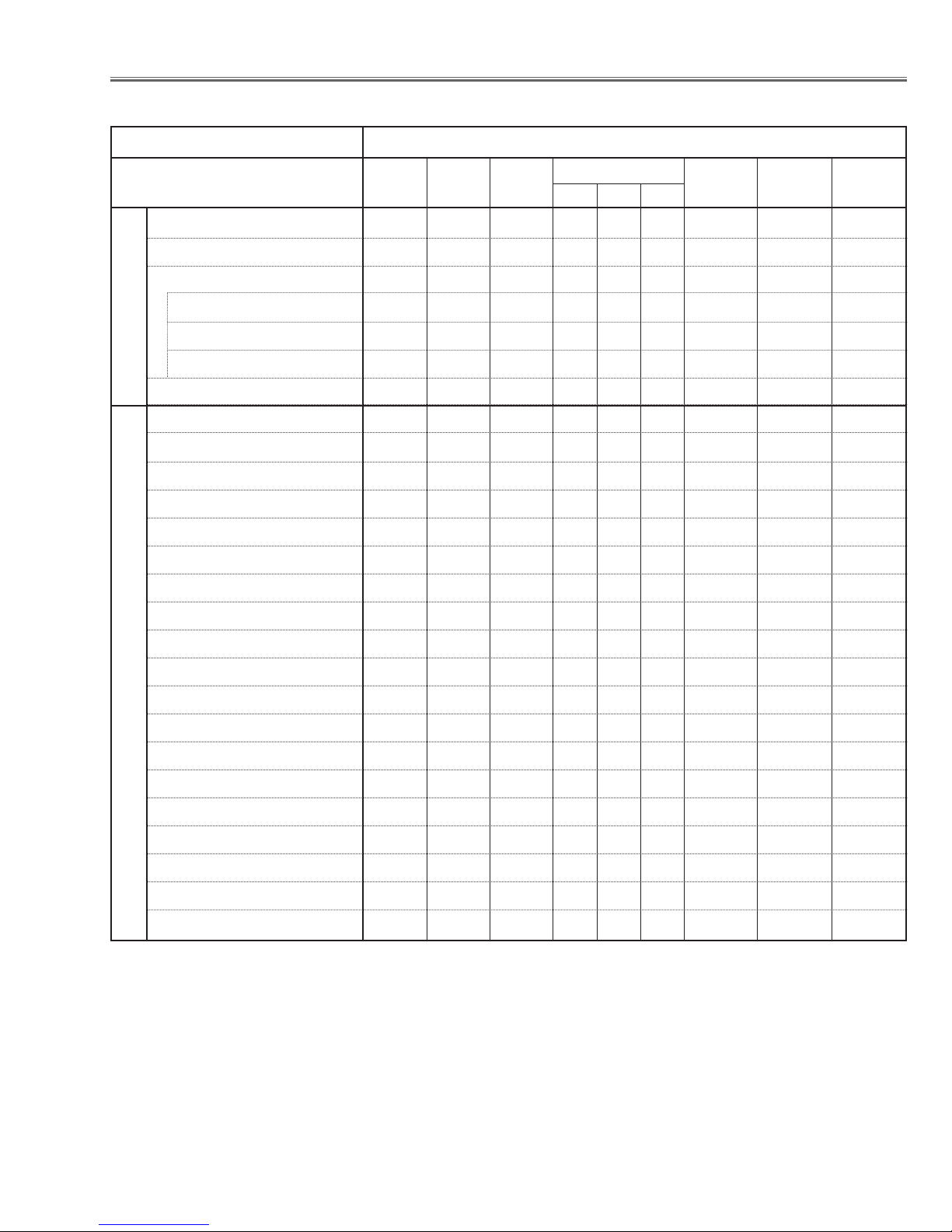
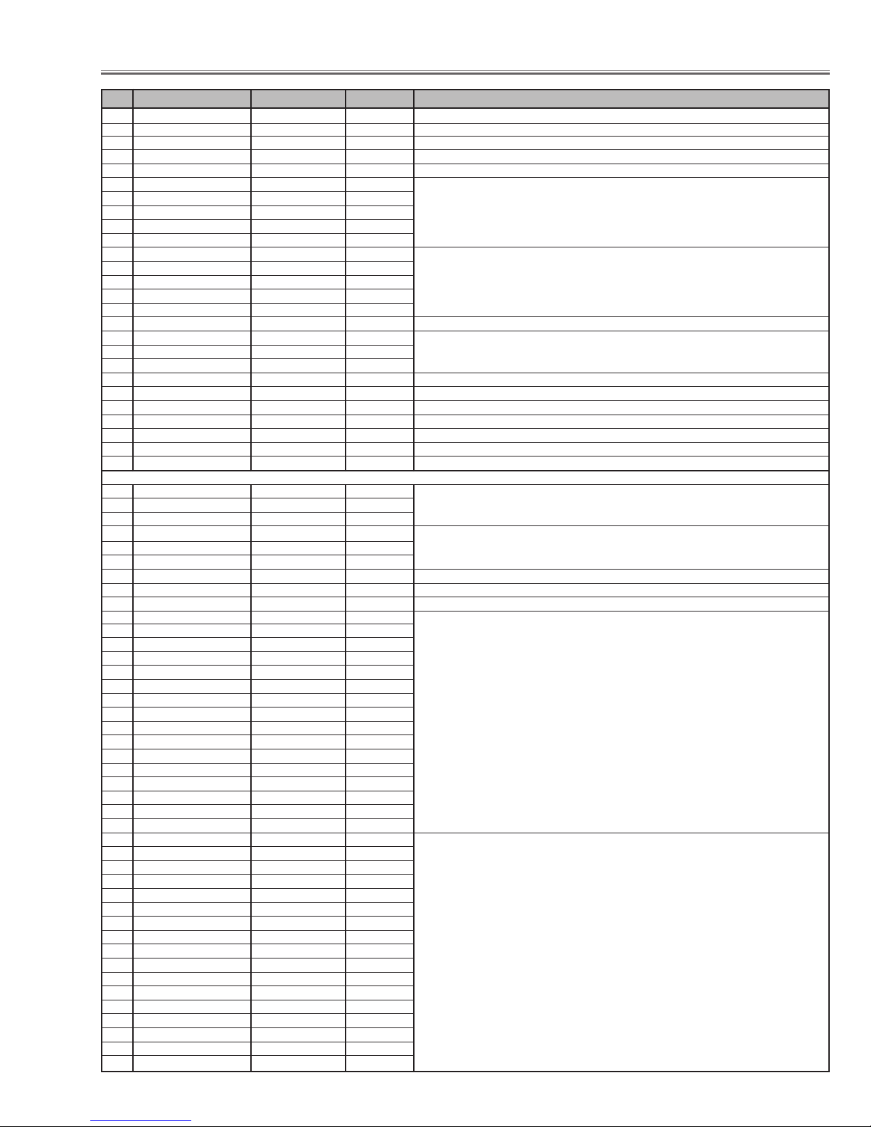
Disassembly / Replaced Parts
LCD/
Prism
Ass’y
Condenser
Lens
Polarized glass
RGB
Optical Adjustments
Electrical Adjustments
● : Adjustment necessary ❍ : Check necessary
Sub Power
Board
Main Board
Relay
Lens
■ Adjustments after Parts Replacement
Powe r
Board
-4-
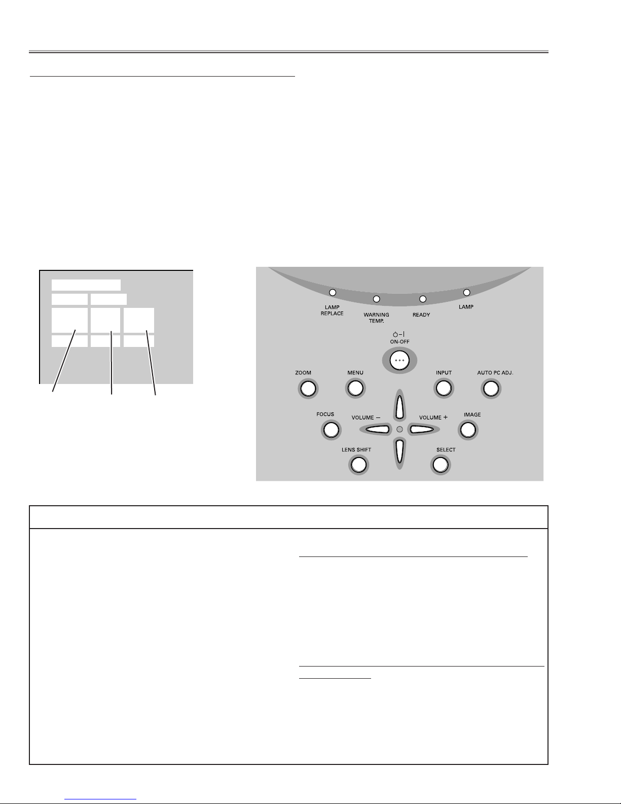
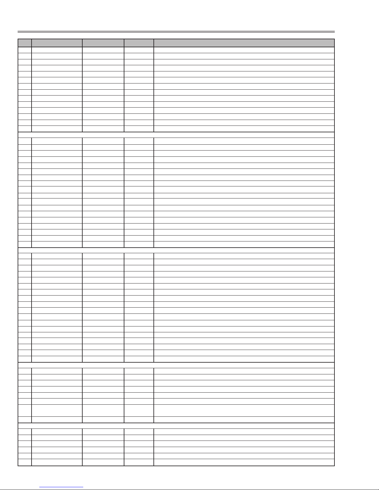
■ Electrical Adjustments
To enter the service mode
To enter the “Service Mode”, press and hold the MENU and IMAGE button on the projector at the same time for
more than 3 seconds. The service menu appears on the screen as follows.
To adjust service data
Select the adjustment group no. by pressing the MENU (+) or IMAGE (-) button, and select the adjustment item
no. by pressing the pointer UP or DOWN button, and change the data value by pressing the VOLUME – or VOL-
UME + button. Refer to the “Service Adjustment Data Table” for further description of adjustment group no., item
no. and data value.
To exit the service mode
To exit the service mode, press the POWER ON-OFF button on the projector or remote control unit.
● Service Adjustment Menu Operation
IC808 on the main board stores the data for the service adjustments, and should not be replaced except for
the case of defective device.
If replaced, it should be performed the re-adjustments
following to the “Electrical Adjustments”.
The data of lamp replacement monitor timer is stored
in the IC808.
Please note that the lamp replace counter is reset
when the memory IC (IC808) is replaced.
(Lamp replace counter can not be set to the previous
value.)
● Caution to memory IC replacement
When IC808 is replaced with new one, the CPU writes
down the default data of the service adjustments to the
replaced IC, refer to the service adjustment table. As
these data are not the same data as factory shipped
data, it should be required to perform the re-adjust-
ments following to the “Electrical Adjustments”.
Please note that the lamp replace counter is reset.
● Caution of Main Board replacement (in the case
IC808 is not defective)
When the main board is replaced, IC808 should be
replaced with the one on previous main board. After
replacement, it should be required to perform the readjustments following to the “Electrical Adjustments”.
In this case, the lamp replace counter can be kept the
v
alue as before.
● Memory IC Replacement
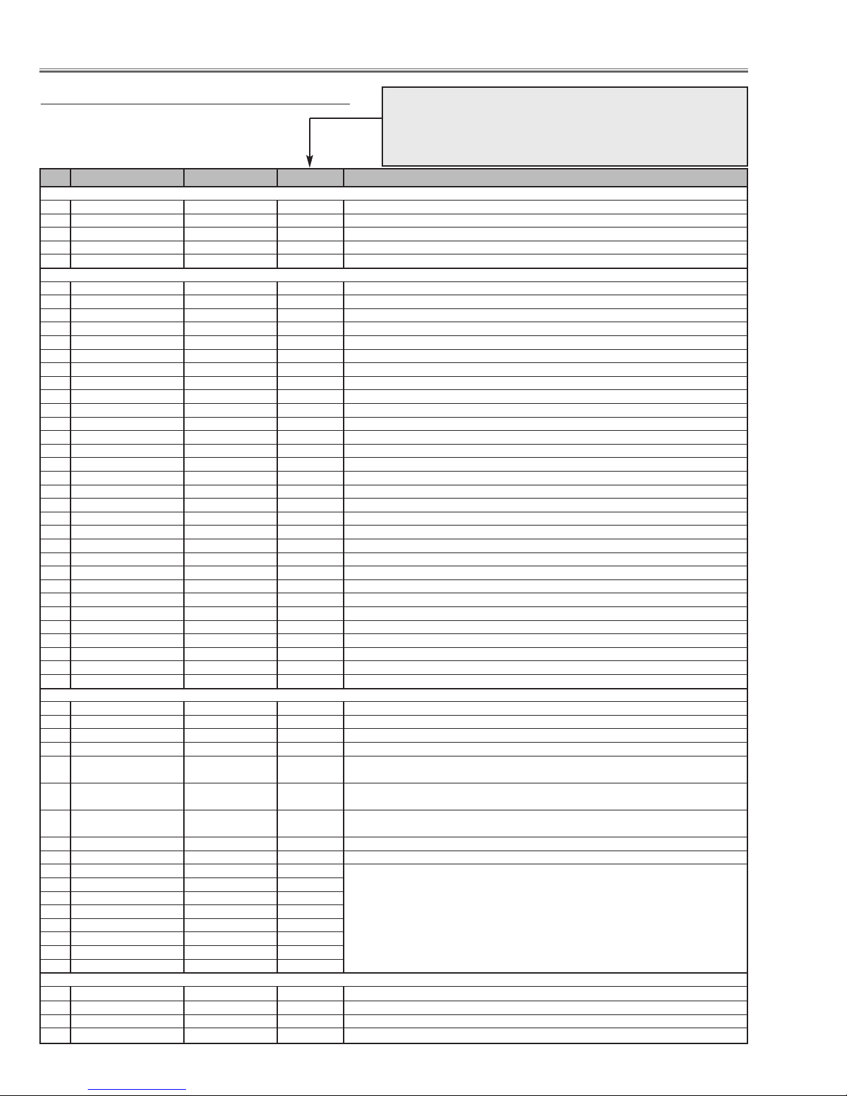
Group No.
Data value
Item No.
Service Mode
Input 1
Group No. Data
0032
Ver. 1.00 .00
-5-
[Adjustment Condition]
● Input signal
Video signal .......................... 1.0Vp-p/75Ω terminated, 16 steps gray
scale (Composite video signal)
Computer signal .................... 0.7Vp-p/75Ω terminated, 16 steps gray
scale pattern (XGA)
Component Video signal ...... 0.7Vp-p/75Ω terminated, 16 steps gray
scale (Component video signal with
480p or 1080i format)
● Picture control mode .............. “STANDARD” mode unless otherwise
noted.
Note:
* Please refer to “Service Adjustment Menu Operation” for entering to the service mode and adjusting the service
data.
After replacing the Power Board readjust the Output
voltage adjustment as follows.
1. Connect a digital voltmeter to pin 1 (+) of K6A and
pin 3 (-) of K6A.
2. Adjust the voltage by using VR601 on the power
board as following.
AC Input Reading
230V 370 ±2Vdc
or 120V 340 ±2Vdc
Caution:
Be sure to connect the lamp when taking this adjustment.
● Circuit Adjustments
CAUTION: The each circuit has been made by the fine adjustment at factory. Do not attempt to adjust the follow-
ing adjustments except requiring the readjustments in servicing otherwise it may cause loss of performance and product safety.
Electrical Adjustments
Output Voltage adjustment
1. Receive the 16-step gray scale video signal with
Input 3 [VIDEO] mode.
2. Connect a digital voltmeter to pin 3 (+) of CN6A and
chassis ground (-).
3. Adjust the voltage to be 15.8 ±0.1Vdc by using
VR681 on the power board.
+16V adjustment
1. Receive the 16-step gray scale computer signal with
Input 1 [COMPUTER] mode.
2. Enter the service mode.
3. Connect a digital voltmeter to test point “TP531”(+)
and chassis ground (-).
4. Select group no. “5”, item no. “1” and change data
value to adjust the voltage to be 7.50 ±0.1Vdc.
5. Connect a digital voltmeter to test point “TP501”(+)
and chassis ground (-).
6. Select item no. “0” and change data value to adjust
the voltage to be 7.50 ±0.1Vdc.
7. Connect a digital voltmeter to test point “TP561”(+)
and chassis ground (-).
8. Select item no. “2” and change data value to adjust
the voltage to be 7.50 ±0.1Vdc.
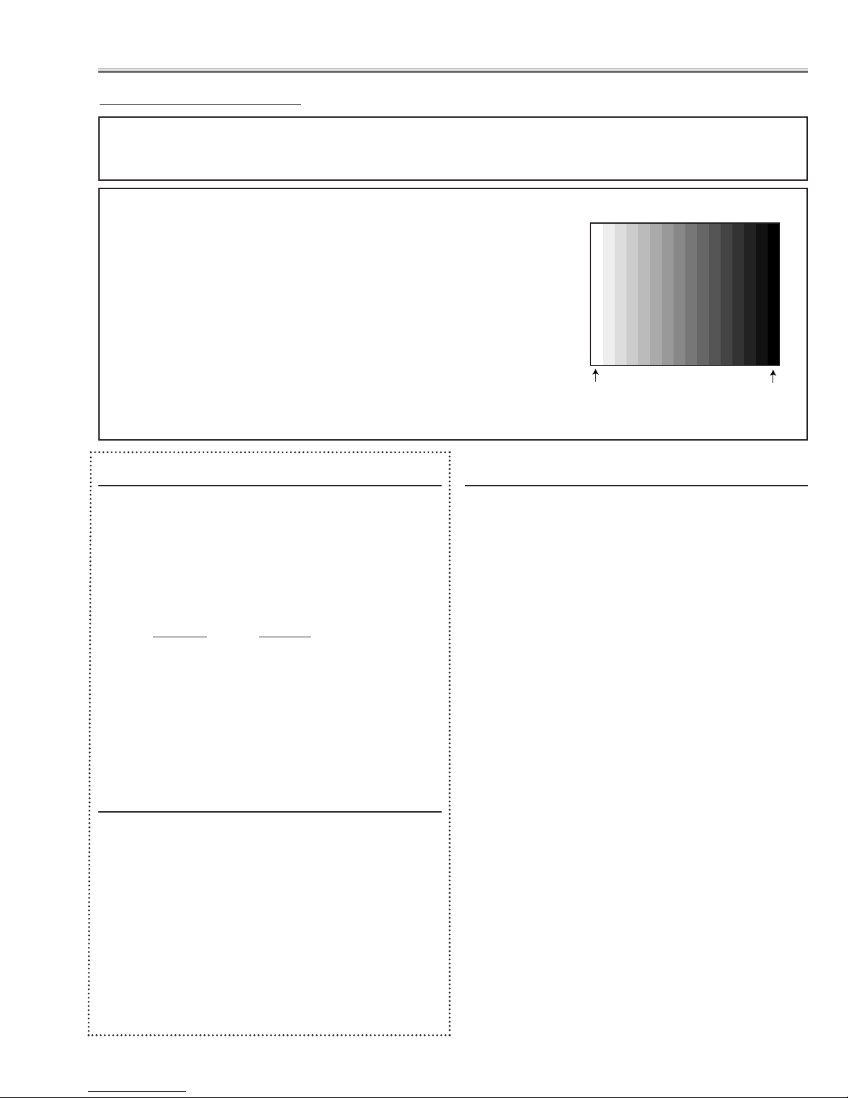
Video Center adjustment
16 steps gray scale pattern
Note:
The above adjustments are carried out at the spare
parts shipment, therefore it is not required when replacing the power board.
White 100%
Black 100%
-6-
Electrical Adjustments
1. Receive the 16-step gray scale computer signal with
Input 1 [COMPUTER] mode.
2. Enter the service mode.
3. Connect an oscilloscope to test point “TP531” (+) and
chassis ground (-).
4. Select group no. “5”, item no. “16” and change data
value to adjust the pedestal level and black level to be
the same level.
5. Connect an oscilloscope to test point “TP501” (+) and
chassis ground (-).
6. Select item no. “15” and change data value to adjust
the pedestal level and black level to be the same
level.
7. Connect an oscilloscope to test point “TP561” (+) and
chassis ground (-).
8. Select item no. “17” and change data value to adjust
the pedestal level and black level to be the same
level.
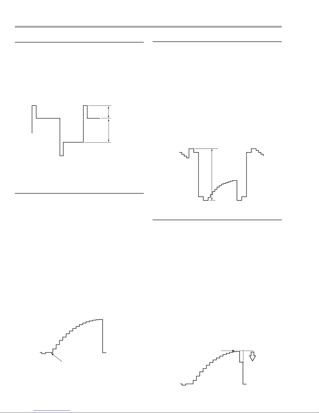
PC Pedestal adjustment
1. Receive the 16-step gray scale computer signal with
Input 1 [COMPUTER] mode.
2. Enter the service mode.
3. Connect an oscilloscope to test point “TP531” (+)
and chassis ground (-).
4. Select group no. “5”, item no. “4” and change data
value to adjust amplitude “a” to be 10.0 ±0.1V.
5. Connect an oscilloscope to test point “TP501”(+)
and chassis ground (-).
6. Select item no. “3” and change data value to adjust
amplitude “a” to be 10.0 ±0.1V.
7. Connect an oscilloscope to test point “TP561”(+)
and chassis ground (-).
8. Select item no. “5” and change data value to adjust
amplitude “a” to be 10.0 ±0.1V.
Black Level adjustment
1. Receive the 16-step gray scale computer signal with
Input 1 [COMPUTER] mode.
2. Enter the service mode.
3. Connect an oscilloscope to test point “TP531”(+)
and chassis ground (-).
4. Select group no. “4”, item no. “4” and set data value
to “600”, and then decrease data to adjust waveform
“a” to be minimum amplitude.
5. Connect an oscilloscope to test point “TP501”(+)
and chassis ground (-).
6. Select item no. “5” and set data value to “600”, and
then decrease data to adjust waveform “a” to be minimum amplitude.
7. Connect an oscilloscope to test point “TP561”(+)
and chassis ground (-).
8. Select item no. “3” and set data value to “580”, and
then decrease data to adjust waveform “a” to be minimum amplitude.
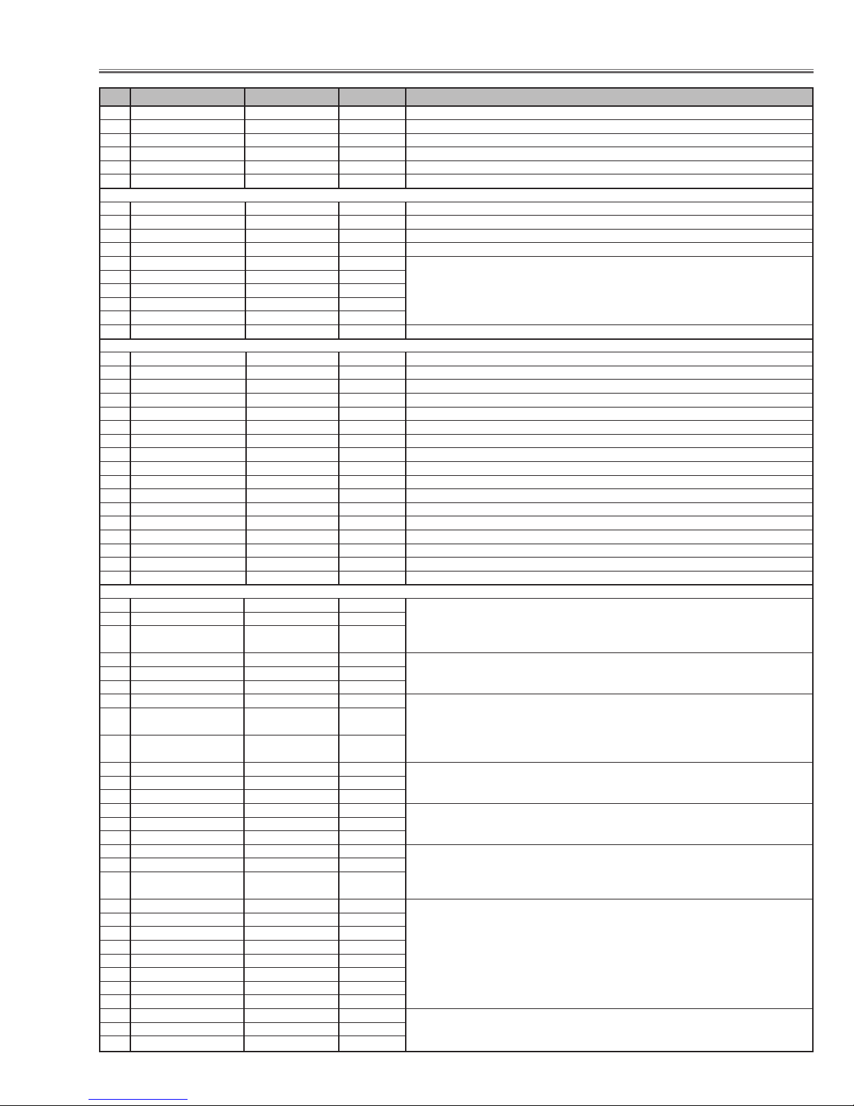
PC Gain adjustment
1. Receive the a6-step gray scale computer signal with
Input 1 [COMPUTER] mode.
2. Enter the service mode.
3. Connect an oscilloscope to test point “2551” (+) and
chassis ground (-).
4. Select group no. “5”, item no. “6” and change data
value to adjust amplitude “a” to be 3.8 ±0.1V.
5. Select item no. “8” and change data value to adjust
amplitude “b” to be 3.1 ±0.1V.
PSIG adjustment
(b)
(a)
black level
(a)
black level
Pedestal Lebel = Black Lebel
White Level
(a)

-7-
Electrical Adjustments
1. Receive the 16-step gray scale computer signal with
Input 1 [COMPUTER] mode.
2. Enter the service mode.
3. Select group no. “4”, item no. “6” and change data
value to reproduce the proper gray scale picture on
the screen.
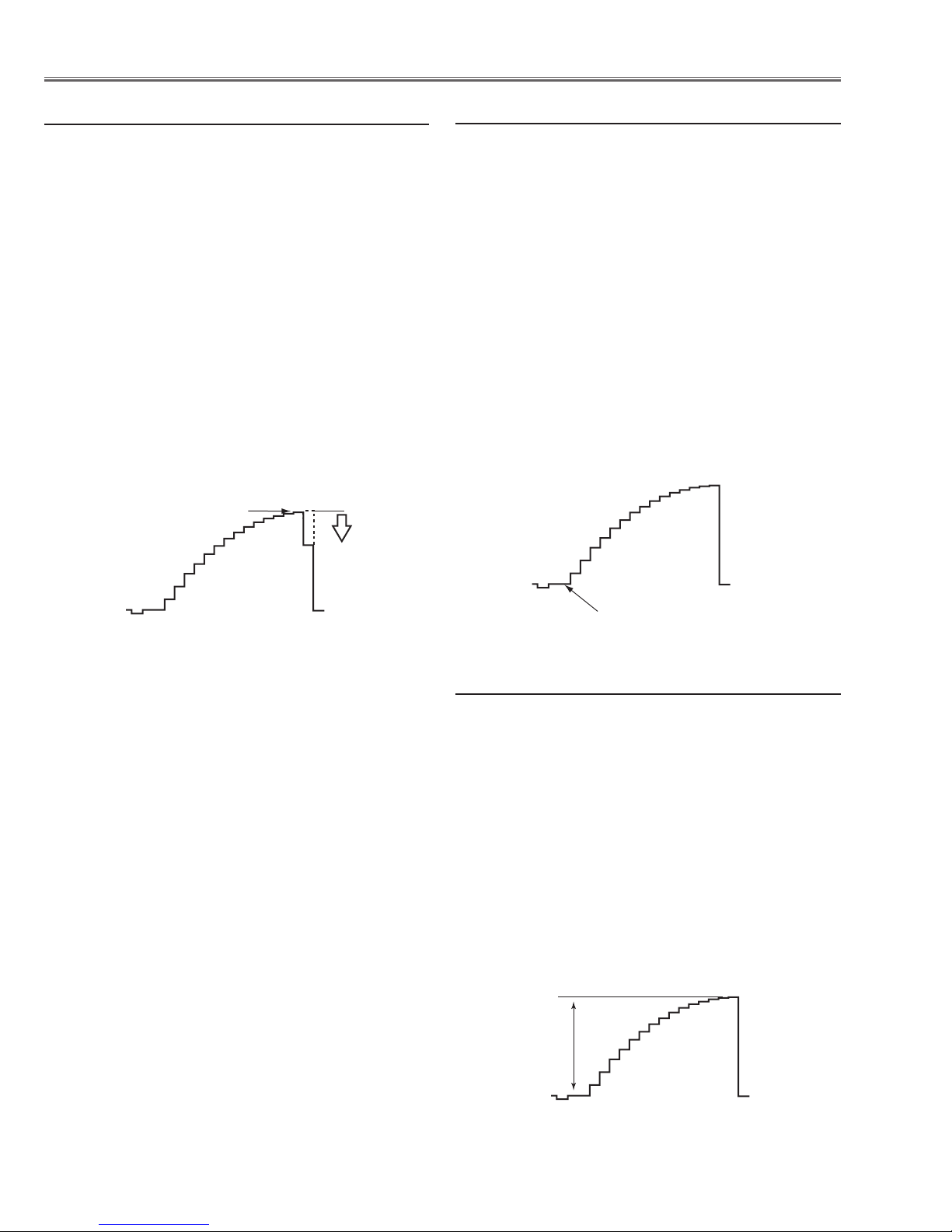
PC Gamma Shift adjustment
[480p-PEDESTAL ADJUSTMENT]
1. Receive the 16-step gray scale component signal
[480p] with Input 3 [COMPONENT] mode.
2. Enter the service mode.
3. Connect an oscilloscope to test point “TP21G”(+)
and chassis ground (-).
4. Select group no. “3”, item no. “1” and change data
value to adjust the pedestal level and black level to be
the same level.
5. Connect an oscilloscope to test point “TP21B”(+)
and chassis ground (-).
6. Select group no. “5”, item no. “14” and change data
value to adjust the pedestal level and black level to be
the same level.
7. Connect an oscilloscope to test point “TP21R”(+)
and chassis ground (-).
8. Select item no. “13 and change data value to adjust
the pedestal level and black level to be the same
level.
[1080i-PEDESTAL ADJUSTMENT]
1. Receive the 16-step gray scale component signal
[1080i] with Input 3 [COMPONENT] mode.
2. Enter the service mode.
3. Connect an oscilloscope to test point “TP21G”(+)
and chassis ground (-).
4. Select group no. “3”, item no. “1” and change data
value to adjust the pedestal level and black level to be
the same level.
5. Connect an oscilloscope to test point “TP21B”(+)
and chassis ground (-).
6. Select group no. “5”, item no. “14” and change data
value to adjust the pedestal level and black level to be
the same level.
7. Connect an oscilloscope to test point “TP21R”(+)
and chassis ground (-).
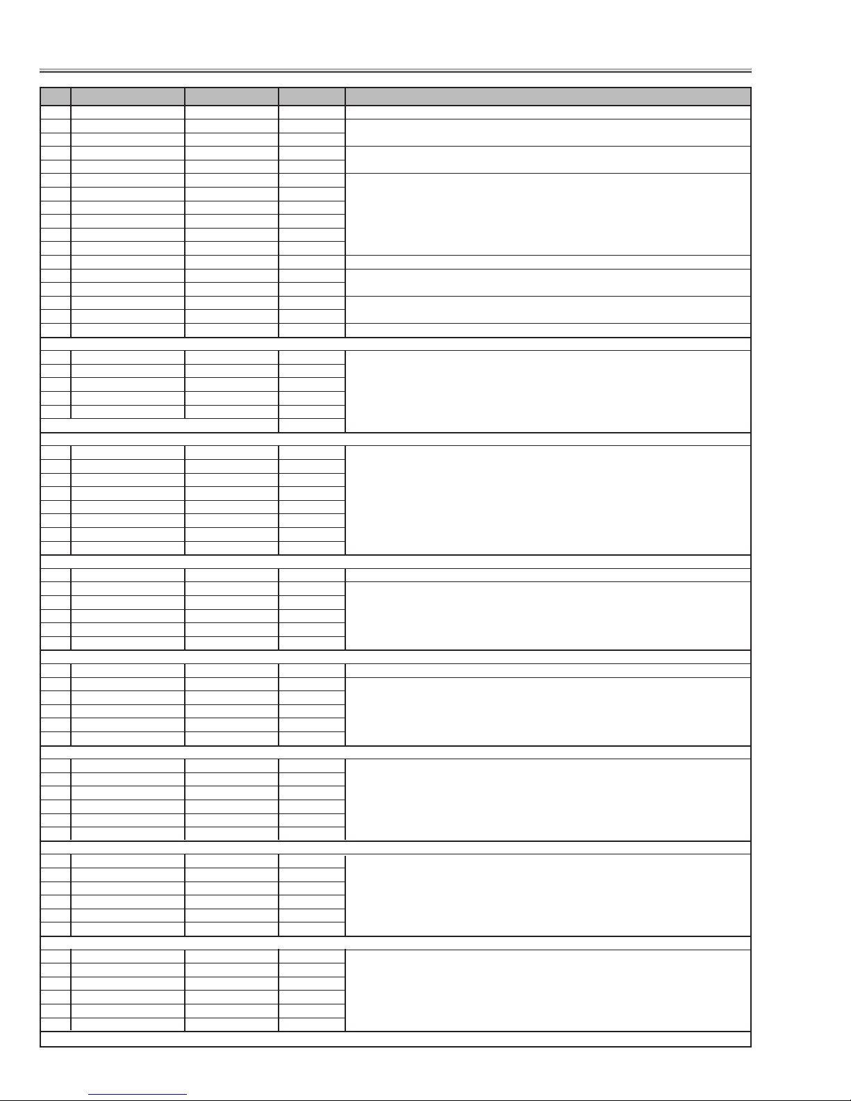
HDTV Pedestal adjustment
8. Select item no. “13 and change data value to adjust
the pedestal level and black level to be the same
level.
[480p-A/D INPUT ADJUSTMENT]
1. Receive the 16-step gray scale component signal
[480p] with Input 3 [COMPONENT] mode.
2. Enter the service mode.
3. Connect an oscilloscope to test point “TP21G”(+)
and chassis ground (-).
4. Select group no. “3”, item no. “0” and change data
value to adjust amplitude “a” to be 0.9 ±0.1V.
5. Connect an oscilloscope to test point “TP21B”(+)
and chassis ground (-).
6. Select item no. “4” and change data value to adjust
amplitude “a” to be 0.9 ±0.1V.
7. Connect an oscilloscope to test point “TP21R”(+)
and chassis ground (-).
8. Select item no. “2 and change data value to adjust
amplitude “a” to be 0.9 ±0.1V.
[1080i-A/D INPUT ADJUSTMENT]
1. Receive the 16-step gray scale component signal
[1080i] with Input 3 [COMPONENT] mode.
2. Enter the service mode.
3. Connect an oscilloscope to test point “TP21G”(+)
and chassis ground (-).
4. Select group no. “
3”, item no. “0” and change data
value to adjust amplitude “a” to be 0.9 ±0.1V.
5. Connect an oscilloscope to test point “TP21B”(+)
and chassis ground (-).
6. Select item no. “4” and change data value to adjust
amplitude “a” to be 0.9 ±0.1V.
7. Connect an oscilloscope to test point “TP21R”(+)
and chassis ground (-).
8. Select item no. “2 and change data value to adjust
amplitude “a” to be 0.9 ±0.1V.
Note: This adjustment should be done after HDTV
Pedestal adjustment.
HDTV A/D Input adjustment
(a)
Pedestal Lebel = Black Lebel
(a)
-8-
1. Receive the 16-step gray scale component signal
[1080i] with Input 3 [COMPONENT] mode.
2. Enter the service mode.
3. Connect an oscilloscope to test point “TP531”(+)
and chassis ground (-).
4. Select group no. “4”, item no. “4” and set data value
to “600”, and then decrease data to adjust waveform
“a” to be minimum amplitude.
5. Connect an oscilloscope to test point “TP501”(+)
and chassis ground (-).
6. Select item no. “5” and set data value to “600”, and
then decrease data to adjust waveform “a” to be minimum amplitude.
7. Connect an oscilloscope to test point “TP561”(+)
and chassis ground (-).
8. Select item no. “
3” and set data value to “600”, and
then decrease data to adjust waveform “a” to be minimum amplitude.
HDTV Gain adjustment
1. Receive the 16-step gray scale video signal with
Input 3 [VIDEO] mode.
2. Enter the service mode.
3. Connect an oscilloscope to test point “TP4151G”(+)
and chassis ground (-).
4. Select group no. “3”, item no. “1” and change data
value to adjust the pedestal level and black level to be
the same level.
5. Connect an oscilloscope to test point “TP4151B”(+)
and chassis ground (-).
6. Select group no. “5”, item no. “14” and change data
value to adjust the pedestal level and black level to be
the same level.
7. Connect an oscilloscope to test point “TP4151R”(+)
and chassis ground (-).
8. Select item no. “13 and change data value to adjust
the pedestal level and black level to be the same
level.
VIDEO Pedestal adjustment
1. Receive the 16-step gray scale video signal with
Input 3 [VIDEO] mode.
2. Enter the service mode.
3. Connect an oscilloscope to test point “TP4151G”(+)
and chassis ground (-).
4. Select group no. “3”, item no. “0” and change data
value to adjust amplitude “a” to be 0.8 ±0.1V.
5. Connect an oscilloscope to test point “TP4151B”(+)
and chassis ground (-).
6. Select item no. “4” and change data value to adjust
amplitude “a” to be 0.8 ±0.1V.
7. Connect an oscilloscope to test point “TP4151R”(+)
and chassis ground (-).
8. Select item no. “2 and change data value to adjust
amplitude “a” to be 0.8 ±0.1V.
Note: This adjustment should be done after VIDEO
Pedestal adjustment.
VIDEO A/D Input adjustment
Electrical Adjustments
White Level
(a)
Pedestal Lebel = Black Lebel
(a)

-9-
1. Receive the 16-step gray scale video signal with
Input 3 [VIDEO] mode.
2. Enter the service mode.
3. Connect an oscilloscope to test point “TP531” (+) and
chassis ground (-).
4. Select group no. “6”, item no. “11” and change data
value to adjust the pedestal level and black level to be
the same level.
5. Connect an oscilloscope to test point “TP501” (+) and
chassis ground (-).
6. Select item no. “12” and change data value to adjust
the pedestal level and black level to be the same
level.
7. Connect an oscilloscope to test point “TP561” (+) and
chassis ground (-).
8. Select item no. “10 and change data value to adjust
the pedestal level and black level to be the same
level.
1. Receive the 16-step gray scale computer signal with
Input 1 [COMPUTER] mode.
2. Enter the service mode.
3. Project only green light component to the screen.
4. Select group no. “5”, item no. “11” and change data
value to obtain the minimum flicker on the screen.
5. Project only blue light component to the screen.
6. Select item no. “12” and change data value to obtain
the minimum flicker on the screen.
7. Project only red light component to the screen.
8. Select item no. “10” and change data value to obtain
the minimum flicker on the screen.
A/D Offset adjustment
Common Center adjustment
[PC WHITE BALANCE ADJUSTMENT]
1. Receive the 16-step gray scale computer signal with
Input 1 [COMPUTER] mode.
2. Enter the service mode.
3. Select group no. “4”, item no. “7” (Red) or “8”(Blue),
and change data values respectively to make a proper white balance.
[AV WHITE BALANCE ADJUSTMENT]
4. Receive the 16-step gray scale video signal with
Input 3 [VIDEO] mode.
5. Enter the service mode.
6. Select group no. “4”, item no. “7” (Red) or “8”(Blue),
and change data values respectively to make a proper white balance.
Confirm that the same white balance is obtained in
video and computer input.
White Balance adjustment
If you find the color shading on the screen, please
adjust the white uniformity by using the proper computer and “Color Shading Correction” software supplied
separately. The software can be ordered as follows;
COLOR SHADING CORRECTION SOFTWARE
Ser
vice Parts No. 645 051 2308
NOTE ON WHITE UNIFORMITY
ADJUSTMENT
1. Receive the 16-step gray scale video signal with Input
3 [VIDEO] mode.
2. Enter the service mode.
3. Connect an oscilloscope to test point “TP531”(+)
and chassis ground (-).
4. Select group no. “4”, item no. “4” and set data value
to “600”, and then decrease data to adjust waveform
“a” to be minimum amplitude.
5. Connect an oscilloscope to test point “TP501”(+)
and chassis ground (-).
6. Select item no. “5” and set data value to “600”, and
then decrease data to adjust waveform “a” to be minimum amplitude.
7. Connect an oscilloscope to test point “TP561”(+)
and chassis ground (-).
8. Select item no. “3” and set data value to “580”, and
then decrease data to adjust waveform “a” to be minimum amplitude.
Video Gain adjustment
1. Receive the 16-step gray scale video signal with
Input 3 [VIDEO] mode.
2. Enter the service mode.
3. Select group no. “4”, item no. “6” and change data
value to reproduce the proper gray scale picture on
the screen.
Video Gamma Shift adjustment
Electrical Adjustments
Pedestal Lebel = Black Lebel
White Level
(a)
-10-
Group: 0 TC90A26
0Y-EQ_GAIN 3 0 ~ 3
1Y-EQ_N_C_LIM 3 0 ~ 3
2V-ENH_GAIN 4 0 ~ 7
3 V_ENH_CORING 2 0 ~ 3
4 NTSC443_SW 1 0 ~ 1 Input signal setting 0:NTSC4.43 1:PAL60 (Only effective for NTSC4.43 signal inputs)
Group: 1 uPD64082
0 NRMD 0 0 ~ 3
1 HDP 4 0 ~ 7
2 CDL 4 0 ~ 7
3DYCOR 4 0 ~ 15
4DYGAIN 15 0 ~ 15
5 DCCOR 2 0 ~ 15
6 DCGAIN 13 0 ~ 15
7 YNRK 0 0 or 1
8 YNRINV 0 0 or 1
9 YNRLIM 0 0 ~ 3
10 CNRK 0 0 or 1
11 CNRINV 0 0 or 1
12 CNRLIM 0 0 ~ 3
13 VAPGAIN 2 0 ~ 15
14 VAPINV 2 0 ~ 15
15 YPFT 3 0 ~ 3
16 YPFG 9 0 ~ 15
17 V1PSEL 3 0 ~ 3
18 VEGSEL 3 0 ~ 3
19 CC3N 0 0 or 1
20 SELD2FH 1 0 or 1
21 SELDFL 1 0 or 1
22 YHCOR 1 0 ~ 3
23 HPLLFS 1 0 or 1
24 PLLFG 1 0 or 1
25 KILR 3 0 ~ 15
26 HSSL 12 0 ~ 15
27 VSSL 3 0 ~ 15
28 BGPS 7 0 ~ 15
29 BGPW 3 0 ~ 15
Group: 2 TB1274
0 TINT 32 0 ~ 63
1 SHP_EQ 2 0 ~ 3
2 SHP_FO 2 0 ~ 3
3 SHP_GAIN 8/8/8/8/8/8/8 0 ~ 15 VideoNT/ PAL,PALM,PALN/SECAM,BW60,BW50/ NT443/ PAL60/ S-Video/YCbCr
4 Y_OUT_LEVEL 31/32/32/32/32 0 ~ 63 VideoNT/ NT443/ PAL,PALM,PALN/ PAL60/ SECAM,BW
0.7V 32/32/32/32/32/32 S-VideoNT,BW/ NT443/ PAL,PALM,PALN/ PAL60/ SECAM/ YCbCr
5 C_OUT_LEVEL 12/12/15/15/22 0 ~ 63 VideoNT/ NT443/ PAL,PALM,PALN/ PAL60/ SECAM,BW
0.6V 12/12/15/15/22/18/20 S-VideoNT,BW/ NT443/ PAL,PALM,PALN/ PAL60/ SECAM/480i/575i
6 Y_DELAY 5/5/4/4/4 0 ~ 15 Video NT,BW60/ PAL,PALM,PALN,BW50/ SECAM/NT443/PAL60
4/4/3/3/4 S-Video NT,BW60/PAL,PALM,PALN,BW50/ SECAM/ NT443/ PAL60
7 COL_SYS - -
8X’TAL - -
9 NOISE_DET - - Read Only
10 V_FREQ - -
11 Vert. Std - -
12 CID - -
13 VSIG - -
14 MVM 0 0 or 1
15 AFC_GAIN 1 0 ~ 3
16 SECAM_GP 7 0 ~ 7
Group: 3 CXA2101
0 PICTURE 15/25/25 0 ~ 63 NT,PAL,SECAM,NT443,PALM,PALN,480i,575i/ 480p,575p/ 1080i,1035i,720p ✻ A/D input Adj.[G]
1 BRIGHT 50/50/50 0 ~ 63 NT,PAL,SECAM,NT443,PALM,PALN,480i,575i/ 480p,575p/ 1080i,1035i,720p ✻ Pedestal Adj.[G]
2 R_DRIVE 31/31/31 0 ~ 63 NT,NT443,PAL,PALM,PALN,480i,575i/ 480p,575p/ 1080i,1035i,720p ✻ A/D input Adj.[R]
3 G_DRIVE 31 0 ~ 63
No. Adjustment Item Initial Value Range Input source / Description
Electrical Adjustments
● Service Adjustment Data Table
These initial values are the reference data written from the CPU
ROM to memory IC when replaced new memory IC. The adjustment items indicated with “✻” are required to readjust following
to the “Electrical adjustments”. Other items should be used with
the initial data value.
-11-
4 B_DRIVE 31/31/31 0 ~ 63 NT,NT443,PAL,PALM,PALN,480i,575i/ 480p,575p/ 1080i,1035i,720p ✻ A/D input Adj.[B]
5 HSEP_SEL 1 0 ~ 1
6 CR_OFFSET1 7 0 ~ 15
7 CB_OFFSET1 7 0 ~ 15
8 BLK_BOTTOM 15 0 ~ 15
9 R-Y/R 12/13/6/6 0 ~ 15 NT,NT443,480i,480p/PAL,PALM,PALN,PAL60,SECAM,575i,575p/1035i/1080i,720p
10 R-Y/B 12/15/5/5 0 ~ 15
11 G-Y/R 12/12/8/8 0 ~ 15
12 G-Y/B 5/4/10/10 0 ~ 15
13 MAT_OUT 0/0/0/1 0 ~ 3
14 SYSTEM 0/1/2/2 0 ~ 3 NT,NT443,PAL,PALM,PALN,SECAM,480i,575i/ 480p,575p/ 1080i60,1035i,720p/1080i50
15 V_TC 2/1/1/0 0 ~ 3
16 H_WIDTH 2/1/1/0 0 ~ 3
17 HD_TC 1/1/0/0 0 ~ 3
18 HS_MASK 0/1/1/1 0 ~ 1
19 CTI_LEVEL 1/1/1/0/0 0 ~ 3 NT,NT443,PAL,PALM,PALN,SECAM/ 480i,575i/ 480p,575p/ 1080i60,1035i,720p/ 1080i50
20 SUB_SHP 2/2/1/1 0 ~ 3 NT,NT443,PAL,SECAM,PALM,PALN,480i,575i/ 480p,575p/ 1080i60,1035i,720p/ 1080i50
21 SHP_FO 3/3/3/3 0 ~ 3
22 PRE_OVER 2/3/0/0 0 ~ 3
23 LTI_LEVEL 1/1/0/0 0 ~ 3 NT,NT443,PAL,SECAM,PALM,PALN,480i,575i/ 480p,575p / 1080i60,1035i,720p/ 1080i50
24 D_PIC 0/0/1/1 0 ~ 3 NT,NT443,PAL,SECAM,PALM,PALN,480i,575i/ 480p,575p / 1080i60,1035i,720p/ 1080i50”
25 HUE 31/31 0 ~ 63 PAL,PALM,PALN,PAL60,SECAM/ 575i,575p adjutable only those mode.
26 SUB_COL 7/7/7/8/3/3 0 ~ 15 NT,NT443/PAL,PALM,PALN,PAL60,SECAM/480i,480p/575i,575p/1035i/1080i,720p
27 SUB_HUE 7/7/8/7/9/6 0 ~ 15 NT,NT443/PAL,PALM,PALN,PAL60,SECAM/480i,480p/575i,575p/1035i/1080i,720p
28 CINEMA CTI_LEVEL 0
29 CINEMA LTI_LEVEL 0
Group: 4 L3E07050
0 B_SUB_BRT 0/0 0 ~ 1023 PC/DVI,AV
1 G_SUB_BRT 0/0 0 ~ 1023
2 R_SUB_BRT 0/0 0 ~ 1023
3R_SUB_GAIN 367/390/300/420 0 ~ 1023 PC/AV/DVI/HD ✻ Gain Adj.[R]
4 G_SUB_GAIN 367/390/300/420 0 ~ 1023 ✻ Gain Adj.
[G]
5 B_SUB_GAIN 367/390/300/420 0 ~ 1023 ✻ Gain Adj.
[B]
6 Standard G GAMMA SHIFT 390/390 0 ~ 1023 PC,DVI std/AV Std Center value 512 * Modify RGB data at the sane time when changing G data. ✻
7 Standard R GAMMA SHIFT 390/390 0 ~ 1023 PC,DVI std/AV Std Center value 512 ✻ White balance Adj.[R] Gamma Shift Adj.
8
Standard B GAMMA SHIFT 390/390 0 ~ 1023 PC,DVI std/AV Std Center value 512
✻ White Balance Adj.
[B]
9 Standard GAMMA 0 0/0 0 ~ 1023 PC,DVI Standard / AV Standard
10 Standard GAMMA 1 246/226 0 ~ 1023 Read only
11 Standard GAMMA 2 377/362 0 ~ 1023
12 Standard GAMMA 3 483/477 0 ~ 1023
13 Standard GAMMA 4 560/552 0 ~ 1023
14 Standard GAMMA 5 614/607 0 ~ 1023
15 Standard GAMMA 6 666/669 0 ~ 1023
16 Standard GAMMA 7 706/708 0 ~ 1023
17 Standard GAMMA 8 740/740 0 ~ 1023
18 Standard GAMMA 9 765/764 0 ~ 1023
19 Standard GAMMA 10 790/787 0 ~ 1023
20 Standard GAMMA 11 816/812 0 ~ 1023
21 Standard GAMMA 12 850/841 0 ~ 1023
22 Standard GAMMA 13 874/864 0 ~ 1023
23 Standard GAMMA 14 926/908 0 ~ 1023
24 Standard GAMMA 15 1023/1023 0 ~ 1023
25 Real/Cinema G GAMMA SHIFT 506/506 385 ~ 639 PC,DVI Real / AV Cinema
26 Real/Cinema R GAMMA SHIFT 512/512 385 ~ 639
27 Real/Cinema B GAMMA SHIFT 502/502 385 ~ 639
28 Real/Cinema GAMMA 0 512/512 385 ~ 639
29 Real/Cinema GAMMA 1 512/512 385 ~ 639
30 Real/Cinema GAMMA 2 512/516 385 ~ 639
31 Real/Cinema GAMMA 3 514/521 385 ~ 639
32 Real/Cinema GAMMA 4 518/525 385 ~ 639
33 Real/Cinema GAMMA 5 518/536 385 ~ 639
34 Real/Cinema GAMMA 6 542/527 385 ~ 639
35 Real/Cinema GAMMA 7 542/522 385 ~ 639
36 Real/Cinema GAMMA 8 545/519 385 ~ 639
37 Real/Cinema GAMMA 9 548/512 385 ~ 639
38 Real/Cinema GAMMA 10 539/512 385 ~ 639
39 Real/Cinema GAMMA 11 543/512 385 ~ 639
40 Real/Cinema GAMMA 12 541/512 385 ~ 639
41 Real/Cinema GAMMA 13 843/512 385 ~ 639
Electrical Adjustments
No. Adjustment Item Initial Value Range Input source / Description
-12-
42 Real/Cinema GAMMA 14 512/512 385 ~ 639
43 Real/Cinema GAMMA 15 512/512 385 ~ 639
44 r_mid2_level 464 0 ~ 1023 _C9D
45 r_mid1_level 560 0 ~ 1023 _C9E
46 r_max_level 632 0 ~ 1023 _C9F
47 g_mid2_level 464 0 ~ 1023 _CA1
48 g_mid1_level 560 0 ~ 1023 _CA2
49 g_max_level 632 0 ~ 1023 _CA3
50 b_mid2_level 464 0 ~ 1023 _CA5
51 b_mid1_level 560 0 ~ 1023 _CA6
52 b_max_level 632 0 ~ 1023 _CA7
53 V-line Correction_R2 0 0 ~ 255 _C48
54 V-line Correction_G2 0 0 ~ 255 _C4D
55 V-line Correction_B2 0 0 ~ 255 _C52
Group: 5 DAC
0 B_VIDEO_CENTER 120 0 ~ 255 dac1 ✻ Video Center Adj.[B]
1 G_VIDEO_CENTER 120 0 ~ 255 dac1 ✻ Video Center Adj.[G]
2R_VIDEO_CENTER 120 0 ~ 255 dac1 ✻ Video Center Adj.[R]
3 REF_B 100 0 ~ 255 dac1 ✻ Black Level Adj.[B]
4 REF_G 100 0 ~ 255 dac1 ✻ Black Level Adj.[G]
5 REF_R 100 0 ~ 255 dac1 ✻ Black Level Adj.[R]
6 SIG1 135 0 ~ 255 NRS B ✻ NRS Adj.-1
7 NRSA 143 0 ~ 255 NRS A
8-- 112 ✻ NRS Adj.-2
9-- 170
10 R_V_COM 153 0 ~ 255 dac2 ✻ Common Center Adj.[R]
11 G_V_COM 153 0 ~ 255 dac2 ✻ Common Center Adj.[G]
12 B_V_COM 153 0 ~ 255 dac2 ✻ Common Center Adj.[
B]
13 R_BLK_DC 115/110/115 0 ~ 255 dac3 video/1080i,1035i,720p/480p,525p ✻ Pedestal Adj.[
R]
14 B_BLK_DC 115/110/115 0 ~ 255 dac3 video/1080i,1035i,720p/480p,525p ✻ Pedestal Adj.[B]
15 B_CLMP 30 0 ~ 255 dac4 ✻ PC Pedestal Adj.[B]
16 G_CLMP 30 0 ~ 255 dac4 ✻ PC
Pedestal Adj.[G]
17 R_CLMP 30 0 ~ 255 dac4 ✻ PC
Pedestal Adj.[R]
Group: 6 AD9883
0pll_divide 938/904 0 ~ 4095 adr01,02(7-4) 625line/525line
1 vco_range 0 0 ~ 3 adr03(7-6)
2 charge_pump_current 1/1 0 ~ 7 adr03(5-3) 625line/525line
3 ad_clk_phase 8/8 0 ~ 31 adr04(7-3) 625line/525line
4clp_placement 128 0 ~ 255 adr05
5 clp_width 50 0 ~ 255 adr06
6 hsync_out_pulse_width 64 0 ~ 255 adr07
7r_gain 255 0 ~ 255 adr08
8 g_gain 255 0 ~ 255 adr09
9 b_gain 255 0 ~ 255 adr0A
10 r_offset 60 0 ~ 128 adr0B(7-1) ✻ Offset Adj.[R]
11 g_offset 60 0 ~ 128 adr0C(7-1) ✻ Offset
Adj.[G]
12 b_offset 60 0 ~ 128 adr0D(7-1) ✻ Offset Adj.[B]
13 sync_reg 208 0 ~ 255 adr0E
14 clp_corst_pow 154 0 ~ 255 adr0F
15 clp_sel 5 0 ~ 7 adr10(2-0)
16 read_status - 0 ~ 255 read_only adr14
17 ic_ver - 0 ~ 255 read_only adr00
Group: 7 LP05
0 LP05_R_GAIN_ud 128 0 ~ 255
1 LP05_G_GAIN_ud 128 0 ~ 255
2 LP05_B_GAIN_ud 128 0 ~ 255
3 LP05_TURBO_GAIN_ud 18 0 ~ 255
4 LP05_SHP_EN_SET_ud 805 0 ~ 4095 Set appurture compensation effective period.
5 LP05_SHP_EN_RST_ud 14 0 ~ 4095 Set appur ture compensation effective period.
6 LP05_AB_ON_ud 0 0 ~ 3 Select appurture compensation effective period. 3: 3 point front/back 1: 2 point front/back0: 1 point front/back 2:
Not selection
7 LP05_EGE_ud 0 0 ~ 3 Select Frequency characteristics data
Group: 10 Option
0 Lamp Time Monitor - - Read only
1 RS232C Baudrate 0 0 ~ 1 0: 19200bps 1: 9600bps
2 Shootout Mode 0 0 ~ 1 1: Shoot Out Mode Enable 0: Disable
3 Cooling Time 3 0 ~ 15 Set cooling period, 1: 30 sec. 3: 90 sec. 15: 450 sec. 0: continus
4Hi-Land SW 0 0 ~ 255 0: Normal 1: Highland mode (Fan spin speed max.)
5V-Douki SW 0 0 ~ 1 0: Syncronized Vertical 1: non-syncronized Vertical
Electrical Adjustments
No. Adjustment Item Initial Value Range Input source / Description
-13-
6 Lamp-use time accumulated - - Read only
7Net Board Reset 1 0 ~ 1 0: Invalid , 1: Valid
8Key Stone Option 0 0 ~ 1 0: Fixed, 1: Change with inpt signal
9 Logo Off 0 0 ~ 1 0: follow ro menu setting, 1: No logo display
10 Airmouse prohibition 0 0 ~ 1 0: follow to menu setting, 1: prohibition of airmaouse function
10 Auto PC Adj. Disable 0 0 ~ 1 0: fAuto PC Adjust Enable 1:Auto PC Adjust Disable
Group: 11 Fan Control
0FAN_TEMP_A_WARNING 46 30 ~ 100 Temerature to judge abnormal A (Not memorized) Inside projector
1FAN_TEMP_B_WARNING 62 30 ~ 100 Temerature to judge abnormal B (Not memorized) Optical
2FAN_TEMP_C_WARNING 18 0 ~ 100 Temerature to judge abnormal A (Not memorized)Detect the filter clogged
3FAN_CONTROL_SW 0 0 or 1 0: Auto-FanControl 1: Manual
4FAN_A_SPEED 174/251 0 ~ 255 This is effective when FAN_CONTROL_SW is set to “1”.
5FAN_B_SPEED 210/242 0 ~ 255 Normal/Eco mode
6FAN_TEMP_A_MONI - - Read only
7FAN_TEMP_B_MONI - -
8FAN_TEMP_C_MONI
9FAN_PRESSURE - - Read only
Group: 12 PC Real / AV Cinema
0 PC Real Contrast 32 0 ~ 63
1 PC Real Brightness 32 0 ~ 63
2 PC Real Red 32 0 ~ 63
3 PC Real Green 32 0 ~ 63
4PC Real Blue 32 0 ~ 63
5 PC Real Gamma 8 0 ~ 15
6AV Cinema Contrast 32 0 ~ 63
7AV Cinema Brightness 32 0 ~ 63
8AV Cinema Color 32 0 ~ 63
9AV Cinema Tint 32 0 ~ 63
10 AV Cinema Red 32 0 ~ 63
11 AV Cinema Green 32 0 ~ 63
12 AV Cinema Blue 32 0 ~ 63
13 AV Cinema Sharpness 15 0 ~ 31
14 AV Cinema Gamma 8 0 ~ 15
15 AV Cinema N.R. 0 0 or 1
16 AV Cinema PROGRESSIVE 1 0 or 1
Group: 100 ICS_LP_data
0 LP05_R5_VBLKPOL 0 0 ~ 1 R5=ADR133
1 LP05_R5_VBLKS 0 0 ~ 2047 Change value automatically according to selected signal.
2 LP05_R5_VBLKR 9/14/28/ 0 ~ 2047 NTSC & 480i / PAL & SECAM & 525i / 1035i & 1080i60
28/23/30/35 1080i50 / 720P / 480P / 575P
3 LP05_R6_HBLKPOL 0 0 ~ 1 R6=ADR134
4 LP05_R6_HBLKS 16 0 ~ 4095 Change value automatically according to selected signal.
5 LP05_R6_HBLKR 32 0 ~ 4095 NTSC & 480i / PAL & SECAM & 525i / 1035i & 1080i60 / 1080i50 / 720P / 480P / 575P
6 LP05_R7_CLPPOL 0 0 ~ 1 R7=ADR135
7 LP05_R7_CLPS 175/175/75/ 0 ~ 4095 Change value automatically according to selected signal.
75/75/156/162 NTSC & 480i / PAL & SECAM & 525i / 1035i & 1080i60 /
8LP05_R7_CLPR 270/270/160/ 0 ~ 4095 1080i50 / 720P / 480P / 575P
155/185/260/290
9 LP05_R8_VOFFON 0/1 0 ~ 1 R8=ADR136
10 LP05_R8_VOFFS 0 0 ~ 2047 Change value automatically according to selected signal.
11 LP05_R8_VOFFR 0/0/20/20/10/7/7 0 ~ 2047 NTSC & 480i / PAL & SECAM & 525i / 1035i & 1080i60 / 1080i50 / 720P / 480P / 575P
12 LP05_R9_VBLK2POL 0 0 ~ 1 R9=ADR137
13 LP05_R9_VBLK2POS 16 0 ~ 2047 Change value automatically according to selected signal.
14 LP05_R9_VBLK2WID 32 0 ~ 2047 NTSC & 480i / PAL & SECAM & 525i / 1035i & 1080i60 / 1080i50 / 720P / 480P / 575P
15 LP05_RA_HBLK2POL 0 0 ~ 1 RA=ADR138
16 LP05_RA_HBLK2POS 0 0 ~ 4095 Change value automatically according to selected signal.
17 LP05_RA_HBLK2WID 300/300/127/ 0 ~ 4095 NTSC & 480i / PAL & SECAM & 525i / 1035i & 1080i60
120/185/230/265 1080i50 / 720P / 480P / 575P
18 ICS_R0_EnDLS 0 0 ~ 1 R0
19 ICS_R0_EnPLS 1 0 ~ 1 NTSC & 480i / PAL & SECAM & 525i / 1035i & 1080i60 / 1080i50 / 720P / 480P / 575P
20 ICS_R0_Func_Sel 0 0 ~ 1
21 ICS_R0_Fbk_Sel 0 0 ~ 1
22 ICS_R0_Fbk_Pol 0 0 ~ 1
23 ICS_R0_Ref_Pol 1 0 ~ 1
24 ICS_R0_PD_Pol 0 0 ~ 1
25 ICS_R0_Pden 1 0 ~ 1
26 ICS_R1_PSD 2 0 ~ 3 R1
27 ICS_R1_PFD 6 0 ~ 7 NTSC & 480i / PAL & SECAM & 525i / 1035i & 1080i60 / 1080i50 / 720P / 480P / 575P
28 ICS_R3_FBD 2432 0 ~ 8191 R3_R2
Electrical Adjustments
No. Adjustment Item Initial Value Range Input source / Description
-14-
NTSC & 480i / PAL & SECAM & 525i / 1035i & 1080i60 / 1080i50 / 720P / 480P / 575P
29 ICS_R4_Fil_Sel 0 0 ~ 1 R4
30 ICS_R4_DPA_OS 0 0 ~ 63 NTSC & 480i / PAL & SECAM & 525i / 1035i & 1080i60 / 1080i50 / 720P / 480P / 575P
31 ICS_R5_Mask_Rev 0 0 ~ 63 R5
32 ICS_R5_DPA_Res 0 0 ~ 3 NTSC & 480i / PAL & SECAM & 525i / 1035i & 1080i60 / 1080i50 / 720P / 480P / 575P
33 ICS_R6_Out_Scl 0 0 ~ 3 R6
34 ICS_R6_Ck2_Inv 0 0 ~ 1 NTSC & 480i / PAL & SECAM & 525i / 1035i & 1080i60 / 1080i50 / 720P / 480P / 575P
35 ICS_R6_OE_F 1 0 ~ 1
36 ICS_R6_OE_T2 0 0 ~ 1
37 ICS_R6_OE_P2 0 0 ~ 1
38 ICS_R6_OE_Tck 1 0 ~ 1
39 ICS_R6_OE_Pck 0 0 ~ 1
40 ICS_R7_In_Sel 0 0 ~ 1 R7
41 ICS_R7_Osc_Div 0 0 ~ 127 NTSC & 480i / PAL & SECAM & 525i / 1035i & 1080i60 / 1080i50 / 720P / 480P / 575P
42 ICS_R8_PLL 5 0 ~ 15 R8
43 ICS_R8_DPA 10 0 ~ 15 NTSC & 480i / PAL & SECAM & 525i / 1035i & 1080i60 / 1080i50 / 720P / 480P / 575P
Group: 500 ADC
0 ADC R-OFFSET 128 0 ~ 255
1 ADC G-OFFSET 128 0 ~ 255
2 ADC B-OFFSET 128 0 ~ 255
3 ADC R-GAIN 255 0 ~ 255
4 ADC G-GAIN 255 0 ~ 255
5 ADC B-GAIN 255 0 ~ 255
Group: 502 Keystone Aspect
0 ASPECT_SCALE 64 0 ~ 255
1 ASPECT_POSITION 64 0 ~ 255
2 OSD V Position 0 0 ~ 255
3 OSD H Position 0 0 ~ 255
4V Scaler 50 0 ~ 255
5V Scaler Position 2500 0 ~ 5000
6H Scaler 50 0 ~ 255
7H Scaler Position 2500 0 ~ 5000
Group: 510 NTSC Gakaku
0 NTSC TOTAL DOTS 905 0 ~ 2048 Not used
1 NTSC DISP DOTS 1410 0 ~ 2048 NT
2 NTSC H BACK PORCTH 294 0 ~ 2048
3 NTSC V BACK PORCTH 40 0 ~ 2048
4 NTSC DISP LINE 456 0 ~ 2048
5 NTSC CLAMP 0 0 ~ 2048
Group: 511 PAL Gakaku
0PAL TOTAL DOTS 939 0 ~ 2048 Not used
1PAL DISP DOTS 1426 0 ~ 2048 PAL
2PAL H BACK PORCTH 298 0 ~ 2048
3PAL V BACK PORCTH 51 0 ~ 2048
4PAL DISP LINE 534 0 ~ 2048
5PAL CLAMP 0 0 ~ 2048
Group: 512 HDTV 1080i-60 Gakaku
0 TOTAL DOTS 1203 0 ~ 2048
1 DISP DOTS 1024 0 ~ 2048 1080i60
2H BACK PORCTH 143 0 ~ 2048
3V BACK PORCTH 53 0 ~ 2048
4 DISP LINE 1052 0 ~ 2048
5 CLAMP 7 0 ~ 2048
Group: 513 HDTV 1080i-50 Gakaku
0 TOTAL DOTS 1444 0 ~ 2048
1 DISP DOTS 1024 0 ~ 2048 1080i50
2H BACK PORCTH 143 0 ~ 2048
3V BACK PORCTH 53 0 ~ 2048
4 DISP LINE 1052 0 ~ 2048
5 CLAMP 7 0 ~ 2048
Group: 514 HDTV 1035i Gakaku
0 TOTAL DOTS 1203 0 ~ 2048
1 DISP DOTS 1024 0 ~ 2048 1035i (tempolary)
2H BACK PORCTH 143 0 ~ 2048
3V BACK PORCTH 90 0 ~ 2048
4 DISP LINE 1010 0 ~ 2048
5 CLAMP 7 0 ~ 2048
Group: 515 HDTV 720p Gakaku
No. Adjustment Item Initial Value Range Input source / Description
Electrical Adjustments

-15-
0TOTAL DOTS 1650 0 ~ 2048
1 DISP DOTS 1248 0 ~ 2048 720p
2H BACK PORCTH 317 0 ~ 2048
3V BACK PORCTH 34 0 ~ 2048
4 DISP LINE 700 0 ~ 2048
5 CLAMP 8 0 ~ 2048
Group: 516 HDTV 575p Gakaku
0TOTAL DOTS 1408 0 ~ 2048
1 DISP DOTS 1076 0 ~ 2048 575p
2H BACK PORCTH 267 0 ~ 2048
3V BACK PORCTH 67 0 ~ 2048
4 DISP LINE 530 0 ~ 2048
5 CLAMP 8 0 ~ 2048
Group: 517 HDTV 480p Gakaku
0TOTAL DOTS 1285 0 ~ 2048
1 DISP DOTS 1024 0 ~ 2048 480p (top bottom left right 7)
2H BACK PORCTH 212 0 ~ 2048
3V BACK PORCTH 47 0 ~ 2048
4 DISP LINE 460 0 ~ 2048
5 CLAMP 7 0 ~ 2048
Group: 518 RGB NTSC Gakaku
0TOTAL DOTS 1330 0 ~ 2048
1 DISP DOTS 1038 0 ~ 2048 RGB NTSC
2H BACK PORCTH 226 0 ~ 2048
3V BACK PORCTH 44 0 ~ 2048
4 DISP LINE 457 0 ~ 2048
5 CLAMP 1 0 ~ 2048
Group: 519 RGB PAL Gakaku
0TOTAL DOTS 1366 0 ~ 2048
1 DISP DOTS 1040 0 ~ 2048 RGB PAL
2H BACK PORCTH 257 0 ~ 2048
3V BACK PORCTH 60 0 ~ 2048
4 DISP LINE 536 0 ~ 2048
5 CLAMP 4 0 ~ 2048
Group: 900 LC24049 Timing Controller
0 HCK PHASE 10 0 ~15
1 RCK PHASE ADJ 16 0 ~ 255
2 GCK PHASE ADJ 16 0 ~ 255
3 BCK PHASE ADJ 16 0 ~ 255
No. Adjustment Item Initial Value Range Input source / Description
Electrical Adjustments
MA8-XP4602/MA8-XP46L01
-16-
■ Electrical Parts List
Product safety should be considered when a component replacement is made in any area of a projector.
Components indicated by a ! mark in this parts list and the circuit diagram show components whose value have
special significance to product safety. It is particularly recommended that only parts specified on the following parts
list be used for components replacement pointed out by the mark.
● Read Description in the parts list
Read description in the Capacitor and Resistor as follows:
CAPACITOR
CERAMIC 100P K 50V
Rated Voltage
Tolerance Symbols:
Less than 10pF
A : Not specified B : ±0.1pF C : ±0.25pF
D : ±0.5pF E : +0 -1pF F : ±1PF
G : ±2pF H : +0.1 -0pF L : +0 -0.1pF
R : ±0.25 -0pF S : +0-0.25pF
More than 10pF
A : Not specified B : ±0.1% C : ±0.25%
D : ±0.5% F : ±1% G : ±2%
H : ±3% J : ±5% K : ±10%
L : ±15% M : ±20% N : ±30%
P : +100-0% Q : +30-10% T : +50-10%
U : +75-10% V : +20-10% W : +100-10%
X : +40-20% Y : +150-10% Z : +80-20%
Rated value: P=pico farad, U=micro farad
Material:
CERAMIC........... Ceramic
MT-PAPER......... Metallized Paper
POLYESTER...... Polyester
MT-POLYEST.....Metallized Polyester
POLYPRO.......... Polypropylene
MT-POLYPRO....Metallized Polypropylene
COMPO FILM.....Composite film
MT-COMPO........Metallized Composite
STYRENE...........Styrene
TA-SOLID........... Tantalum Oxide Solid Electrolytic
AL-SOLID........... Aluminium Solid Electrolytic
ELECT................ Aluminum Foil Electrolytic
NP-ELECT..........Non-polarised Electrolytic
OS-SOLID.......... Aluminium Solid with Organic Semiconductive Electrolytic
POS-SOLID........ Polymerized Organic Semiconductive
DL-ELECT.......... Double Layered Electrolytic
PPS-FILM...........Polyphenylene Sulfide Film
MT-PPS-FILM.....Metalized Polyphenylene Sulfide Film
MT-PEN-FILM.....Metalized Polyethylenenaphthalate Film
CAPACITOR.......Other
RESISTOR
CARBON 4.7K J A 1/4W
Rated value, ohms:
Material:
CARBON........... Carbon
MT-FILM............ Metal Film
OXIDE-MT......... Oxide Metal Film
SOLID................ Composition
MT-GLAZE......... Metal Glaze
WIRE WOUND...Wire Wound
CERAMIC RES.. Ceramic
FUSIBLE RES....Fusible
RESISTOR ........Other
K: 1,000, M: 1,000,000
Rated Wattage
Performance Symbols:
A: General B: Non flammable Z: Low noise
Other: Temperature coefficient
T: ±10ppm/°C U: ±25ppm/°C C: ±50ppm/°C
D: ±100ppm/°C E: ±200ppm/°C F: ±250ppm/°C
G: ±350ppm/°C H: ±1000ppm/°C±10% W: ±1200ppm/°C±10%
Y: ±1400ppm/°C±10% J: ±2000ppm/°C±10% K: ±2400ppm/°C±10%
L: ±2700ppm/°C±10% M: ±3000ppm/°C±10% N: ±3300ppm/°C±10%
P: ±3600ppm/°C±10% Q: ±3900ppm/°C±10% R: ±4200ppm/°C±10%
S: ±4300ppm/°C±10% V: ±4500ppm/°C±10% X: ±8000ppm/°C±10%
Tolerance Symbols:
A: ±0.05% B: ±0.1% C: ±0.25% D: ±0.5%
F: ±1% G: ±2% J: ±5% K: ±10%
M: ±20% P: +5-15% Z: 0 ohm
MA8-XP4602/MA8-XP46L01
-17-
Electrical Parts List
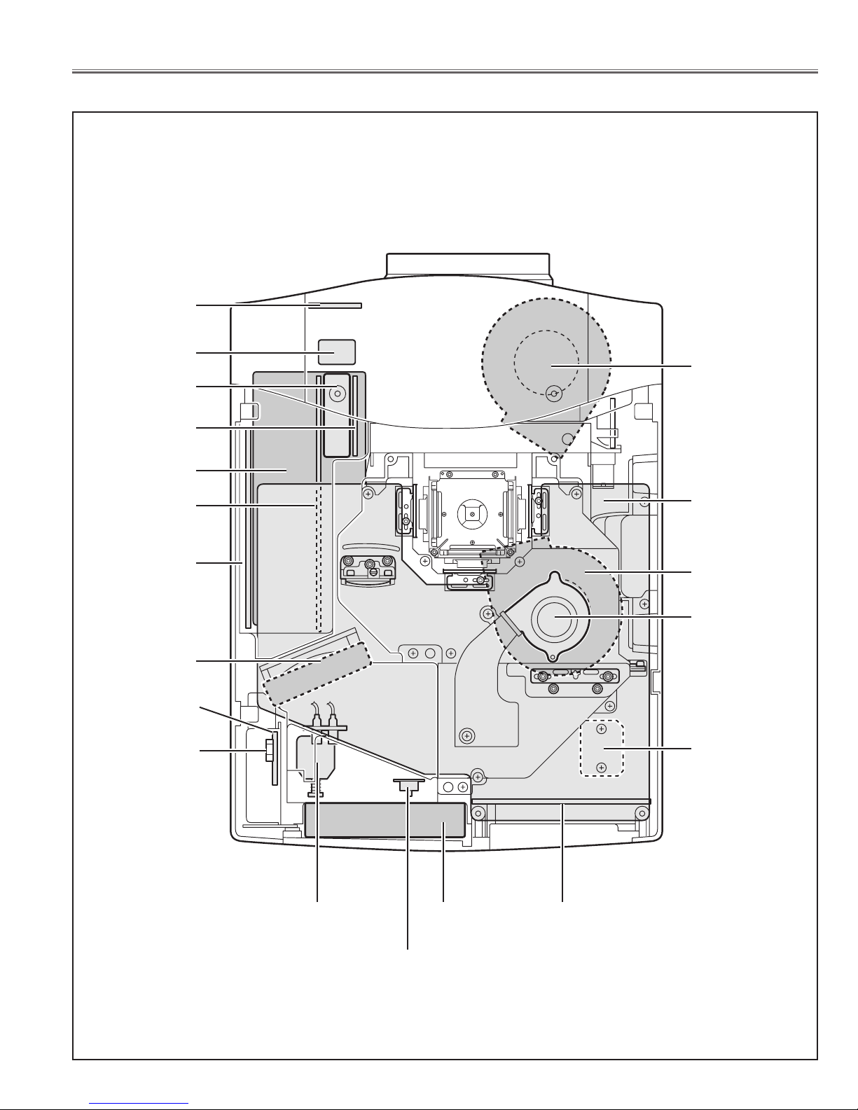
● OUT OF CIRCUIT BOARD
F601
Fuse
Power Board
Thermal Switch
(SW905)
Note: Parts order must contain Chassis No., Part No., and Descriptions.
FN901
Cooling Fan
Connect
Board
FN904
Cooling Fan
Interlock switch
(SW902)
Drive Board
RC1 Board
AV Board
Main Board
Line Filter
Board
Lamp Ballast
Board
FN902
Cooling Fan
FN905
Cooling Fan
Sensor1
Board
FN903
Cooling Fan
FN906
Cooling Fan
Sub Power
Board

MA8-XP4602/MA8-XP46L01
Electrical Parts List
-18-
! 610 293 1815 ASSY,PWB,CONTROL MA8A
! 610 293 1839 SSY,PWB,RC FRONT MA8A
! 610 293 1846 ASSY,PWB,CONNECT MA8A
! 610 294 8233 ASSY,PWB,SENSOR 1 MA8A
! 610 296 9351 ASSY,PWB,A/V MA8AA
! 610 296 9368 ASSY,PWB,I/F MA8AA
! 610 303 5185 ASSY,PWB,MAIN MK3A
! 610 316 4373 ASSY,PWB,POWER MK3AA
! 610 316 4380 ASSY,PWB,SUB POWER MK3AA
! 610 316 4397 ASSY,PWB,DRIVE MK3AA
! 610 316 4403 ASSY,PWB,FILTER MK3AA
!L901 645 003 3834 CORE,FERRITE
!L902 645 003 3834 CORE,FERRITE
!LF901 645 045 2154 UNIT,NOISE FILTER
!LP900 610 297 3891 COMPL,OPTICAL LAMP-MA8AA
!A901 645 051 9338 UNIT,BALLAST
!FN901 645 047 9700 MOTOR,FAN DC 11W
!FN902 645 047 9700 MOTOR,FAN DC 11W
!FN903 645 053 7523 MOTOR,FAN DC 1.68W
!FN904 645 053 7523 MOTOR,FAN DC 1.68W
!FN905 645 047 9489 MOTOR,FAN DC 5.28W
!FN906 645 048 4001 MOTOR,FAN DC 2.4W
!FN907 645 052 9313 MOTOR,FAN DC 2.04W
SP901 645 047 7584 SPEAKER,8
SP902 645 047 7584 SPEAKER,8
!SW902 645 031 7743 SWITCH,PUSH 2P-2TX2
!SW905 645 050 3580 SWITCH,THERMAL
W16I&8X 610 296 5476 CORD SHIELD 6P 1.5MM
W16M 610 296 0617 CONVERT CORD 4P
W16R&8T 645 050 4389 CORD,ID CONNECTOR
W16S&10T 645 051 7594 CORD,ID CONNECTOR
W28A&8U 645 050 4402 CORD,ID CONNECTOR
W66D&8D 645 049 4802 CORD,ID CONNECTOR
W66E&8E 645 049 4765 CORD,ID CONNECTOR
W66F&8G 645 050 4396 CORD,ID CONNECTOR
W66Q&66G 645 050 4372 CORD,ID CONNECTOR
W68A&8J 645 050 4426 CORD,ID CONNECTOR
W70A&8Q 645 053 7738 CORD,ID CONNECTOR
W70B&66N 645 053 7721 CORD,ID CONNECTOR
W70D&8Y 645 049 9081 CORD,ID CONNECTOR
W9B&16L 645 050 4358 CORD,ID CONNECTOR
W9C&8S 645 026 7017 CORD,ID CONNECTOR
WCN2&8W 645 026 7017 CORD,ID CONNECTOR
WK16M 645 039 9374 PLUG,RELAY 4P
ZA1001F2 411 002 0804 SCR BIN 4X6
ZA1001G 610 318 1219 GASKET DVI-MB8AB
ZA7001A 610 300 2095 GASKET PJNET-MA8AA
ZA7001B 610 300 2095 GASKET PJNET-MA8AA
610 293 1815 ASSY,PWB,CONTROL MA8A
CAPACITOR
C6871 403 164 0204 CERAMIC 0.1U Z 25V
C6881 403 164 0204 CERAMIC 0.1U Z 25V
C6891 403 164 0204 CERAMIC 0.1U Z 25V
C6892 403 164 0204 CERAMIC 0.1U Z 25V
RESISTOR
R6871 401 105 2904 MT-GLAZE 22K JA 1/16W
R6872 401 105 1600 MT-GLAZE 15K JA 1/16W
R6873 401 105 6001 MT-GLAZE 5.6K JA 1/16W
R6874 401 105 5301 MT-GLAZE 4.7K JA 1/16W
R6875 401 105 3307 MT-GLAZE 2.7K JA 1/16W
R6876 401 105 4106 MT-GLAZE 3.3K JA 1/16W
R6878 401 105 5202 MT-GLAZE 470 JA 1/16W
R6887 401 105 1501 MT-GLAZE 1.5K JA 1/16W
R6888 401 105 5202 MT-GLAZE 470 JA 1/16W
R6891 401 105 2904 MT-GLAZE 22K JA 1/16W
R6892 401 105 3802 MT-GLAZE 30K JA 1/16W
R6893 401 105 7909 MT-GLAZE 0.000 ZA 1/16W
R6894 401 105 7909 MT-GLAZE 0.000 ZA 1/16W
R6895 401 105 7909 MT-GLAZE 0.000 ZA 1/16W
R6896 401 105 7909 MT-GLAZE 0.000 ZA 1/16W
R6897 401 105 1501 MT-GLAZE 1.5K JA 1/16W
R6898 401 105 5202 MT-GLAZE 470 JA 1/16W
DIODE
D6871 407 223 0501 ZENER DIODE 02DZ12Y(TPH3)
D6872 407 223 0501 ZENER DIODE 02DZ12Y(TPH3)
D6881 407 223 0501 ZENER DIODE 02DZ12Y(TPH3)
D6891 407 223 0501 ZENER DIODE 02DZ12Y(TPH3)
D6892 407 203 7803 LED SML-210LT T86 M
D6893 407 203 7902 LED SML-210MT T86 M
D6894 407 203 7803 LED SML-210LT T86 M
D6895 407 203 7704 LED SML-210DT T86 L
MISCELLANEOUS
K68A 645 005 6970 PLUG,SIDE-ZR-SM3 9P
SW6871 645 026 2791 SWITCH,PUSH 1P-1TX1
SW6872 645 026 2791 SWITCH,PUSH 1P-1TX1
SW6873 645 026 2791 SWITCH,PUSH 1P-1TX1
SW6874 645 026 2791 SWITCH,PUSH 1P-1TX1
SW6875 645 026 2791 SWITCH,PUSH 1P-1TX1
SW6876 645 026 2791 SWITCH,PUSH 1P-1TX1
SW6878 645 026 2791 SWITCH,PUSH 1P-1TX1
SW6887 645 026 2791 SWITCH,PUSH 1P-1TX1
SW6888 645 026 2791 SWITCH,PUSH 1P-1TX1
SW6891 645 026 2791 SWITCH,PUSH 1P-1TX1
SW6892 645 026 2791 SWITCH,PUSH 1P-1TX1
SW6897 645 026 2791 SWITCH,PUSH 1P-1TX1
SW6898 645 026 2791 SWITCH,PUSH 1P-1TX1
610 293 1839 ASSY,PWB,RC FRONT MA8A
CAPACITOR
C2801 403 283 6309 CERAMIC 1U Z 10V
C2802 403 157 6206 CERAMIC 220P K 50V
C2803 403 304 2105 ELECT 47U M 6.3V
RESISTOR
R2801 401 105 0405 MT-GLAZE 100 JA 1/16W
R2802 407 225 0202 DIODE RB751S-40
R2803 401 105 7909 MT-GLAZE 0.000 ZA 1/16W
MISCELLANEOUS
AU2801 645 034 5029 UNIT,REMOCON RECEIVER
RC FRONT BOARD
CONTROL BOARD
OUT OF CIRCUIT BOARDS
ASSEMBLIED BOARDS
Key No. Part No. Description Key No. Part No. Description

MA8-XP4602/MA8-XP46L01
-19-
Electrical Parts List
610 293 1846 ASSY,PWB,CONNECT MA8A
610 294 8233 ASSY,PWB,SENSOR 1 MA8A
INTEGRATED CIRCUIT
IC1691 409 481 8602 IC LM76CHMX-5
CAPACITOR
C1691 403 281 5205 CERAMIC 0.22U Z 16V
C1692 403 155 1609 CERAMIC 33P J 50V
C1693 403 155 1609 CERAMIC 33P J 50V
RESISTOR
R1691 401 105 0405 MT-GLAZE 100 JA 1/16W
R1692 401 105 0306 MT-GLAZE 10 JA 1/16W
R1693 401 105 0306 MT-GLAZE 10 JA 1/16W
610 296 9351 ASSY,PWB,A/V MA8AA
TRANSISTOR
Q2001 405 134 5905 TR 2SA1037AK-T146-R
Q2002 405 134 5905 TR 2SA1037AK-T146-R
Q2003 405 134 5905 TR 2SA1037AK-T146-R
Q2004 405 014 4509 TR 2SC2412K T146 R
Q2006 405 014 4509 TR 2SC2412K T146 R
Q5007 405 014 4509 TR 2SC2412K T146 R
Q5008 405 014 4509 TR 2SC2412K T146 R
Q5201 405 014 4509 TR 2SC2412K T146 R
Q5202 405 014 4509 TR 2SC2412K T146 R
Q5203 405 014 4509 TR 2SC2412K T146 R
Q5204 405 014 4509 TR 2SC2412K T146 R
Q7262 405 014 4509 TR 2SC2412K T146 R
INTEGRATED CIRCUIT
IC101 409 470 2604 IC AD8183ARU-REEL7
IC1031 409 461 7304 IC AD8057ART-REEL7
IC1041 409 461 7304 IC AD8057ART-REEL7
IC1051 409 461 7304 IC AD8057ART-REEL7
IC3801 409 380 6303 IC HIN232CB
409 273 3501 IC SP232ACT
IC3802 409 395 5902 IC TC7SH00FU-(TE85L)
IC3803 410 296 5700 IC TWM7000-151020
IC3804 410 275 5806 IC TWM7000-162020
410 275 5707 IC TWM7000-162020
IC5001 409 051 2702 IC TC4052BF(EL)
IC5201 409 462 0304 IC 24LC21AT/SN
IC5202 409 051 2900 IC TC4053BF(EL)
IC5203 409 462 6009 IC AD8185ARU-REEL7
IC5204 409 407 7900 IC EL4332CS
IC7141 409 484 2003 IC BA7078AF-E2
IC7221 410 343 7008 IC SN74AHCT1G14DBVR
IC7222 410 343 7008 IC SN74AHCT1G14DBVR
CAPACITOR
C1004 403 164 0204 CERAMIC 0.1U Z 25V
C1006 403 164 0204 CERAMIC 0.1U Z 25V
C1007 403 304 2105 ELECT 47U M 6.3V
C1008 403 164 0204 CERAMIC 0.1U Z 25V
C1009 403 155 1609 CERAMIC 33P J 50V
C101 403 321 2607 ELECT 10U M 16V
C1011 403 164 0204 CERAMIC 0.1U Z 25V
C1012 403 155 1609 CERAMIC 33P J 50V
C1013 403 164 0204 CERAMIC 0.1U Z 25V
C1014 403 155 1609 CERAMIC 33P J 50V
C1016 403 164 0204 CERAMIC 0.1U Z 25V
C1017 403 304 2105 ELECT 47U M 6.3V
C1018 403 164 0204 CERAMIC 0.1U Z 25V
C102 403 321 2607 ELECT 10U M 16V
C1021 403 157 4202 CERAMIC 220P J 50V
C1022 403 283 6309 CERAMIC 1U Z 10V
C1023 403 304 2105 ELECT 47U M 6.3V
C1024 403 113 3805 CERAMIC 1000P K 50V
C1026 403 113 3805 CERAMIC 1000P K 50V
C1027 403 113 3805 CERAMIC 1000P K 50V
C1028 403 113 3805 CERAMIC 1000P K 50V
C103 403 321 2607 ELECT 10U M 16V
C104 403 164 0204 CERAMIC 0.1U Z 25V
C106 403 164 0204 CERAMIC 0.1U Z 25V
C107 403 164 0204 CERAMIC 0.1U Z 25V
C108 403 164 0204 CERAMIC 0.1U Z 25V
C109 403 149 9208 CERAMIC 0.01U Z 50V
C111 403 164 0204 CERAMIC 0.1U Z 25V
C112 403 280 1604 ELECT 220U M 16V
C113 403 164 0204 CERAMIC 0.1U Z 25V
C114 403 280 1604 ELECT 220U M 16V
C2007 403 149 9208 CERAMIC 0.01U Z 50V
C2008 403 304 3300 ELECT 47U M 16V
C2011 403 321 2607 ELECT 10U M 16V
C2012 403 321 2607 ELECT 10U M 16V
C2013 403 321 2607 ELECT 10U M 16V
C2014 403 164 0204 CERAMIC 0.1U Z 25V
C2016 403 321 2607 ELECT 10U M 16V
C2061 403 164 0204 CERAMIC 0.1U Z 25V
C2081 403 304 1801 ELECT 100U M 6.3V
C2082 403 304 1801 ELECT 100U M 6.3V
C2083 403 304 1801 ELECT 100U M 6.3V
C2086 403 283 6309 CERAMIC 1U Z 10V
C2087 403 283 6309 CERAMIC 1U Z 10V
C2088 403 229 3508 ELECT 100U M 16V
C2091 403 304 1801 ELECT 100U M 6.3V
C2092 403 304 1801 ELECT 100U M 6.3V
C3801 403 283 6309 CERAMIC 1U Z 10V
C3802 403 162 6208 ELECT 1U M 50V
C3803 403 162 6208 ELECT 1U M 50V
C3804 403 162 6208 ELECT 1U M 50V
C3807 403 283 6309 CERAMIC 1U Z 10V
C3808 403 283 6309 CERAMIC 1U Z 10V
C3809 403 283 6309 CERAMIC 1U Z 10V
C3811 403 283 6309 CERAMIC 1U Z 10V
C3812 403 162 6208 ELECT 1U M 50V
C3881 403 162 6208 ELECT 1U M 50V
C5003 403 323 8805 CERAMIC 2.2U Z 16V
C5004 403 323 8805 CERAMIC 2.2U Z 16V
C5006 403 323 8805 CERAMIC 2.2U Z 16V
C5007 403 323 8805 CERAMIC 2.2U Z 16V
C5008 403 323 8805 CERAMIC 2.2U Z 16V
C5009 403 323 8805 CERAMIC 2.2U Z 16V
C5011 403 323 1301 CERAMIC 0.47U Z 10V
C5012 403 323 1301 CERAMIC 0.47U Z 10V
C5013 403 304 3102 ELECT 22U M 16V
C5014 403 321 2607 ELECT 10U M 16V
C5016 403 323 1301 CERAMIC 0.47U Z 10V
C5204 403 164 0204 CERAMIC 0.1U Z 25V
C5207 403 283 6309 CERAMIC 1U Z 10V
C5208 403 283 6309 CERAMIC 1U Z 10V
A/V BOARD
SENSOR 1 BOARD
CONNECT BOARD
Key No. Part No. Description Key No. Part No. Description

MA8-XP4602/MA8-XP46L01
Electrical Parts List
-20-
C5209 403 304 2105 ELECT 47U M 6.3V
C5211 403 283 6309 CERAMIC 1U Z 10V
C5212 403 164 0204 CERAMIC 0.1U Z 25V
C5213 403 304 2105 ELECT 47U M 6.3V
C5214 403 149 9208 CERAMIC 0.01U Z 50V
C5216 403 283 6309 CERAMIC 1U Z 10V
C5217 403 164 0204 CERAMIC 0.1U Z 25V
C5218 403 304 2105 ELECT 47U M 6.3V
C5219 403 283 6309 CERAMIC 1U Z 10V
C5221 403 304 2105 ELECT 47U M 6.3V
C5226 403 157 3106 CERAMIC 56P J 50V
C5227 403 157 3106 CERAMIC 56P J 50V
C5228 403 157 3106 CERAMIC 56P J 50V
C5251 403 283 6309 CERAMIC 1U Z 10V
C5252 403 283 6309 CERAMIC 1U Z 10V
C5261 403 267 0606 NP-ELECT 4.7U M 16V
C5262 403 267 0606 NP-ELECT 4.7U M 16V
C5263 403 267 0606 NP-ELECT 4.7U M 16V
C5264 403 267 0606 NP-ELECT 4.7U M 16V
C5271 403 155 1500 CERAMIC 180P J 50V
C5272 403 155 1500 CERAMIC 180P J 50V
C5273 403 157 3809 CERAMIC 120P J 50V
C5274 403 157 3809 CERAMIC 120P J 50V
C5291 403 149 9208 CERAMIC 0.01U Z 50V
C7143 403 314 5905 CERAMIC 0.47U K 16V
C7144 403 314 5905 CERAMIC 0.47U K 16V
C7145 403 162 6208 ELECT 1U M 50V
C7146 403 314 5905 CERAMIC 0.47U K 16V
C7148 403 162 6604 ELECT 2.2U M 50V
C7149 403 162 6208 ELECT 1U M 50V
C7151 403 157 3601 CERAMIC 100P J 50V
C7152 403 164 0204 CERAMIC 0.1U Z 25V
C7153 403 304 1801 ELECT 100U M 6.3V
C7221 403 164 0204 CERAMIC 0.1U Z 25V
C7222 403 164 0204 CERAMIC 0.1U Z 25V
C7271 403 304 2105 ELECT 47U M 6.3V
C7272 403 283 6309 CERAMIC 1U Z 10V
RESISTOR
R1001 401 260 4102 MT-GLAZE 75 JA 1/3W
R1002 401 260 4102 MT-GLAZE 75 JA 1/3W
R1003 401 260 4102 MT-GLAZE 75 JA 1/3W
R1004 401 105 0405 MT-GLAZE 100 JA 1/16W
R1008 401 105 0405 MT-GLAZE 100 JA 1/16W
R1009 401 037 5004 MT-GLAZE 0.000 ZA 1/10W
R101 401 105 2904 MT-GLAZE 22K JA 1/16W
R1012 401 037 5004 MT-GLAZE 0.000 ZA 1/10W
R1014 401 037 5608 MT-GLAZE 10K JA 1/10W
R1016 401 037 5608 MT-GLAZE 10K JA 1/10W
R1017 401 105 0405 MT-GLAZE 100 JA 1/16W
R1018 401 105 0405 MT-GLAZE 100 JA 1/16W
R1019 401 260 4102 MT-GLAZE 75 JA 1/3W
R102 401 105 8104 MT-GLAZE 56K JA 1/16W
R1021 401 260 4102 MT-GLAZE 75 JA 1/3W
R1022 401 260 4102 MT-GLAZE 75 JA 1/3W
R1024 401 037 5004 MT-GLAZE 0.000 ZA 1/10W
R1027 401 037 5004 MT-GLAZE 0.000 ZA 1/10W
R1028 401 105 0405 MT-GLAZE 100 JA 1/16W
R1029 401 105 0405 MT-GLAZE 100 JA 1/16W
R103 401 105 2904 MT-GLAZE 22K JA 1/16W
R1031 401 105 0405 MT-GLAZE 100 JA 1/16W
R1032 401 105 0405 MT-GLAZE 100 JA 1/16W
R1033 401 105 0405 MT-GLAZE 100 JA 1/16W
R1038 401 105 0504 MT-GLAZE 1K JA 1/16W
R104 401 105 8104 MT-GLAZE 56K JA 1/16W
R1041 401 105 0504 MT-GLAZE 1K JA 1/16W
R1043 401 105 0504 MT-GLAZE 1K JA 1/16W
R1046 401 038 6604 MT-GLAZE 470K JA 1/10W
R1047 401 038 6604 MT-GLAZE 470K JA 1/10W
R1048 401 038 6604 MT-GLAZE 470K JA 1/10W
R1049 401 038 6604 MT-GLAZE 470K JA 1/10W
R1051 401 037 5004 MT-GLAZE 0.000 ZA 1/10W
R1052 401 037 5004 MT-GLAZE 0.000 ZA 1/10W
R1053 401 037 5004 MT-GLAZE 0.000 ZA 1/10W
R1054 401 037 5004 MT-GLAZE 0.000 ZA 1/10W
R1056 401 105 7909 MT-GLAZE 0.000 ZA 1/16W
R1057 401 105 7909 MT-GLAZE 0.000 ZA 1/16W
R1058 401 105 0405 MT-GLAZE 100 JA 1/16W
R106 401 105 2904 MT-GLAZE 22K JA 1/16W
R1061 401 105 0405 MT-GLAZE 100 JA 1/16W
R1062 401 105 7909 MT-GLAZE 0.000 ZA 1/16W
R1063 407 225 0202 DIODE RB751S-40
R107 401 105 8104 MT-GLAZE 56K JA 1/16W
R108 401 105 0405 MT-GLAZE 100 JA 1/16W
R109 401 105 0405 MT-GLAZE 100 JA 1/16W
R111 401 105 0405 MT-GLAZE 100 JA 1/16W
R112 401 105 0405 MT-GLAZE 100 JA 1/16W
R113 401 105 0405 MT-GLAZE 100 JA 1/16W
R114 401 105 0405 MT-GLAZE 100 JA 1/16W
R122 401 105 0504 MT-GLAZE 1K JA 1/16W
R123 401 105 3901 MT-GLAZE 33 JA 1/16W
R124 401 105 3901 MT-GLAZE 33 JA 1/16W
R126 401 105 3901 MT-GLAZE 33 JA 1/16W
R2001 401 260 4102 MT-GLAZE 75 JA 1/3W
R2002 401 260 4102 MT-GLAZE 75 JA 1/3W
R2003 401 260 4102 MT-GLAZE 75 JA 1/3W
R2004 401 260 4102 MT-GLAZE 75 JA 1/3W
R2005 401 260 4102 MT-GLAZE 75 JA 1/3W
R2006 401 037 5202 MT-GLAZE 100 JA 1/10W
R2008 401 105 0603 MT-GLAZE 10K JA 1/16W
R2009 401 105 5400 MT-GLAZE 47K JA 1/16W
R2011 401 105 0504 MT-GLAZE 1K JA 1/16W
R2012 401 105 7909 MT-GLAZE 0.000 ZA 1/16W
R2013 401 105 2904 MT-GLAZE 22K JA 1/16W
R2014 401 105 5400 MT-GLAZE 47K JA 1/16W
R2016 401 105 0504 MT-GLAZE 1K JA 1/16W
R2017 401 105 7909 MT-GLAZE 0.000 ZA 1/16W
R2018 401 105 2904 MT-GLAZE 22K JA 1/16W
R2019 401 105 5400 MT-GLAZE 47K JA 1/16W
R2021 401 105 0504 MT-GLAZE 1K JA 1/16W
R2022 401 105 2904 MT-GLAZE 22K JA 1/16W
R2023 401 105 7909 MT-GLAZE 0.000 ZA 1/16W
R2024 401 105 5400 MT-GLAZE 47K JA 1/16W
R2026 401 105 5400 MT-GLAZE 47K JA 1/16W
R2027 401 105 7909 MT-GLAZE 0.000 ZA 1/16W
R2028 401 105 5400 MT-GLAZE 47K JA 1/16W
R2029 401 105 0504 MT-GLAZE 1K JA 1/16W
R2031 401 105 5400 MT-GLAZE 47K JA 1/16W
R2032 401 105 7909 MT-GLAZE 0.000 ZA 1/16W
R2033 401 105 0504 MT-GLAZE 1K JA 1/16W
R2034 401 038 6604 MT-GLAZE 470K JA 1/10W
R2036 401 038 6604 MT-GLAZE 470K JA 1/10W
R2039 401 037 5202 MT-GLAZE 100 JA 1/10W
R2041 401 037 5202 MT-GLAZE 100 JA 1/10W
R2044 401 037 5202 MT-GLAZE 100 JA 1/10W
R2046 401 105 0603 MT-GLAZE 10K JA 1/16W
R2047 401 105 4007 MT-GLAZE 330 JA 1/16W
R2062 401 105 2805 MT-GLAZE 2.2K JA 1/16W
R2070 401 037 5400 MT-GLAZE 1K JA 1/10W
R2074 401 037 5004 MT-GLAZE 0.000 ZA 1/10W
R3801 401 105 0405 MT-GLAZE 100 JA 1/16W
R3802 401 105 7909 MT-GLAZE 0.000 ZA 1/16W
R3803 401 105 5509 MT-GLAZE 470K JA 1/16W
R3804 401 105 0405 MT-GLAZE 100 JA 1/16W
R3806 401 105 7909 MT-GLAZE 0.000 ZA 1/16W
Key No. Part No. Description Key No. Part No. Description

MA8-XP4602/MA8-XP46L01
-21-
Electrical Parts List
R3807 401 105 7909 MT-GLAZE 0.000 ZA 1/16W
R3814 401 105 0603 MT-GLAZE 10K JA 1/16W
R3816 401 105 0405 MT-GLAZE 100 JA 1/16W
R3817 401 105 0405 MT-GLAZE 100 JA 1/16W
R3818 401 105 0603 MT-GLAZE 10K JA 1/16W
R3819 401 105 4205 MT-GLAZE 33K JA 1/16W
R3821 401 105 7909 MT-GLAZE 0.000 ZA 1/16W
R3822 401 105 0603 MT-GLAZE 10K JA 1/16W
R3823 401 105 0603 MT-GLAZE 10K JA 1/16W
R3824 401 105 7909 MT-GLAZE 0.000 ZA 1/16W
R3826 401 105 0603 MT-GLAZE 10K JA 1/16W
R3827 401 105 0405 MT-GLAZE 100 JA 1/16W
R3828 401 105 0603 MT-GLAZE 10K JA 1/16W
R3829 401 105 0603 MT-GLAZE 10K JA 1/16W
R3831 401 105 7909 MT-GLAZE 0.000 ZA 1/16W
R3832 401 105 7909 MT-GLAZE 0.000 ZA 1/16W
R5009 401 105 4106 MT-GLAZE 3.3K JA 1/16W
R5011 401 105 4106 MT-GLAZE 3.3K JA 1/16W
R5012 401 105 0405 MT-GLAZE 100 JA 1/16W
R5013 401 105 0405 MT-GLAZE 100 JA 1/16W
R5014 401 105 7909 MT-GLAZE 0.000 ZA 1/16W
R5016 401 105 7909 MT-GLAZE 0.000 ZA 1/16W
R5017 401 105 2003 MT-GLAZE 1.8K JA 1/16W
R5018 401 105 2003 MT-GLAZE 1.8K JA 1/16W
R5019 401 105 0405 MT-GLAZE 100 JA 1/16W
R5021 401 105 0405 MT-GLAZE 100 JA 1/16W
R5201 401 105 0405 MT-GLAZE 100 JA 1/16W
R5202 401 105 0405 MT-GLAZE 100 JA 1/16W
R5203 401 105 0405 MT-GLAZE 100 JA 1/16W
R5204 401 037 5608 MT-GLAZE 10K JA 1/10W
R5206 401 105 0405 MT-GLAZE 100 JA 1/16W
R5207 401 105 0405 MT-GLAZE 100 JA 1/16W
R5208 401 105 0801 MT-GLAZE 12 JA 1/16W
R5209 401 105 0801 MT-GLAZE 12 JA 1/16W
R5211 401 105 0801 MT-GLAZE 12 JA 1/16W
R5212 401 105 2607 MT-GLAZE 22 JA 1/16W
R5213 401 105 2607 MT-GLAZE 22 JA 1/16W
R5215 401 105 2607 MT-GLAZE 22 JA 1/16W
R5216 401 105 0702 MT-GLAZE 100K JA 1/16W
R5217 401 105 0702 MT-GLAZE 100K JA 1/16W
R5218 401 105 0702 MT-GLAZE 100K JA 1/16W
R5219 401 105 1402 MT-GLAZE 150 JA 1/16W
R5221 401 258 9904 MT-GLAZE 10 JA 1/3W
R5223 401 105 1402 MT-GLAZE 150 JA 1/16W
R5224 401 105 1402 MT-GLAZE 150 JA 1/16W
R5226 401 105 0405 MT-GLAZE 100 JA 1/16W
R5227 401 105 0603 MT-GLAZE 10K JA 1/16W
R5228 401 105 0603 MT-GLAZE 10K JA 1/16W
R5229 401 105 0603 MT-GLAZE 10K JA 1/16W
R5231 401 105 0504 MT-GLAZE 1K JA 1/16W
R5233 401 105 0603 MT-GLAZE 10K JA 1/16W
R5271 401 105 0702 MT-GLAZE 100K JA 1/16W
R7147 401 105 8005 MT-GLAZE 1M JA 1/16W
R7148 401 105 4601 MT-GLAZE 3.9K JA 1/16W
R7221 401 105 1303 MT-GLAZE 15 JA 1/16W
R7222 401 105 1303 MT-GLAZE 15 JA 1/16W
R7223 401 105 7909 MT-GLAZE 0.000 ZA 1/16W
R7224 401 105 7909 MT-GLAZE 0.000 ZA 1/16W
R7227 401 105 0405 MT-GLAZE 100 JA 1/16W
R7229 401 105 0405 MT-GLAZE 100 JA 1/16W
R7266 401 105 0603 MT-GLAZE 10K JA 1/16W
R7267 401 105 0603 MT-GLAZE 10K JA 1/16W
R7273 401 105 7909 MT-GLAZE 0.000 ZA 1/16W
R7293 401 105 0405 MT-GLAZE 100 JA 1/16W
RB3801 645 025 5380 R-NETWORK 10KX4 1/16W
645 026 8014 R-NETWORK 10KX4 1/16W
RB5001 645 026 8021 R-NETWORK 100KX4 1/16W
RB5002 645 026 8021 R-NETWORK 100KX4 1/16W
COIL
L1001 645 024 0669 FILTER,EMI 20PF
L1002 645 024 0669 FILTER,EMI 20PF
L1003 645 024 0669 FILTER,EMI 20PF
L1004 645 044 8843 FILTER,EMI 200MHZ
L1006 645 044 8843 FILTER,EMI 200MHZ
L1007 645 024 0669 FILTER,EMI 20PF
L1008 645 024 0669 FILTER,EMI 20PF
L1009 645 024 0669 FILTER,EMI 20PF
L1011 645 044 8843 FILTER,EMI 200MHZ
L1012 645 044 8843 FILTER,EMI 200MHZ
L1013 645 045 6183 FILTER,EMI 25MHZ
L1014 645 045 6183 FILTER,EMI 25MHZ
L1016 645 045 6183 FILTER,EMI 25MHZ
L1017 645 045 6183 FILTER,EMI 25MHZ
L1018 645 045 6183 FILTER,EMI 25MHZ
L1019 645 045 6183 FILTER,EMI 25MHZ
L102 401 035 4306 MT-GLAZE 10 JA 1/8W
L1021 645 045 6183 FILTER,EMI 25MHZ
L1022 645 045 6183 FILTER,EMI 25MHZ
L1023 645 045 6183 FILTER,EMI 25MHZ
L1024 645 045 6183 FILTER,EMI 25MHZ
L1026 645 045 6183 FILTER,EMI 25MHZ
L2001 401 035 4108 MT-GLAZE 0.000 ZA 1/8W
L2002 401 035 4108 MT-GLAZE 0.000 ZA 1/8W
L2003 401 035 4108 MT-GLAZE 0.000 ZA 1/8W
L2004 401 035 4108 MT-GLAZE 0.000 ZA 1/8W
L2006 401 035 4108 MT-GLAZE 0.000 ZA 1/8W
L2007 645 044 8836 FILTER,EMI 100MHZ
L2008 645 044 8836 FILTER,EMI 100MHZ
L2009 645 044 8836 FILTER,EMI 100MHZ
L2011 645 044 8836 FILTER,EMI 100MHZ
L2012 645 044 8836 FILTER,EMI 100MHZ
L2013 645 045 6183 FILTER,EMI 25MHZ
L2014 645 045 6183 FILTER,EMI 25MHZ
L2015 645 045 6183 FILTER,EMI 25MHZ
L2018 645 045 6183 FILTER,EMI 25MHZ
L2019 645 045 6183 FILTER,EMI 25MHZ
L5201 401 035 4108 MT-GLAZE 0.000 ZA 1/8W
L5202 401 035 4108 MT-GLAZE 0.000 ZA 1/8W
DIODE
D1001 407 209 1201 ZD UDZS-TE-176.2B
D1002 407 209 1201 ZD UDZS-TE-176.2B
D1003 407 209 1201 ZD UDZS-TE-176.2B
D1004 407 209 1201 ZD UDZS-TE-176.2B
D1006 407 209 1201 ZD UDZS-TE-176.2B
D1007 407 209 1201 ZD UDZS-TE-176.2B
D1008 407 221 7106 ZENER DIODE UDZS-TE-1712B
D1009 407 221 7106 ZENER DIODE UDZS-TE-1712B
D1011 407 201 2701 DIODE RB051L-40-TE25
D1012 407 221 7106 ZENER DIODE UDZS-TE-1712B
D1013 407 221 7106 ZENER DIODE UDZS-TE-1712B
D1014 407 209 1201 ZD UDZS-TE-176.2B
D1016 407 209 1201 ZD UDZS-TE-176.2B
D1017 407 209 1201 ZD UDZS-TE-176.2B
D1018 407 209 1201 ZD UDZS-TE-176.2B
D1019 407 209 1201 ZD UDZS-TE-176.2B
D1021 407 209 1201 ZD UDZS-TE-176.2B
D1022 407 209 1201 ZD UDZS-TE-176.2B
D1023 407 209 1201 ZD UDZS-TE-176.2B
D1024 407 209 1201 ZD UDZS-TE-176.2B
D1026 407 209 1201 ZD UDZS-TE-176.2B
D1027 407 209 1201 ZD UDZS-TE-176.2B
D1028 407 209 1201 ZD UDZS-TE-176.2B
D1029 407 209 1201 ZD UDZS-TE-176.2B
Key No. Part No. Description Key No. Part No. Description
 Loading...