

Sanyo PLC-XP21N,PLC-XP21E,PLC-XP21B Service
Notice
n
CORRECTION
[B
PRODUCTION
CHANGE
EJ
SERVICE
FLASH
El!
ADD
INFORMATION
Please
add
this
notice
to
the
Service
Manuals
listed
below.
Revision
1
Category
:
Model
No.:
Destination:
Multimedia
projector
PLC-XP21N
PLC-XP21E
PLC-XP21B
U.S.A-.
Canada
Europe.
Asia.
Africa,
M.E.
U.K.
(PLC-XP2tN)
(PLC-XP21E)
(PLC-XP21B)
Date:
Effective
from
Chassis
No.
Ref.
No.:
Mar./2001
MF&.XP21N01
PLC-XP21E01
PLC-XP21B01
SM5H0202
Give
complete
"CHASSIS
NO."
for
parts
order
or
servicing,
it
is
shown
on
the
rating
sheet
on
the
cabinet
of
the
Projector.
NOTE:
This
service
manual
is
production
change
notice,
but
not
dif-
ference
service
information
and
New
version
from
chassis
no.
MF6-XP21N01,
PLC-XP21E01
and
PLC-XP21BOL
W
CONTENTS
Specifications
DtsassemMies
and
Reptacement
Procedures
Machanicai
disassemblies
Opttcat
untt
disassembles
LCD
pane!
replacement
Assy
!amp
t'eptacetDent
Safety
fnstructiorts
Cfrcurt
Protections
TrouMeshooting
Wa^/e^rms
Atignmont
Procedures
Service
adjustments
BectJicai
adjustment
Focus
adjustments
Convergence
adjustment
2
3-17
3-8
9-14
15
16-17
18
19
20-27
28-29
30-43
31-32
33-37
38-39
40
integrator
iens
adjustment
Reiay
tens
adjustment
Polarized
glass
adjustment
CPU
input/output
port
functions
Maintenance
Notes
on
scnemaSc
diagram
Parts
Ust
Cabinet,
Chassis
and
Optical
parts
itst
Eiectnca)
parts
iist
Parts
location
and
PWB
pattern
diagrams
Btock
diagram
and
Low
power
dtstrtbution
Schematic
diagrams
41
42
43
44-47
48-49
50-51
52-79
54-58
59-79
P1-P3
61
S1-S8
PRODUCT
CODE
112207370:(MF6AA)
112207470:(PF6AA)
112207472:(PF6CA)
REFERENCE
NO.
SM5110202-01
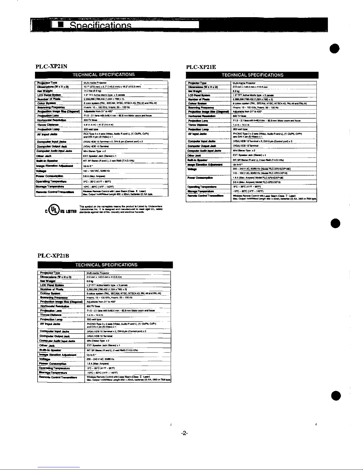
PLC-XP21N
PLC-XP21E
TECHN)CAL
SPECtF)CAT)ONS
TECHN)CAL
SPEC)F)CAT)ONS
Pmt-otofTypt
M)tMf-tcn<(W]tH:tt))
HMWttNM
LCOt^MOf^m
tttmtXtrofPHttt
Cater
OMfM
aefn)n(tf^qu<MCt
n
ot^M^nn
how
*'^
CfH^o"^
Prf)ftottML*M
m<n^t<m
ttM^'<)M
nwowDM——
PrB)<o<tML)X^
AVtnput^^
Omtt)tt<tf
ttput
JMc*
ee<Mpm-rOtX^tJt)et
CempHMf*Mao!nputJ^*
OWMfJ-*
fMnapt^m^
ttO«(t<HB-^aoM(t-h))-nt
WXt^tt
)^^rCc^-^t-.
Opt^t^T-Hp^^,
atom^TtmptMMw
^^.C^.T^^-.
M^-mttM
Pmt*oo'
10
7-
<272
tnm) ^ 6.?-
(145^
'w)'
K.2*
(4I2.S
mm)
mx^e.ete!
t.3-T)^T'tc'h^M^htyp*
tSptnttt
!.35<^M
f7M.43Z
ft.fa'H
7M).
3)
6
cotOf
t^tm
tPM-.
SECAM.
MTSC.
MTSC<.<^
PM--M
tntt
R^.-W)
H-^ne.
'S - 100
KHt
V-wv:. M '
'CO
m
*<tt-ttHth<im3''<t)400-
F1.a-:.1'*^'!Wt-4e.*'nm-M.e'nm'*<!).
mnuMdticu.
aooTVtntt
<.^t'.<m)-47.T<K.4m)
MOM<tWt
^D^^^^^^^^^
fVaA)HDe':T^m!^^:.DM<pM(Camfo)peft)^2
fVOA^HOatST^m^
Mh.S'^o1^p..S
E)cr.sp*^*fJ*^fatMo)ti
)HT. M S^m)
jR
md
L),:
f^)
RM9
{T.H.D.10%)
UfKot'
^-IMVAC.SMNHz
3.AfM^.An^.)
S'C - M'C
f4t°F - M*F)
-1[fC-efrCft<'F-t*0°F)
MM.Omp^tmWW^t^nt*'esO±Mnm.MmtnttMAAWt.
PntftottfTypt
D)mtnOam<(W^Mta)
MMWj^t
[.Ctt!^^t)f'ttM
tt')mHtfatPh<tf
Catexftjtm))
t^t^fn^no^
rrm)tnt<on
tn'm
Mm
(!H*))nn^)
ThM^Btt^nat
f^ftNteoUM^
jM'))))^J«ft^
ComtMMfH)tMtJ))(*t
C<^t)M-(MtMtA^
Cc''w"<"*M!h!HtM*Mt*
OtMfjMt
'^Untp^'r
^Mt^
fJMfrMMM^Xtno
QtM^T-nptt^iM
m^tT^jomxF)
tt^C^MT
MuM-'ntdtPffttCtor
!72nm"4S.!mn'):<tZ.5nm
6.9ka
1.3'TPTAO)ttMt)^tH)t
!.3pt!nt^
2.3M^<
;7M,43:
(1.0M
jt
7M)
13)
e
eo'OM
t^tm
(P)U..
SECAM.
MTSC,
NT9C4.^.
HU--^
md
PM.-N)
tKt^'S'1MK^.V<v^:M-HCMf
A«mttMttrem3t'to^OO'
MOTV^ntt
F)^-X1)tntfM"^t.4mm-M.emmMot«toon'tm<tMtt
1.4m-t*.*m
200M)tt)H-
PHONO'!^i)t2tttttVX)to.*))OH(Htn<fU.(Y.CM^.C^P^
tVaA)MOet9T.mtnt)tt.DtHt)i)r.<Cmtm)pomjt:
(V(M^HDet5Ttnn'nM
M^St^)-^..^
EXT.
Spt^ttJte^fStt^o)).)
!Mr.SP.S'Me)RtndL).2tMiRMafT.H.[l1M.)
Uttoe'
200-MOVAC,MMOH!(Mo<MPLC-XM1E/XPteE)
t'O - tZOV ^ MM m f'*)d*tPt.&.XM''XPH)
l.t A fMtt.
Amptft)
Mod*)
PLC-XKI&XPttE
MA(Mt..AmpM)MeOttt^MMt/)(Pia
S-C-3!(-Cf<1-F-M-F)
.ttrc-M^fM'F-t^O^
)M^ttt'ttmottCmM')tmL*tttBttm(attt n Lttt^
tHt t ..M..,.
L^Xmttt^tfM!. t tdtt'anMf*n.)n^nut^±j^ammMf'eMtiL.ttttt/
G ^ ^/
HS
mttB
mmf)eWo*'ntt'Wo"^cmuo^t-^*^e'ne^h-z-t^
PLC-XP21B
TECHNtCAL
SPEOFtCATfONS
P'<^ctefTyp<
Dtt««n)t)ont(W);H!<[^
MMW^^tt
LCD
P)MM<
0)^-0
MtMNbtrofMMtt
Qete^tj!M)!')
<<Mmntn))R<qu<nef
t^f^OtOM
!mt))t
NtM
(Dftten^
MatteonMM^tXMttM
P'^tM^nL*^
TttftxofM'tMC*
PTnf^onD)mp
AWtHpMJ^f
Campt<t<r)n^)tJ^t.t
CB'Mt<tt)trOmpMJ))e)t
Cot))pt^rA<x^!ot«Jt^*
Othtf^ett
Bm^tnapottf
fnma*
ritftHnn
*^«t«<^«
Wa'Mto'
Po-M-ConttMpMM'
Optf*MneT<mp*MtuM
^ofO<T*mp*^tun'
B*mqtt
CMtmi
Tt^tt^ttM
MtjHUn^PmttCto.
!7:
n<t) j I4S.S
mm . 4)2.5
mn
e.9^
t.3'TFr<MMMt<tftK)t
):3ptnet
Z,3M^M
[TM.43^
ft
.OM
)t
7M) < 3)
a
t^om
t^tttm
(P^
SECAM.
'<TaC.
MTSM.O.
PM.-M
md
PM.-M)
tt<ync.'5-'MmHz.V^ne.M-IM)m
Af!jDtMtmim3^'to<00-
aootvnMt
F1.a-2.1Mxm'-M.*"m-M.emmM[<ormmtnt)tM
1.<m-'<.<m
200w*tttH)t
PHONO'^ptS^ZMM
(VMM.
Attdk)Rt^L).fY.CM^.CnPr)
(VaA)HOB1STtm^i.?.D)Mtp^<CtMm'pon)<Z
(VQA)HOB15TtmMi
MntSMtoTtpt
)!2
EfT.Sp**)-.JM.fS!^)).t
fMT
Sf
S<Mt)
(H
tnd
L).:
^^tt
HMS
F.H.n'M.)
UpM6'
ZOO'MOVAC.M^OMt
t.NAfM-t.Ampm)
S°C-3S'C(4^°F^96f)
-t(t-C-eO-C(K'F-'40f)
M^OuqM1mW^^tLtne)h6Ml2()nm.btttMtt(2t**.UM<i'Hoe)te*
Mechanica)
disassemble
shoutd
be
made
foUowing
procedures
in
numertcai
order.
Foitowtng
steps
show
the
basic
procedures,
therefore
unnecessary
step
may
be
ignored.
Cautton:
The
parts
and
screws
shoutd
be
placed
exactty
the
same
posftton
as
the
origina)
otherwise H may
cause
toss
of
per-
formance
and
product
safety
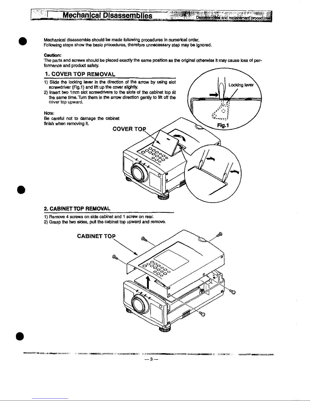
1.
COVER
TOP
REMOVAL
1)
S)kte
the
)ocking
)evsr
in
the
direction
of
the
arrow
by
using
slot
screwdriver
(Fig.1)
and
tift
up
the
cover
sttghtty.
2)
tnseft
two
1mm
s!ot
screwdrivers
to
the
siots
of
the
cabinet
top
at
the
same
time.
Turn
them
in
the
arrow
direction
gontty
to
!tft
off
the
cover
top
upward.
Note:
Be
carefui
not
to
damage
the
cabinet
finish
when
removing
M.
COVER
TOR
2.
CABINET
TOP
REMOVAL
1)
Remove 4 screws
on
side
cabinet
and 1 screw
on
rear.
2)
Grasp
the
two
stdes.
pu)i
the
cabinet
top
upward
and
remove.
CABLET
TOP
^
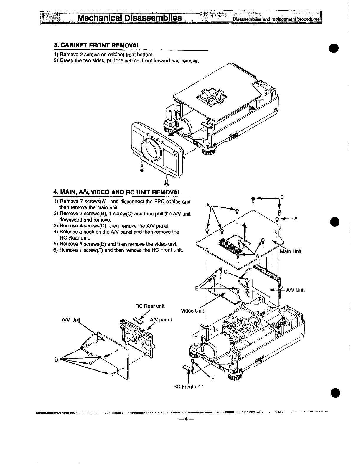
3.
CAB)NET
FRONT
REMOVAL
1)
Remove 2 screws
on
cabinet
front
bottom.
2)
Grasp
the
two
sfdes,
putt
the
cabinet
front
forward
and
remove.
RC
Front
unit
—4
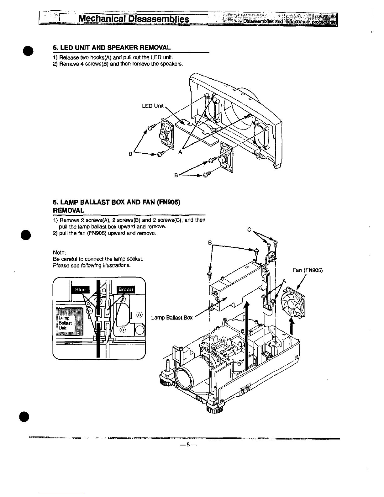
5.
LED
UNIT
AND
SPEAKER
REMOVAL
1)
Refease
two
hooks(A)
and
put)
out
the
LED
unrt.
2)
Remove 4 screws(B)
arnj
then
remove
the
speakers.
6.
LAMP
BALLAST
BOX
AND
FAN
(FN905)
REMOVAL
1)
Remove 2 screws(A),
2
screws(B)
and 2 screws(C).
and
then
put)
the
iamp
bat(ast
box
upward
and
remove.
2)
pu)!
the
fan
(FN905)
upward
and
remove.
Note:
Be
carefu)
to
connect
the
tamp
socket.
Ptease
see
fottowing
i))ustrattons.
Lamp
—5—
Fan
(FN905)
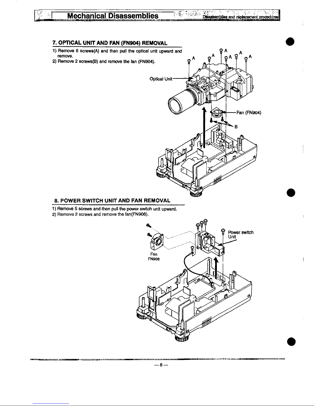
7.
OPDCAL
UN)T
AND
FAN
(PN904)
REMOVAL
1)
Remove 6 screws(A)
and
then
pu!)
the
optica)
unit
upward
and
femove.
2)
Remove 2 screws(B)
and
remove
the
fan
(FN904).
8.
POWER
SWrrCH
UN)TAND
FAN
REMOVAL
1)
Remove 5 screws
and
then
puf)
the
power
swrtch
unit
upward.
2)
Remove 2 screws
and
remove
the
fan(FN906).
Mechanica)
Dtsassembties
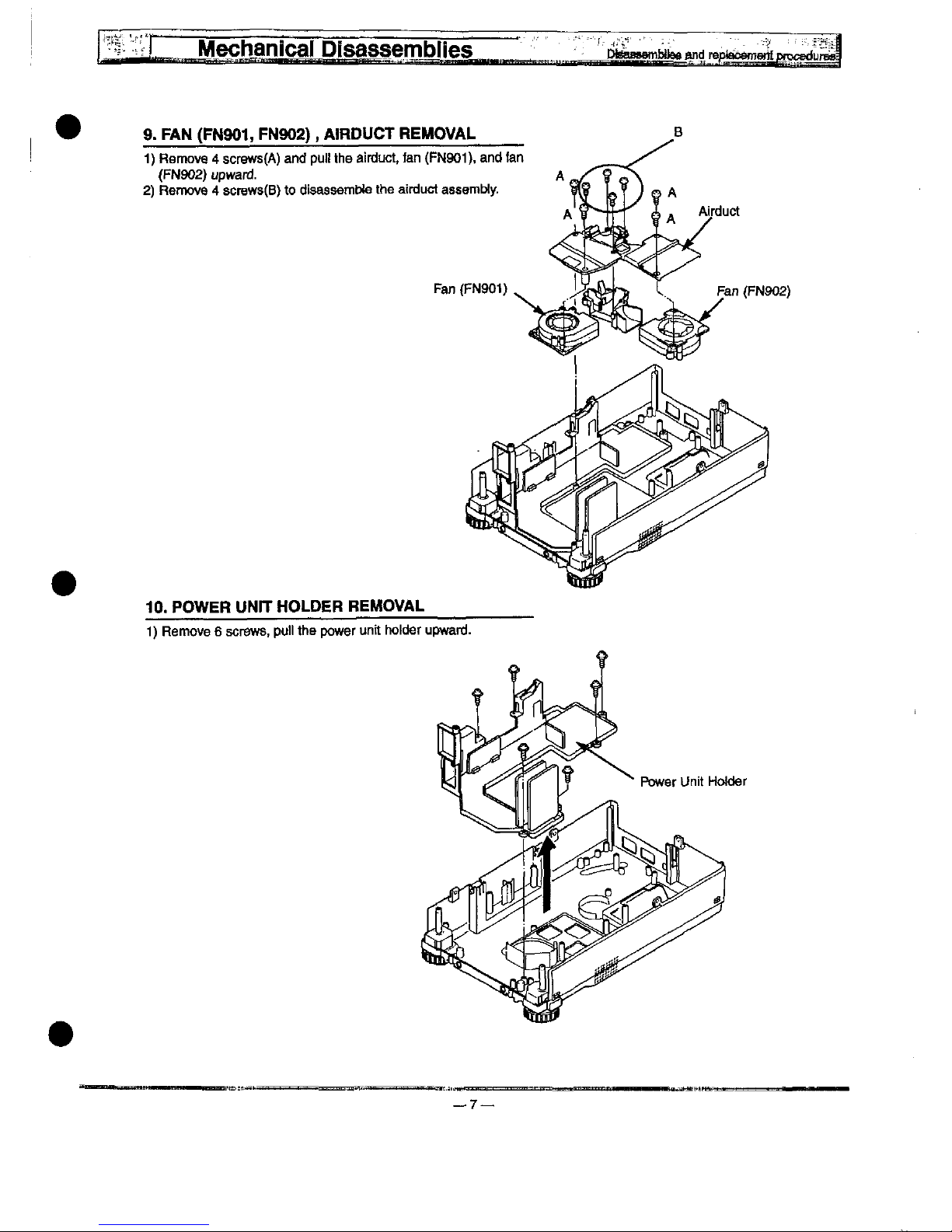
9.
FAN
(PNM^
FN902),
A!RDUCT
REMOVAL
1)
Remove 4 screws(A)
and
pu)!
the
airduct,
fan
(FN901).
and
fan
(FN902)
upward.
2)
Remove 4 screws(B)
to
disassembte
the
airduct
assembty.
Fan
(FN901)
Fan
(FN902)
10.
POWER
UNrr
HOLDER
REMOVAL
1)
Remove 6 screws,
pu))
the
power
unit
hokter
upward.
Power
Unit
Hofder
Mechanica)
Disassembles
^^MnMtee
and
'^a<^^
M^^^
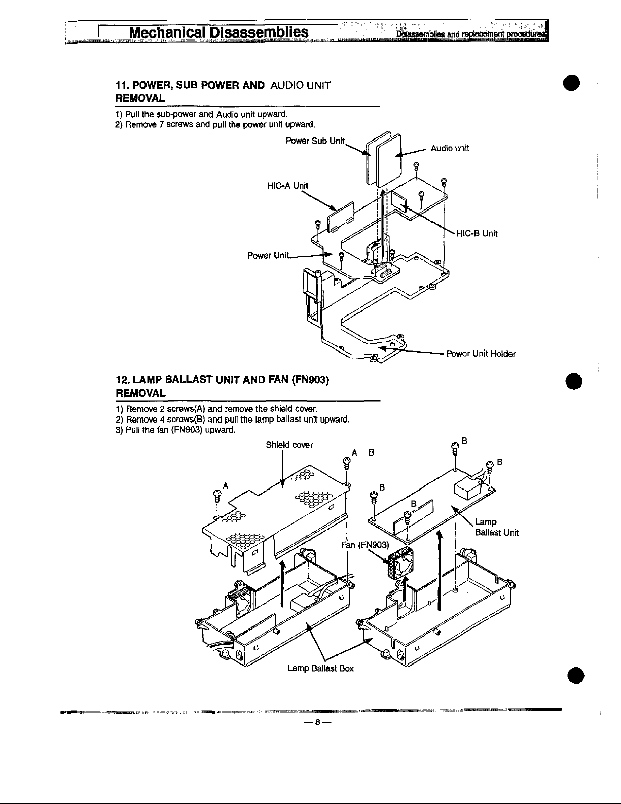
11.
POWER,
SUB
POWER
AND
AUD)0
UN)T
REMOVAL
1)
Pufi
the
sub-power
and
Audio
unit
upward.
2}
Remove 7 screws
and
pu)!
the
power
unit
upward.
HtC-A
Unit
Power
Uni
Audio
unit
HiC-B
Unrt
Power
Unit
Hotder
12.
LAMP
BALLAST
UN!T
AND
FAN
(FN903)
REMOVAL
1)
Remove 2 screws(A)
and
remove
the
shie)d
cover.
2)
Remove 4 screws(B)
and
puit
the
tamp
batiast
unit
upward.
3)
Pu)i
the
fan
(FN903)
upward.
Lamp
Baftast
Box
—8—

DtMMOfnbHes
and
repta&Mnent
prc^dur
Remove
the
cabinet,
cabinet
front,
main,
video
and
A/V
unit
fottow-
ing
to
steps 2 to 4 of
"Mechanicat
Disassembles".
1.
LENS
ASSY
REMOVAL
1)
Remove 4 screws
and
remove
the
tens
assy.
Fig.1
2.
RELAY
LENS
AND
INTEGRATOR
LENS
AND
POLARtZED
GLASS-)N
R,
G, B REMOVAL
1)
Remove 2 screws(A)
and
then
putt
the
retay
tens
upward.
2)
Remove 2 screws(B)
and
then
putt
the
integrator
tens
upward.
3)
Remove
each
screw(C)
and
then
putt
the
polarized
giass-in
R,
G,
B
upward.
Polarized
Gtass-tN
(G)
Pofarized
Gtass-)N
(R)
Pofarized
Gtass-tN
(B)
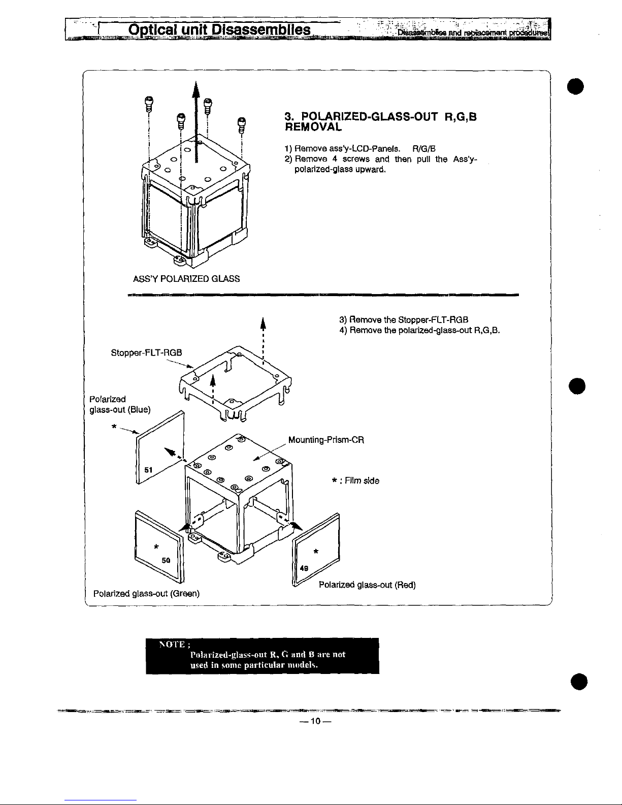
3.
POLARtZED-GLASS-OUT
R,G,B
REMOVAL
1)
Remove
ass'y-LCD-Panefs.
R/G/B
2)
Remove 4 screws
and
then
pu))
the
Ass'y-
po)arized-g)ass
upward.
ASS'Y
POLAR)ZED
GLASS
3)
Remove
the
Stoppor-FLT-RGB
4)
Remove
the
po)arized-g)ass-out
R.G.B.
Pofarfzad
gtass-out
(B!ue)
Mounting-Prism-CR
*:
Fi!m
stde
Po)arized
gtass-out
(Green)
Po)arized
gtass-out
(Red)
?<OTE;
Pn!arized-gt.i^-out
R, G and B are
not
used
in
some
particufar
models.
10—
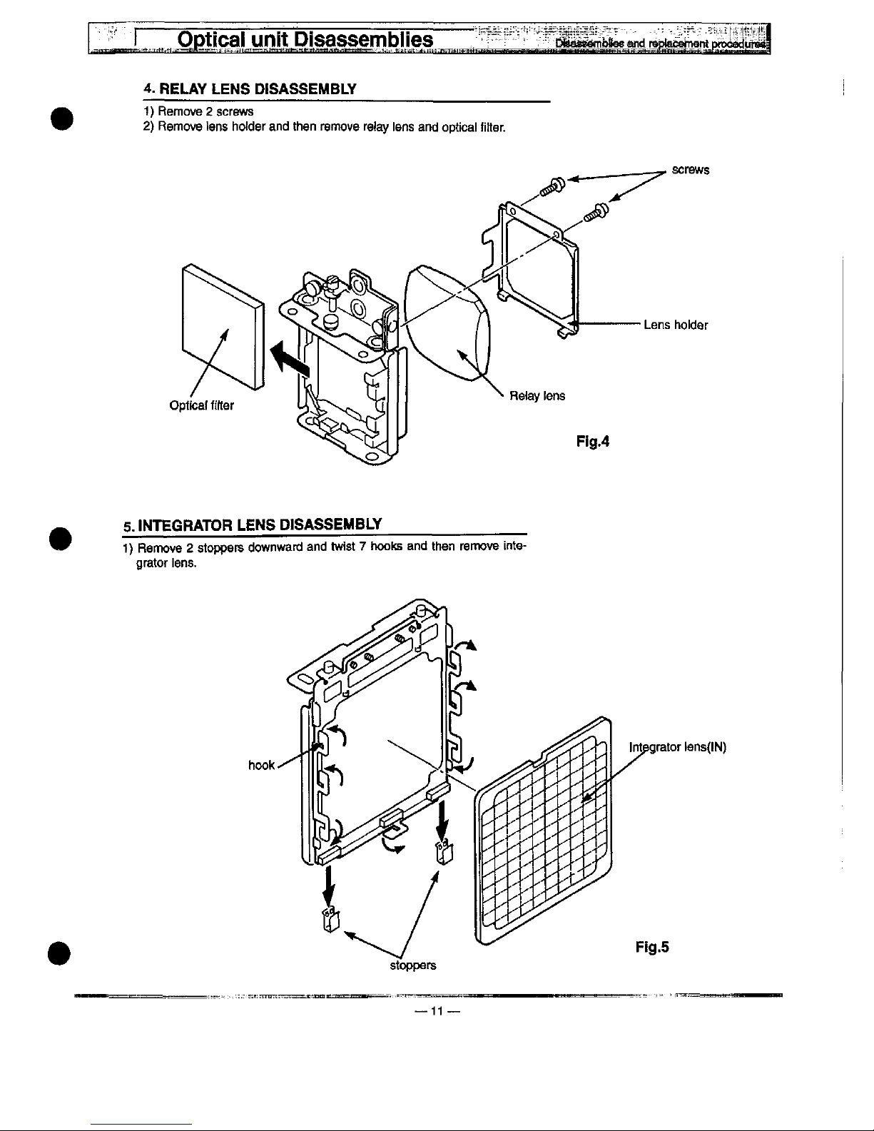
4.
RELAY
LENS
DISASSEMBLY
1)
Remove 2 screws
2)
Remove
tens
hofder
and
then
remove
retay
tens
and
optica)
fitter.
screws
Lens
hohjer
5.
tNTEGRATOR
LENS
D)SASSEMBLY
1)
Remove 2 stoppers
downward
and
twist 7 hooks
and
then
remove
inte-
grator
iens.
hook
Integrator
(ens(!N)
Fig.5
stoppers
11

6.
OPTICAL
BASE
TOP
REMOVAL
Remove 9 screws
and
then
puf)
the
optica)
baae
top
upwafd.
Optical
base
top
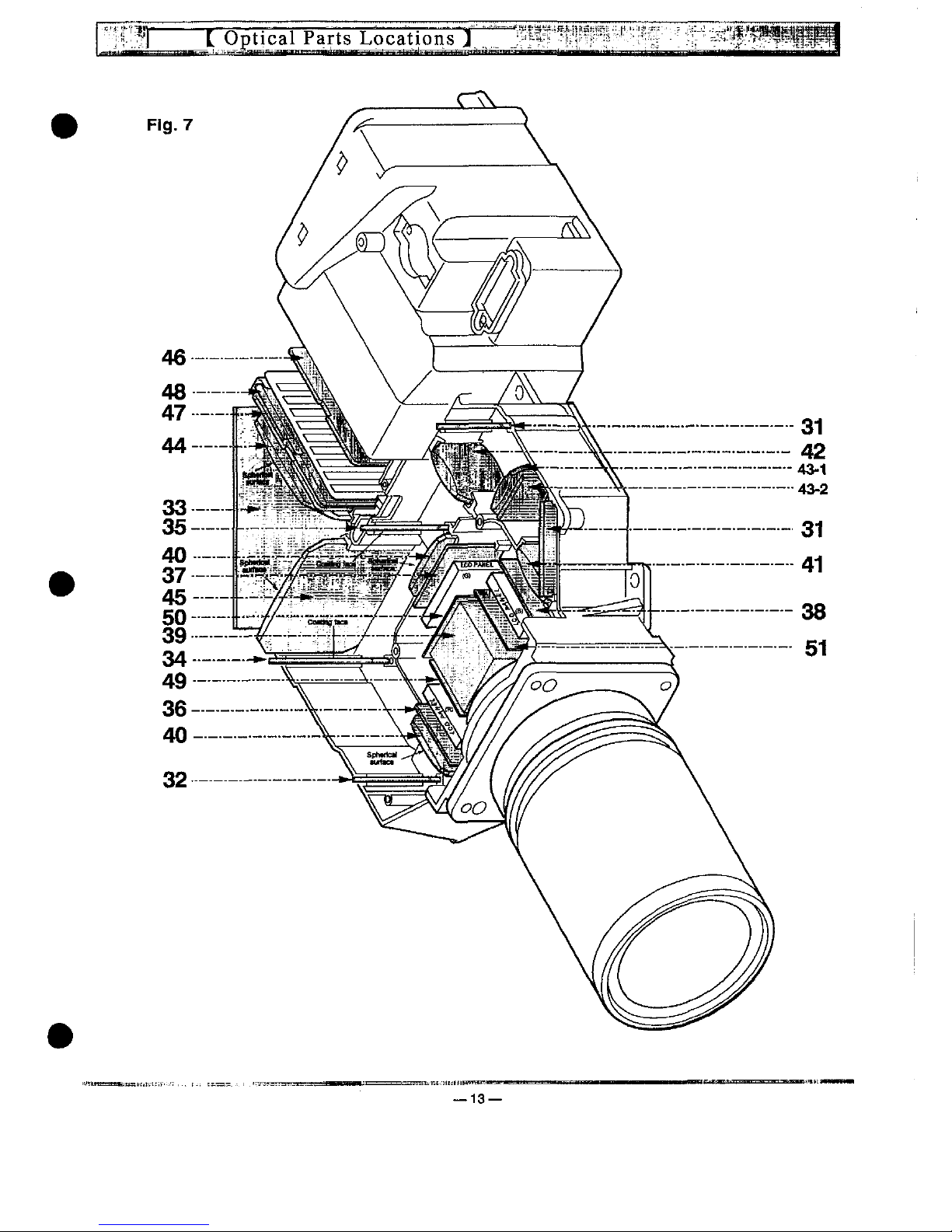
OPTICAL
31
32
33
34
35
36
37
38
39
40
41
PARTS
LOCATES
MIRROR(B)
MIRROR(R)
MIRROR(W)
DICHROIC
MIRROR
(R)
DICHROIC
MIRROR
(G)
POLARIZED
GLASS-IN(R)
POLARIZED
GLASS-IN(G)
POLARIZED
GLASS-IN(B)
ASSY,PRISM
LENS,
COmSER
LENS.CONDENSER(B)
Refer
to
.next
page
42
LENS.RELAY(IN)
43-1
LENS.RELAY(OUT)
43-2
OPTICAL
FILTER(UV
CUT)
44
LENS.CONDENSER(IN)
45
LENS,
CONDE^ER(OUT)
46
LENS.
ItTTEGRATORdN)
47
ASSY.LENS,INT.(OUT)
48
PRISM(P.B.S.)
(Polarized
Beam
Splitter)
49
POLARIZED
GLASS-OUT(R)
50
POLARIZED
GLASS-OUT(G)
51
POLARIZED
GLASS-0[fT(B)
NOTE;
Key
MO.
49,
50
and
SKpotartxed-glass-out
R,
G
and
B)
are
not
used
in
some
particular
models.
12—
-13—
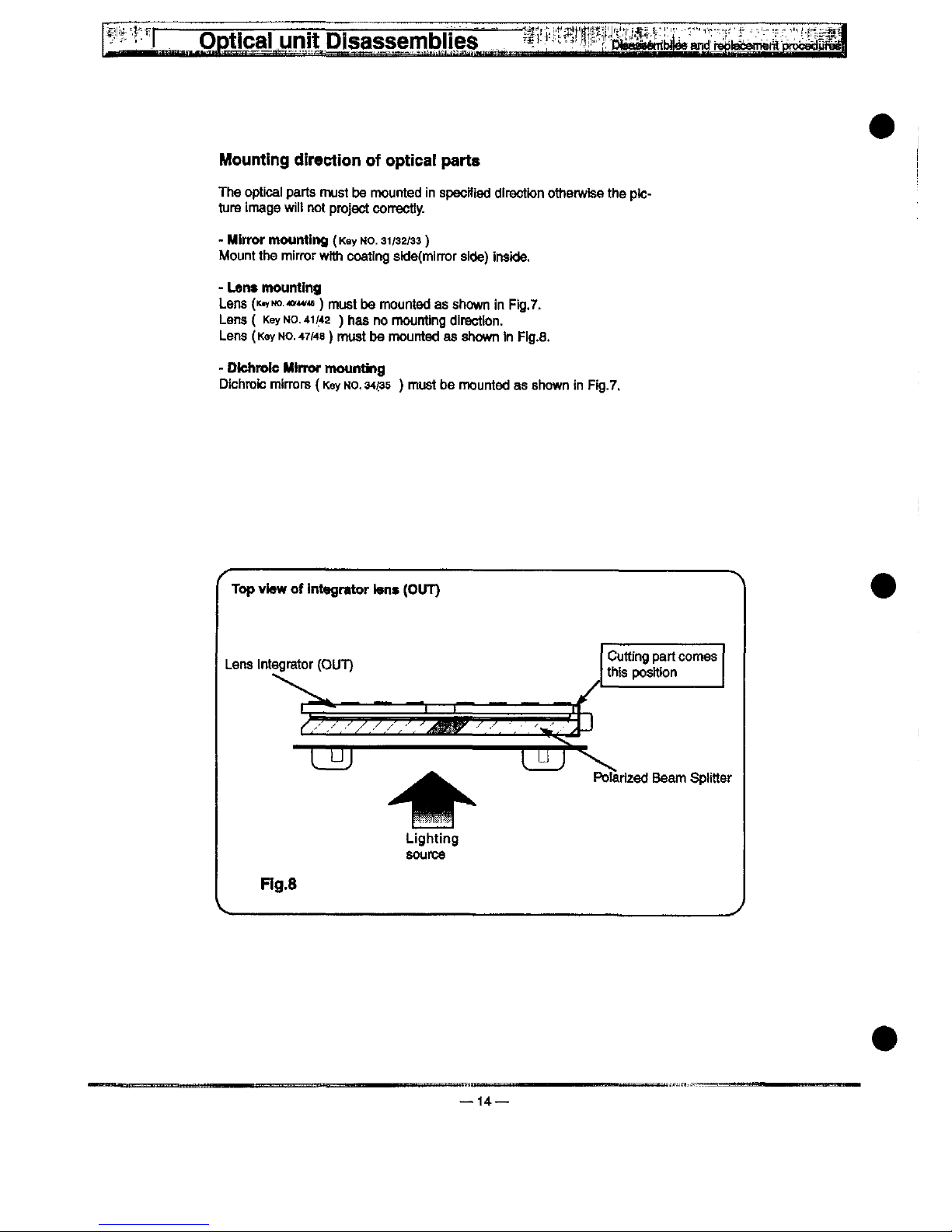
Mounting
direction
of
optica!
parts
The
optical
parts
must
be
mounted
in
specified
direction
otherwise
the
ptc-
ture
image
wiit
not
project
correctiy.
-
Mirror
mounting
(Key
Mo.
31/32/33)
Mount
the
mirror
wHh
coatfng
sidefmirror
side)
inside.
-
Lent
mounttng
Lens
(K^Mo.<of^<e)
must
be
mounted
as
shown
in
Fig.7.
Lens(
Key
No.
41/42
)hasno
mounting
directton.
Lens
(Key
MO.
47/48)
must
be
mounted
as
shown
tn
FJg.a.
-
Dtchrotc
Mtnw
mounting
Dichroic
mtrrors
(Key
NO.
34/35
)
must
be
mounted
as
shown
in
Fig.7.
/^\
Top
view
of
integrator
ten*
(OUT)
Cuttfng
part
comes
this
position
1^—————[^T^
Pofartzect
Beam
Sptitter
Lighting
source
Fig.8
14

!!.^.!'F^
'.,.
'E^^^-^^J^^
^-:{.V^D&^
f.
Remove
the
FPC
cabfe
on
the
main
board.
2.
Remove 4 screws
(A=B)ue,
B=Green,
C=Red)
for
the
assy
LCD
Pane).
3.
Pu)!
out
the
ass'y
LCD
Pane).
Remove 3 screws,
^en
remove
the
LCD
Pane)
and
replace
it.
LCD
pane!
mounting
ptate
Green
Panet
unit
—15
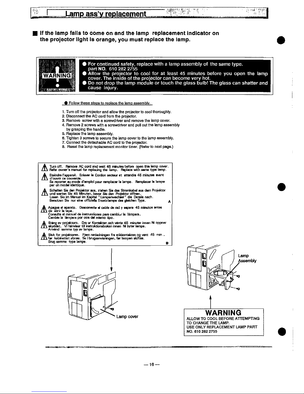
tf
the
tamp
fai!s
to
come
on
and
the
tamp
replacement
indicator
on
the
projector
!ight
is
orange,
you
must
replace
the
!amp.
^
For
continued
safety,
replace
with a lamp
assembly
of
the
same
type.
part
NO.
6102822755
^
AHow
the
projector
to
coo)
for
at
teast
45
minutes
before
you
open
the
tamp
cover.
The
inside
of
the
projector
can
become
very
hot.
^
Do
not
drop
the
iamp
modu!e
or
touch
the
glass
buib!
The
giass
can
shatter
and
cause
injury.
^FoUQW
those
steps
to
replace
the
tamp
assembly.
1.
Turn
off
the
projector
and
a))ow
the
projector
to
coo)
thoroughfy.
2.
Disconnect
the
AC
cord
from
the
projector.
3.
Remove
screw
with a screwdriver
and
remove
the
tamp
cover.
4.
Remove 2 screws
with a screwdriver
and
putt
out
the
tamp
assembfy
by
grasping
the
handle.
5.
Replace
the
[amp
assambty.
6.
Tighten 3 screws
to
secure
the
tamp
cover
to
the
tamp
assembty.
7.
Connect
the
detachabte
AC
cord
to
the
projector.
8.
Reset
the
[amp
replacement
monitor
timer.
(Refer
to
next
page.)
Turn
off.
Remove
AC
cord
and
wait
46
mitKftes
bofofe
open
this
tamp
cover.
Refer
owner'?
manuat
for
reptacing
the
tamp-
Reptace
whh
same
type
tamp.
Eteindre
f'apparait.
Entever
)a
Cordon
aectauf
et
attendra
46
minutes
avant
d'owrir
ce
couvercte.
Se
ntportar
au
mode
d'empfoi
pour
remp!acer
t<
tampe.
RetDpbcar
fa
tampe
par
un
mode)
ktentique.
Schatten
Sie
den
Projektor
aus.
z!ehen
Sia
dss
Stromkabet
aus
dam
Projektor
und
warten
Sie
45
Mnuten.
bevor
Sie
den
Pn3}ektof
offnen.
LeMn
Sie
im
Manua)
im
Kapite! ' LampenwechM)"
die
Dataits
nacfi.
Benutzen
Sie
nur
cine
offiziette
Ersatz
!ampe
dM
gfeichon
Typt.
^
Apagua
e)
aparato.
Desconocte
a)
cabte
da
rad y aapera
45
minutoe
antes
t
de
abrir
ta
tapa.
Consuho
o!
manuat
de
instnjccionss
para
cambiof
ta
tampafa.
Cambte
ta
!ampam
per
otra
de)
mismo
t^M.
Stang
sv
projektom.
Dra
ur
Kontattteti
och
vanta
46
neuter
innan
Ni
oppnar
^skydoet.
VtharMsartititnstruk^onsbotcBninnan
MbylBrtampa.
Anvand
aamma
typ
av
tampa.
Sk'ttforpfojetctorBn.
^jemnettedningenfras^hkontaktenogvent
45
rnif)..
tfar
kabinettetabnes-
Seibnjgsanvisningen.ferfampenshiftM.
Brug
samme
type
tampe.
n
Lamp
cover
Lamp
AssemMy
WARNtNG
ALLOW
TO
COOL
BEFORE
ATTEMPTtNG
TO
CHANGE
THE
LAMP.
USE
ONLY
REPLACEMENT
LAMP
PART
N0.6102822755
16
Lamp
ass'yMplacement
^
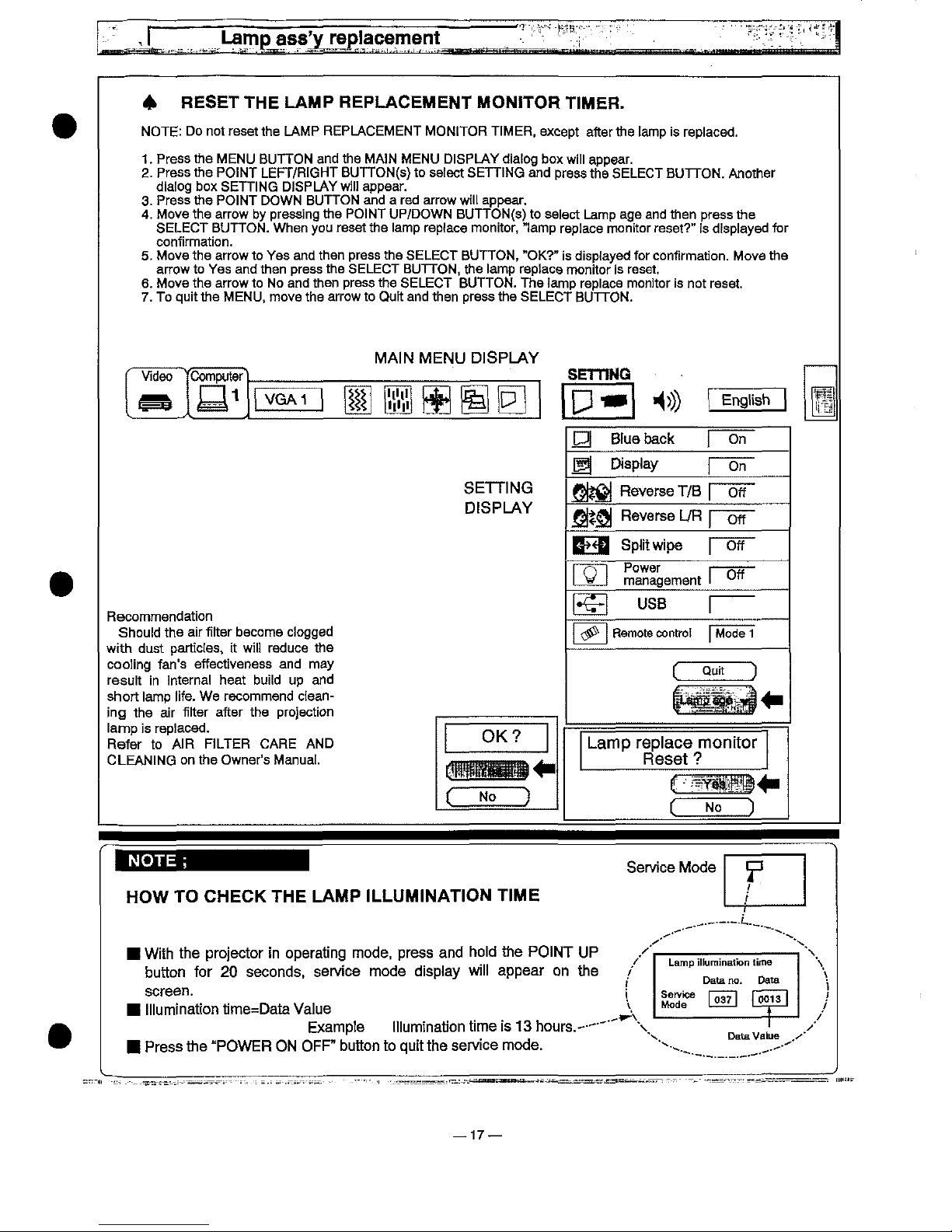
RESET
THE
LAMP
REPLACEMENT
MON!TOR
T)MER.
NOTE:
Do
not
reset
the
LAMP
REPLACEMENT
MONtTOR
TtMER,
except
after
the
[amp
is
rep)aced.
1.
Press
the
MENU
BUTTON
and
the
MA)N
MENU
D)SPLAY
diabg
box
wiii
appear.
2.
Press
the
POiNT
LEFT/RtGHT
BUTTON(s)
to
seiect
SETTiNG
and
press
the
SELECT
BUTTON.
Another
diafog
box
SETDNG
DJSPLAYwiii
appear.
3.
Press
the
POiNT
DOWN
BUTTON
and a red
arrow
wiii
appear.
4.
Move
the
arrow
by
pressing
the
PO)NT
UP/DOWN
BUTTON(s)
to
se)ect
Lamp
age
and
then
press
the
SELECT
BUTTON.
When
you
reset
the
tamp
repface
monitor,
"tamp
repiace
monitor
reset?"
is
displayed
for
confirmation.
5.
Move
the
arrow
to
Yes
and
then
press
the
SELECT
BUTTON,
"OK?"
is
disptayed
for
confirmation.
Move
the
arrow
to
Yes
and
then
press
the
SELECT
BUTTON,
the
iamp
roptace
monitor
is
reset.
6.
Move
the
arrow
to
No
and
then
press
the
SELECT
BUTTON.
The
famp
replace
monitor
is
not
reset.
7.
To
quit
the
MENU,
move
the
arrow
to
Quit
and
then
press
the
SELECT
BUTTON.
MAIN
MENU
DISPLAY
't't'
'!')'
Engtish
Btue
back
Disptay
SETDNG
DfSPLAY
Reverse
T/B
Reverse
L/R
B^<B
Sp)itwipe
Power
management
Recommendation
Should
the
air
fitter
become
ciogged
with
dust
partlctes,
[t
wiH
reduce
the
cooling
fan's
effectiveness
and
may
resuit
in
internal
heat
buiid
up
and
short
iamp
iife.
We
recommend
clean-
ing
the
air
fitter
after
the
projection
tamp
is
reptaced.
Refer
to
AIR
FtLTER
CARE
AND
CLEANING
on
the
Owner's
Manual.
US8
Remote
controi
Mode
1
Quit
Lamp
rep)ace
monitor
Reset
?
No
NOTE
;
HOW
TO
CHECK
THE
LAMP
)LLUM)NAT)ON
T)ME
F
/
With
the
projector
in
operating
mode,
press
and
hotd
the
PO!NT
UP
button
tor
20
seconds,
service
mode
disptay
witt
appear
on
the
screen.
tttumination
time=Data
Vaiue
Exampte
titumination
time
is
13
hours.'--"
Press
the
"POWER
ON
OFF"
button
to
quit
the
service
mode.
Lamp
iHumination
time
Data
no.
Data
',
^^
[1^
f^]
A
!————————}—
Data
Va!ue
.^'
—17
SAFETY
tNSTRUCTtONS
r
SAFETY
PRECAUT^ONS^
WARNING:
The
chassis
of
this
projector
is
isolated
(COLD)
from
AC
fine
by
using
the
converter
transformer.
Pr)mary
s!de
of
the
converter
transformer
and
tamp
power
suppty
unit
circuit
is
connected
to
the
AC
line
and
tt
ia
hot,
which
hot
circuit
is
identified
with
the
iino
in
the
schematic
diagram.
For
continued
product
safety
and
protection
of
personnet
injury,
servicing
should
be
made
wtth
quali-
fied
personnel.
The
following
precautions
must
be
observed:
1.
An
isolation
transformer
shouid
be
connected
in
the
power
iine
between
the
projector
and
the
AC
itne
before
any
service
is
performed
on
the
projector.
2.Comp)y
with
aii
caution
and
safety-
related
notes
provided
on
the
cabinet
back,
cabinet
bottom,
inside
the
cabinet
or
on
the
chassis.
3-
When
reptadng a chassis
in
the
cabinet,
aiways
be
certain
that
atf
the
protective
devices
are
instated
property,
such
as
control
knobs,
adjustment
covers
of
sh!e)ds
and
barriers.
DO
MOT
OPERATE
THIS
PROJECTOR
W!TH-
OUT
THE
PROTECTIVE
SHIELD
iM
POSmON
AMD
PROPERLY
SECURED.
4.
Before
repfacing
the
cabinet
cover,
thorough!/
inspect
the
insfde
of
the
cabinet
to
see
that
no
stray
parts
or
too)s
have
been
left
inside.
Before
returning
any
projector
to
the
customer,
the
service
personnel
must
perform
the
following
safety
checks
and
be
sure
that
it
is
compieteiy
safe
to
operate
without
danger
of
electrical
shock.
r
PRODUCT
SAFETY
NOTiCE
]
Product
safety
shouid
be
considered
when a component
repfacement
is
made
in
any
area
of
the
projector.
Components
indicated
by a mark
(^)
in
the
parts
iist
and
the
schematic
diagram
designate
components
in
which
safety
can
be
of
special
significance,
it
is,
therefore,
particularly
recommended
that
the
reptace-
ment
of
these
parts
must
be
made
by
exactly
the
same
parts.
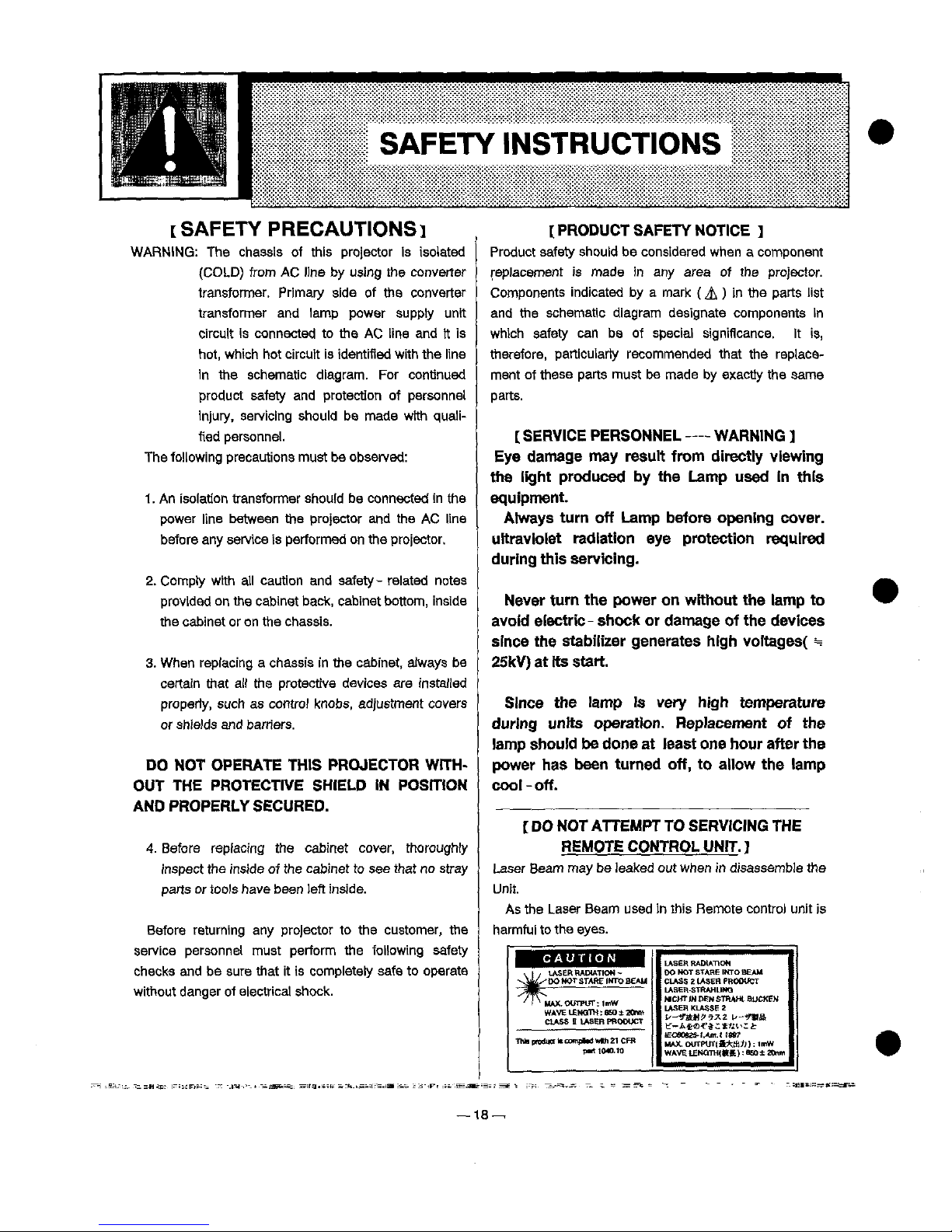
^
SERVICE
PERSONNEL
WARNING
j
Eye
damage
may
result
from
directiy
viewing
the
fight
produced
by
the
Lamp
used
tn
this
equipment.
Atways
turn
off
Lamp
before
opening
cover.
uttravioiet
radiation
eye
protection
required
during
this
servicing.
Never
turn
the
power
on
without
the
tamp
to
avoid
efectric-
shoctt
or
damage
of
the
devices
since
the
stabilizer
generates
high
voitages(
=
25kV)
at
its
start.
Since
the
!amp
is
very
high
temperature
during
units
operation.
Replacement
of
the
tamp
shouid
be
done
at
least
one
hour
after
the
power
has
been
turned
off,
to
aiiow
the
iamp
cooi - off.
(
DO
NOT
ATTEMPT
TO
SERVING
THE
REMOTE
CONTROL
UNIT.
^
Laser
Beam
may
be
leaked
out
when
in
disassemble
the
Unit.
As
the
Laser
Beam
used
in
this
Remote
control
unit
is
harmful
to
the
eyes.
t
CAUTfON
^
^ j ,
LASER
RADU.DOW-
^^^
DO
MOT
STARE
!MTO
BEAU
^^MAX.tXfnvr;)mW
WAVE
^EWaTW:
eso ± ZOnm
f^ASS
!t
U^SM
PRODUCT
TM<pnMmN"co^)tMw)th2t
CFR
p^HMO-M
00
HOT
STARE
'MTO
SEAM
CLASS 2 tASEH
PROOUCT
LASER
STRAHUHQ
MCM'
tM
DEW
STRA^t-
BUCKEM
LASER
KLASSE:
^--f&HP-^Z
^-'^Ba
tr-Ata^^.:t^^^t
tEC6092S-t^m.t
tat7
MAX.OUTP'jrj&^tf^):'"W
WAVELEMOrm<t^):aso±20Mn
18
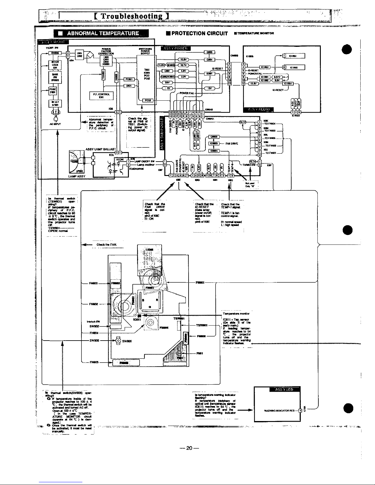
This
projector
is
equipped
with
the
foitowing
circuit
protections
to
operate
in
safety.
if
the
abnormaifty
occurs
inside
the
projector,
it
wii!
automatically
turn
off
by
operating
one
of
the
foHowing
protection
circuits.
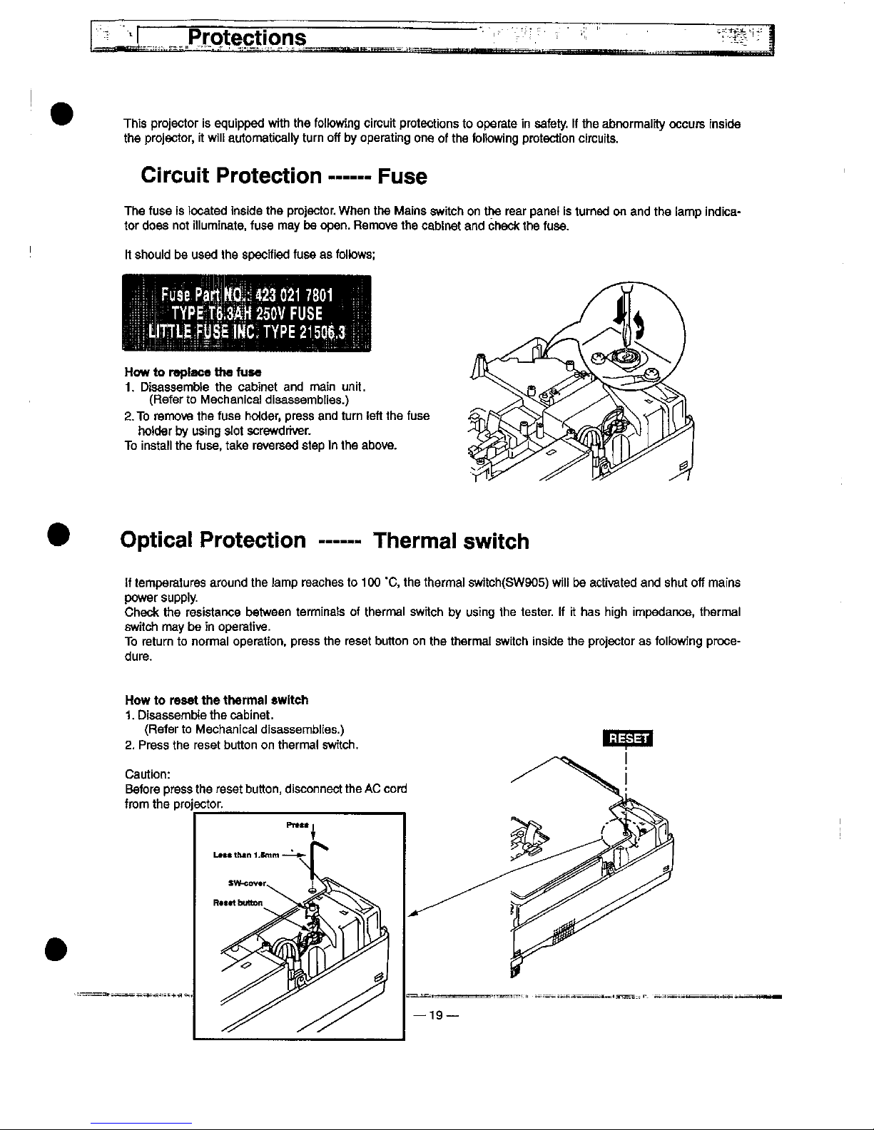
Circuit
Protection
Fuse
The
fuse
is
located
inside
the
projector.
When
the
Mains
switch
on
the
rear
panef
is
turned
on
and
the
tamp
indica-
tor
does
not
itiuminate.
fuse
may
be
open.
Remove
the
cabinet
and
check
the
fuse.
tt
shouid
bo
used
the
specified
fuse
as
foitows:
FuaePa'tt^^230217801
TYPE
T$:3AH
250V
FUSE
How
to
reptace
the
fuae
1.
Disassembte
the
cabinet
and
main
unit.
(Refer
to
Mechanica!
disassemblies.)
2.
To
remove
the
fuse
ho<der,
press
and
turn
feft
the
fuse
hotder
by
using
stot
screwdriver.
To
instati
the
fuse,
take
reversed
step
in
the
above.
Optical
Protection
Therma!
switch
!f
temperatures
around
the
famp
reaches
to
100
'C,
the
thermat
switch(SW905)
w!it
be
activated
and
shut
off
mains
power
supp)y.
Check
the
resistartce
between
terminats
of
therma!
switch
by
using
the
tester,
tf
it
has
high
impedance,
thermal
switch
may
be
in
operative.
To
return
to
normai
operation,
press
the
reset
button
on
the
thermal
switch
inside
the
projector
as
foifowing
proce-
dure-
How
to
reset
the
therma)
twitch
1.
Disassembte
the
cabinet.
(Refer
to
Mechanfcai
disassemblies.)
2.
Press
the
reset
button
on
therma)
switch.
Caution:
Before
press
the
reset
button,
disconnect
the
AC
cord
from
the
projector.
tt
One*
tt*
thtnntt
tt^ch
wB
et^fN^ttd.
tmutt
&t
ftttt
21—

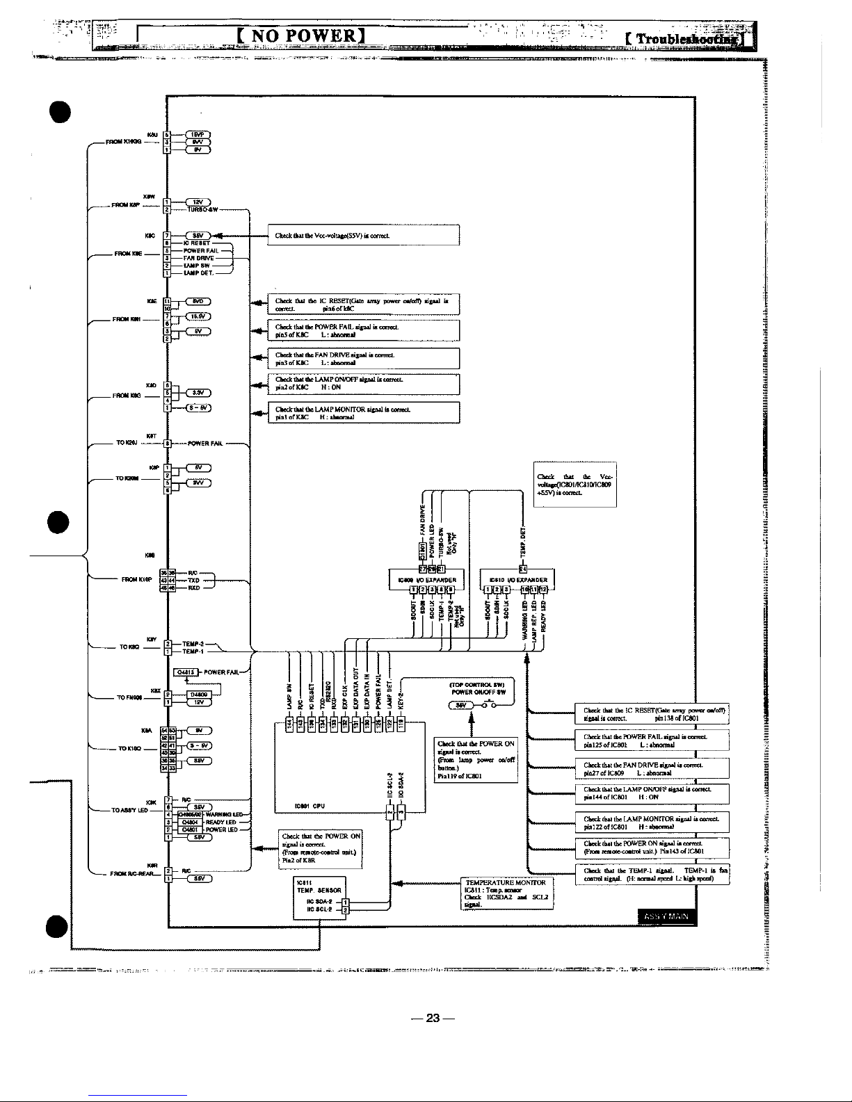
C
NO
POWERS
--23—
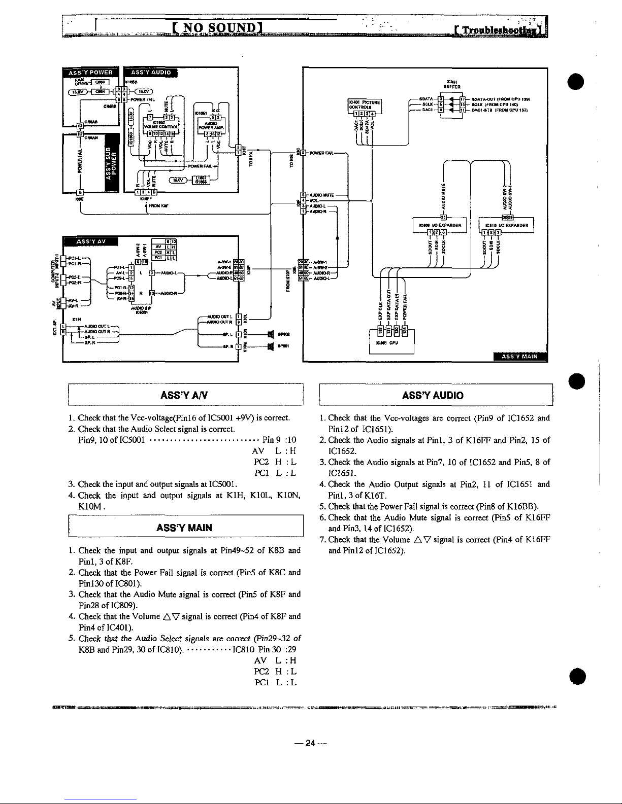
ASS'YA/V
ASS'YAUD)0
1.
Check
that
the
Vcc-voItage(Pinl6
of
IC5001
+9V)
is
correct.
2.
Check
that
the
Audio
Setect
signal
is
correct.
Pin9,10ofIC5001
.....................----..p;n9
:10
AV L :H
PC2 H :L
PC1 L ;
L
3.
Check
the
input
and
output
signals
at
IC5001.
4.
Check
the
input
and
output
signals
at
K1H,
K10L,
K10N,
K10M.
ASS'YMA)N
1 - Check
the
input
and
output
signals
at
Pin49-52
of
K8B
and
Pinl.3ofK.8F.
2-
Check
that
the
Power
Fait
signal
is
correct
(Pin5
of
K8C
and
Pinl30ofIC80I).
3.
Check
that
the
Audio
Mute
signal
is
correct
(Pin5
of
K8F
and
Pin28ofIC809).
4.
Check
that
the
Vo)ume
AV
signa!
is
correct
(Pin4
of
K8F
and
Pin4of!C401).
5.
Check
that
the
Audio
Select
signats
afc
correct
(Pin29-32
of
K8B
and
Pin29,
30
of
IC8IO).
...........
IC8IO
Pin
30
:29
AV L :H
PC2 H :L
PC1 L :L
1.
Check
that
the
Vcc-voltages
are
correct
(Pin9
of
IC1652
and
P:nl2of
IC1651).
2-
Check
the
Audio
signals
at
Pint, 3 of
K16FF
and
Pin2,
15
of
IC1652.
3-
Check
the
Audio
signals
at
Pin7,
10
of
IC1652
and
Pin5, 8 of
JC165J.
4.
Check
the
Audio
Output
signals
at
Pin2,
11
of
tC1651
and
Pml,3ofK16T.
5.
Check
that
the
Power
Fait
signa!
is
cornet
(Pm8
of
K16BB).
6.
Check
that
the
Audio
Mute
signa!
is
correct
(Pin5
of
K16FF
and
Pin3.14
of
IC1652).
7.
Check
that
the
Vohme
AV
signal
is
correct
(Pin4
of
K16FF
and
Pinl2
of
IC1652).
—24
 Loading...