

Sanyo PLC-XP21N, PLC-XP21E, PLC-XP21B Service Manual

SERV)CE
MANUAL
Mutti-media
Projector
S4^0
F/L^
NO.
MODEL
NO.
PLC-XP21
N
(U.5.A.
,Canada)
PLC-XP21
E
(Europe,
Asia,
Africa,
M.E.)
PLC-XP21
B
(U.K.)
ORiGtNALVERSiON
Chassis
No.
MF6-XP21NOO
PLC-XP21
EOO
PLC-XP21BOO
NOTE:Match
the
Chassis
No.
on
the
unit's
back
cover
with
the
Chassis
No.
in
the
Service
Manuai.
if
the
Ortginai
Version
Service
Manua)
Chassis
No.
does
not
match
the
unit's,
additiona)
Service
Literature
is
required.
You
must
refer
to
"Notices"
to
the
Origina)
Service
Manuat
prior
to
servicing
the
unit.
Give
complete
"Chassis
NO."
for
parts
order
or
servicing,
[t
is
shown
on
the
rating
sheet
on
the
cabinet
of
the
Projector.
CC
Specifications
....--------
Disassemblies
and
Replacemen
Mechanical
disassemblies
Optical
unit
disassemblies
LCD
pane)
replacement
-
Assy
lamp
replacement
-'
Safety
Instructions
---------
Circuit
Protections
.....----
Troubleshooting
......-.-.
Waveforms
..------"--"
Alignment
Procedures
------
Service
adjustments - -
- - -
Focus
adjustments - -
" "
Convergence
adjustment
Product
Code
: 1 122
073
60
: 1 12207460
: 1 122
074
62
INTENTS
..............................
^
tt
Procedures
.-------......
3-17
...........................
9^14
.............................
15
.............................
19
..........................
20-27
..........................
38-39
.............................
^0
PLC-XP21N
MF6AF
PLC-XP21E
PF6AF
PLC-XP21B
PF6CF
Integrator
lens
adjustment
.......................
Polarized
glass
adjustment
.---.---.....----..---
CPU
input/output
port
functions
.---..--.---.-.------
Maintenance......................................
Notes
on
schematic
diagram
..-.-.--------...-------
Cabinet,
Chassis
and
Optical
parts
list
--....-..----.
Parts
location
and
PWB
pattern
diagrams
.----..-.....
Block
diagram
and
Low
power
distribution
---......-..
Schematic
diagrams
.-.--.--...--..-------..---..-
REFERENCE
NO.
......
41
------
42
------
43
- - - 44-47
..-
48-49
- - - 50-51
- - - 52-79
- - -
54"-58
- - -
59-79
SM5110202
PLC-XP21N
PLC-XP21E
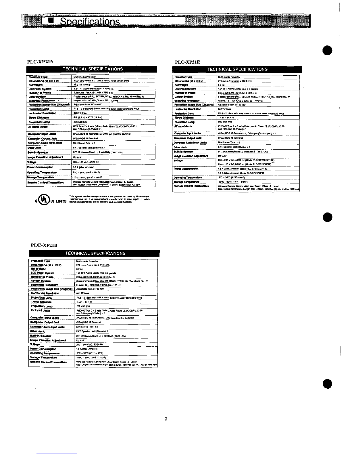
TECHN)CAL
SPEOFiCATfONS
TECHN)CAL
SPEOFJCATtONS
pr^tctofTn^
Dtt)«n*tent(W!fHtD)
tMWtfoM
LCO^«ty*tM!'
Mmnt^«Pt]t'tt
Ce)et<^**M
ac<mtr)Q
rrxrn""^
fMtMttonitf*a*atzt[Dtte''"'')
^^^U^!
HoftmnMtttt^BMton
Ttx^wOM-ne*
fM^tettent^mp
^ttttUt^M**
c<w<)pmtrtt^mj«t*
CetxpMttf
Output-fct
Cmmptt*r*Hdh'f^<HJ*attt
Othtr^ett
MtHtap-'tfMf
)-MWBM*Men*t<n«ttMnt
^Mt*o*
P<^rC<^Mmp<KM
Op<MHM()Tt«)p<ntt)tt<
attt^*T*<nptm<tUt<
ft^.C^^T^^-.
MMM-mtdH
P^'ctc'
10.7-
(272mm)
.6.7-
f)4S.Smm),
K.2-
(tt2 5 mmt
t6.:!bt<6.eta)
1.3'TFrAMvtMMtt'^p*
'3f-n^*
M6t,Me
!7M.o:
f'.m< ' Tet) t a)
e
M)e.
^.Mm
(P*L.
MCAM.
tT^c.
MTMM.O.
ML-M
tmt
^L-N)
H-^ne.tS-)MKm.VtYM.M.)0))Ht
*qtitH<!tt'r<m3I''o4M'
FI.<-2TtntwW!t-«.<nm-^.tmmMm.tcam^d'o!M
MtTVXntt
4.t'<].4m)-<7.J<14.4m)
MOwMttp.
^D^4^^^'^""^"^''^'^'^'
(WA)HMtST.nnMJ.2.D)Nt^<C<nM)ponf2
(WMtt^ettT^minti
M^St^el^.j.2
EXT.8pt*ttfJtti((3t*ftO)''
^MT.3P6)n*e<H*^L).!wMHUsjT.H.CHO^)
UpMt'
'M^MVAC.KWHz
3.eA(M^.A^^
6'C'3e'Cf4''F-t6'F)
-IO-c-M-Cn4'F-14<fF)
M*<Ouaiut"^M^.L*n^hMftt:om.6t<ttnttf!)**Wt.
PmftctctTtp*
DfM^MtfWxHKO]
HOW't^t
).eOP*M<)'yfm
MmnXwrofPOf^t
CC'e')rS^*)M
acxnntnct^qu^e^
PtCt*e''ottttHtjttSht(Dt))jn)n.t<)
Hot^MiM<B«eMton
f^ttt)'onf-*n*
Tt^wDM*net
PMf<eNcnt.Mtp
^V)f)ttt<J«af
eeMpm*r)nt<m*M'm
Ceotpo^OutMtJ'cft
Cefnt)UMfJhtdfo'Hpu)J^)tt
tMtMfJ'Mt
Boemttp't'r
)m<(tt&m«tMtMtU^MM
^<M(X
fe^Contumpttcn
Opm(tne-r*mptn<m*
)ttM(t*Tt«)<xn)tUM
tt^t.C^^Tt—nOt^
Muttt-mtanPrc^Ma.
272
mm . 145.5
mm , 4^.6
mm
ett^
t^'TFrAf^tMtmttypt
t3ptn^t
2,3fe.Mt
(TM.'M
(t
.M41
TM) < 3}
6
tKo^'
t^ttm
fP*L
SECAM.
NTSC.
MTSC4.43.
Mj..M
*na
fW.-N)
H-^n:.
'6 - )<M
«Ht.
^t^nc. K '
'«
H!
*^UtfU''mm3I'<o40t)-
MOTVhn..
F^.< - 2.'
ttnt^f
t^.4
mn. - M.Bmm
Mo<ot
mtrntrdtom^
t.<m-t4.4m
M(!-M<M)t
^^^^^^'^'"^"'^'^°'^
{VGA)
HDB
^Ttmitntt
12.
CMN < pm
tCa*d
pat) ^ 2
(VO*)HM^T.mt^
M^SM^TYp*);!
E)tT.!.p^^J-^t8t.^o)JH
^.SP.S'M.!RML).:-*ttRMar^D.IO%)
UpMt'
!00 - MO^
AC.
MMO
Ht
(MeCf
PLC-XP2'&XPHE)
"0-
1MV*C.
M^O
Hi
(Modf
PLC-)tP2"XPIt)
'^AfMt.*mp*'*)Me<MPLC-XM'E/Xf<E
3.6*[UM.*mp^.)MnMPLC.XM1MPH
M - 3FC
{41-^ - M-F)
-1f^C-M°C('<'F-t^M
^S^^^^L^^^m^^^.^^
PLC-XP21B
TECHNfCAL
SPECfPfCATfONS
Pto)*ctor-rvpt
Nm*tMion<[WxH]tD]
M*tWtt))ht
[.CD^MftYtttm
M^^^^^
e<t^)f<Mt*m
BatnntnaPttqmncy
PK')M<Mttt)n)()*atz*fD<t<)OM<)
Haf'iMnt'ttRtteMten
PrefeNonLtn*
Th'<^Cttt)M)Ct
PMf^t^Dmp
AV)npt)t4^t
CM<^tfMf)f^utJ<tCKt
C<Mnpm<rO^<<pt)(J)te):
CBmpt<t*fAtKttotn^^ekt
Oth^Joet!
MMnNt)^^
'M)^*Ef<M''tanAdtu*tnMnt
W)<^^*
'^MfCofMtmtp)ton
Op*n<tn(tTtmp*rttuf<
Mof*B'TM)ptr*h^t
'^^M*
ControtTfttto^tM*
Mttt-m^t.
P^^to.
:7Smm.nS.Smmt412.5m^
e.ft)
t^'TFrAM^MMm:^pt
'3p^^t
2.3M.2ee
(TM.4M
ft.OM
176t)
13)
e
tBtou'
ty«tm
{PM..
SEC*M.
m-sc.
MTSC4.43.
R^-.M
tnd
PM.-^
H-^nc.^-IOOMhz.^-^no.So-tMH!
At<utttt))t'mm3''tn400-
MOTV^.t
FI.t-:.t)tHt
wMX-M.4mm.-M.emn.
Motif
mm
tnd
bout
1.4m-'4.4m
^WtttfHX
^^^^^"'^^'''^'^'''^"
(VGA)
HDB
UTtnn^ . S.
D!H 6 pjn
(CcM^
po^) X :
(vaA)HDeiSTtmm^
M^S'^.T^p..2
EXTSptt)tfJttk!SMtO)x'
jNT.SRS<Mtt!(RtnaL!.2**t"tUS{THmO%)
Lfptoa'
2M-240VM.M^OHr
1.6A(U^.Amptft)
:-C-3S-C(4T'F-M'F)
-'0-C-M°C(H-F-140'F.
^^.*^^'L^^
^^^..^^
U^ . ^
W.
Mechanical
disassemble
shoufd
be
made
following
procedures
in
numerica!
order.
Fottowing
steps
show
the
basic
procedures,
therefore
unnecessary
step
may
be
ignored.
Caution:
The
parts
and
screws
shoutd
be
placed
exactly
the
same
position
as
the
origina)
otherwise
it
may
cause
toss
of
per-
formance
and
product
safety.
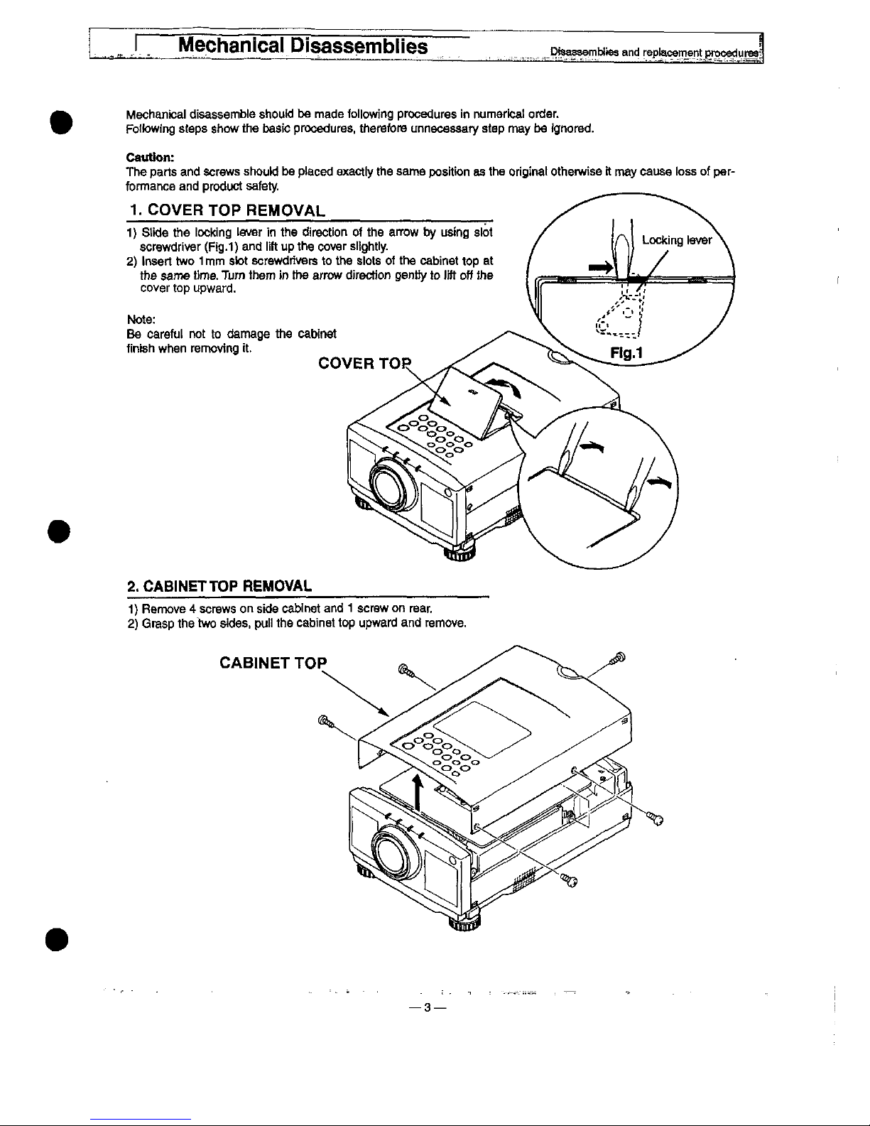
1.
COVER
TOP
REMOVAL
1)
Sttde
the
locking
iever
in
the
direction
of
the
arrow
by
using
slot
screwdriver
(Fig.1)
and
iift
up
the
cover
sitghtiy.
2)
hsert
two 1 mm
stot
screwdrivers
to
the
siots
of
the
cabinet
top
at
the
same
t)me.
Turn
them
in
the
arrow
direction
gentty
to
iift
off
the
cover
top
upward.
Note:
Be
carefut
not
to
damage
the
cabinet
finish
when
removing
it.
COVER
TOP
2.
CABtNETTOP
REMOVAL
1)
Remove 4 screws
on
side
cabinet
and 1 screw
on
rear.
2)
Grasp
the
two
sides,
pui!
the
cabinet
top
upward
and
remove.
CABtNET
TOP
—3—
Mechanica)
Disassembles
Disa^embttes
and
reptacemant
pfoceduresj
..tr-r^f-^^
-r_^_^^,-
,-_=)
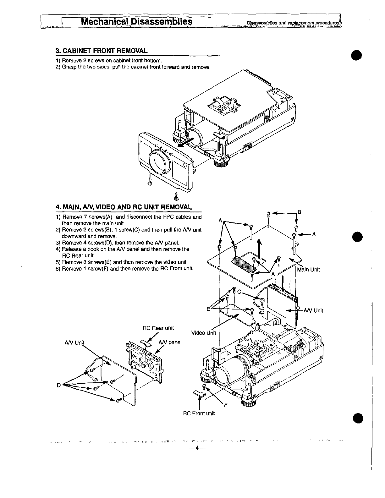
3.
CAB)NET
FRONT
REMOVAL
1)
Remove 2 screws
on
cabinet
tront
bottom.
2)
Grasp
the
two
sides,
put)
the
cabinet
front
forward
and
remove.
RC
Front
unit
—4
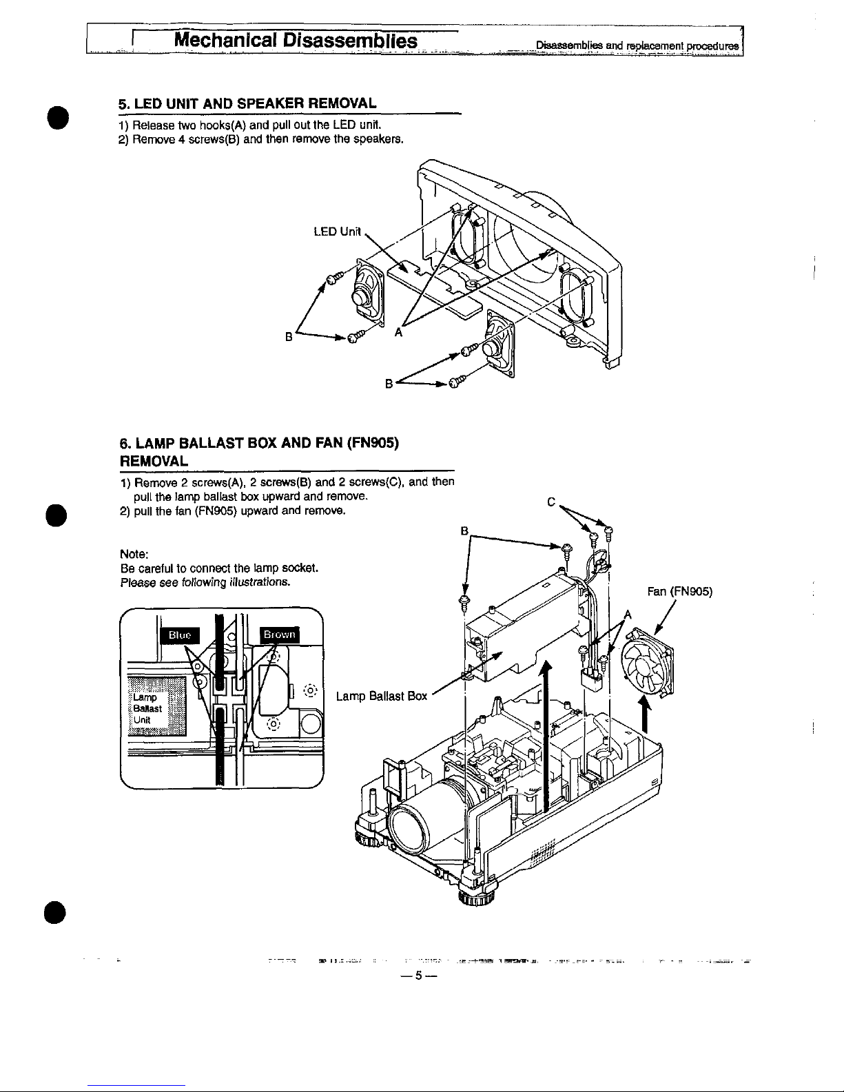
5.
LED
UN!T
AND
SPEAKER
REMOVAL
1)
Retease
two
hooks(A)
and
pu!)
out
the
LED
unH.
2)
Remove 4 screws(B)
and
then
remove
the
speakers.
6.
LAMP
BALLAST
BOX
AND
PAN
(FN905)
REMOVAL
1)
Remove 2 screws(A),
2
screws(B)
and 2 screws(C).
and
then
putt
the
!amp
ba)[ast
box
upward
and
remove.
2)
pu)[
the
fan
(FN905)
upward
and
remove.
Note:
Be
carefut
to
connect
the
tamp
socket.
Ptease
see
fo)towing
frustrations.
—5
Mechanics)
Disassembles
Dtsassembttea
and
reptacement
procedures
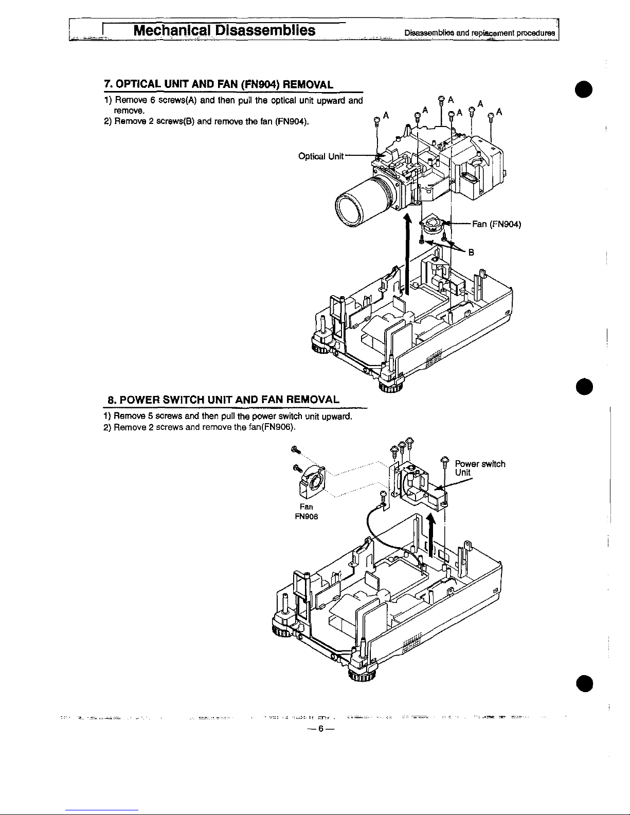
7.
OPTICAL
UNtT
AND
FAN
(FN904)
REMOVAL
1)
Remove 6 screws(A)
and
then
put)
the
optica)
unit
upward
and
remove.
2)
Remove 2 screws(B)
and
remove
the
fan
(FN904).
8.
POWER
SW!TCH
UNiTAND
FAN
REMOVAL
1)
Remove 5 screws
and
then
put)
the
power
switch
unit
upward.
2)
Remove 2 screws
and
remove
the
fan(FN906).
Mechanica)
Disassembles
Dtsaasembties
and
rep)acement
procedures
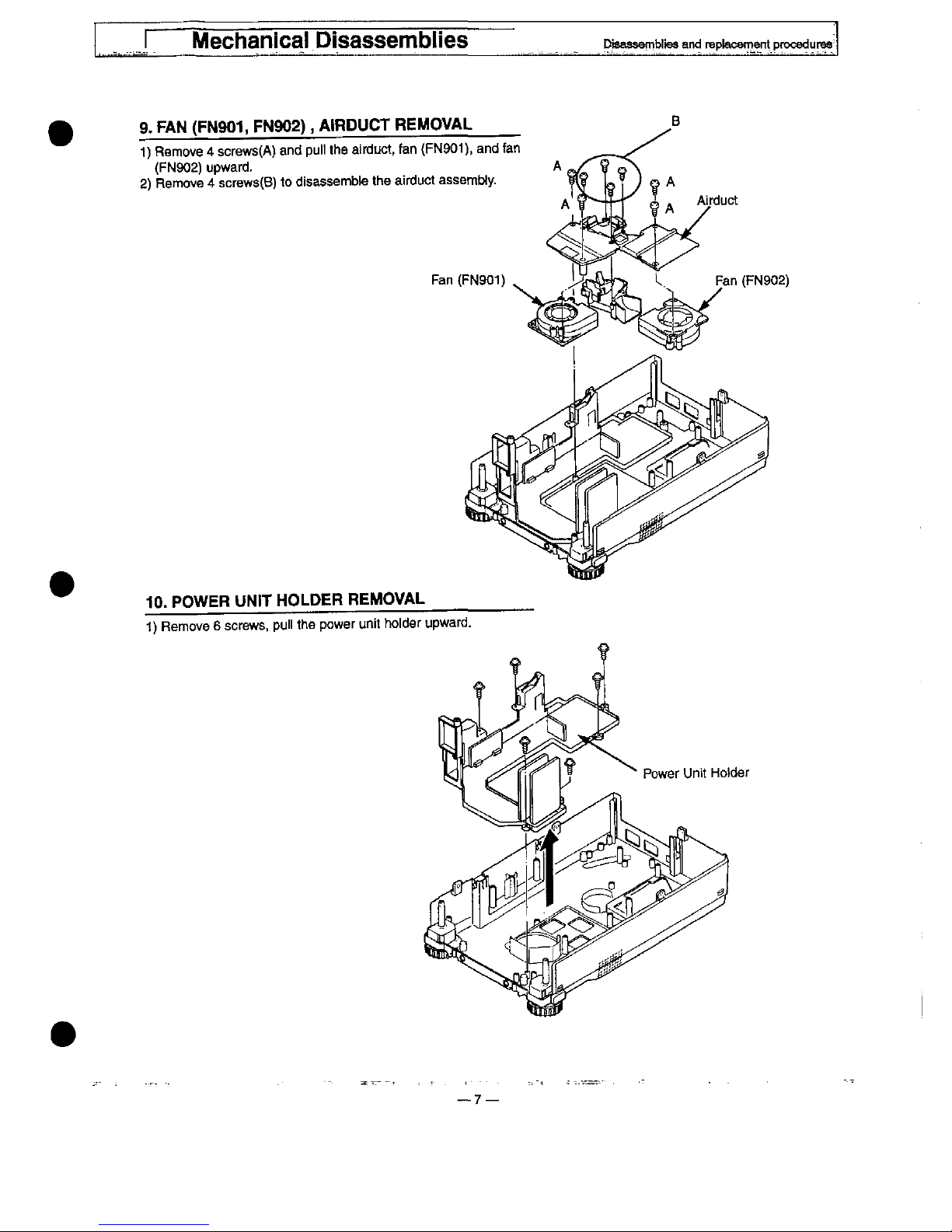
9.
FAN
(FN901,
FN902),
MRDUCT
REMOVAL
1)
Remove 4 screws(A)
and
pu!)
the
airduct,
fan
(FN901).
and
fan
(FN902)
upward.
2)
Remove 4 screws(B)
to
disassembte
the
airduct
assembty.
Fan
(FN901)
10.
POWER
UN)T
HOLDER
REMOVAL
1)
Remove 6 screws,
pu!)
the
power
unit
ho)der
upward.
7—
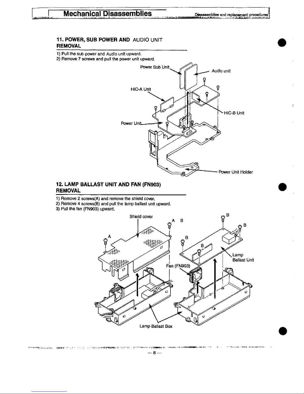
11.
POWER,
SUB
POWER
AND
AUDIO
UN)T
REMOVAL
1)
Pu!)
the
sub-power
and
Audio
unit
upward.
2)
Remove 7 screws
and
pu))
the
power
untt
upward.
Audio
ufift
HtC-A
Unit
Power
Uni
HJC-B
Unit
flower
Unit
Hotder
12.
LAMP
BALLAST
UNn-
AND
FAN
(FN903)
REMOVAL
1)
Remove 2 screws(A)
and
remove
the
shield
cover.
2)
Remove 4 screws(B)
and
puii
the
iamp
batiast
unit
upward.
3)
Put)
the
fan
(FN903)
upward.
Optical
unit
Disassemblies
Dst^semb^ias
and
raptaceme^pfpcedurMJ
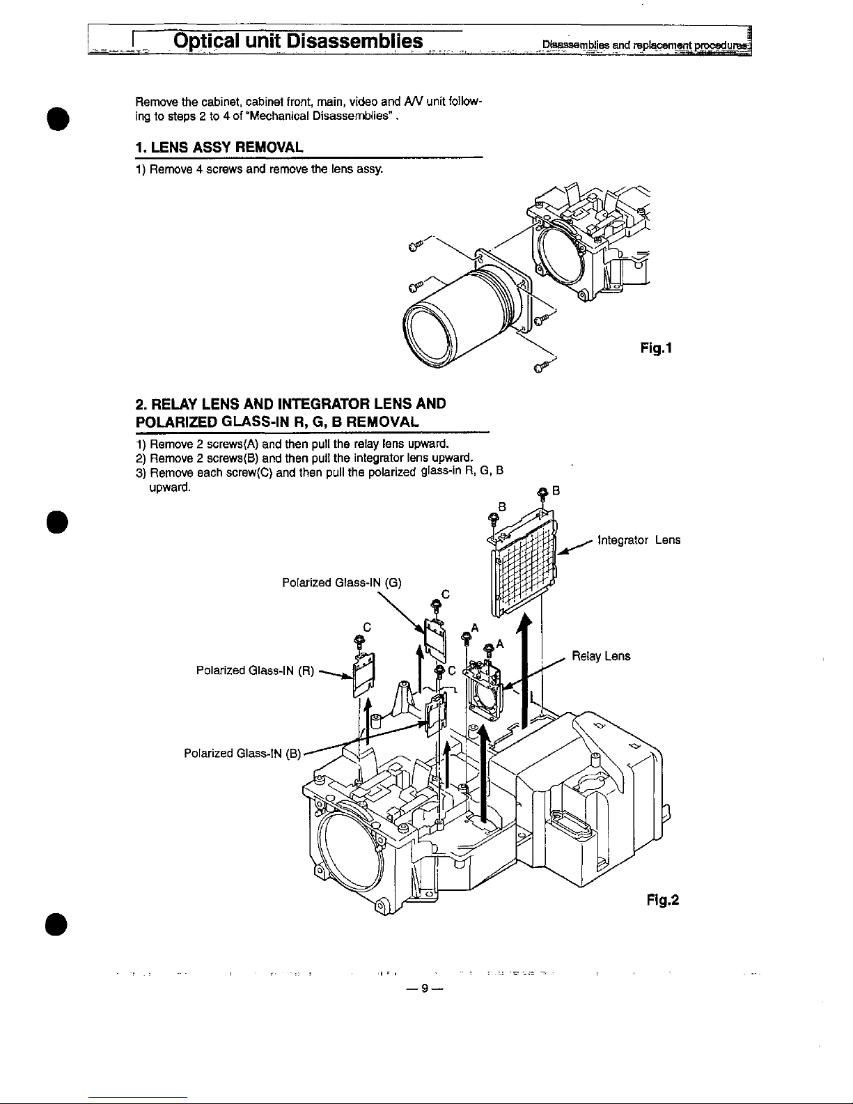
Remove
the
cabinet,
cabinet
front,
main,
video
and
A/V
unit
foitow-
ing
to
stops 2 to 4 of
"Mechanical
Disassembles".
1.
LENS
ASSY
REMOVAL
1)
Remove 4 screws
and
remove
the
tens
assy.
Fig.1
2.
RELAY
LENS
AND
tNTEGRATOR
LENS
AND
POLAR)ZED
GLASS-)N
R,
G, B REMOVAL
1)
Remove 2 screws(A)
and
then
putt
the
re!ay
tens
upward.
2)
Remove 2 screws(B)
and
then
put!
the
integrator
!ens
upward.
3)
Remove
each
screw(C)
and
then
pu!!
the
po)arized
gfass-in
R,
G,
B
upward.
Pofarized
G!ass-)N
(G)
Po)arized
G)ass-!N
(R)
Polarized
G'ass-tN
(B)
—9
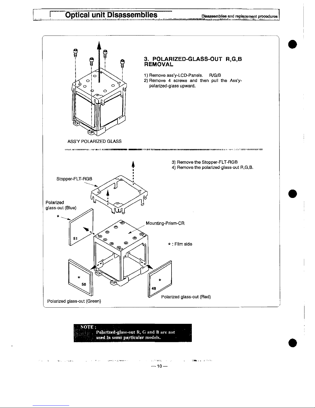
3.
POLAR!ZED-GLASS-OUT
R,G,B
REMOVAL
1)
Remove
ass'y-LCD-Panets.
R/G/B
2)
Remove 4 screws
and
then
pu!!
the
Ass'y-
po!arized-g!ass
upward.
ASS'Y
POLARfZED
GLASS
3)
Remove
the
Stopper-FLT-RGB
4)
Remove
the
po)arized-g)ass-out
R,G,B.
Po)arized
g
[ass-cut
(B)ue)
Mounting-Prism-CR
*
:
F[)m
side
Po)ar!zed
g)ass-out
(Green)
Po)arized
g)ass-out
(Red)
Po!H^iMd-g!it';s-out
R, G and B are
not
used
in
some
parMcutar
modet'i.
10—
Optica)
unit
DisassembHes
Diaasaerr)b)fes
and
repi^en^nt
procedurM
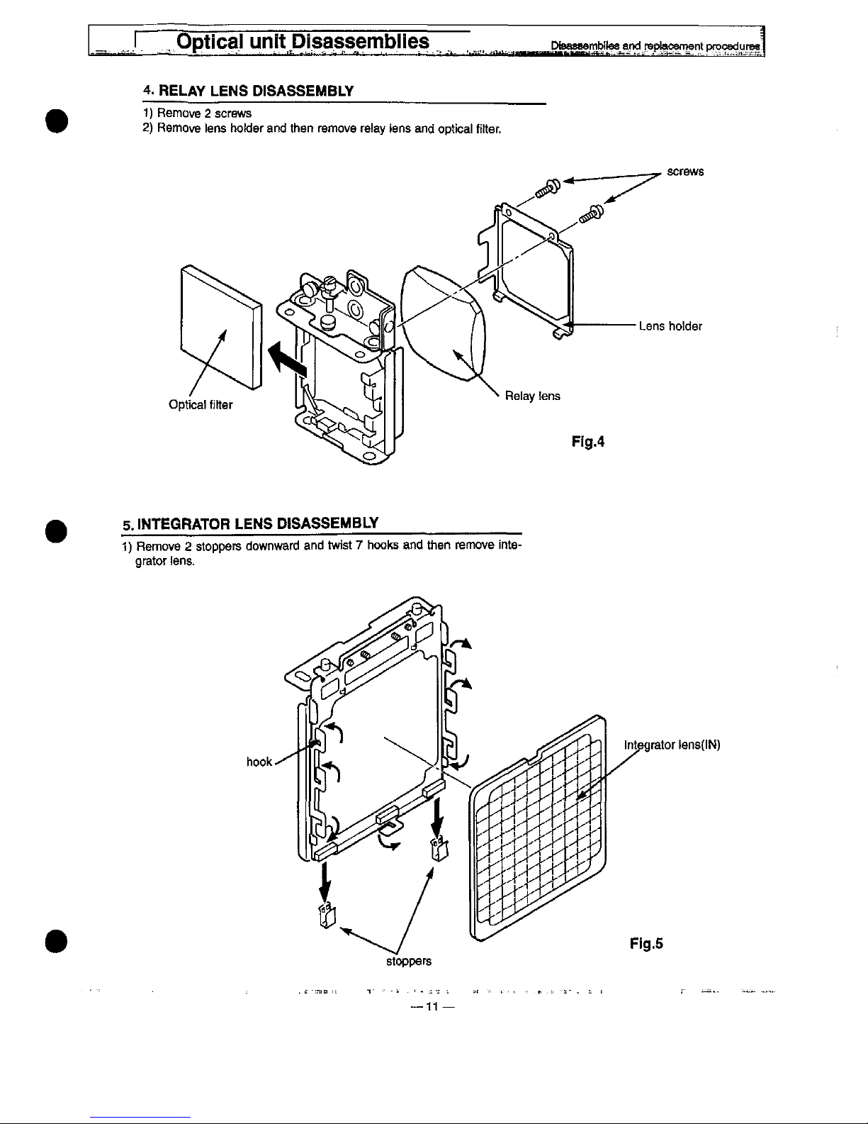
4.
RELAY
LENS
D)SASSEMBLV
1)
Remove 2 screws
2)
Remove
tens
ho!der
and
then
remove
re!ay
tens
and
optica)
fitter.
screws
Lens
hotder
5.
)NTEGRATOR
LENS
DtSASSEMBLY
1)
Remove 2 stoppers
downward
and
twist 7 hooks
and
then
remove
inte-
grator
iens.
hook
integrator
iens(iN)
Fig.5
stoppers
11
Opticat
unit
Disassemblies
DsassembEies
and
reptacement
procedures
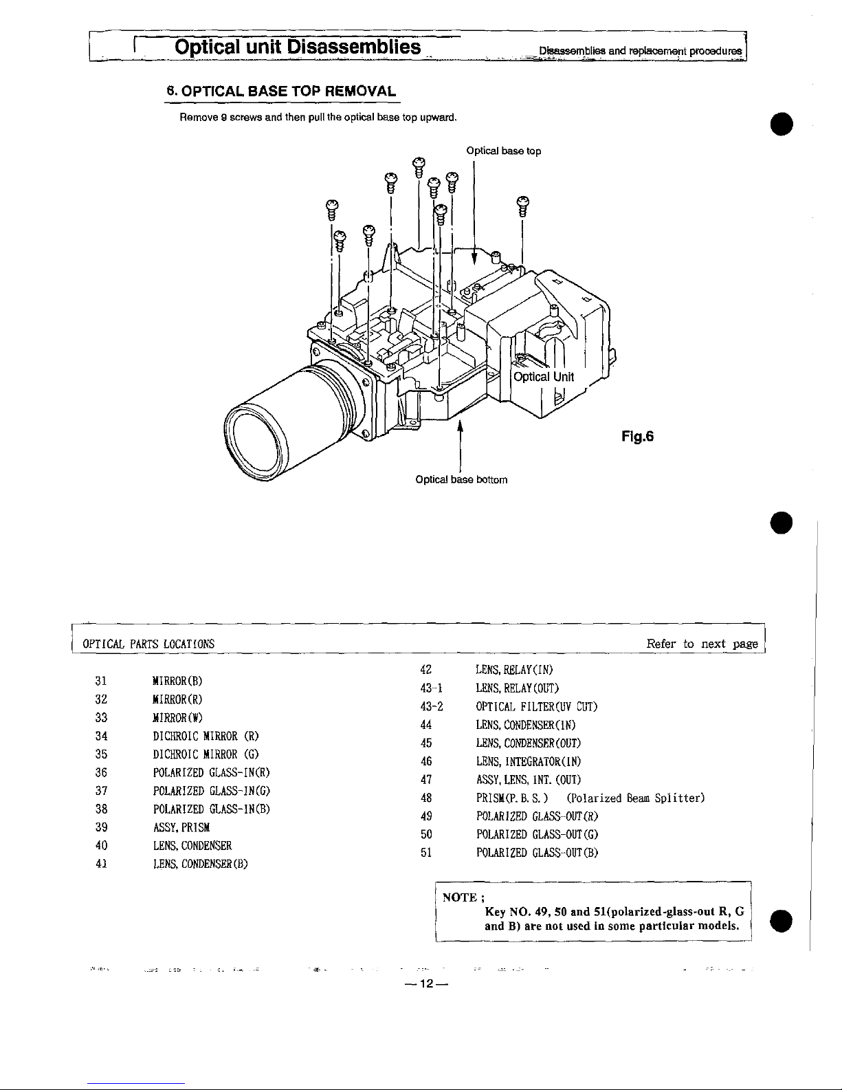
6.
OPTtCAL
BASE
TOP
REMOVAL
Remove 9 screws
and
then
pu!!
the
optica)
base
top
upward.
Optica)
base
top
Fig.6
OPrfCAL
31
32
33
34
35
36
37
38
39
40
41
PARTS
LOCATES
MIRROR(B)
MIRROR(R)
MIRROR(W)
DICHROIC
MIRROR
(R)
DICHROIC
MIRROR
(G)
POLARIZED
GLASS-IN(R)
POLARIZED
GLASS-IN(G)
POLARIZED
GLASS-IN(B)
ASSY.PRISM
LENS.CONDENSER
LEKS.CONDENSER(B)
42
43-1
43-2
44
45
46
47
48
49
50
51
Refer
to
next.
page
LE^.
RELAY(IN)
LENS.RELAY(OUT)
OPTICAL
FILTER(UV
CUT)
LENS.CONDENSER(IN)
LENS.CONDENSER(OUT)
LENS,INTEGRATOR(IN)
ASSY.LENS.INT.(OUT)
PRISM(P.B.S.)
(Polarized
Beam
Splitter)
POLARIZED
GLASS-OUT(R)
POLARIZED
GLASS-OUT(G)
POLARIZED
GLASS-OUT(B)
NOTE;
Key
NO.
49,
50
and
51(polarixed-g!ass-out
R,
G
and
B)
are
not
used
in
some
particular
modets.
12—
L
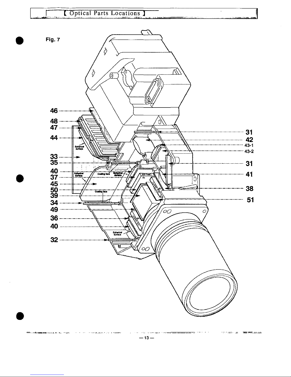
Optical
Parts
Locations
J
—13
Optical
unit
Disassembles
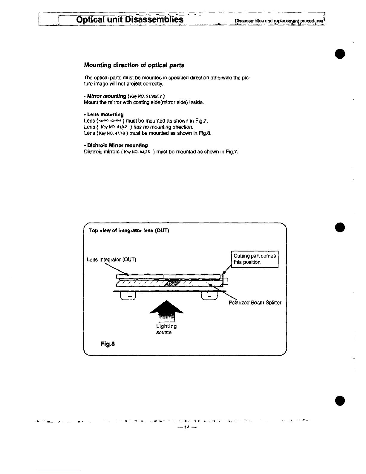
Mounting
direction
of
optical
parts
The
optica!
parts
must
be
mounted
in
specified
direction
otherwise
the
pic-
ture
image
wii)
not
project
correctty.
-
Mhror
mounttna
('<ey
No. 3 j/sz/ss)
Mount
the
mirror
wtth
coating
side(mtrror
side)
inside.
-
Lent
mounttng
Lens
('<^Mo.w^<s)
must
be
mounted
as
shown
in
Fig.7.
Lens(
Kef
Mo.-4^42
)
has
no
mounting
direction.
Lens
(Key
No.
47/49)
must
be
mounted
as
shown
in
Fig.8.
-
Dtchrotc
Mtnw
mounting
Dichrok:
mirrors
(Key
wo.
34^35
)
must
be
mounted
as
shown
in
Fig.7.
Top
view
of
integrator
tena
(OUT)
Lens
integrator
(OUT)
^
/
.^
.
^
Cutting
part
comes
this
position
Potarfzed
Beam
Spiftter
Lighting
source
Fig.8
14—
LCD
PANEL
REPLACEMENT
^s^
-^:
-
*-
Disassembfies
and
roptacemefTt
procadures
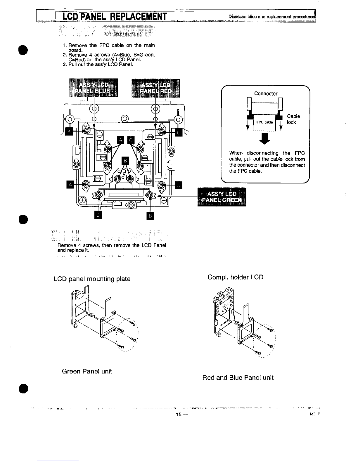
1.
Remove
the
FPC
cab)e
on
the
main
board.
2.
Remove 4 screws
(A=B)ue,
B=Green,
C=Red)
for
the
ass'y
LCD
Pane).
3.
Pu)i
out
the
ass'y
LCD
Pane!.
Remove 4 screws,
then
remove
the
LCD
Pane)
and
rep)ace
it.
LCD
pane)
mounting
p!ate
^
Green
Pane)
unit
CompL
hotder
LCD
Red
and
B)ue
Pane!
unit
15
MF
F

Lamp
assly
reRJacement
tf
the
tamp
fa!)s
to
come
on
and
the
tamp
reptacement
indicator
on
the
projector
tight
)s
orange,
you
must
rep)ace
the
tamp.
^
For
continued
safety,
rep!ace
with a tamp
assembly
of
the
same
type.
part
NO.
6102822755
^
Aiiow
the
projector
to
coo!
for
at
!east
45
minutes
before
you
open
the
tamp
cover.
The
inside
of
the
projector
can
become
very
hot.
^
Do
not
drop
the
iamp
module
or
touch
the
g!ass
buib!
The
giass
can
shatter
and
cause
injury.
<t
FoJ!ow
these
steps
to
roptace
the
iampassombtv.
1.
Turn
off
the
projector
and
a!)ow
the
projector
to
coo)
thoroughty.
2.
Disconnect
the
AC
cord
from
the
projector.
3.
Remove
screw
with a screwdriver
and
remove
the
tamp
cover.
4.
Remove 2 screws
with a screwdriver
and
pu)!
out
the
[amp
assembly
by
grasping
the
handle.
5.
Roptace
the
)amp
assemb)y-
6-
Tighten 3 screws
to
secure
the
)amp
cover
to
the
tamp
assemb)y.
7.
Connect
the
detachable
AC
cord
to
the
projector.
8.
Reset
the
)amp
rep!acement
monitor
timer.
(Refer
to
next
page.)
Turn
off.
Remove
AC
cord
and
wait
46
minutea
before
open
this
tamp
cover.
^
Refer
owner's
manua!
for
reptacing
the
tamp.
Reptace
with
same
type
tamp.
Etsindra
)'apparei).
Entew
te
Cordon
secteuf
et
attandfe
46
mtrnrtes
avant
^
d'ouvrir
ce
couvercte.
Se
raportBr
au
moda
d'amptoi
pour
ramptacer
[a
)ampe.
Remp)acar
ta
)ampe
par
un
mode)
identiqua.
Schahen
Sie
den
Projektof
aua.
z!ehen
Sie
das
Stromkabe!
aus
dem
Projektor
^
und
warten
Sio
46
Minuten.
bevof
Sfe
den
Projektor
offnen.
LeMn
Sie
im
Manuat
im
Kapite!
'Lampenwechsef'
die
Detaifs
nach.
Benutxen
Sie
nur
eine
offizt9)[e
Ersamampe
des
gteichon
typs-
^
Apague
e!
sparato.
Deeconecte
et
caMa
da
fad y a^pera
45
minutos
antes
t
de
abrir
)a
tapa.
Consutia
e!
manuat
de
inairuccioDaa
para
cambiof
ta
)ampara.
Csmbie
ta
)amparH
por
otra
de)
nnsfno
tipo.
Stang
av
projektom.
Dra
ur
Kontatcten
oeh
vanta
46
minutar
innan
Ni
oppnar
^skydoet.
VthanviMft^instruk^on^bokeninnan
Mbyterfampa.
Anvand
sammatypaviampa.
Shik
for
projaktoran.
Fjam
natfedningen
frB
stikkontaktan
og
vent
45
fntn
tfar
kabinettet
abnes-
Se i brugsanvisningen,
f0f
tampen
skiftes.
Brngsamme
type)ampe.
0
Lamp
Assembty
Lamp
cover
WARN)NG
ALLOW
TO
COOL
BEFORE
ATTEMPTING
TO
CHANGE
THE
LAMP.
USE
ONLY
REPLACEMENT
LAMP
PART
N0.6102822755
—16—
Lamp
ass'y
replacement
^
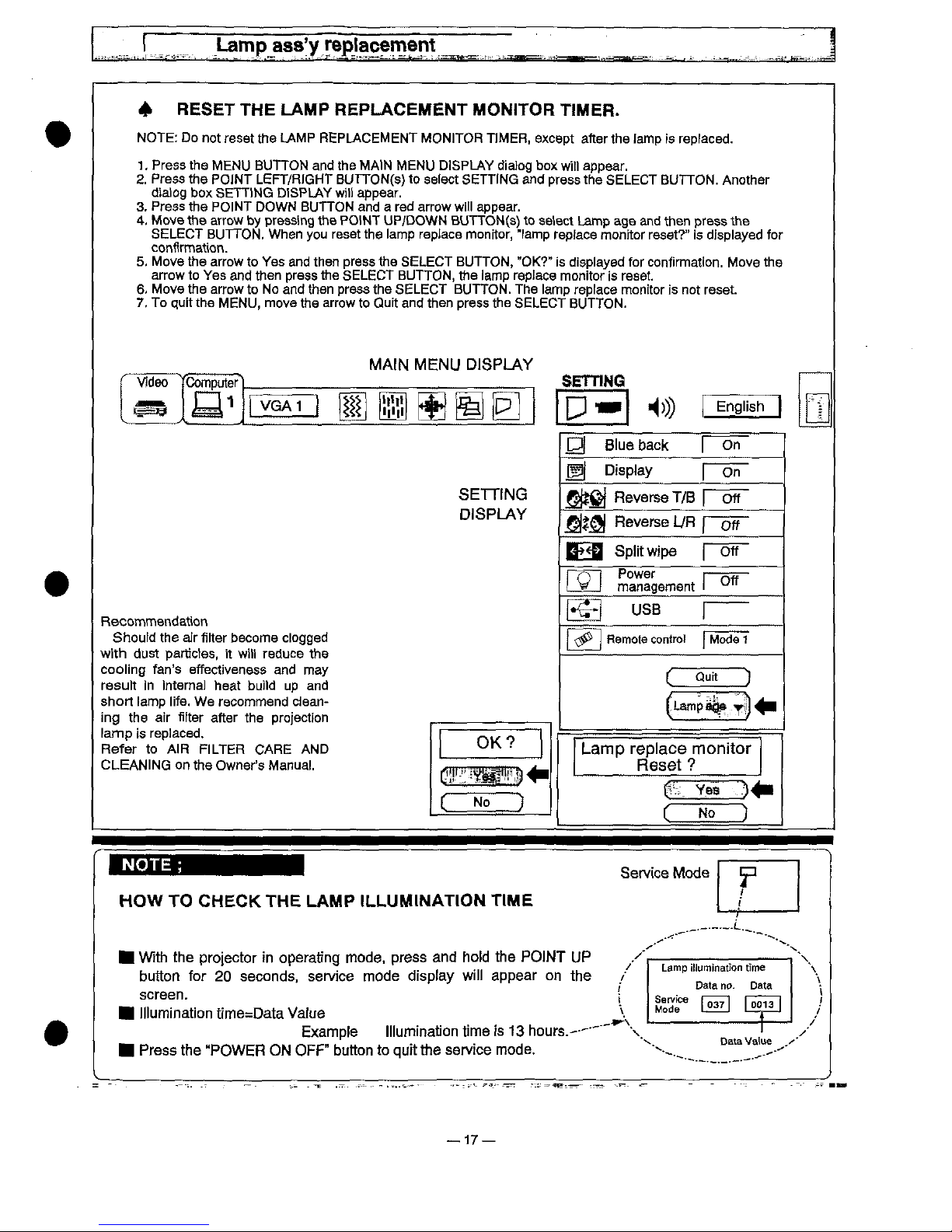
RESET
THE
LAMP
REPLACEMENT
MON)TOR
T!MER.
NOTE:
Do
not
reset
the
LAMP
REPLACEMENT
MONITOR
T)MER,
except
after
the
tamp
is
replaced.
1.
Press
the
MENU
BUTTON
and
the
MA)N
MENU
DISPLAY
dia)og
box
wit)
appear.
2.
Press
the
POINT
LEFT/RiGHT
BUTTON(s)
to
select
SETT)NG
and
press
the
SELECT
BUTTON.
Another
alaiog
box
SETTtNG
DiSPLAY
witi
appear.
3.
Press
the
PO)NT
DOWN
BUTTON
and a red
arrow
wi!i
appear.
4.
Move
the
arrow
by
pressing
the
FONT
UP/DOWN
BUTTON(s)
to
setect
Lamp
age
and
then
press
the
SELECT
BUTTON.
When
you
reset
the
tamp
roptace
monitor,
"lamp
repface
monitor
reset?"
is
displayed
for
confirmation.
5.
Move
the
arrow
to
Yes
and
then
press
the
SELECT
BUTTON,
"OK?"
is
displayed
for
confirmation.
Move
the
arrow
to
Yes
and
then
press
the
SELECT
BUTTON,
the
lamp
repface
monitor
is
reset.
6.
Move
the
arrow
to
No
and
then
press
the
SELECT
BUTTON.
The
iamp
repface
monitor
is
not
reset.
7.
To
quit
the
MENU,
move
the
arrow
to
Quit
and
then
press
the
SELECT
BUTTON.
MAtN
MENU
D)SPLAY
5ETDNG
English
[Dj
B)ue
back
Display
SETTING
DISPLAY
Reverse
T/B
j^<^
Reverse
L/R
p-ofT
B^
Split
wipe
Power
management
Recommendation
Should
the
aJr
fitter
become
dogged
with
dust
partictes.
it
wiH
reduce
the
cooiing
fan's
effectiveness
and
may
resu)t
in
internal
heat
bui)d
up
and
short
tamp
iife.
We
recommend
dean-
ing
the
air
fitter
after
the
projection
tamp
is
repiaced.
Refer
to
AtR
FILTER
CARE
AND
CLEANING
on
the
Owner's
Manual.
OK?
L'^-
i
^
^^.^^
No
)
US8
Hemote
contro!
Mode
1
(Quit
)
Lamp
rep!ace
monitor
Reset
?
No
NOTE:
HOW
TO
CHECK
THE
LAMP
)LLUMtNATtON
TtME
F
t
With
the
protector
in
operating
mode.
press
and
hotd
the
POINT
UP
button
for
20
seconds,
service
mode
disptay
wiii
appear
on
the
screen.
iiiumination
time=Data
Vatue
Exampte
)iiumination
time
is
13
hours.--"
Press
the
"POWER
ON
OFF"
button
to
quit
the
service
mode.
/
Lamp
itfumination
time
\
;'
Data
no.
Data
',
^r
u^]
u^)
^^
t————-^-j
/
Data
Vatue
.^'
17—
SAFETY
)NSTRUCT)ONS
^
SAFETY
PRECAUTIONS]
WARN)NG:
The
chassis
of
this
projector
is
isolated
(COLD)
from
AC
)'ne
by
using
the
converter
transformer.
Primary
side
of
the
converter
transformer
and
tamp
power
supply
unit
circuit
is
connected
to
the
AC
line
and
it
is
hot,
which
hot
circuit
is
identified
with
the
iine
in
the
schematic
diagram.
For
continued
product
safety
and
protection
of
personne!
injury,
servicing
shouid
be
made
with
quati-
fied
personnel.
The
foitowing
precautions
must
be
observed:
1.
An
isolation
transformer
shouid
be
connected
in
the
power
iine
between
the
projector
and
the
AC
iine
before
any
service
is
performed
on
the
projector.
2.
Compty
with
a!i
caution
and
safety-
rotated
notes
provided
on
the
cabinet
back,
cabinet
bottom,
inside
the
cabinet
or
on
the
chassis.
3.
When
replacing a chassis
in
the
cabinet,
always
be
certain
that
aii
the
protective
devices
are
instated
property,
such
as
control
knobs,
adjustment
covers
or
shiejds
and
barriers.
DO
NOT
OPERATE
TH)S
PROJECTOR
WtTH-
OUT
THE
PROTECT!VE
SHIELD
)N
POSmON
AND
PROPERLY
SECURED.
4.
Before
replacing
the
cabinet
cover,
thoroughiy
inspect
the
inside
of
the
cabinet
to
see
that
no
stray
parts
or
toots
have
been
iett
inside.
Before
returning
any
projector
to
the
customer,
the
service
personnel
must
perform
the
following
safety
checks
and
be
sure
that
it
is
compieteiy
safe
to
operate
without
danger
of
etectricai
shock.
[PRODUCT
SAFETY
NOT)CE
]
Product
safety
should
be
considered
when a component
replacement
is
made
in
any
area
of
the
projector.
Components
indicated
by a mark
(A)
in
the
parts
iist
and
the
schematic
diagram
designate
components
in
which
safety
can
be
of
speciai
significance,
it
is,
therefore,
particularly
recommended
that
the
replace-
ment
of
these
parts
must
be
made
by
exactly
the
same
parts.
t
SERVICE
PERSONNEL
WARNING
]
Eye
damage
may
resutt
from
direct)y
viewing
the
iight
produced
by
the
Lamp
used
in
this
equipment.
Always
turn
off
Lamp
before
opening
cover.
uttraviotet
radiation
eye
protection
required
during
this
servicing.
Never
turn
the
power
on
without
the
iamp
to
avoid
etectrfc-
shock
or
damage
of
the
devices
since
the
stabilizer
generates
high
voitages(
=
25kV)
at
its
start.
Since
the
iamp
is
very
high
temperature
during
units
operation.
Replacement
of
the
!amp
should
be
done
at
ioast
one
hour
after
the
power
has
been
turned
off,
to
atiow
the
lamp
coo)
off.
r
DO
NOT
ATTEMPT
TO
SERV!CiNG
THE
REMOTE
CONTROL
UNtT.
]
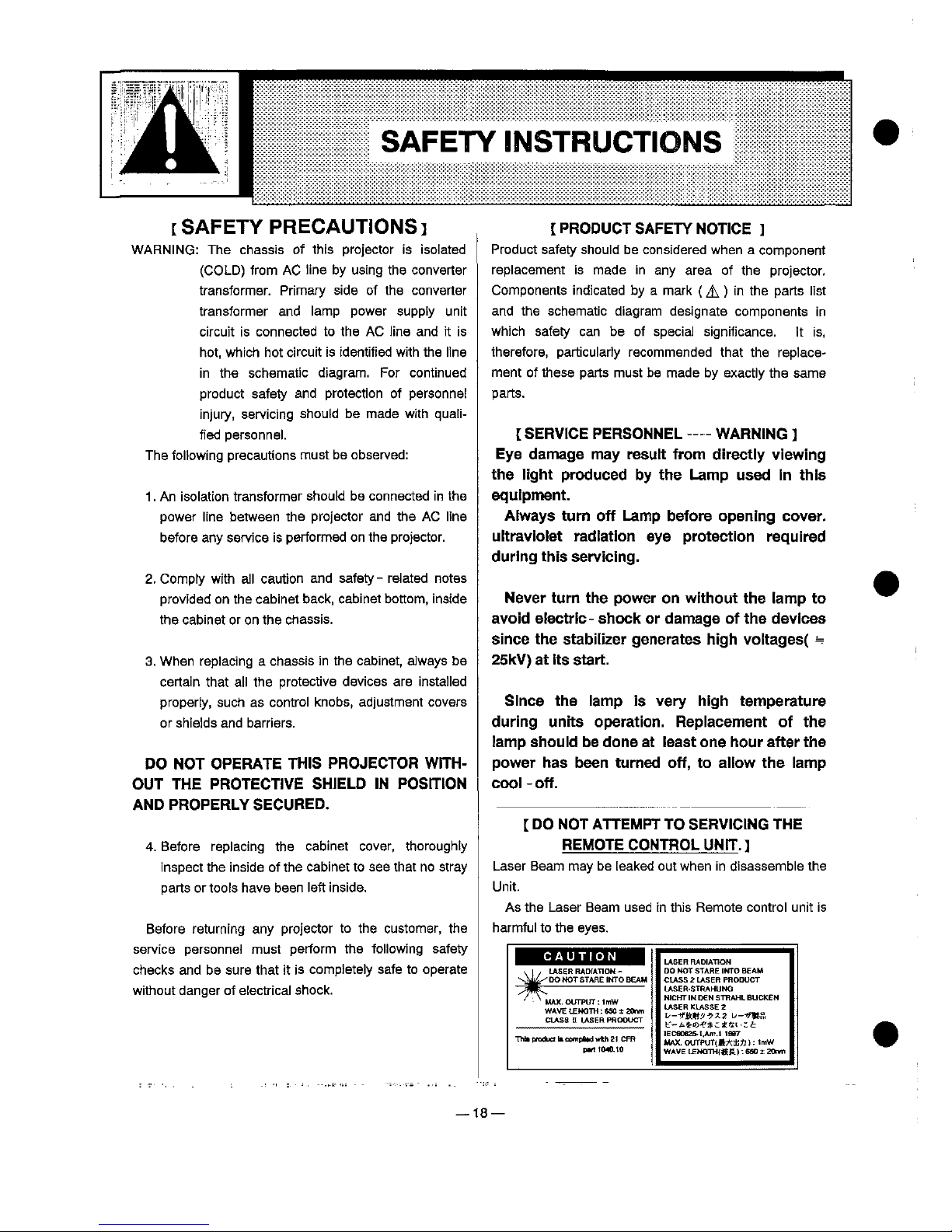
Laser
Beam
may
be
[eaked
out
when
in
disassemble
the
Unit.
As
the
Laser
Beam
used
in
this
Remote
control
unit
is
harmful
to
the
eyes.
j
CAUTtON
t
'.!/
LASER
RADfATION-
-^^
00
NOT
STARE
'MTO
BEAM
^^
'
'
MAX.
OUTPUT:
tmW
WAVE
tBMQTH:
MOt
BOnm
CLASS H LASER
PRODUCT
ptfttfMOJO
DO
MOT
STARE
!MTO
BEAM
CLASS 2 LASER
PRODUCT
LASERSTRAHUMQ
MCHT
)M
DEM
STRAHL
6UCKEM
LASER
KLASSE
2
L—V&tt?7^2
L.--'^.
)i-^%f^^^t<[t.^^
)ECeoe2E-t.Am.t
)9B7
MAX.
OUTPUT^A^JJ):
'mW
WAVE
LEMQTmKS
t:
6SO ± 20nm
18—
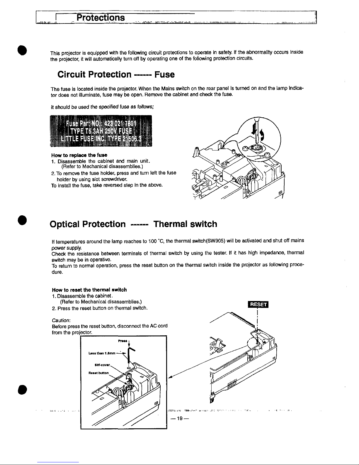
Protections
This
projector
is
equipped
with
the
following
circuit
protections
to
operate
in
safety,
if
the
abnormatity
occurs
inside
the
projector,
it
wiii
automatical
turn
off
by
operating
one
of
the
foHowing
protection
circuits.
Circuit
Protection
Fuse
The
fuse
is
located
inside
the
projector.
When
the
Mains
switch
on
the
rear
pane)
is
turned
on
and
the
tamp
indica-
tor
does
not
itiuminate.
fuse
may
be
open.
Remove
the
cabinet
and
check
the
fuse.
it
shouid
be
used
the
specified
fuse
as
foftows;
How
to
reptace
the
fuae
1.
Disassemble
the
cabinet
and
main
unit.
(Refer
to
Mechanica)
disassembles.)
2.
To
remove
the
fuse
hotder,
press
and
turn
ieft
the
fuse
hoider
by
using
slot
screwdriver.
To
insta!!
the
fuse.
take
reversed
step
in
the
above.
Optica)
Protection
Thermai
switch
if
temperatures
around
the
tamp
reaches
to
100
'C.
the
thermal
switch(SW905)
wiii
be
activated
and
shut
off
mains
power
suppfy.
Check
the
resistance
between
terminais
of
thermal
switch
by
using
the
tester,
if
it
has
high
impedance,
thermal
switch
may
be
in
operative.
To
return
to
norma)
operation,
press
the
reset
button
on
the
thermal
switch
inside
the
projector
as
following
proce-
dure.
How
to
reset
the
therma)
awttch
1.
Disassembte
the
cabinet.
(Refer
to
Mechanical
disassembles.)
2.
Press
the
reset
button
on
thermal
switch.
Caution;
Before
press
the
reset
button,
disconnect
the
AC
cord
from
the
projector_____
______
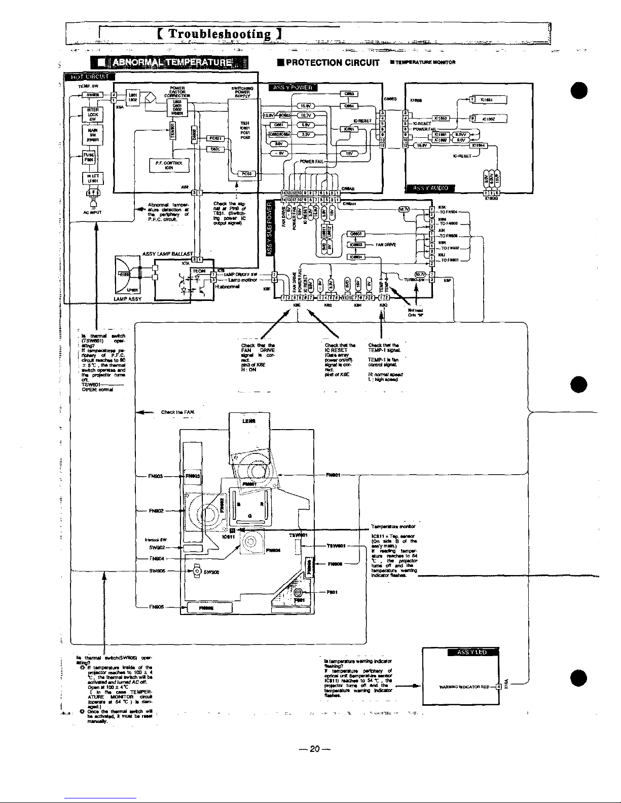
*C,
thtthenn*i<w!M^wMb*
*ct^)Md
^)d
funttd
AC
off.
Optn*t)00±<^
[in
tht
MM
TEMPCR-
ATUREMOMTORdfcu)'
t«xt^t « M
'C ) h
d^^
t0<d.j
One*
tM
ttxnntf
Mttc^
wO
bt
tOhmttd. f muM
b*
m*t
21
--22—
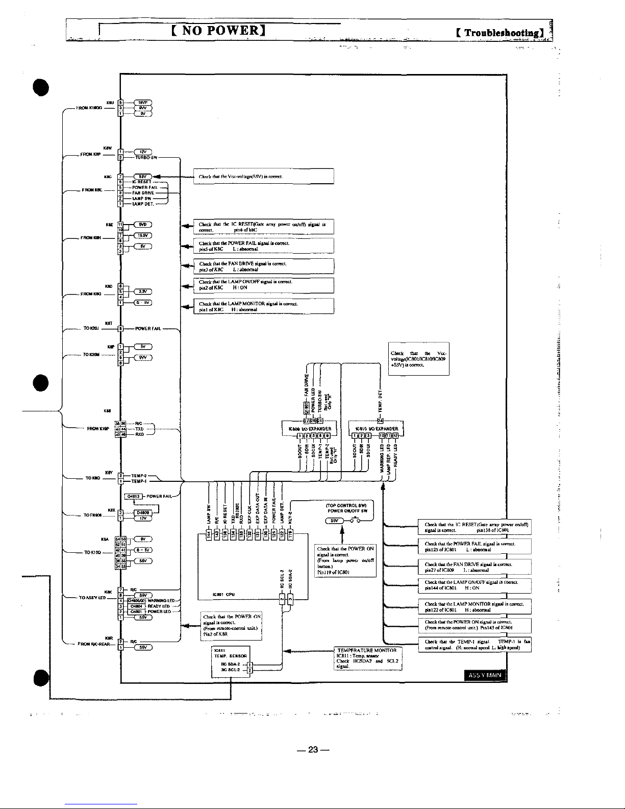
^
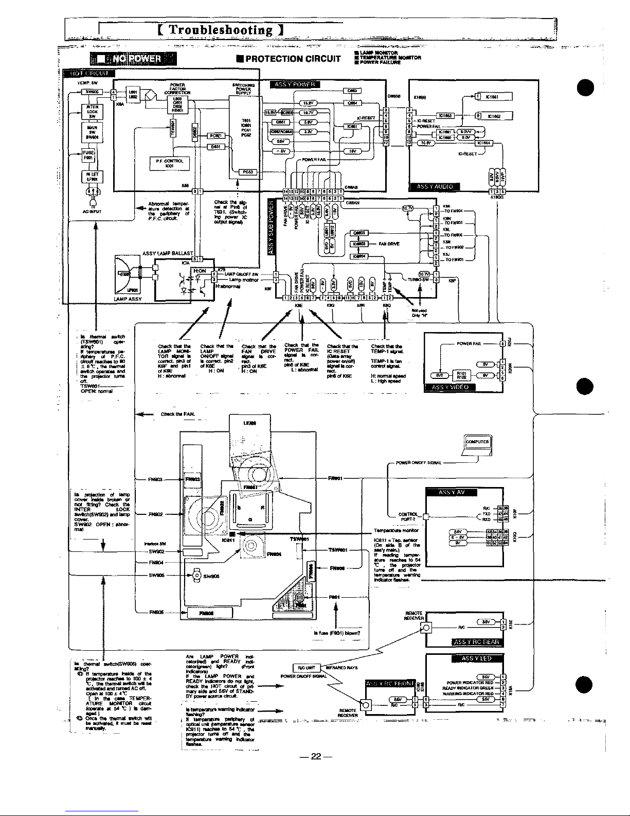
NO
POWER]
--23—
[NO
SOUND]
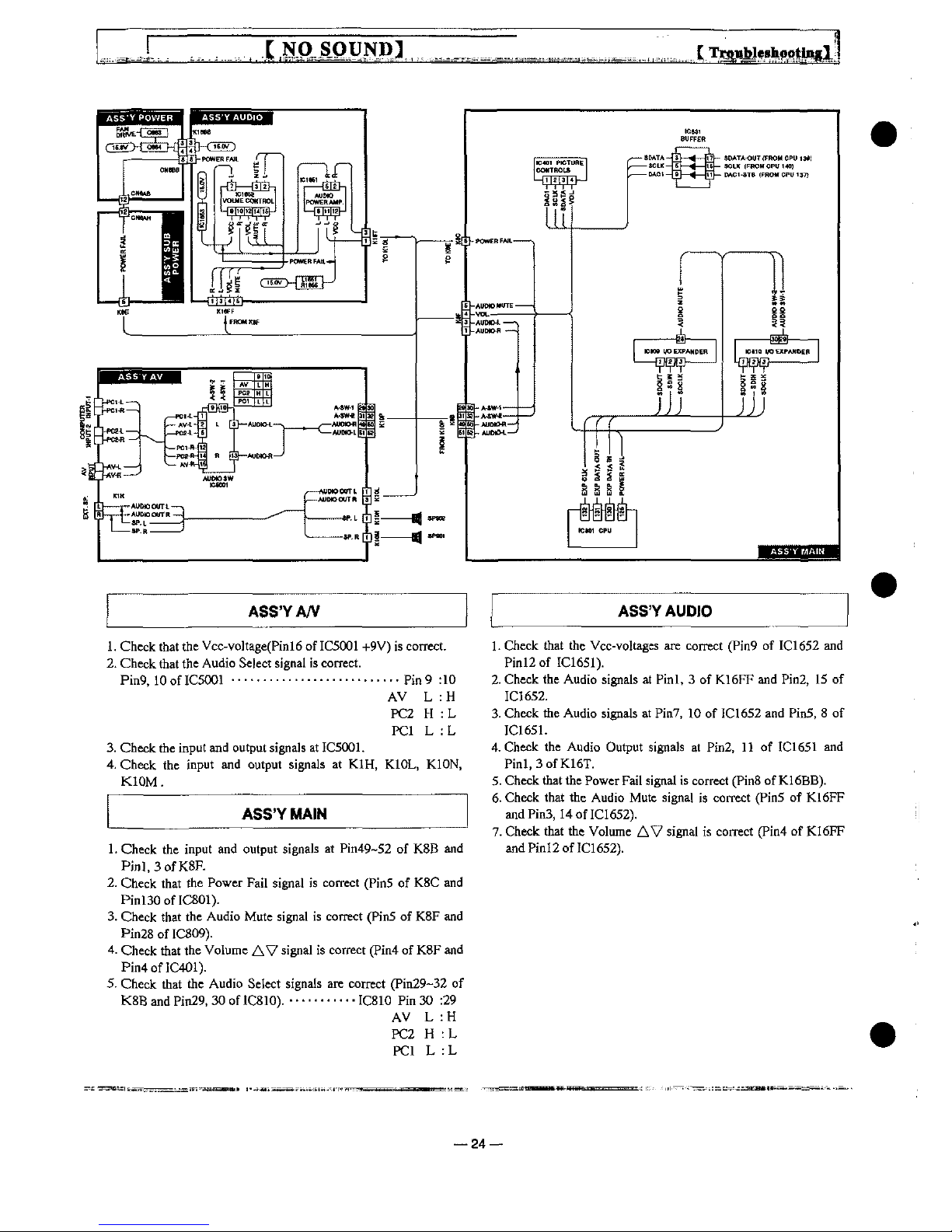
ASS'YA/V
ASS'YAUDiO
1.
Check
that
the
Vcc-vo)tage(Pinl6
of
IC5001
+9V)
is
correct.
2.
Check
that
the
Audio
Seject
signat
is
correct.
Pin9,10
of
IC5001
...........................
pin 9 :10
AV L :H
PC2 H :L
PC1 L :L
3.
Check
the
input
and
output
signals
at
IC5001.
4.
Check
the
input
and
output
signats
at
K1H,
K.10L,
K10N.
K10M.
ASS'YMAtN
1.
Check
the
input
and
output
signals
at
Pin49-52
of
K8B
and
PinI.3ofK8R
2.
Check
that
the
Power
Fail
signal
is
correct
(Pin5
of
K8C
and
Pinl30
of
IC801).
3.
Check
that
the
Audio
Mute
signal
is
correct
(Pin5
of
K8F
and
Pin28ofIC809).
4.
Cheek
that
the
Volume
AV
signal
is
correct
(Pin4
of
K8F
and
Pin4ofIC401).
5.
Check
that
the
Audio
Setect
signals
are
correct
(Pin29-32
of
K8B
and
Pin29,
30
ofICSlO).
...........
IC810
Pin
30
:29
AV L :H
PC2 H :L
PC1 L :L
1.
Check
that
the
Vcc-voltages
are
correct
(Pin9
of
IC1652
and
Pinl2
of
IC1651).
2.
Check
the
Audio
signals
at
Pinl. 3 of
K16FF
and
Pin2.
15
of
IC1652.
3.
Check
the
Audio
signals
at
Pin7,
10
of
IC1652
and
Pin5. 8 of
IC1651.
4.
Check
the
Audio
Output
signals
at
Pin2,
11
of
IC1651
and
Pinl,3ofK16T.
5.
Check
that
the
Power
Fail
signat
is
correct
(Pin8
of
K16BB).
6.
Check
that
the
Audio
Mute
signal
is
correct
(Pin5
of
K16FF
and
Pin3,14
of
IC1652).
7.
Check
that
the
Volume
AV
signal
is
correct
(Pin4
of
K16FF
and
Pinl2
of
IC1652).
24
 Loading...