

Sanyo PLC-XP18N,PLC-XP18E,PLC-XP18B Service Manual
SERViCE
MANUAL
Mu^-med!a
Projector
S4^o
F/^
MO.
MODEL
NO.
PLC-XP18N
(U.S.A.
.Canada)
PLC-XP18E
(Europe,
Asia,
Africa,
M.E.)
PLC-XP18B
(U.K.)
ORIGINAL
VERSION
Chassis
No.
MH6-XP18NOO
PLC-XP18EOO
PLC-XP18BOO
NOTE:Match
the
Chassis
No.
on
the
unit's
back
cover
with
the
Chassis
No.
in
the
Service
Manuaf.
tf
the
Ortgfnai
Version
Service
Manua!
Chassis
No.
does
not
match
the
unit's,
additional
Service
Literature
is
required.
You
must
refer
to
"Notices"
to
the
Original
Service
Manual
prior
to
servicing
the
unit.
Give
complete
"Chassis
NO."
for
parts
order
or
servicing,
ft
!s
shown
on
the
rating
sheet
on
the
cabinet
of
the
Projector.
Specifications
Disassemblies
Mechanica
Optical
urn
LCD
pane)
Assy
tamp
Safety
Instruc
Circuit
Protec
Troubleshooti
Waveforms
-
Alignment
Prc
Service
ad
Electrical
a
Focus
adju.
Convcrgen
Product
Code
CONTENTS
and
Replacement
Procedures
disassemblies
--....-.-...--
t
disassemblies
-.........-.--
replacement
.........
replacement
..----.....-..--
ions
""..-..
ions............--.-....."
ng
........................
ustments
.......-..--.
djustments
.."--......-""
stments
--.-..""........"
ce
adjustment
."--......."
1
12207740
:
PLC-XP18N
1
12207840
:
PLC-XP18E
1
12207842
:
PLC-XP18P
................
^
.............
3^17
.............
9^14
...............
15
............^6-^7
...............
^g
...............
19
............
20-27
............
30-43
............
31"-32
...............
^o
MH6AA
PH6AA
PH6CA
mtegratoT
lens
adjustment
---..-.----.......
Relay
lens
adjustment
-..----......""..---
Polarized
glass
adjustment
.--.....--.-..---.
CPU
input/output
port
functions
---...-.........
Maintenance
- - -
---..-..--........."----....-
Notes
on
schematic
diagram
........"---.....-
Parts
-List
..................................
Cabinet,
Chassis
and
Optical
patts
!ist...----..
Electrical
parts
list
...".......----..---....
Parts
location
and
PWB
pattern
diagrams
---....-
Block
diagram
and
Low
power
distribution " "
- -
-
Schematic
diagrams
..........................
REFERENCE
----------
41
..........
43
.......
48-49
.......
5^51
.......
52-79
.......
59-79
..........B1
WO.SM5110206
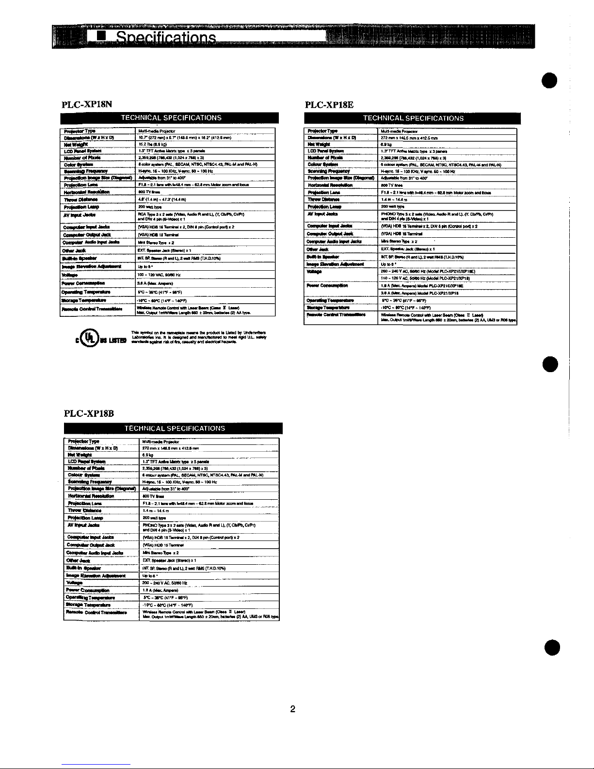
PLC-XP18N
PLC-XP18E
TECHN)CAL
SPEC)F)CAT)ONS
TECHN)CAL
SPEC!F)CAT!ONS
PmtteMfTyp*
NM—tM^tW'MtD)
tMWtt^t
LO)^'*")MtM'
MM^Xfc<M)Mt<
C«)u<)t)"MM
tut)t)t)eR^^*f
^Mtte^Mtt^Btt'fDhtM*))
f^^tan'J^'
Hoftt.XtM
mottttMett
Tttfo^Mtttme*
Pt^at^LtXt^
jtV)nt^tJ**t
CMXtMtM-'nptttJtdtt
Cetxpt^ftMpM^A
CMnp^Me'nf^.'-*'
0)htf*tatt
XXttMatpt-tM'
tnx.t*
HH^ttfto
jM)tt.t«.!)t
^Mt^'
t^)ttC«titM))t«M
Op-^wTtMf^tXM
^tefOtttTttf'HtM
n—ofCemMTuMmM't'
MuM^ttttPn^eMt
'a.7't:7tnm)'E.7'(t*6.6mm)tte.:'f<'!.Emm)
'6.:^tn«.9k^
'^'TtTAettMMtMtM)*
!t3))tn*H
MM^e(7M^Mt'.OM'7M)t3}
t<!o)o't^ttmjPAL.MC*M.MTaC.MTMM.O.)'^L-MtndML-N)
^m<.
16 - 'M
KH^^t^t:. M -
'<M
H!
*t'^Ntfem31')o<M'
F'^-^.Htn.wthh-M.4nm-M.t'm'MofccmMttoem
tMT\t^t
4.t-(t.^)-47^<14.4m)
MOwMttyp.
aC*^pt3.:ttt.(VMt^Autft.atnau.(^.ChM).Ct^)
[Va*)HDattTtm'n*)'a.mmf*'(OonMpo[a'!'
(VOA)MOt'eT*m*^
MntNt^oT^p.
j.t
Exr.atM-^jM'fa^*ti)ti
'MT.MSMm)(R-mj.2tMt)RMSfT^mo%)
Up
tea'
IM-1MWC.MMH.
MAft^.A^f.)
t-C^-C(4t-F-M-F)
-'<^-M-C{K'F-t<C'F)
i^^^^L^^^X^^
t^)*etefT)^
D)t)MtXfon*[W]tH^D)
MtW*^t
t.eo^ttmtfmttn
HMXttfefPOMX
CetCM't^ffM
OMM)t<t)t^()Mney
flatten
)'H<N*«MfC<«Ban^
Mat^MttttM^aMfon
f^tt«M)^f
ThMwDtttMM
Pt^teWenL'ttxt)
^)^J^.
OMttpaMftntM
*)(*);
CemfHt^OtttMtJtttft
C<Mpt)t*rMe)^Jt<<(t
0)h^*«*
MHxtpt-Mr
)-^n-^-.*<)""m"<
<Mt^.
MM^CeM<)Mt^M
Op'!t)'^T*<MMMtHt*
tten)BtTto^n)H«
it^^.CMMT......^
.
MuM-nttttt^t^M
272
mm < '<t.6
mm < 412-6
mm
M^
t.yTFTAetttf^MtM)*
*3fM^*
2.9M.Met7W.<3!(t.aM'7M)!'^
tcoUxft^ttmfP^L.iECAM.'^SC.
NTaC4.43.ML-MtttjRH.-H)
^t)me.'e-tMKHt.V.on).M-")OHz
MhttttNtttm3t'M40^
tMTV!htt
Fl.t-n'Mt^t-M.tmm-tMmmHeMtMmtMtM^
'.4m-t*.4^
MOMMttfp.
tMMH*p't)t^-MOte))ft
{VQA)HDenTtm)tif!tt.D<mt^tCcn)M)pe^)t:
(VaA)
HM
)t1tnntn'
MMSXtto^i;^
EX^.Sp^t^J^fStmom
tm;we^«)(Htt^L),2'MNHMafr^.D.'e%)
upMe*
MO-MOV*c.NMaHtfMaa.fPUmM'EM'i)E)
ne-1ZCVtC.MMm{ModOPLC-XM1^tP1t)
t.tA[Mtn.A^M)Mt^)'^&^<M'EM't)e
MA<MM.)^p^.)Mc<MPLC-)(P2I/)(''^
M:-3t^:f<t'P-t6^)
-)e^-te^:tt4'F-)<e^)
Wt*)tttntmottC<M)M<)*hLtttfBt^!C't<t n Ltttt)
LttOfttodtt
hM. t X
dtOentd
tnd
mtnu^oWtd M m*t<
t^f
u.L.
t*M^
PLC-XP18B
TECHN)CAL
SPECtF)CATfONS
PKt*ttcrTtP*
NMtM^n)f[W!<H)tp)
H^W*t^
[^&httMH^^
^«''t!fOtP6ttt<t
CoteMT^tttOt
tM)mi)f^)fMo)t«M]'
thr^nf)!-*'
^'^
)MM
fOMttaOtf)
HMtMnMtt*M)t)t)en
PM^MMattLMt
Tt^wOtttMe*
'^*eeanU)tntt
^tt^UtJtCttt
CM«))Mttf)t)pumc'Ct
CamptttMOt^mmf*
CM^ot^Jht^topotJ^*
OtfMf^ct
ButttttapM**t
'^9''a.tX«t<HM)MMMtnt
^Mt^t
'^MfeenMmptfon
OptfOt^Tt-ptf^uf*
TMfr'9*
T<«^tr*tjrt
'^^.^MT^^,
HtJM^nttttPn^tetor
27ZmmtMMmn't<'Mmm
M^
'.a'TPTAMhthXmtttn)*
Of^ttt
e.3ae^M{7M.<^m.OM)t7M)0)
ea!tmr.^ttm(f^MO*M.MTac.MTaC<.4a.ML-UtndP)U.-M)
H^nc.t6-'(mKHz.V^^M-'0(!Ht
*<ttt)^tthcm:1'M*M'
*MTVh.tt
F'.t-:.''^.^M.4mm-eM^Hota.mom.ndb=u.
'.<m-)4.<m
aHwMW
PWOn01^)t3!?t*ttftM*o.A))*)R'ndL}.tY.Ch<Pt).CKPf)
<nJD)M4ph(S-VM*<H!tt
(MA}HCei6Ttm<n^t:.MMt[4n(C<ntMtMn))t:
fWA}HDe'6TwmM
MMB<tftoT^)ti;:
EXT.
St^tHttJttf
(attMO) x t
'HT.
9P.
8)t<*e
(R
Md
U.:
x«)
RMS
(T^.[11(<%)
up'c.e'
MO.MovAC,6n<em
1.tA(Mt)LAmpttt)
t-c-M'c(4i'F-es'H
-tO^-M^^-F-KO-F)
^^T^^^^^^^^u
Mechanjca)
D!sassemb)ies
Mechantca)
disassembte
shouid
be
made
following
procedures
in
numencai
order.
Fo!!owing
steps
show
the
basic
procedures,
therefore
unnecessary
step
may
be
ignored.
Cautton:
The
parts
and
screws
shouk)
be
piaced
exactiy
the
same
position
as
the
ongina)
otherwise
)t
may
cause
toss
of
per-
formance
and
product
safety.
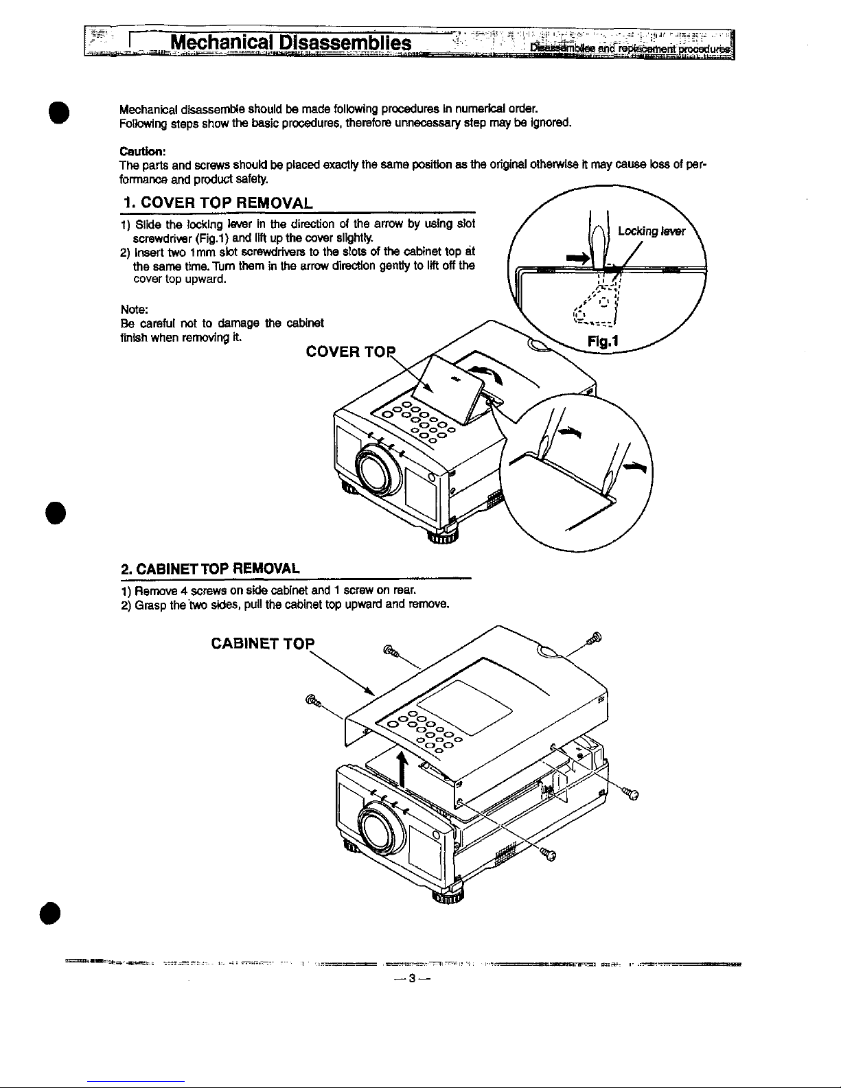
1.
COVER
TOP
REMOVAL
1)
Siide
the
tocking
iever
in
the
direction
of
the
arrow
by
using
s!ot
screwdriver
(Fig.t)
and
ifft
up
the
cover
siight!y-
2)
insert
two
'tmm
stot
screwdrivers
to
the
stots
of
the
cabinet
top
at
the
same
time.
Thm
them
in
the
arrow
direction
gentty
to
lift
off
the
cover
top
upward.
Note:
Be
carefui
not
to
damage
the
cabinet
finish
when
removing
it.
COVER
TOP
2.
CAB!NETTOP
REMOVAL
1)
Remove 4 screws
on
side
cabinet
and 1 screw
on
rear.
2)
Grasp
the
two
stdes,
puii
the
cabinet
top
upward
and
remove.
CABINET
TOP
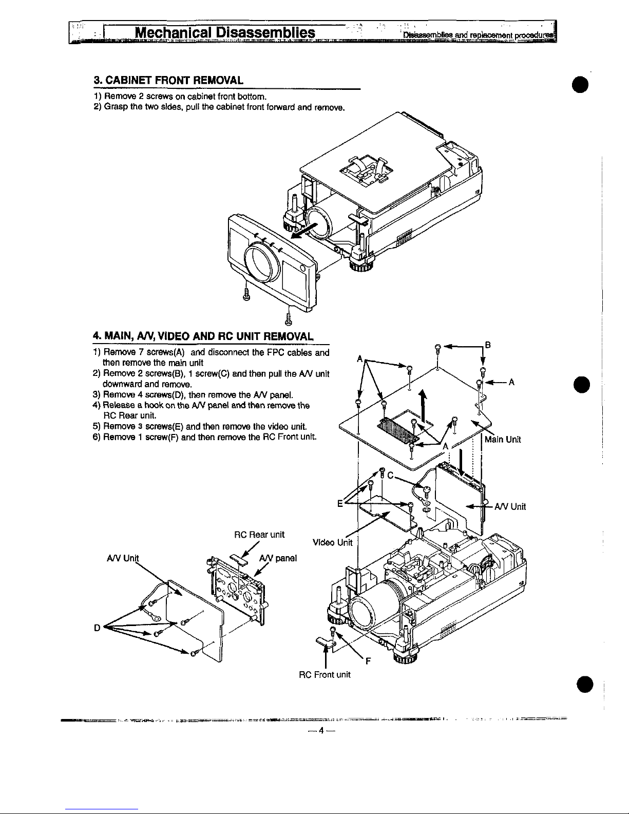
3.
CABINET
FRONT
REMOVAL
1)
Remove 2 screws
on
cabinet
front
bottom.
2)
Grasp
the
two
stdes.
putt
the
cabinet
front
forward
and
remove.
RC
Front
unit
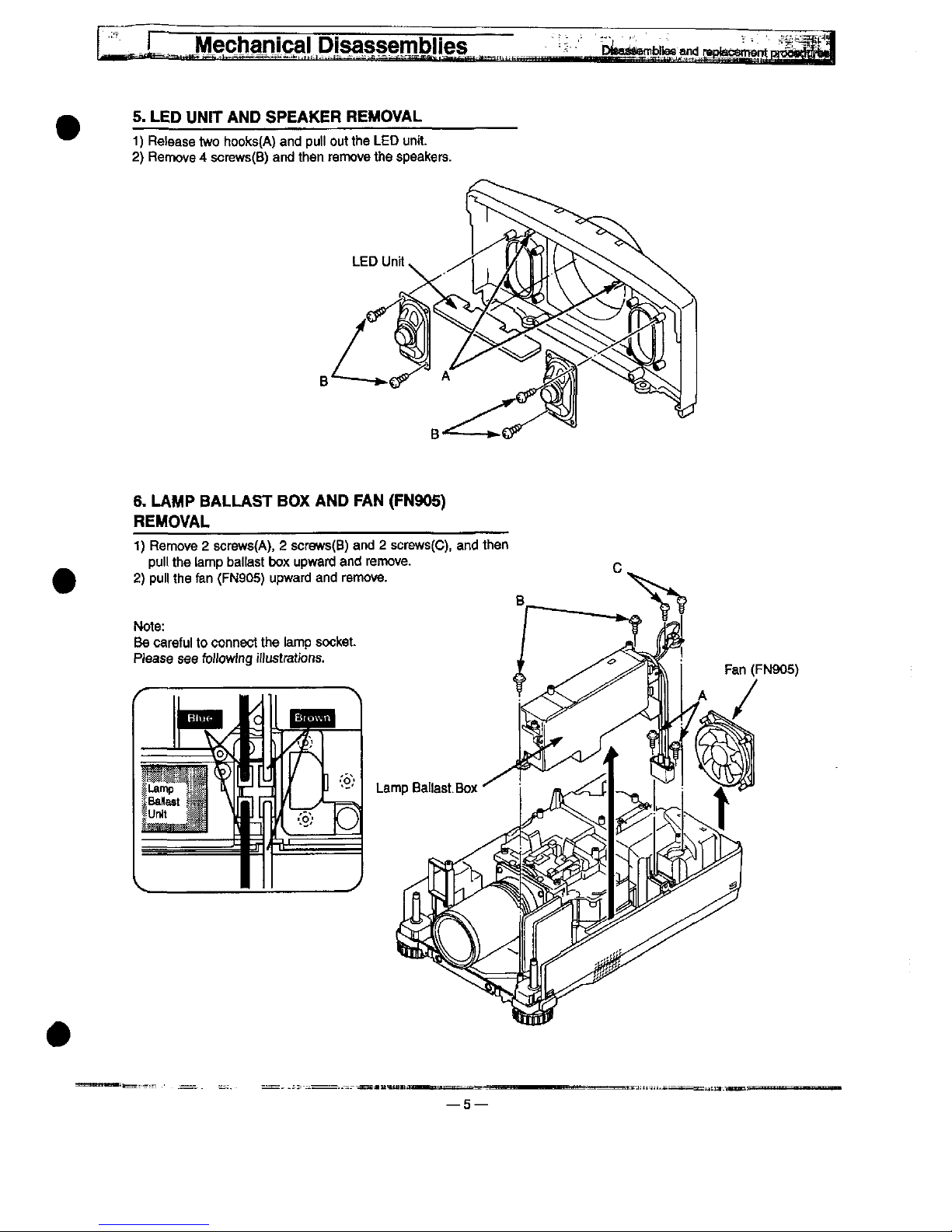
5.
LED
UN!T
AND
SPEAKER
REMOVAL
1)
Retease
two
hooks(A)
and
pu))
out
the
LED
unit.
2)
Remove 4 screws(B)
and
then
remove
the
speakers.
6.
LAMP
BALLAST
BOX
AND
FAN
(FN905)
REMOVAL
1)
Remove 2 screws(A), 2 screws(B)
and 2 screws(C),
and
then
pu)!
the
tamp
ba)!ast
box
upward
and
remove.
2)
pu))
the
fan
(FN905)
upward
and
remove.
—5—
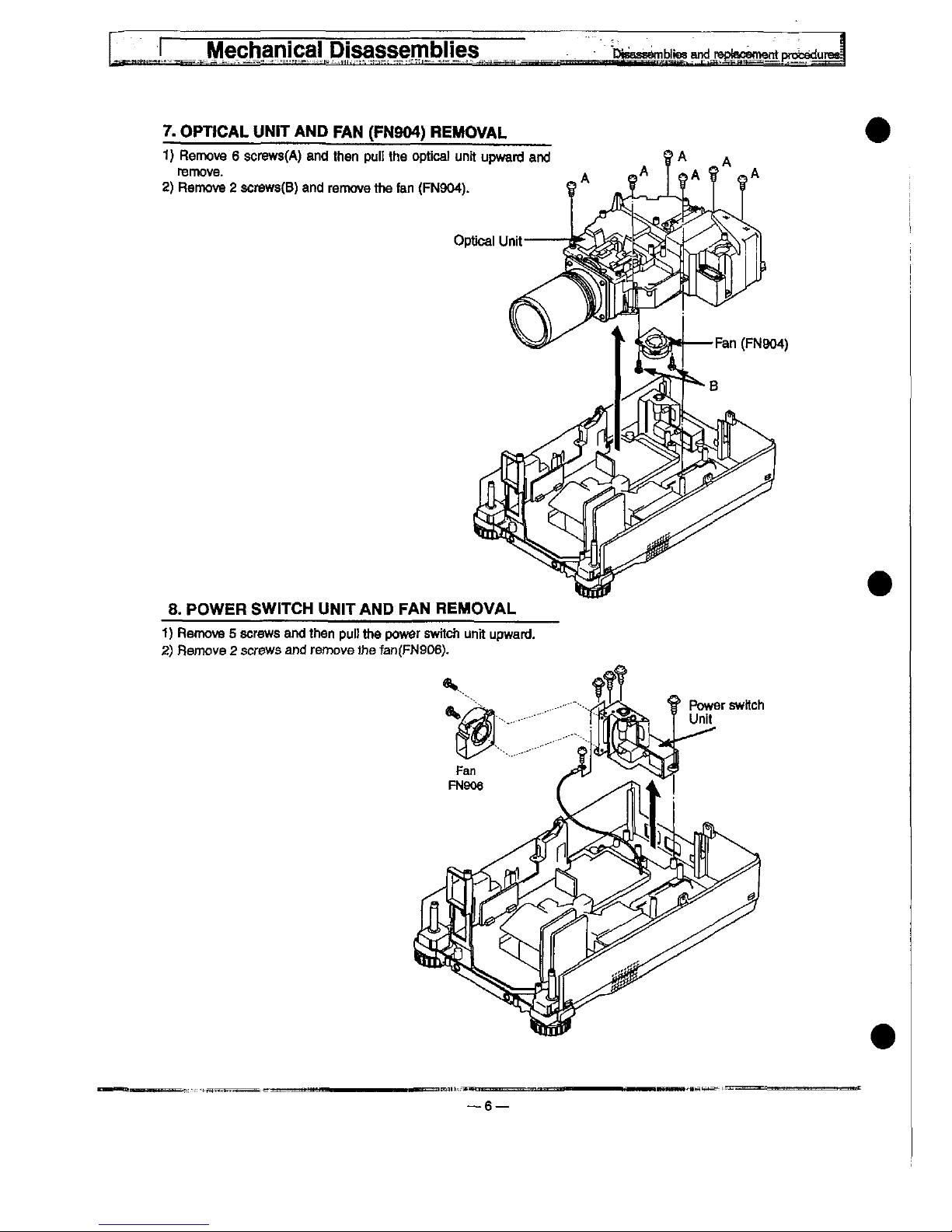
7.
OPDCAL
UN!T
AND
FAN
(FN904)
REMOVAL
f)
Remove 6 screws(A)
and
then
pu!!
the
optica)
unit
upward
and
remove.
2)
Remove 2 screws(B)
and
remove
the
fan
(FN904).
8.
POWER
SW!TCH
UN)TAND
FAN
REMOVAL
1)
Remove 5 screws
and
then
pu)!
the
power
switch
unit
upward.
2)
Remove 2 screws
and
remove
the
fan(FN906).
6—
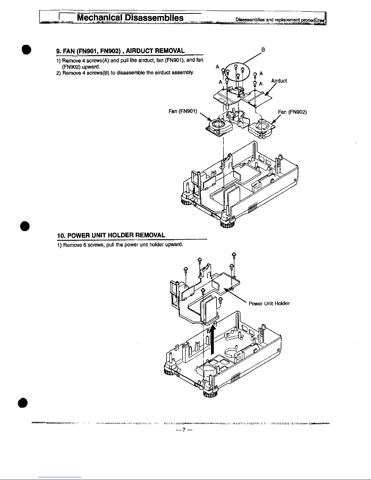
9.
FAN
(FN901,
PN902),
A!RDUCT
REMOVAL
-))
Remove 4 screws(A)
and
pu)t
the
airduct,
fan
(FN901).
and
fan
(FN902)
upward.
2)
Remove 4 screws(B)
to
dtsassembte
the
airduct
assemMy.
Fan
(FN901)
10.
POWER
UN!T
HOLDER
REMOVAL
1)
Remove 6 screws,
pu)[
the
power
unit
hofder
upward-
Power
Unit
Hokier
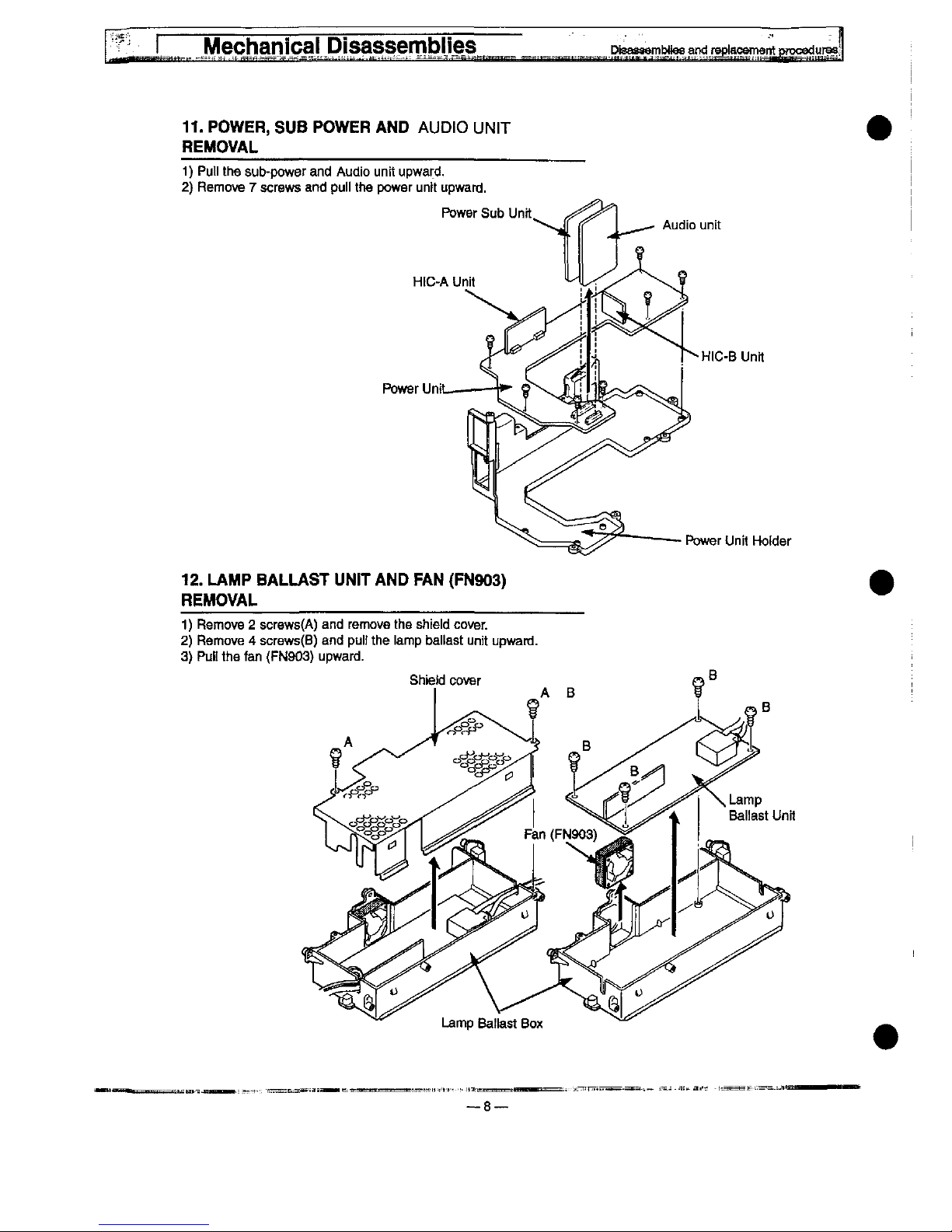
11.
POWER,
SUB
POWER
AND
AUDtO
UN)T
REMOVAL
1)
Put)
the
sub-power
and
Audio
unit
upward.
2)
Remove 7 screws
and
pu!!
the
power
unit
upward.
Audio
unit
HtC-A
Unit
Power
Uni
H!C-B
Unit
Power
Unit
Hotder
12.
LAMP
BALLAST
UN!T
AND
FAN
(FN903)
REMOVAL
1)
Remove 2 screws(A)
and
remove
the
shieid
cover.
2)
Remove 4 screws(B)
and
puif
the
iamp
baitast
unit
upward.
3)
Put!
the
fan
(FN903)
upward.
Lamp
Battast
Box
Remove
the
cabinet,
cabinet
front,
main,
video
and
A/V
unit
fo!kw-
ing
to
steps 2 to 4 of
"Mechanical
Disassembles".
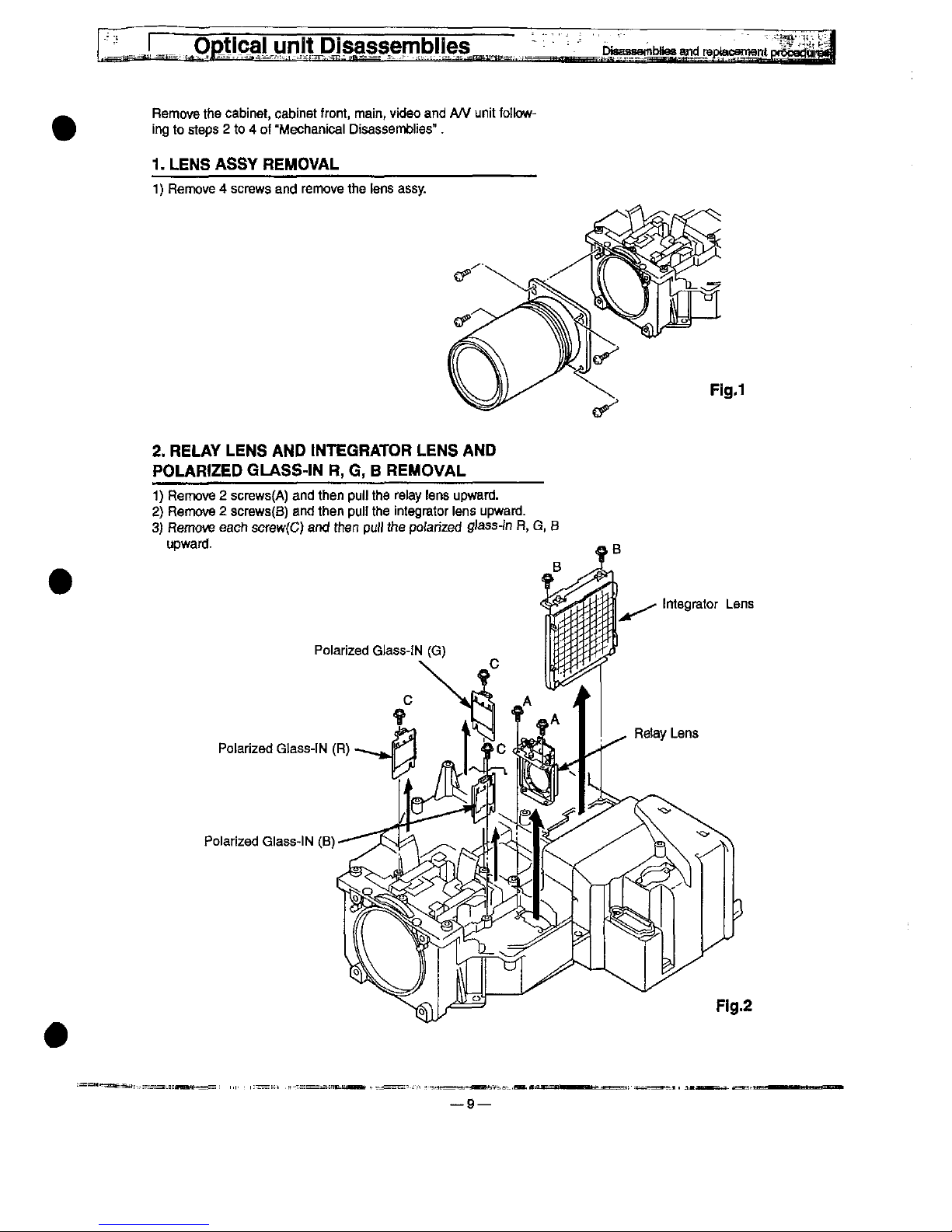
1.
LENS
ASSY
REMOVAL
1)
Remove 4 screws
and
remove
the
tens
assy.
F!g.1
2.
RELAY
LENS
AND
tNTEGRATOR
LENS
AND
POLARIZED
GLASS-)N
R,
G, B REMOVAL
1)
Remove 2 screws(A)
and
then
pufi
the
relay
tens
upward.
2)
Remove 2 screws(B)
and
then
puf!
the
integrator
iens
upward.
3)
Remove
each
screw(C)
and
then
pu!!
the
pofahzed
giass-in
R,
G,
B
upward.
Polarized
Gtass-!N
(G)
Potarized
Gtass-)N
(R)
Poiarized
Giass-iN
(B)
9—
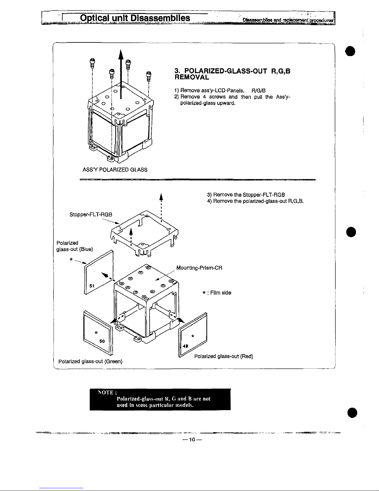
3.
POLAR)ZED-GLASS-OUT
R,G,B
REMOVAL
1)
Remove
ass'y-LCD-Panefs.
R/G/B
2)
Remove 4 screws
and
then
put)
the
Ass'y-
po)arized-g!ass
upward.
ASS'Y
POLAR)ZED
GLASS
3)
Remove
the
Stopper-FLT-RGB
4)
Remove
the
po[arized-g)ass-out
R,G,B.
Potarized
gtass-out
(B)ue)
Mounting-Prfsm-CR
*
:
F!)m
side
Poiarized
g^ass-out
(Green)
Po)arized
g)ass-out
(Red)
Poiarfzed-gt.iss-nut
R, G !tnd B Hre
not
med m 'i!)me
pat'ticutar
inodet',.
10
Qptica)
unJtDJsassembHes
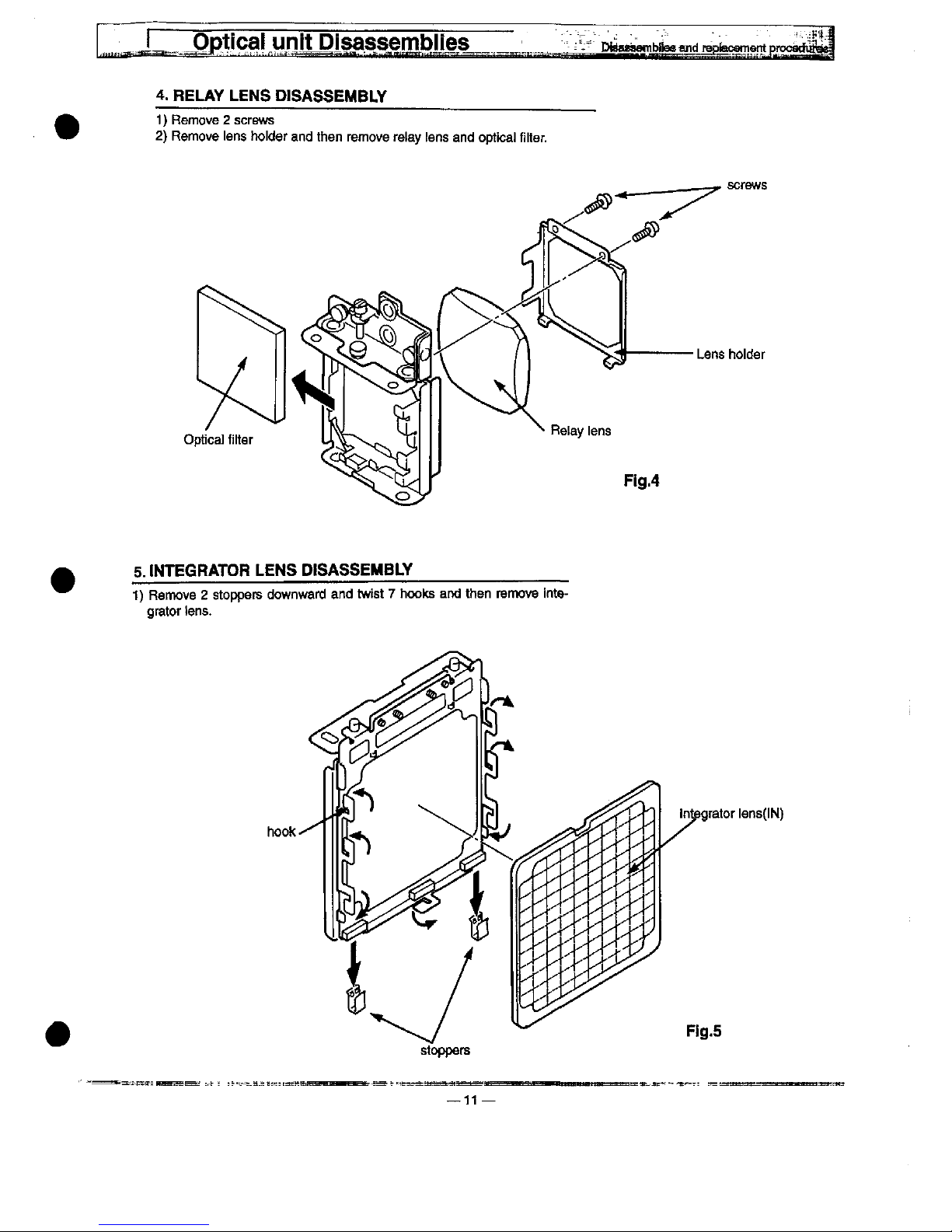
4.
RELAY
LENS
D!SASSEMBLY
1)
Remove 2 screws
2)
Remove
tens
ho)der
and
then
remove
retay
tens
and
optica)
fitter.
screws
Lens
ho)der
5.
tMTEGRATOR
LENS
DISASSEMBLY
1)
Remove 2 stoppers
downward
and
twist 7 hooks
and
then
rerrtovo
inte-
grator
tens.
stoppers
11
integrator
iens(iN)
Pig.5
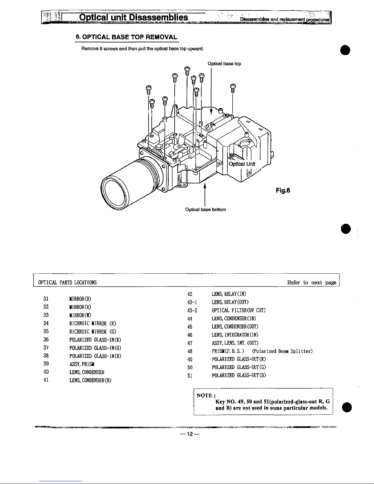
6.
OPT)CAL
BASE
TOP
REMOVAL
Remove 9 screws
and
then
pu^f
the
optica)
base
top
upward.
Optica)
base
top
Fig.6
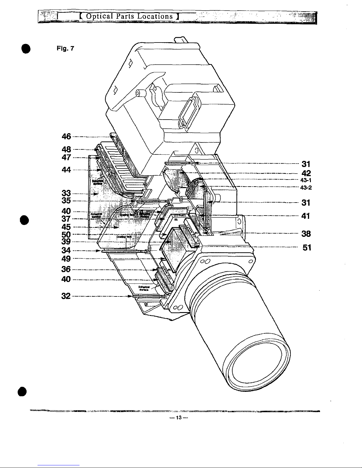
OPTICAL
31
32
33
34
35
36
37
38
39
40
41
PARTS
LOCATIONS
MIRROR(B)
MIRROR(R)
MIRROR(W)
DICHROIC
MIRROR
(R)
DICHROIC
MIRROR
(G)
POLARIZED
GLASS-IN(R)
POLARIZED
GLASS-IN(G)
POLARIZED
GLASS-IN(B)
ASSY.PRISM
LENS,CONDENSER
LENS,CONDENSER(B)
42
43-1
43-2
44
45
46
47
48
49
50
51
Refer
to
next
page
LENS.RELAY(IN)
LENS,RELAY(OUT)
OPTICAL
FILTERS
CUT)
LENS,CONDENSER(IN)
LENS.CONDENSER(OUT)
LENS,
INTEGRATORS)
ASSY,LENS.INT.(OUT)
PRISM(P.B.S.)
(Polarized
Beam
Splitter)
POLARIZED
GLASS-CUT(R)
POLARIZED
GLASS-OUT(G)
POLARIZED
GLASS-OUT(B)
NOTE;
Key
NO.
49,
50
and
5Kpo!arixed-gtass-ont
R,
G
and
B)
are
not
used
in
some
particular
models.
12
13
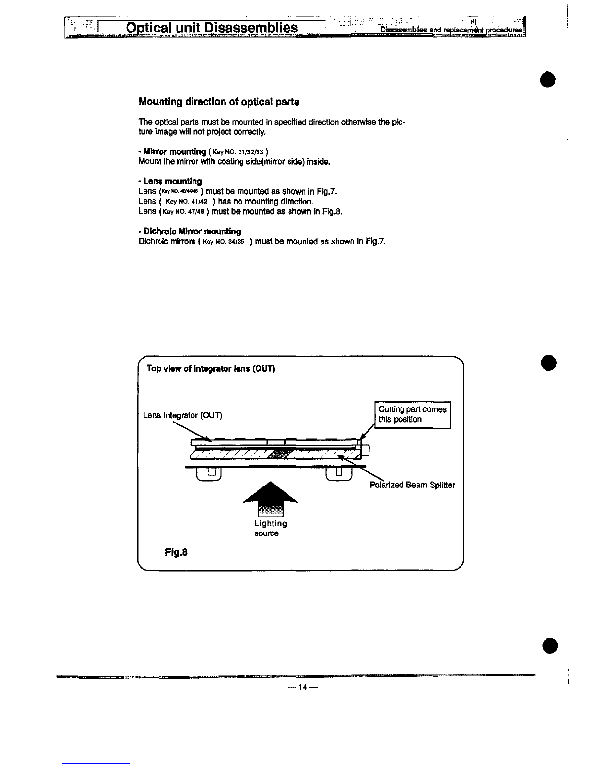
Mounting
direction
of
optica!
parts
The
optica)
parts
must
be
mounted
in
specified
direction
otherwise
the
pic-
ture
imago
wift
not
project
correctiy.
-
Minor
mounting
(Key
No
31/32/33)
Mount
the
mirror
wtth
coating
sid8(mirror
sitte)
inside.
-
Lent
mounting
Lens
(fyMo
w<^)
mu$t
be
mounted
as
shown
in
Ffg.7.
Lens { Key
Mo.
41/42
)
has
no
mounting
direction.
Lens
(Key
no.
47/48)
must
be
mounted
as
shown
in
Fig.8.
-
Dtchro!c
Mtrrof
mounting
Dichroic
mirrors
(Key
no.
34/35
)
must
bo
mounted
as
shown
in
Fig.7.
^^
Top
view
of
integrator
teM
(OUT)
Cutting
part
comes
this
position
Potanzed
Beam
Spittter
Lighting
source
Ftg.8
14—
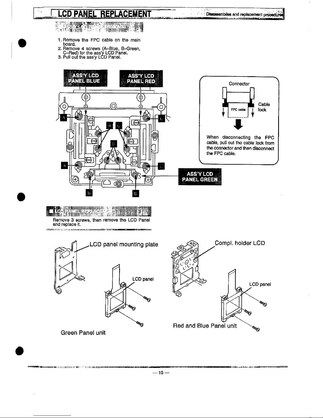
LCD
J'ANE.PLACEMENT
1.
Remove
^e
FPC
cabte
on
the
ma!n
board.
2.
Remove 4 screws
(A=B!ue,
B=Green,
C=Red)
for
the
ass'y
LCD
Pane).
3.
Pu)!
out
the
ass'y
LCD
Pane).
Remove 3 screws,
then
remove
the
LCD
Pane!
and
repfaco
it.
LCD
pane!
mounting
p)ate
Green
Pane)
unit
15—
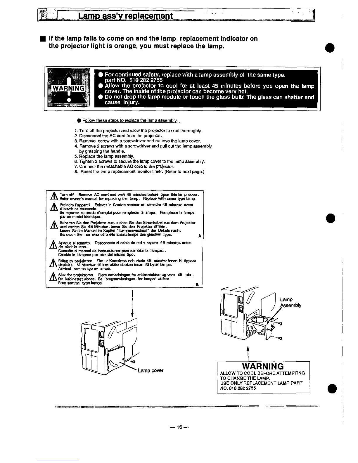
)f
the
tamp
faHs
to
come
on
and
the
tamp
reptacement
indicator
on
the
projector
tight
is
orange,
you
must
replace
the
lamp.
^
For
continued
safety,
rep)ace
with a !amp
assembly
of
the
same
type.
part
NO.
6102822755
^
AHow
the
projector
to
coo!
for
at
ieast
45
minutes
before
you
open
the
tamp
cover.
The
inside
of
the
projector
can
become
very
hot.
^
Do
not
drop
the
tamp
modute
or
touch
the
giass
bu)b!
The
glass
can
shatter
and
cause
injury.
^
Fotbw
these
steps
to
roptace
the
tamp
assembty.
1.
Turn
off
the
projector
and
at)ow
the
projector
to
coof
thoroughty.
2.
Disconnect
the
AC
cord
from
the
projector.
3-
Remove
screw
with a screwdriver
and
remove
the
tamp
cover.
4.
Remove 2 screws
wrth a screwdriver
and
pu!)
out
the
tamp
assemb)y
by
grasping
the
handte.
5.
Repiace
the
)atDp
assemb)y.
6.
Tighten 3 screws
to
secure
the
tamp
cover
to
the
tamp
assemb)y.
7.
Connect
the
detachaMe
AC
cord
to
the
projector.
8.
Reset
the
tamp
repfacement
monitor
timer.
(Refer
to
next
page.)
^
Turn
off.
Remova
AC
cord
and
watt
46
minutes
before
open
this
tamp
cover.
"^
Refer
owner'a
manua)
for
replacing
the
tamp.
Rep)ace
wnh
Mme
type
tamp.
A
EtaindreFapparoi).
Entente
Cordon
aacteur
at
sttandra
46
minutes
avant
/^\
d'ouvrtr
ce
couvefcte.
Sa
mportar
au
fnodg
d'amptoi
pour
ramptacer
ta
ttmpa.
Remptacar
ta
fampe
par
un
modef
identique.
A
Schahen
Se
den
Projaktor
aus,
ziehen
Sie
dss
Stromkabe)
aus
dem
Projektor
/!\
und
warten
Sie
46
Mfnuten.
bavor
Sta
den
Protetctor
<trfner).
LeMn
Sie
im
Manua)
im
KapiM)
"Lampertwachse)''
die
Detaits
nach.
Banutzen
Sie
nur
aine
offiziette
Ersatztampe
dea
giaichen
Typs.
^
A
Apague
wt
aparato.
DMConecte
a)
cabta
da
rad y aapera
45
mintftos
amos
/t\
da
abrirfa
tapa-
Consuha
e)
manuat
do
instfucctonM
para
cambiar
ta
tampara.
Csmbie
)a
)ampafa
por
otra
da)
misfno
tipo.
A
St^ng
BV
projektom.
Dra
ur
Kiontdtten
och
va)m
46
minu^r
innan
Mi
6ppnar
/J\
aftyddet.
Vt
MnvJMf
tit)
!nMtu)c6onsbottan
innan M bytar
)ampa.
Anvand
samma
typ
av
)ampa-
A
S<uk
^r
projektoren.
Fjam
nettedningen
fra
sdkkontakten
og
vent
^5
rrMn..
/!\
far
ktbinettet
abnes-
Se i bnjga'nvisninoen,
far
)ampan
skiftaa.
BfugzatDmetypetampe.
n
Lamp
Assembty
Lamp
cover
WARNtNG
ALLOW
TO
COOL
BEFORE
ATTEMPTING
TO
CHANGE
THE
LAMP.
USE
ONLY
REPLACEMENT
LAMP
PART
N0-6102822755
t6

Lamp
ass'yrep)acement
^
RESET
THE
LAMP
REPLACEMENT
MONITOR
TtMER.
NOTE:
Do
not
reset
the
LAMP
REPLACEMENT
MON)TOR
T)MER,
except
after
the
tamp
is
rep)aced.
1.
Press
the
MENU
BUTTON
and
the
MA!N
MENU
D)SPLAY
diaiog
box
wit)
appear.
2.
Press
the
PO)NT
LEFT/RIGHT
BUTTON(s)
to
se)ect
SETTING
and
press
the
SELECT
BUTTON.
Another
diatog
box
SETDNG
D)SPLAY
wiit
appear.
3.
Press
the
PO)NT
DOWN
BUTTON
and a red
arrow
wit)
appear.
4.
Move
the
arrow
by
pressing
the
PO)NT
UP/DOWN
BUTTOM(s)
to
setoct
Lamp
age
and
then
press
the
SELECT
BUTTON.
When
you
reset
the
tamp
rep!ace
monitor,
lamp
reptace
monitor
reset?"
is
displayed
for
confirmation.
5.
Move
the
arrow
to
Yes
and
then
press
the
SELECT
BUTTON,
"OK?"
is
displayed
for
confirmation.
Move
the
arrow
to
Yes
and
then
press
the
SELECT
BUTTON,
the
tamp
replace
monitor
is
reset.
6.
Move
the
arrow
to
No
and
then
press
the
SELECT
BUTTON.
The
iamp
repface
monitor
is
not
reset.
7.
To
quit
the
MENU,
move
the
arrow
to
Quit
and
then
press
the
SELECT
BUTTON.
MAtN
MENU
DtSPLAY
D)
B)ue
back
Dtsptay
Eng)ish
SETDNG
DISPLAY
Reverse
T/B
Reverse
L/R
)^<B
Spiitwipe
Recommendation
Should
the
air
fitter
become
ctogged
with
dust
particles,
it
wiii
reduce
the
cooiing
fan's
effectiveness
and
may
resuft
in
internal
heat
buiid
up
and
short
iamp
iife.
We
recommend
dean-
ing
the
air
fitter
after
the
projection
iamp
is
replaced.
Refer
to
AiR
FILTER
CARE
AND
CLEANING
on
the
Owner's
Manuai.
OK?
S
^
M
No
)
B^
Power
management
USB
^
Remote
contro!
Mode
1
(
Quit
)
Lamp
rep!ace
monitor
Reset
?
No
NOTE:
Service
Mode
HOW
TO
CHECK
THE
LAMP
tLLUM)NAT!ON
T)ME
P—,
/
!
With
the
projector
in
operating
mode.
press
and
ho!d
the
POINT
UP
button
for
20
seconds,
service
mode
disptay
wit!
appear
on
the
screen.
!
tiiumination
time^Data
Va!ue
Examp)e
)iiumination
time
is
13
hours.--""
!
Press
the
"POWER
ON
OFF"
button
to
qu!tthe
service
mode.
\
Lamp
JXuminatton
titne
Data
no.
Data
^
[0^]
[^
Data
Va)ue
.^'
17
SAFETY
!NSTRUCT)ONS
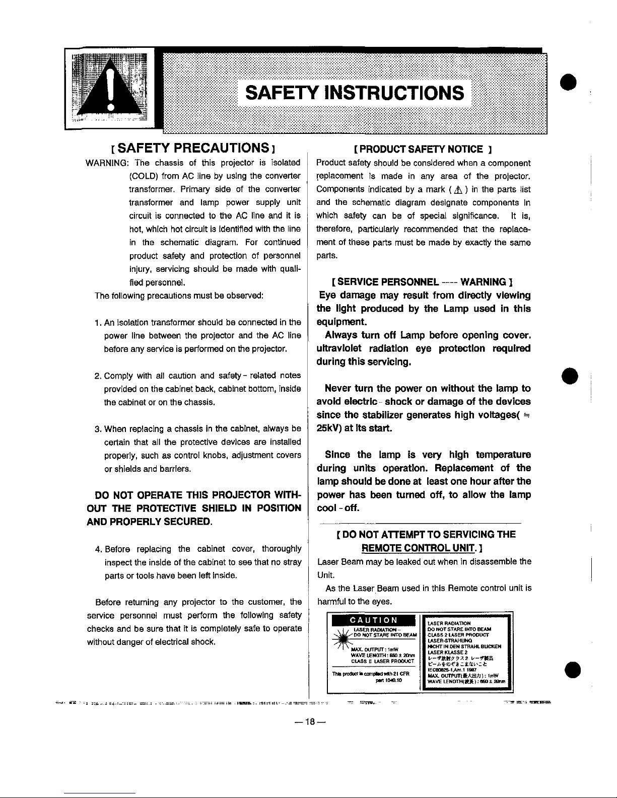
^
SAFETY
PRECAUT!ONS]
WARNING:
The
chassis
of
this
projector
is
isolated
(COLD)
from
AC
line
by
using
the
converter
transformer.
Primary
side
of
the
converter
transformer
and
iamp
power
supply
unit
circuit
is
connected
to
the
AC
iine
and
it
is
hot,
which
hot
circuit
is
identified
with
the
iine
in
the
schematic
diagram.
For
continued
product
safety
and
protection
of
personnel
injury,
servicing
shouid
be
made
with
qua)i-
fied
personnel
The
foiiowing
precautions
must
bo
observed:
1.
An
isotatfon
transformer
shoutd
be
connected
in
the
power
iine
between
the
projector
and
the
AC
iine
before
any
service
is
performed
on
the
projector.
2.
Comp)y
with
ai)
caution
and
safety-
rotated
notes
provided
on
the
cabinet
back,
cabinet
bottom,
inside
the
cabinet
or
on
the
chassis.
3.
When
rep)acing a chassis
in
the
cabinet,
atways
be
certain
that
aii
the
protective
devices
are
installed
properiy,
such
as
control
knobs,
adjustment
covers
or
shields
and
barriers.
DO
NOT
OPERATE
TH)S
PROJECTOR
WtTH-
OUT
THE
PROTECTtVE
SHIELD
)N
POS)T)ON
AND
PROPERLY
SECURED.
4.
Before
replacing
the
cabinet
cover,
thoroughiy
inspect
the
inside
of
the
cabinet
to
see
that
no
stray
parts
or
toois
have
been
ieft
inside.
Before
returning
any
projector
to
the
customer,
the
service
personne)
must
perform
the
following
safety
checks
and
be
sure
that
it
is
compfeteiy
safe
to
operate
without
danger
of
eioctricai
shock.
[PRODUCT
SAFETY
NOT)CE
J
Product
safety
shou)d
be
considered
when a component
replacement
is
made
in
any
area
of
the
projector.
Components
indicated
by a mark
(A)
in
the
parts
list
and
the
schematic
diagram
designate
components
in
which
safety
can
be
of
speciai
significance,
tt
is,
therefore,
particularly
recommended
that
the
replace-
ment
of
these
parts
must
be
made
by
exactly
the
same
parts.
[
SERV)CE
PERSONNEL
WARN!NG
^
Eye
damage
may
resutt
from
directty
viewing
the
tight
produced
by
the
Lamp
used
in
this
equipment.
Atways
turn
off
Lamp
before
opening
cover.
uttravioiet
radiation
eye
protection
required
during
this
servicing.
Never
turn
the
power
on
without
the
tamp
to
avoid
etectric
shock
or
damage
of
the
devices
since
the
stabilizer
generates
high
voitages(
==
25kV)
at
its
start.
Since
the
iamp
is
very
high
temperature
during
units
operation.
Replacement
of
the
lamp
shou!d
be
done
at
teast
one
hour
after
the
power
has
been
turned
off,
to
a!iow
the
tamp
coot - off.
[
DO
NOT
ATTEMPT
TO
SERViONG
THE
REMOTE
CONTROL
UN)T.
^
Laser
Beam
may
be
ieaked
out
when
in
disassemble
the
Unit.
As
the
Laser
Beam
used
in
this
Remote
control
unit
is
harmful
to
the
eyes.
t
CAUTiON
t
, j ,
LASER
RAMATtOM
-
^^^ M HOT
STARE
'MTO
BEAU
^^
'
! ' MAX.
OUTPUT:
tmW
WAVE
UEMQTH:
BSO ± BCrm
CLASS E LASER
PRODUCT
Thttproduttf
compos
wtthEt
CFR
pMtMO.M
M
MOT
STARE
'MTO
BEAM
CLASS : LASER
PROOUCT
LASER-STRAHUMQ
MtCHT
!N
DCN
STHAHL
BUCKEN
LASER
KLASSE
:
t--^&M^?x2
^-fMa
^-AtO^^t^';^
'ECe0626-<.Am.t
<aa7
MAX.OUTPUTj<bA:fi{Jn:'mW
WAVE
LENQTmtt^) ^ 660 ± ZOMn
18
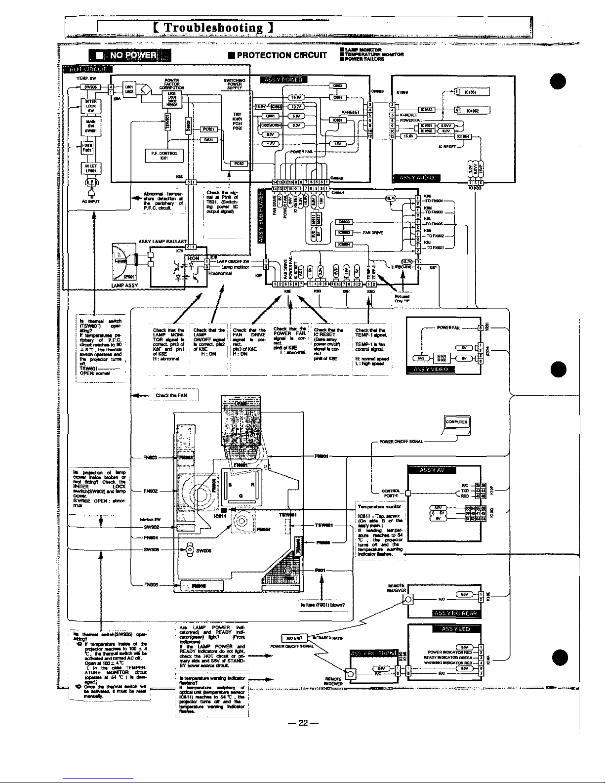
Protections
This
projector
is
equipped
with
the
following
circuit
protections
to
operate
in
safety. H the
abnormality
occurs
inside
the
projector,
tt
wiff
automatical
turn
off
by
operating
one
of
the
lowing
protection
circufts.
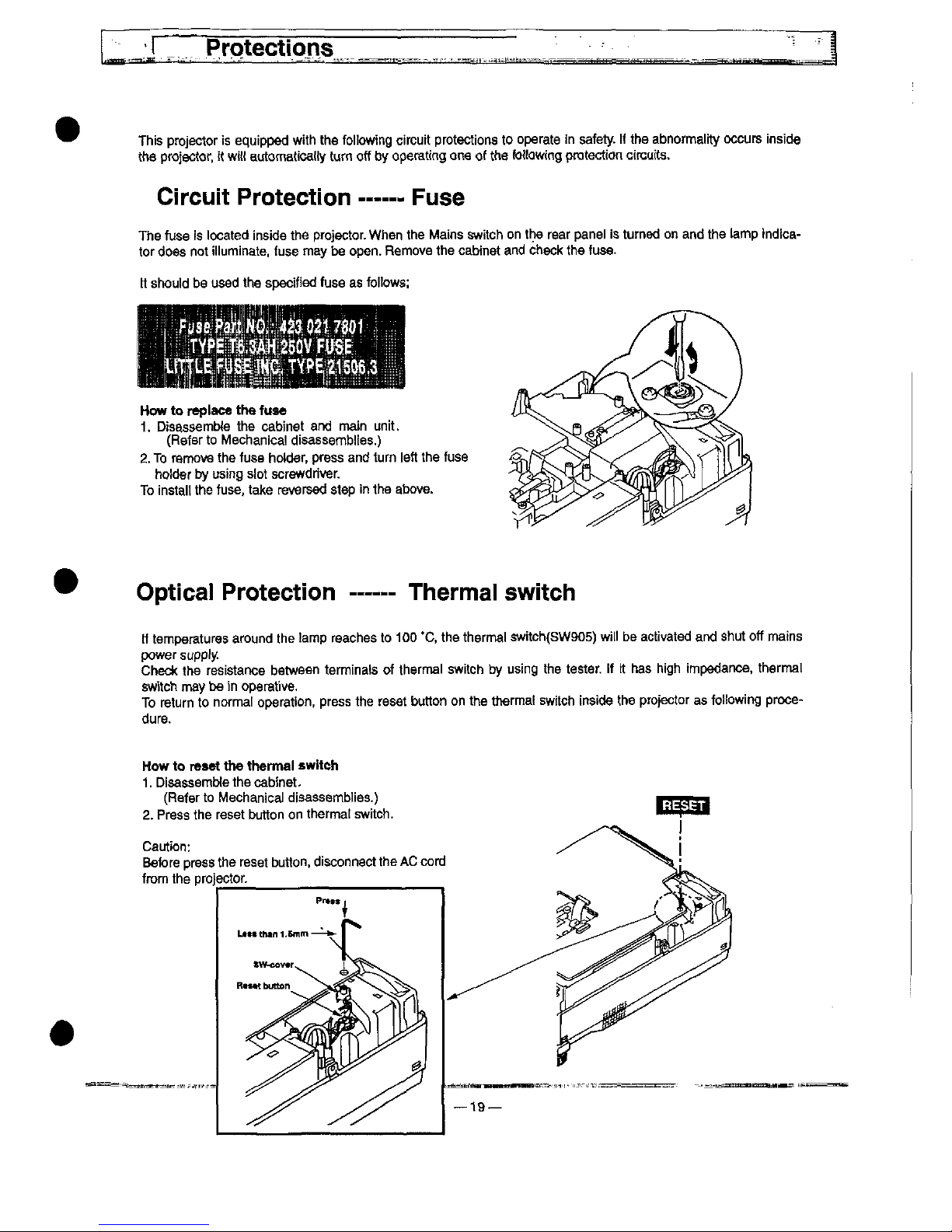
Circuit
Protection
Fuse
The
fuse
!s
located
inside
the
projector.
When
the
Mains
switch
on
the
rear
panei
is
turned
on
and
the
tamp
tndica-
tor
does
not
iiiuminate,
fuse
may
be
open.
Remove
the
cabinet
and
check
the
fuse.
tt
shouid
be
used
the
specified
fuse
as
foiiows:
How
to
reptace
the
fuse
1.
Disassembfe
the
cabinet
and
main
unit.
(Refer
to
Mechanica)
disassembles.)
2.
To
remove
the
fuse
hotder,
press
and
turn
ieft
the
fuse
holder
by
using
siot
screwdriver
To
instait
the
fuse,
take
reversed
step
in
the
above.
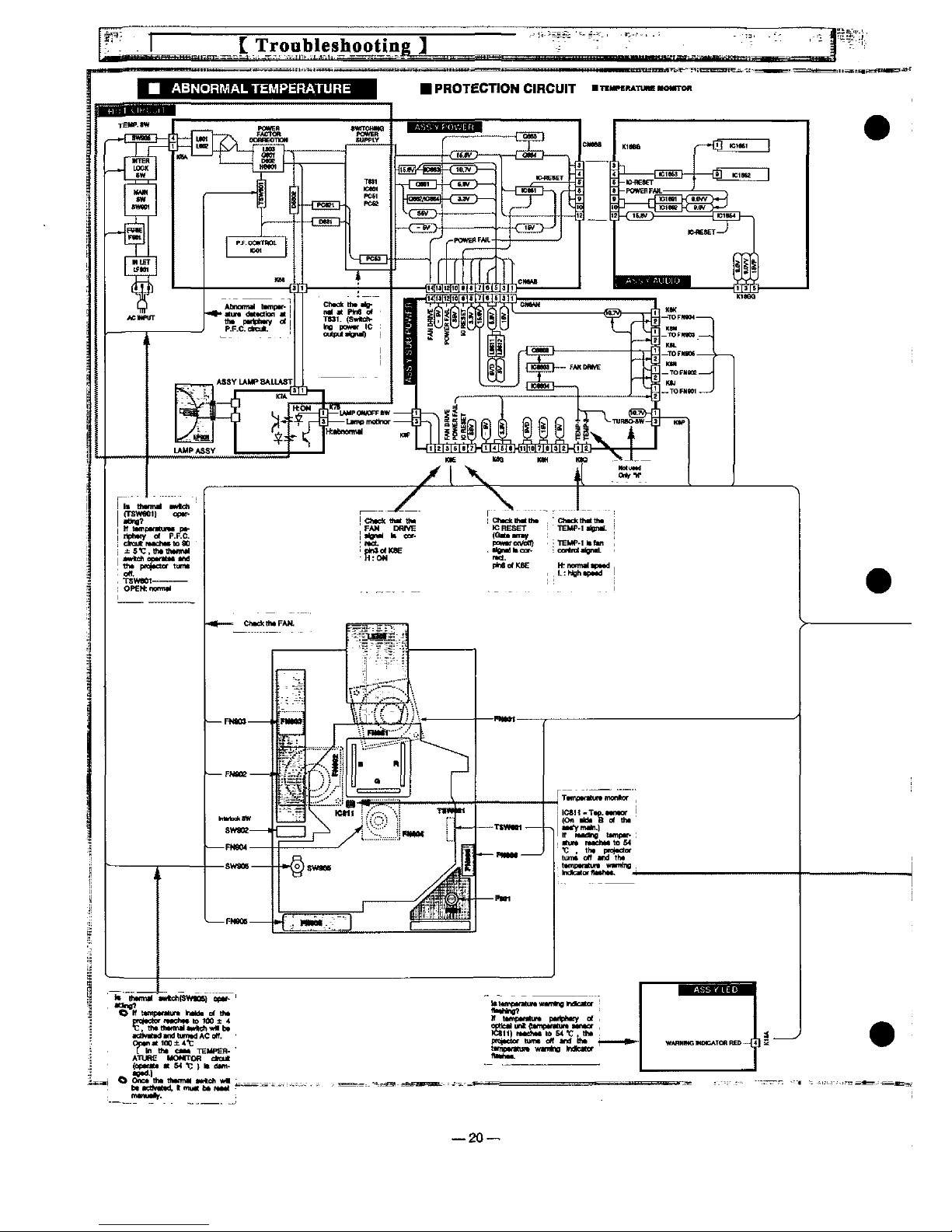
Optica!
Protection
Thermal
switch
tf
temperatures
around
the
tamp
reaches
to
100
*C.
the
thermal
switch(SW905)
wii)
be
activated
and
shut
off
mains
power
supply
Check
the
resistartce
between
terminats
of
thermal
switch
by
using
the
tester,
ft
tt
has
high
impedance,
thermal
switch
may
be
in
operative.
To
return
to
normal
operation,
press
the
reset
button
on
the
thermat
switch
inside
the
projector
as
fo)!owing
proce-
dure.
How
to
re&et
the
therma)
swttch
1.
DisassemMe
the
cabinet.
(Refer
to
Mechanical
disassemblies.)
2.
Press
the
reset
button
on
thermat
switch.
Caution:
Before
press
the
reset
button,
disconnect
the
AC
cord
from
the
projector
____
ATUREHOMfTOR
ctcu*
(e^MM
ft M T ) "
d*m.
<e*^)
0
One*
th*
thtfmtt
t<f0e^
w*
)MMtMHd.<'"uttb<tfttt<
—21
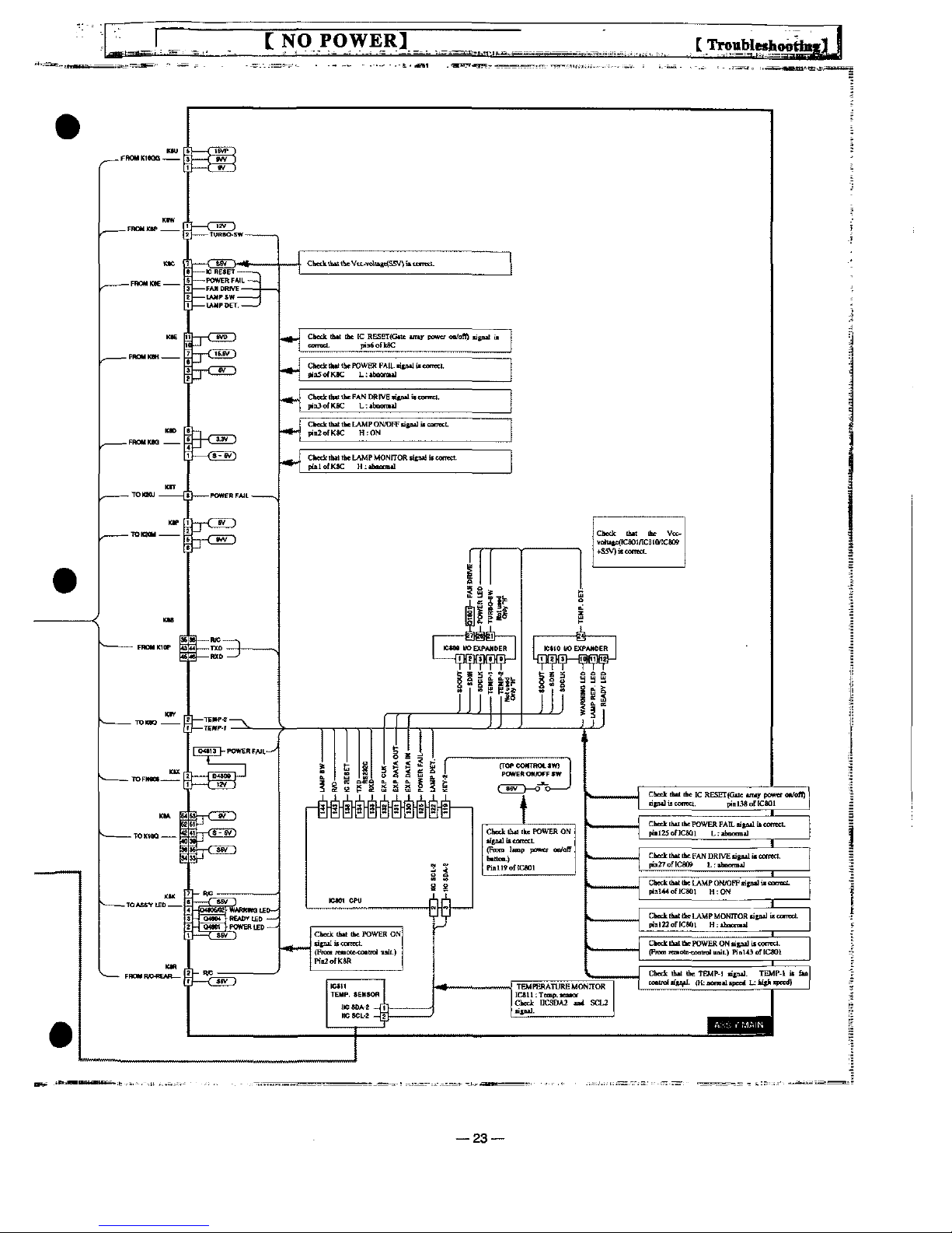
[
NO
POWERJ
23
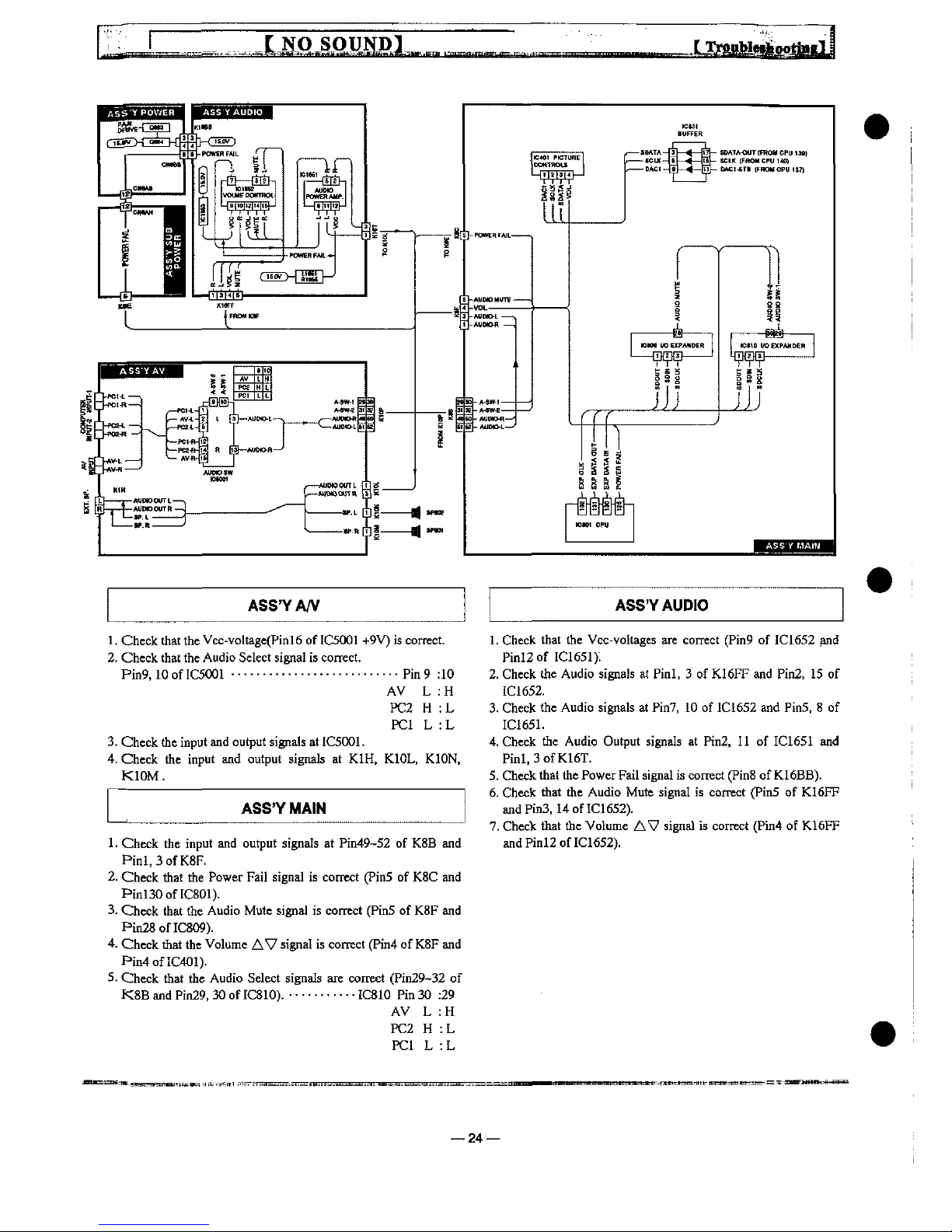
ASS'YA/V
ASS'YAUD!0
1.
Check
that
the
Vcc-vo)tage(Pinl6
of
IC5001
+9V)
is
comet.
2.
Check
that
the
Audio
Select
signal
is
correct.
Pin9.10
ofIC5001---------------------------Pin9:10
AV
L:H
PC2H:L
PC1
L:L
3.
Check
the
input
and
output
signals
at
IC5001.
4.
Check
the
input
and
output
signals
at
KIH.
K10L,
K10N.
K10M.
1.
Check
the
input
and
output
signals
at
Pin49-52
of
K88
and
Pinl,3ofK8F.
2.
Check
that
the
Power
Fai)
signa)
is
correct
(Pin5
of
K8C
and
Pinl30ofIC801).
3-
Check
that
the
Audio
Mute
signa)
is
correct
(Pin5
of
K8F
and
Pm28ofIC809).
4.
Check
that
the
Volume
AV
signal
is
correct
(Pin4
of
K8F
and
F'in4ofIC401).
5.
Check
that
the
Audio
Select
signals
are
correct
(Pin29-32
of
K8B
and
Pin29.
30
of
IC810).
.-.......--
IC810
Pin
30
:29
AV
L:H
PC2H:L
PC1
L:L
1.
Check
that
the
Vcc-voftages
are
correct
(Pin9
of
IC1652
and
Pinl2of
IC1651).
2.
Check
the
Audio
signa!s
at
Pinl. 3 of
K16FF
and
Pin2.
15
of
IC1652.
3.
Check
the
Audio
signals
at
Pin7.
10
of
IC1652
and
Pin5, 8 of
IC1651.
4.
Check
the
Audio
Output
signals
at
Pin2,
11
of
IC1651
and
Pinl,3ofK16T.
5.
Check
that
the
Power
Fait
signal
is
correct
(Pin8
of
K16BB).
6.
Check
that
the
Audio
Mute
signal
is
correct
(Pin5
of
K16FF
andPinS,
14
of
IC1652).
7.
Check
that
the
Volume
AV
signa)
is
correct
(Pin4
of
K16FF
and
Pinl2of
IC1652).
24—
 Loading...