

SANYO PLC-XF45 Service Manual
FILE NO.
SERVICE MANUAL
REFERENCE NO. SM5110433
PRODUCT CODE :
PLC-XF45 MW8A 1 122 15100
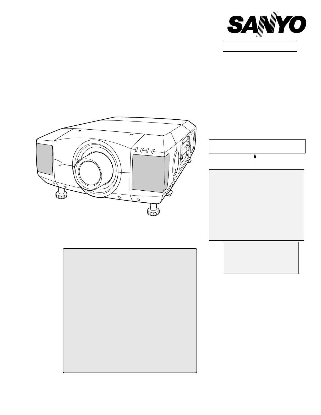
Multimedia Projector
Give complete “CHASSIS NO." for
parts order or servicing, it is shown on
the rating sheet on the cabinet of the
Projector.
Chassis No. MW8-XF4500
NOTE: Match the Chassis No. on the rating
sheet on the cabinet with the
Chassis No. in the Service Manual.
If the Original Version Service
Manual Chassis No. does not
match the unites, additional
Service Literature is required. You
must refer to “Notices” to the
Original Service Manual prior to
servicing the unit.
MODELNO. PLC-XF45
U.S.A., Canada, Europe, Asia, Africa, M.E., U.K.
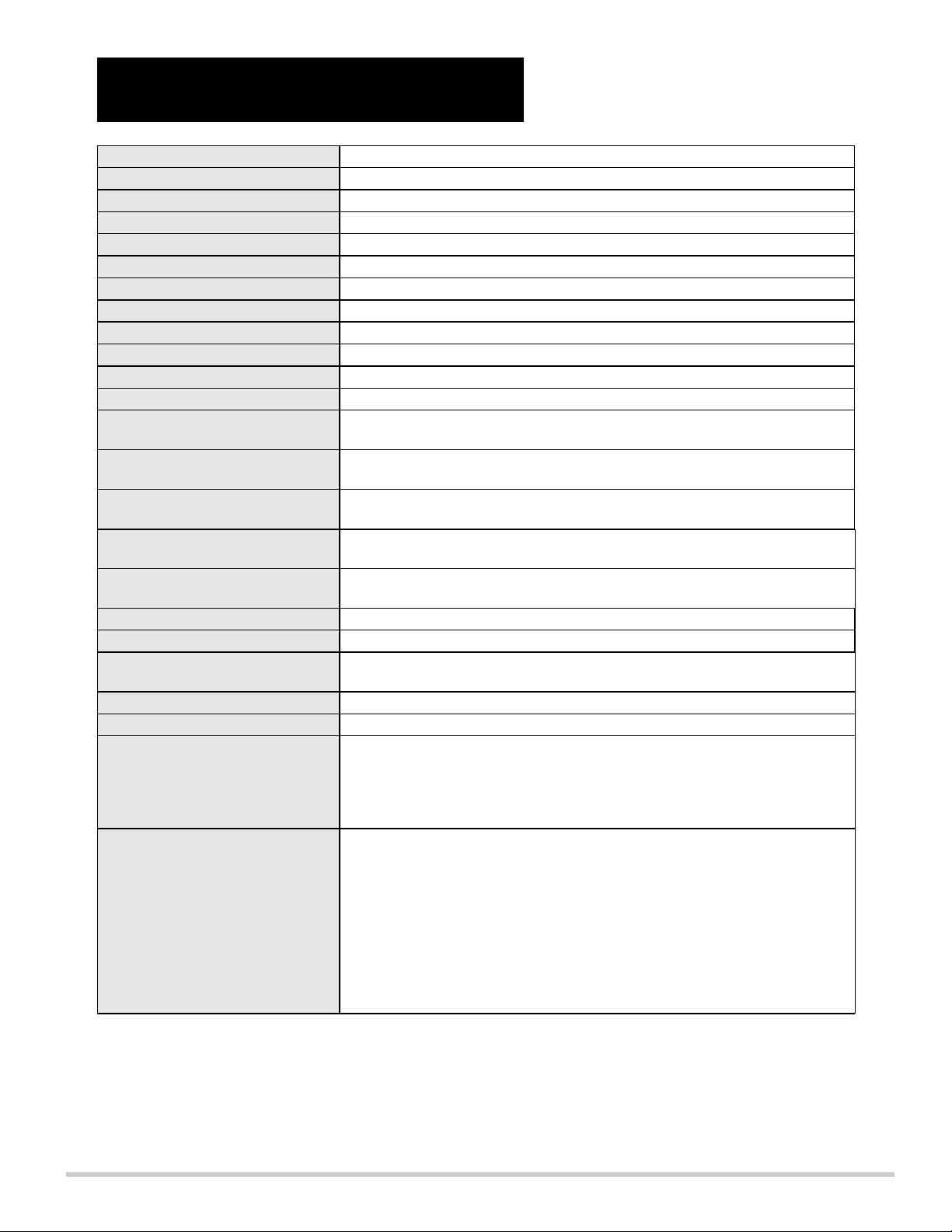
CONTENTS ;
Specifications 2
Safety Instructions 3
Protections 4
Ass'y lamp replacement 6
Mechanical disassemblies 10
Optical unit disassemblies 15
Troubleshooting 26
Waveforms 40
Electrical adjustments 42
Optical adjustments 49
CPU input/output port functions 59
The cautions in schematic diagrams 63
Unit PFC, Unit lamp ballast and IC block diagrams 65
Parts list 70
Cabinet, Chassis and Optical parts list 78
Electrical parts list 79
Schematic diagrams S1~S11
Block diagrams B1~B2
PWB parts location diagrams P1~P6
(Projection lens is optional.)
-2-
Owner’s Manual
AC Power Cord
Wireless/Wired Remote Control Transmitter and Batteries
Remote Control Cable
VGA Cable and DVI Cable
MAC/VGAAdapter and DVI/VGA Adapter
3 Types Control Cable (For PS/2, Serial and ADB port)
6 Types Light-Block Sheet (For option lens)
Lens Mounting Parts
Protective Dust Cover
Accessories
1.8" TFTActive Matrix type, 3 panels
Multi-media Projector
81.7 lbs (37 kg)
22.9" x 10" x 30.9" (581 mm x 252 mm x 783 mm)
1024 x 768 dots
2,359,296(1024 x 768 x 3 panels)
PAL, SECAM, NTSC, NTSC4.43, PAL-M and PAL-N
Up, Down, Left and Right
800 TV lines
INT. SP. Stereo (R and L), 3 watt RMS (T.H.D. 10%)
41˚F ~ 95˚F (5˚C ~ 35˚C)
14 ˚F ~ 140 ˚F (-10 ˚C ~ 60 ˚C)
Projector Type
Net Weight
Dimensions
(W x H x D)
Panel Resolution
Number of Pixels
Color System
Scanning Frequency
Horizontal Resolution
Built-in Speakers
Operating Temperature
Storage Temperature
LCD Panel System
250 watt type x 4
Projection Lamp
0˚ to 5.7˚
Feet Adjustment
Power Source : AA, UM3 or R06 Type x 2
Operating Range : 16.4’ (5m) / ±30˚
Dimensions : 2.2” x 1.3” x 7.6” (55mm x 34mm x 192mm)
Net Weight : 0.36 lbs (165 g) (including batteries)
Laser Pointer : Class II Laser
(Max. Output : 1mW / Wave length : 650±20nm)
Remote Control Transmitter
480i, 480p, 575i, 575p, 720p, 1035i, 1080i-50 and 1080i-60
High Definition TV Signal
AC 120 V (12 A Max. Ampere), 50 / 60 Hz
(The U.S.A and Canada)
AC 200 ~ 240 V (7.5 A Max. Ampere), 50 / 60 Hz
(Continental Europe and The U.K.)
Voltage and
Power Consumption
H-sync. 15 ~ 120 KHz, V-sync. 50 ~ 120 Hz
Motorized Lens Shift
DVI-I Terminal (Digital/Analog), RCAType (Audio R and L)
and DIN 8-pin (Control port)
Input 1 Jacks
BNC Type x 5 (R/Pr, G/Y, B/Pb, H/HV and V), RCAType (Audio R and L)
and DIN 8-pin (Control port)
Input 2 Jacks
BNC Type x 2 (VIDEO/Y, C), RCAType (Audio R and L)
and DIN 4-pin (S-Video)
Input 3 Jacks
Serial port in (DB 9), Serial port out (DB 9), USB port,
Audio Monitor out (RCAType R and L) and Wired Remote Jack
Other Jacks
HDB 15-pin Terminal (Analog), RCA Type (Audio R and L)
and DIN 8-pin (Control port)
Input 4 Jacks
● Specifications are subject to change without notice.
● LCD panels are manufactured to the highest possible standards. At least 99.999% of the pixels are
effective, however a tiny fraction of the pixels (0.001% or less) may be ineffective by the characteristics of
the LCD panels.
TECHNICAL
SPECIFICATIONS
-3-
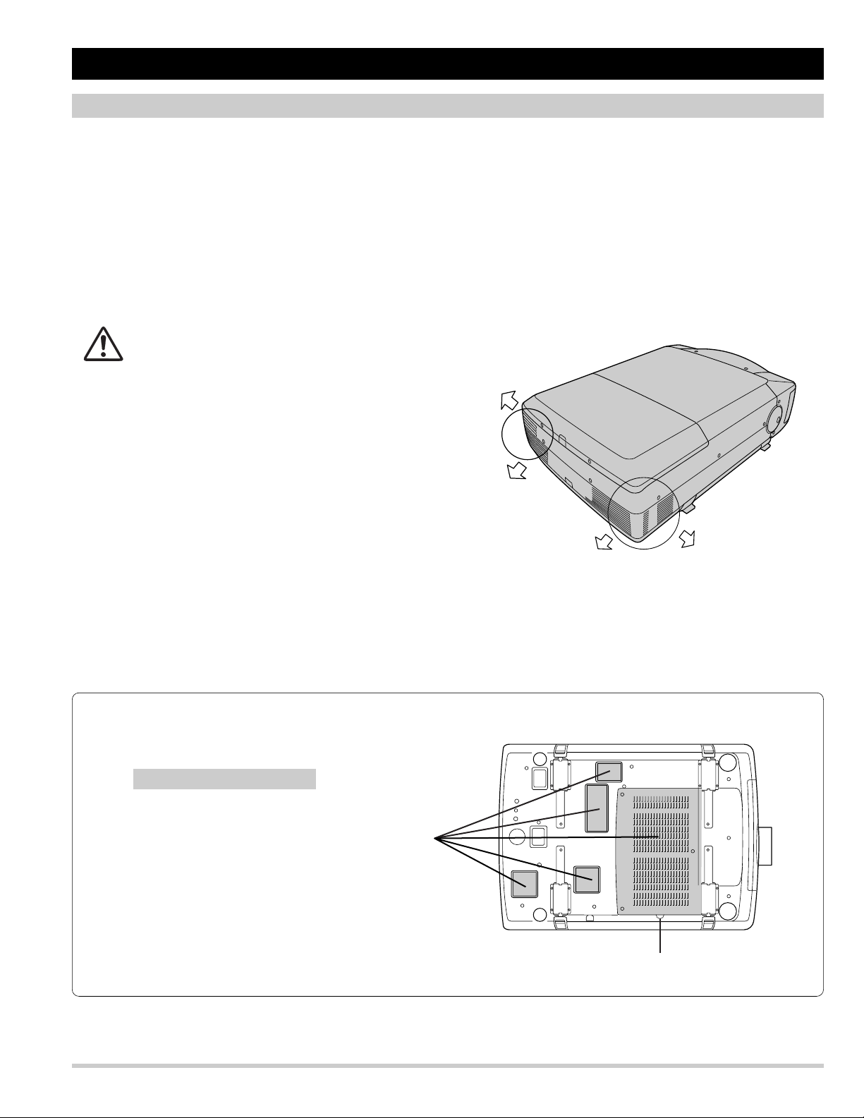
SERVICE PERSONNEL WARNING
Eye damage may result from directly viewing the
light produced by the Lamp used in this equipment.
Always turn off Lamp before opening cover. The
Ultraviolet radiation eye protection is required during
this servicing.
Never turn the power on without the lamp to avoid
electric-shock or damage of the devices since the
stabilizer generates high voltages (20~25kV) at its
starts.
Since the lamp is very high temperature during units
operation. Replacement of the lamp should be done
at least 45 minutes after the power has been turned
off, to allow the lamp cool-off.
WARNING:
The chassis of this projector is isolated (COLD) from
AC line by using the converter transformer. Primary
side of the converter and lamp power supply unit circuit is connected to the AC line and it is hot, which hot
circuit is identified with the line ( ) in the
schematic diagram. For continued product safety and
protection of personnel injury, servicing should be
made with qualified personnel.
The following precautions must be observed.
SAFETY PRECAUTIONS
1: An isolation transformer should be connected in the
power line between the projector and the AC line
before any service is performed on the projector.
2: Comply with all caution and safety-related notes
provided on the cabinet back, cabinet bottom, inside
the cabinet or on the chassis.
3: When replacing a chassis in the cabinet, always be
certain that all the protective devices are installed
properly, such as, control knobs, adjustment covers or shields, barriers, etc.
DO NOT OPERATE THIS PROJECTOR WITHOUT
THE PROTECTIVE SHIELD IN POSITION AND
PROPERLY SECURED.
4: Before replacing the cabinet cover, thoroughly
inspect the inside of the cabinet to see that no stray
parts or tools have been left inside.
Before returning any projector to the customer, the
service personnel must be sure it is completely safe
to operate without danger of electric shock.
PRODUCT SAFETY NOTICE
Product safety should be considered when a component replacement is made in any area of the projector. Components indicated by mark in the parts
list and the schematic diagram designate components in which safety can be of special significance.
It is, therefore, particularly recommended that the
replacement of the parts must be made by exactly
the same parts.
DO NOT ATTEMPT TO SERVICING THE
REMOTE CONTROL UNIT.
Laser Beam may be leaked out when in disassemble the Unit. As the Laser Beam used in this
Remote control unit is harmful to the eyes.
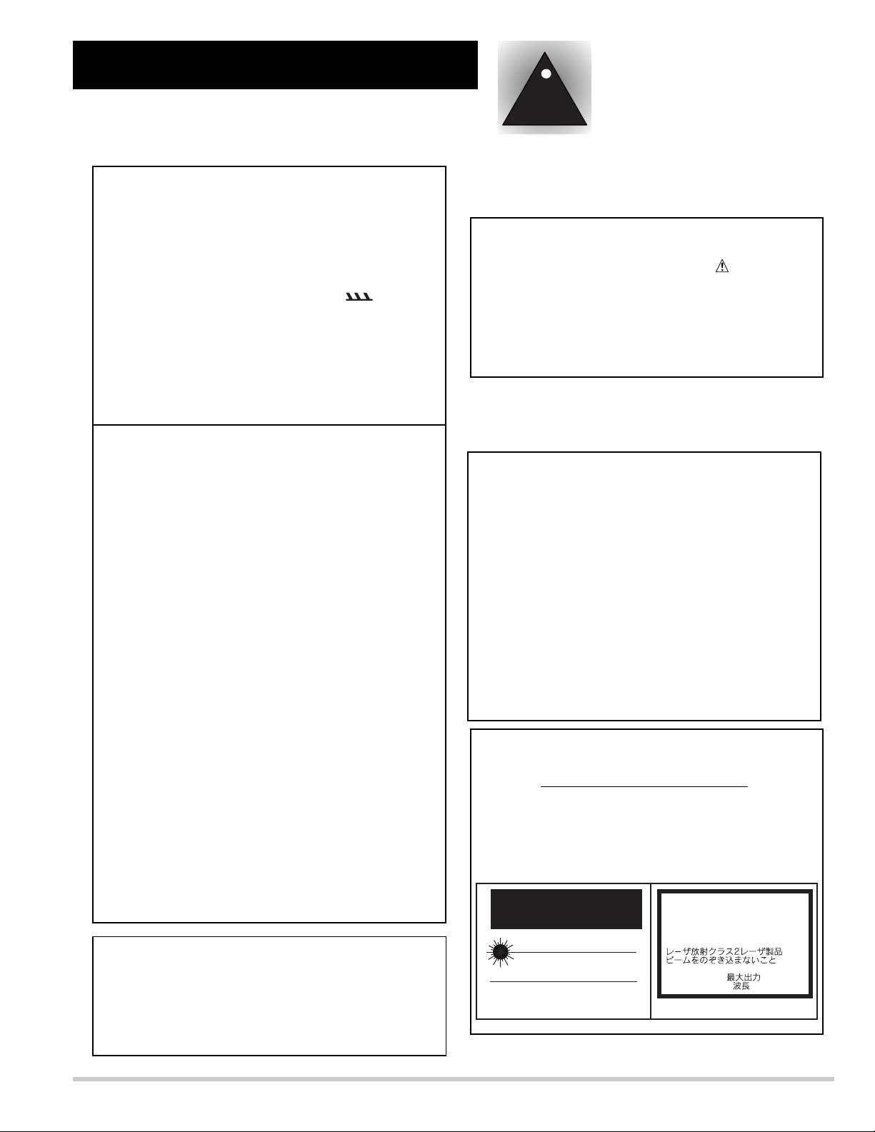
LASER RADIATION
DO NOT STARE INTO BEAM
MAX. OUTPUT: 1mW
WAVE LENGTH: 650±20nm
CLASS II LASER PRODUCT
This product is complied with 21 CFR
part 1040.10
CAUTION
LASER RADIATION
DO NOT STARE INTO BEAM
CLASS 2 LASER PRODUCT
LASER-STRAHLING
NICHT IN DEN STRAHL BLICKEN
LASER KLASSE 2
IEC60825-1, Am. 1 1997
MAX OUTPUT ( ) : 1 mW
WAVE LENGTH ( ) : 650±20nm
!
Safety Instructions
CAUTION
RISK OF EXPLOSION IF BATTERY IS REPLACED
BY AN INCORRECT TYPE.
DISPOSE OF USED BATTERIES ACCORDING
TO THE INSTRUCTIONS.
-4-
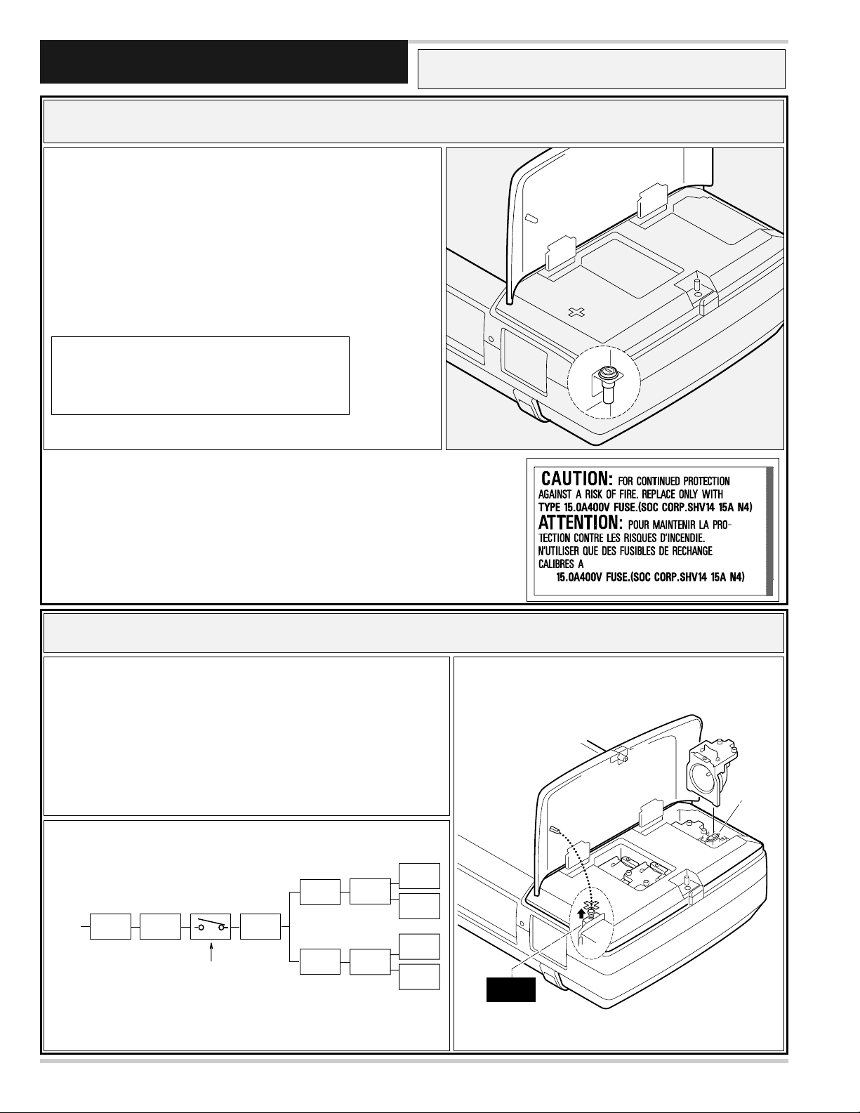
This projector is equipped with the following protections to operate in safety.
Protections
❏ Fuse for circuit protection
The fuse is located in the rear inside a projector. (Refer to figure.) When
either the LAMP indicator or the READY indicator is not illuminated,
fuse may be opened. Check the fuse as following steps.
1. Remove the Cabinet-top following to “Mechanical Disassemblies”.
2. Remove the fuse from fuse holder.
3. Check the resistance of fuse using a tester.
To install the fuse, take reversed step in the above.
It should be used the specified fuse as follows;
Fuse Part No.: 423 028 4209
TYPE 15.0A400V FUSE
SOC CORP. SHV14 15A N4
■ The Lamp circuit (the lamp and the electrode of the lamp socket)of this
projector is not insulated from AC line, and it is "HOT." Therefore,
when replacing lamp assembly, an electric shock may be received.
However, the interlock switch (SW902) is designed so that it may protect
from the accident.
■ This switch(SW902) insulates a lamp circuit from AC line, when cover -
top is opened. (The lamp circuit changes to "COLD.")
❏ Protection equipment for users Electric shock protection. (Interlock switch)
The label of the right figure sticks near the Fuse.
Lamp 1
Lamp 2
Lamp 3
Lamp 4
AC INPUT
Fuse
F901
Main sw
SW901
Interlock SW
SW902
Ass'y
Power
P.F.C.
P.F.C.
Lamp
ballast
Lamp
ballast
Interlock
switch
Cover top
Lamp socket
-5-
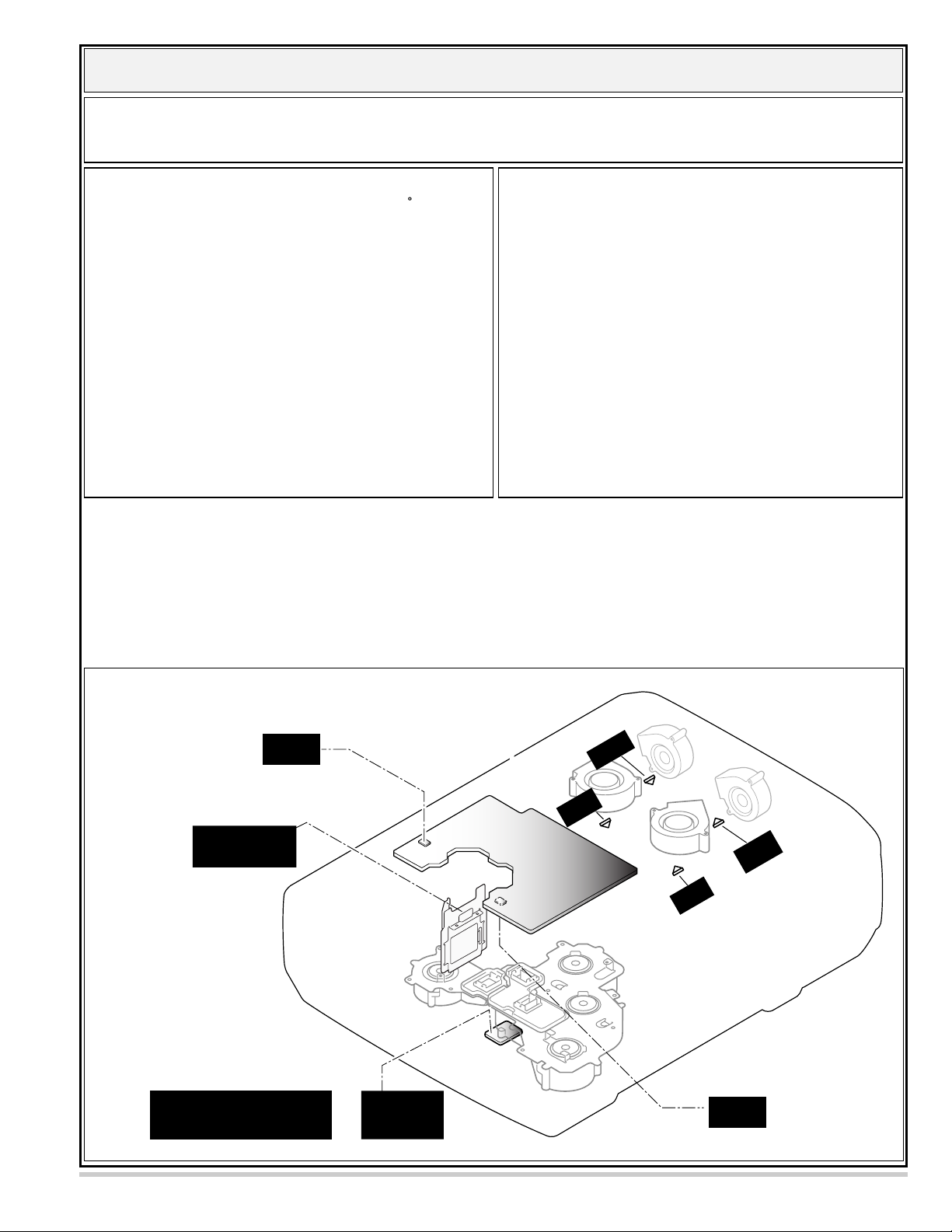
❏ Overheating Protection -- The temperature monitor system --
----- The temperature monitor -1: -----
■ To control the driving power of the cooling fans.
The CPU checks the temperature and atmospheric pressure
inside a projector. It checks a temperature using temperature
sensor-IC5801, IC2541 and it checks an atmospheric pressure
using pressure sensor-IC886.
The CPU controls the driving power of the cooling fans so the
temperature inside the projector is maintained to normal temperature.
■ To shut down the projector.
The CPU checks temperature of Blue polarization glass
(PTH901) and inhalation air(IC5801). If each part temperature reaches to abnormal temperature, the CPU will turn off a
projector, and will blink TEMPERATURE WARNING indicator at intervals of 0.6 seconds. Cooling fans operate until
temperature returns to normal. Indicator will stop blink, if
temperature returns to normal.
The temperature monitor system is provided to prevents damage of optical components (the LCD panel and polarization
film etc.) inside a projector from overheat. Two protection systems are provided.
Each system operation as follows ;
----- The temperature monitor -2 : -----
(Temperature check of lamps. )
Temperature switches (SW 903~906) are arranged near the
four lamps. T emperature switches will operate, if temperature
reaches 100 degrees.
SW (903~906) ----- It operates at 100 degrees.
(Lamp-1~4)
When temperature switches have operated, lamp ballast units
will be shut down, then a projector will be turned off.
Note.
The CPU does not check operation of temperature switches.
Therefore, when temperature switches have operated and a
projector has shut down, TEMPERATURE-WARNING
indicator does not blink.
Check the following possible causes and wait until stopping the TEMP WARNING indicator flashing.
Possible causes
- Air filter is clogged with dust particles. Remove dust from the air filter by following instruction in the
"Air filter care and cleaning" below.
- Ventilation slots of the projector are blocked. In such an event, reposition the projector so that ventilation
slots are not obstructed.
- Check if projector is used at higher temperature place(Normal operate is 5 to 35°C or 41 to 95°F)
PRESSURE
SENSOR
IC886
PTH901
Temp. Sensor
(Blue polarization glass)
Front side
Temperature sensors
location
A
-Side
Blue polarizer unit
IC5801
Temp. Sensor
(I
nhalation air
906
W
S
100*C
p4
For
p3
For
Lam
Lam
p1
903
W
S
100*C
w
perature s
Tem
are arranged to B
Temp.
SENSOR
IC2541
p2
For
Lam
904
W
S
100*C
itches (SW
ottom
903/904/905/906)
of the optical unit.
905
SW
100*C
For
Lam
Main
B
-Side
)
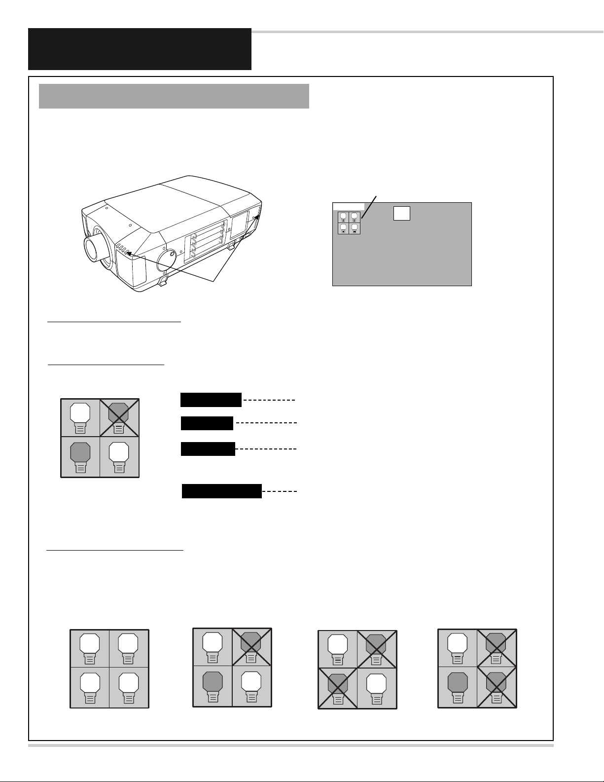
This Projector is equipped with 4 Projection Lamps to ensure brighter image and those lamps are controlled by Lamp
Management Function. Lamp Management Function detects status of all lamps and shows status on screen or on LAMP
REPLACE indicator. This function also automatically controls Lamp Mode when any of lamps is out for end of life or
malfunctions.
Projection Lamp lights normally.
Lamp Replace Indicator
This LAMP REPLACE indicator lights yellow when any of Projection Lamps is nearing its end, and flashes when any of them
becomes out. Check number of lamp on Lamp Status Display and replace lamp.
Yellow Lamp
Dim Lamp
X Mark on Lamp
Red Lamp
LAMP REPLACE
INDICATOR
Projection Lamp is turned off.
Projection Lamp is nearing its end. When image becomes
darker or color becomes unnatural, replace lamp. (LAMP
REPLACE indicator lights yellow.)
(LAMP REPLACE indicator flashes yellow.)
Projection lamp is defective or fails to be turned on. Restart
a projector on, and make sure lamp is on. If this mark still
appears, replace lamp corresponding with number marked X.
LAMP STATUS
DISPLAY
1
4
3
2
Lamp Mode Changeover
Lamp Management Function automatically changes combination of lighting lamp (Lamp Mode) by detecting status of lamp.
When any of 4 lamps becomes out, Lamp Mode is changed over from 4 lamps to 2 lamps. And when any of 2 lamps are out,
a projector operates with 1 lamp. But, in case of combination that the Lamp of 1-4, or 2-3 does not light up, it becomes a 2
lamps mode.
Lamp Mode can be switched to 4 lamps or 2 lamps manually. Refer to SETTING section of Owner's manual
.
1
2 4
3
1
4
3
2
4 LAMP MODE
2 LAMP MODE
(Example)
1
4
3
2
2 LAMP MODE
(Example)
1
3
2
4
1 LAMP MODE
(Example)
Lamp Status Display
Lamp Status Display appears on screen when power switch is on or changed input position (input 1, input 2, Input 3 or input 4).
This shows status of each lamp as; ON, OFF, NEAR END, or OUT. Refer to following for each status.
30
LAMP STATUS
INPUT 1
1
2 4
3
LAMP REPLACEMENT
Before Replacement
-6-
-7-
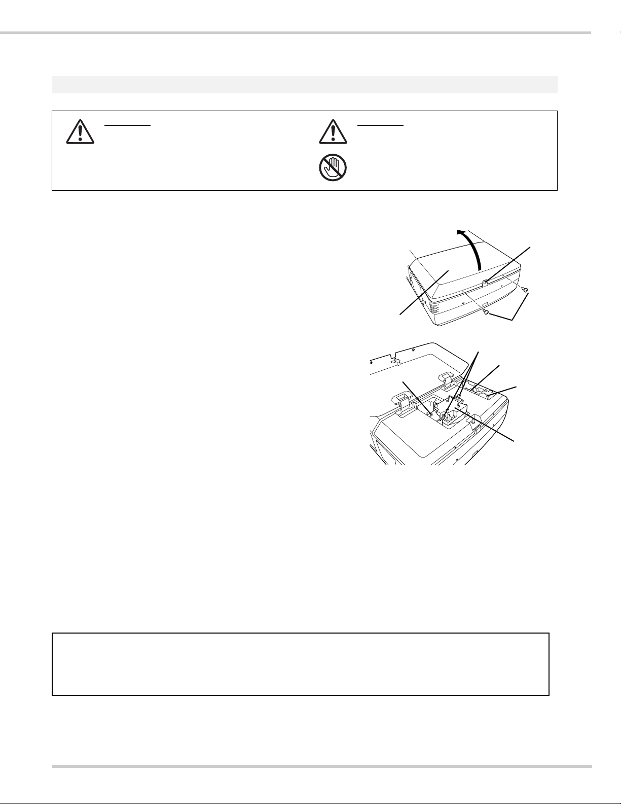
LAMP REPLACEMENT
CAUTION
Do not drop a lamp assembly or touch a glass
bulb! Glass can shatter and may cause injury.
CAUTION
For continued safety, replace with a lamp
assembly of same type.
Allow a projector to cool for at least 45
minutes before you open Lamp Cover. Inside
of a projector can become very hot.
Check number of lamp to be replaced on Lamp Status Display.
Remove two screws on Lamp Cover and press button to open
Lamp Cover. (See right figure.)
1
3
Loosen two screws and pull out Lamp Assembly to be replaced
by grasping handle.
4
Turn off a projector and disconnect AC Power Cord. Allow a
projector to cool down for at least 45 minutes.
2
Replace Lamp Assembly with a new one and tighten two screws.
Make sure Lamp is set properly
6
Follow these steps to replace lamp assembly.
Replace Lamp Cover and tighten two screws.
5
7
8
Connect AC Power Cord to a projector and turn a projector on.
Reset Lamp Replacement Counter. (Refer to section "Lamp
Counter Reset".)
NOTE : Do not reset LAMP REPLACEMENT COUNTER when
lamp is not replaced.
BUTTON
SCREWS
LAMP
COVER
SCREWS
Make sure which number of lamp needs to be
replaced on Lamp Status Display.
Figure shows case of replacing LAMP 2.
LAMP 1
LAMP 2
LAMP 3
LAMP 4
CAUTION :Do not operate a Projector while any of lamps removed.
It may result in malfunctions, fire hazard, or other accidents.
NOTES ON LAMP REPLACEMENT
To maintain quality of picture (better balance of color and brightness in entire screen), we
recommend replacing all 4 lamps at a time.
CAUTION :High pressure lamp may explode if improperly handled.
Refer to lamp replacement instructions.
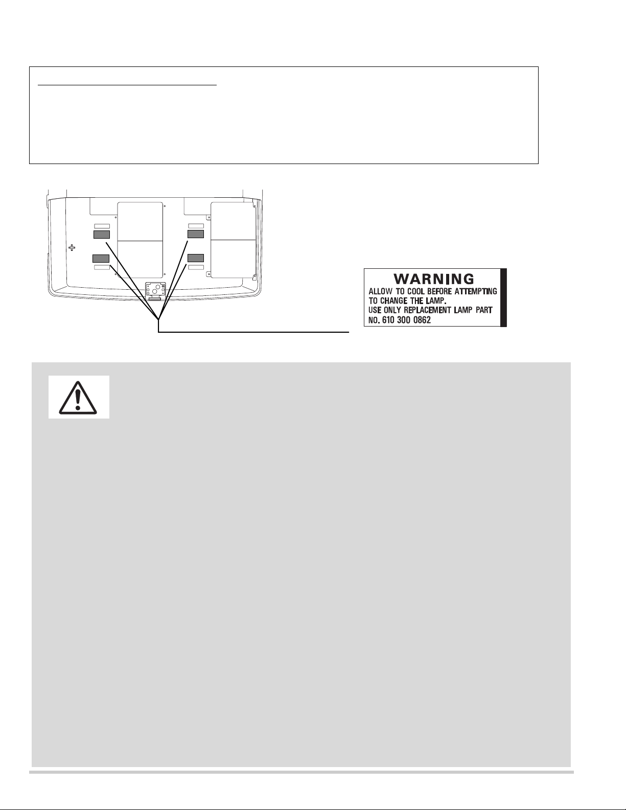
The label of the right figure sticks to here.
-8-
This projector uses a high-pressure lamp which must be handled carefully and properly. Improper
handling may result in accidents, injury, or create a fire hazard.
● Lamp lifetime may differ from lamp to lamp and according to the environment of use. There is no
guarantee of the same lifetime for each lamp. Some lamps may fail or terminate their lifetime in a
shorter period of time than other similar lamps.
● If the projector indicates that the lamp should be replaced, i.e., if the LAMP REPLACE INDICATOR
lights up, replace the lamp with a new one IMMEDIATELY after the projector has cooled down.
( Follow carefully the instructions in the LAMP REPLACEMENT section of this manual. ) Continuous
use of the lamp with the LAMP REPLACE INDICATOR lighted may increase the risk of lamp
explosion.
● A Lamp may explode as a result of vibration, shock or degradation as a result of hours of use as its
lifetime draws to an end. Risk of explosion may differ according to the environment or conditions in
which the projector and lamp are being used.
IF A LAMP EXPLODES, THE FOLLOWING SAFETY PRECAUTIONS SHOULD BE TAKEN.
If a lamp explodes, disconnect the projector’s AC plug from the AC outlet immediately. Contact an
authorized service station for a checkup of the unit and replacement of the lamp. Additionally, check
carefully to ensure that there are no broken shards or pieces of glass around the projector or coming out
from the cooling air circulation holes. Any broken shards found should be cleaned up carefully. No one
should check the inside of the projector except those who are authorized trained technicians and who are
familiar with projector service. Inappropriate attempts to service the unit by anyone, especially those who
are not appropriately trained to do so, may result in an accident or injury caused by pieces of broken
glass.
LAMP HANDLING PRECAUTIONS
ORDER REPLACEMENT LAMP
Replacement Lamp can be ordered through your dealer. When ordering a Projection Lamp, give the
following information to the dealer.
●
Replacement Lamp Type No. : POA-LMP49
(Service Parts No. 610 300 0862)
Lamp replacement caution label
LAMP1
LAMP3
LAMP2
LAMP4
1AA6P4S2207-B
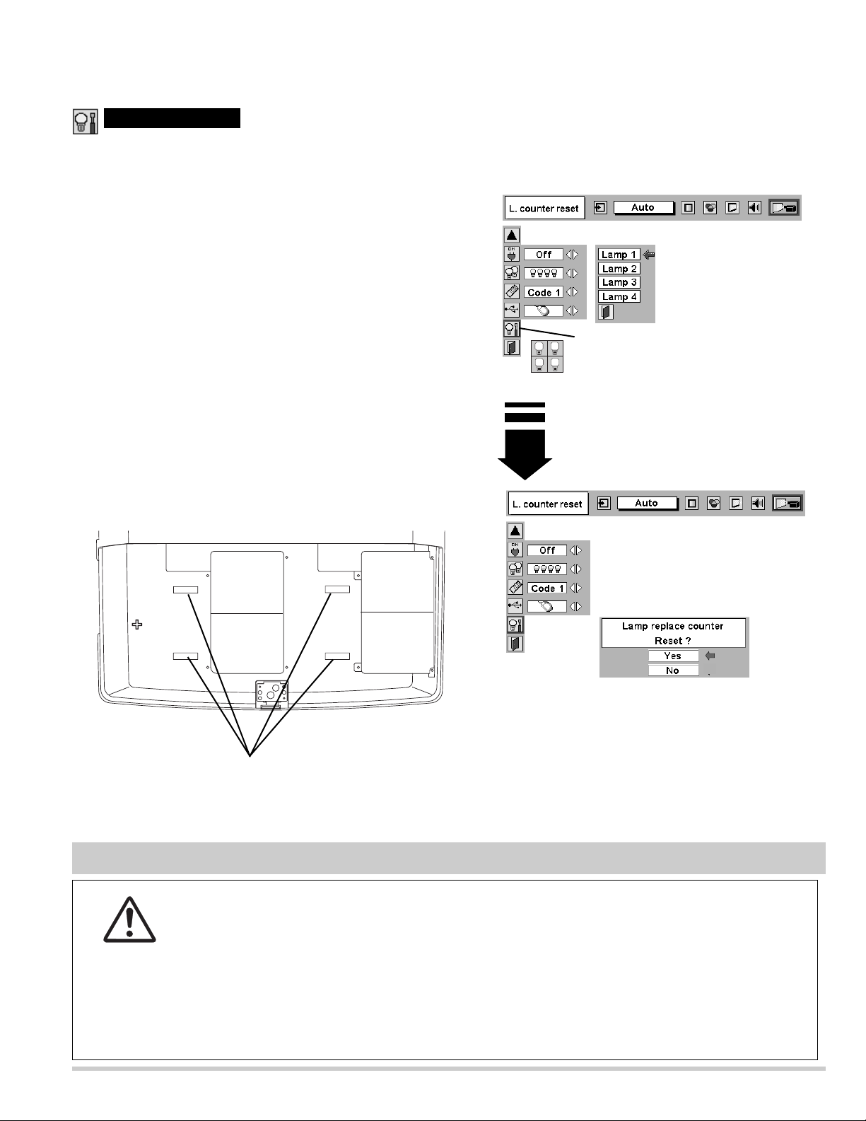
Lamp counter reset
Move pointer to Lamp counter reset and then
press SELECT button. Move arrow to
replaced lamp number (Lamp 1, Lamp
2, Lamp 3 or Lamp 4) and then press
SELECT button.
Be sure to reset Lamp Counter when Lamp Assembly is replaced. When Lamp Replace Counter is reset, LAMP
REPLACE indicator stops lighting.
Turn projector on, press MENU button and ON-SCREEN
MENU will appear. Press POINT LEFT/RIGHT button(s) to
move a red frame pointer to SETTING Menu icon.
1
Press POINT DOWN button to move a red frame pointer to
“Lamp counter reset” and then press
SELECT button.
2
Do not reset Lamp Replace Counter except after Projection lamp is
replaced.
Another confirmation dialog box appears and select [Yes] to
reset Lamp Replace Counter.
4
Move arrow to replaced lamp number (Lamp 1, Lamp 2, Lamp 3
or Lamp 4) and then press
SELECT button. Message "Lamp
replace counter Reset?" is displayed. Move pointer to [Yes] and
then press SELECT button.
3
NOTE: Be sure to reset correct lamp number otherwise LAMP
REPLACE indicator continues lighting.
Message "Lamp replace counter Reset?" is
displayed. Move pointer to [Yes] and then
press SELECT button.
-9-
LAMP1 LAMP3
LAMP4LAMP2
Lamp No. is marked a cabinet
CARRYING AND TRANSPORTING A PROJECTOR
●Do not drop or bump a projector, otherwise damages or malfunctions may result.
●When carrying a projector, use a suitable carrying case.
●Do not transport a projector by using a courier or transport service in an unsuitable transport
case. This may cause damage to a projector. To transport a projector through a courier or
transport service, consult your dealer and best case should be applied.
CAUTION IN CARRYING OR TRANSPORTING A PROJECTOR
LAMP1
LAMP3
3
1
2 4
LAMP2
LAMP4

Mechanical disassemblies
Remove 8 screws and remove the Cabinet -
top.
Note :
Be careful not to damage Hook.
The cabinet-front-top is being
fixed with cabinet-front-bottom by
hook.
1. Remove 2 screws-A. Push part(a) and pull
the Cabinet-front-top up.
2. Remove 4 screws-B and remove the Cabinet
front bottom.
3. Remove 11 screws-C and remove the
Cabinet front.
Refer to Lens replacement and installation
manual.
1.
Cabinet-front-top,
Cabinet-front-bottom
and Cabinet-front removal.
2.
Cabinet-top removal.
-10-
Disassemble should be made following procedures in numerical order.
Following steps show the basic procedures, therefore unnecessary step may be ignored.
Caution:
The parts and screws should be placed exactly the same position as the original otherwise it may cause lose of
performance and product safety.
C
Hook
A
C
C
Cabinet front top
C
(a)
C
C
C
B
B
B
B
A
(a)
Cabinet front
C
C
C
Cabinet front bottom
C
C
abinet top
-11-
MAIN
1. Remove the control-switch-unit upward.
2. Remove the Terminal-slots-unit upward.
Remove the connectors and the flexible
cables of the LCD panels from the assembly
Main. (Never touch the electrode of flexible
cables.)
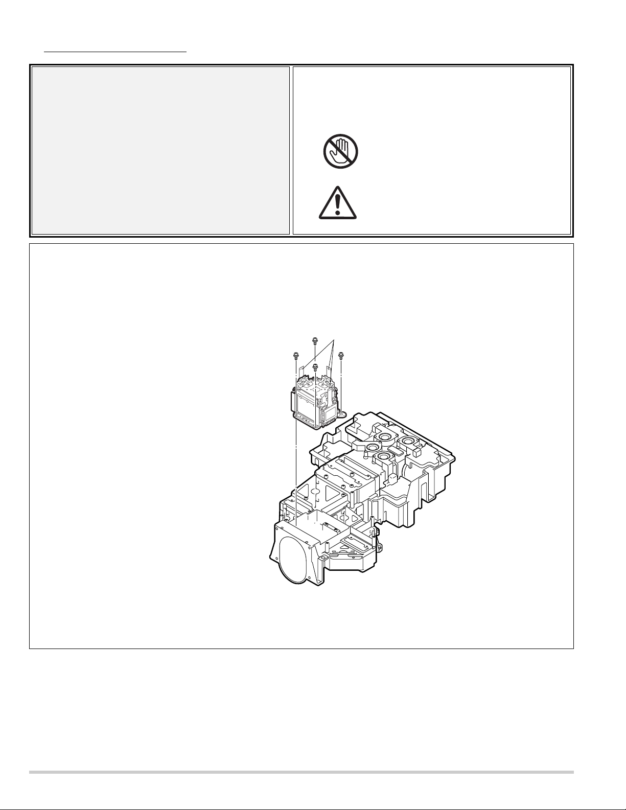
Remove 6 screws and remove the assembly
main.
3.
Assembly Main removal.
4.
Control-switch-unit and
Terminal-slots-unit removal.
Mechanical disassemblies
Term
U
inal slots
nit
Control-SW
Unit
-12-
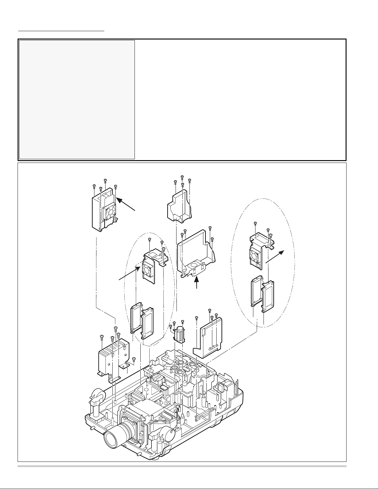
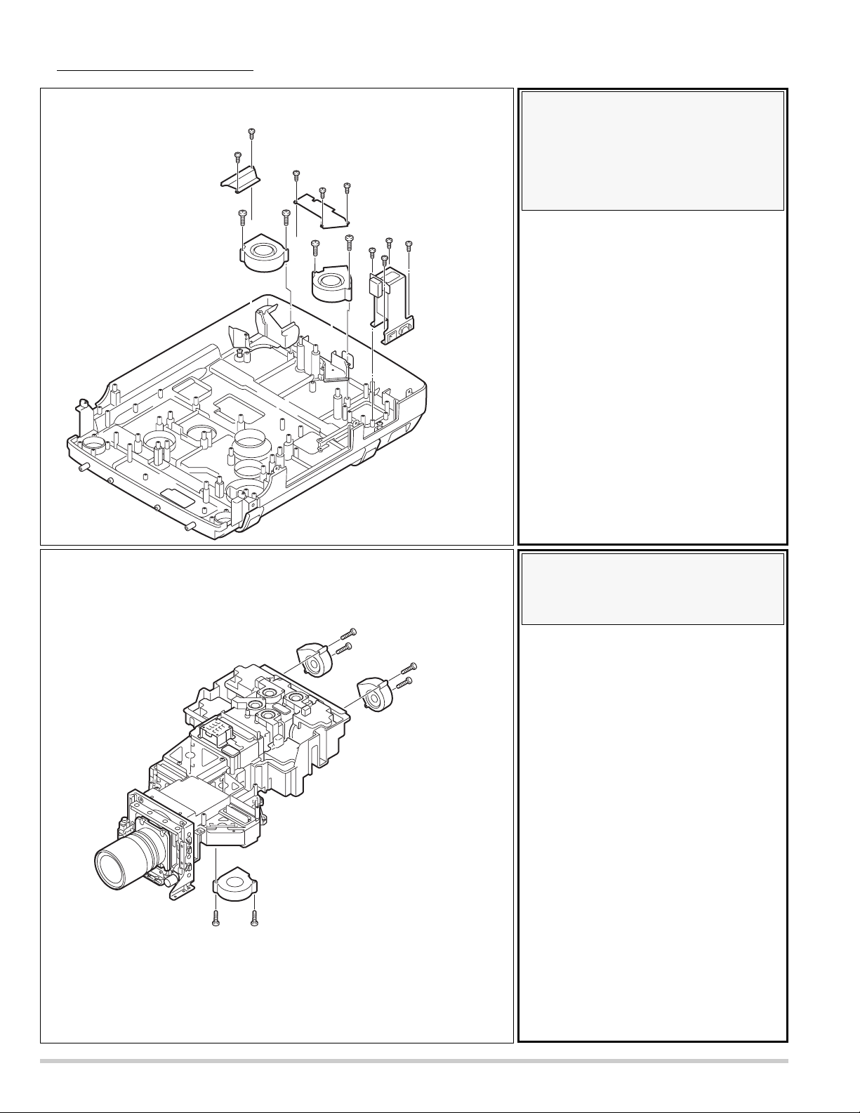
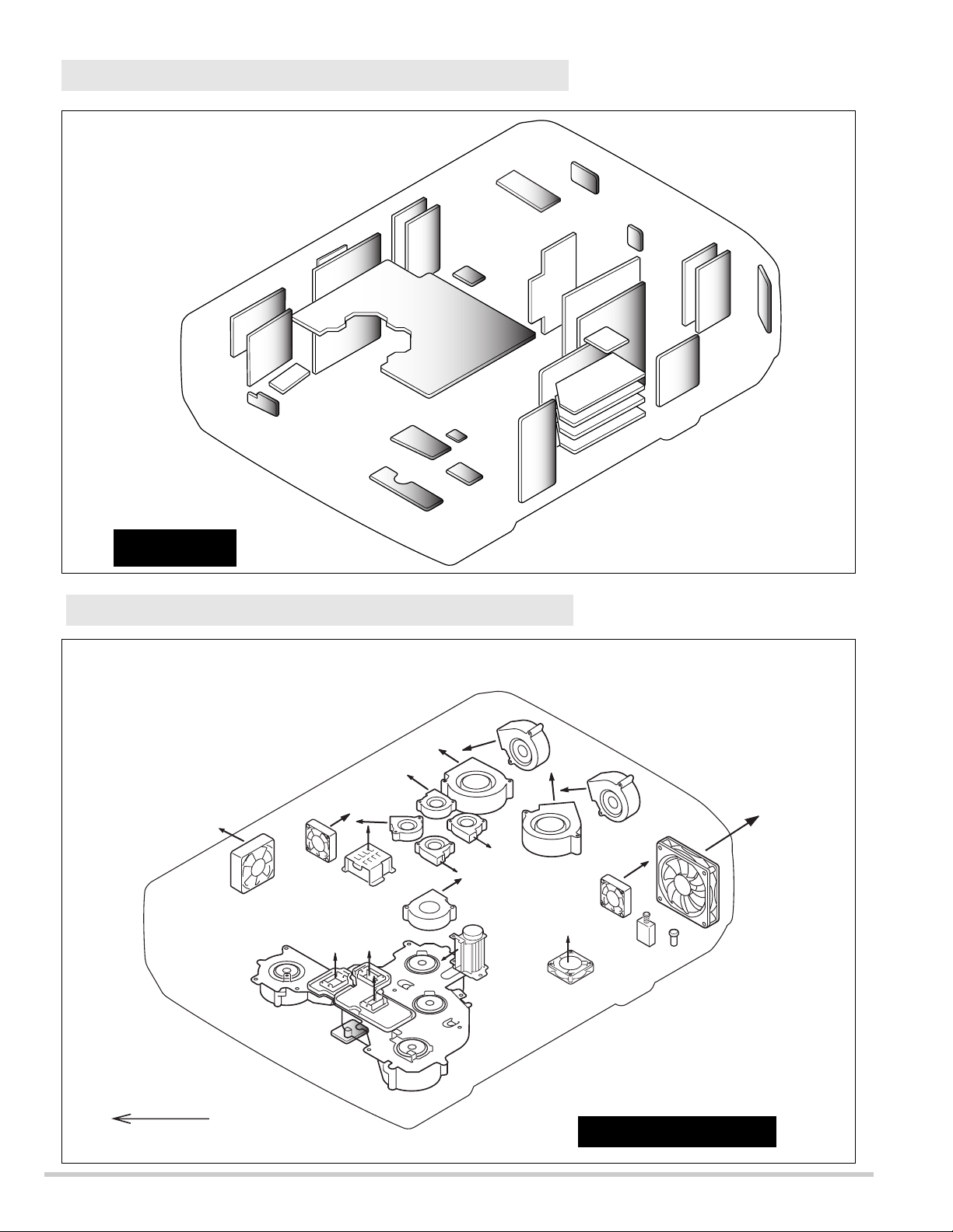
1. Remove 4 screws-A ,1 screw-B and remove the assembly motor & audio.
(Motor & audio unit and SW-power supply unit remove at the same time.)
2. Remove 4 screws-C and remove the assembly PFC3-4.
3. Remove 2 screws-D , 2 screws-E and remove the assembly power.
4. Remove 4 screws-F and remove the assembly PFC1-2.
5. Remove 2 screws-G , 1 screw-H and remove the assembly Lamp-ballast1-2.
6. Remove 2 screws-I , 1 screw-J and remove the assembly Lamp-ballast3-4
7. Remove 3 screws-K and remove the Fan(FN901).
8. Remove 4 screws-L and remove the assembly sub-power.
Note :
Mark the Fans as they are removed from the cabinet bottom so that
they may be reassembled in the same location from which they were
removed.
Be careful of the attachment direction of Fans.
See arrow mark in a figure.
5.
Assemblies PFC, assembly
power, assembly sub-power,
assemblies lamp-ballast , assembly Motor & Audio and
Fan(FN901) removal.
Mechanical disassemblies
C
C
L
C
C
The direction
of a wind.
(FN914)
L
L
L
Sub power
Moter & audio
(SW-Power supply)
PFC3-4
The direction
of a wind.
(FN907)
Lamp ballast 3-4
assembly
A
A
A
A
Ballast4
B
F
I
I
Ballast3
F
J
PFC1-2
K
K
K
F
The direction
of a wind.
(FN913)
E
D
Fan(FN901)
F
E
D
Power
G
Ballast2
Lamp ballast 1-2
assembly
G
H
The direction
of a wind.
(FN908)
Ballast1
-13-
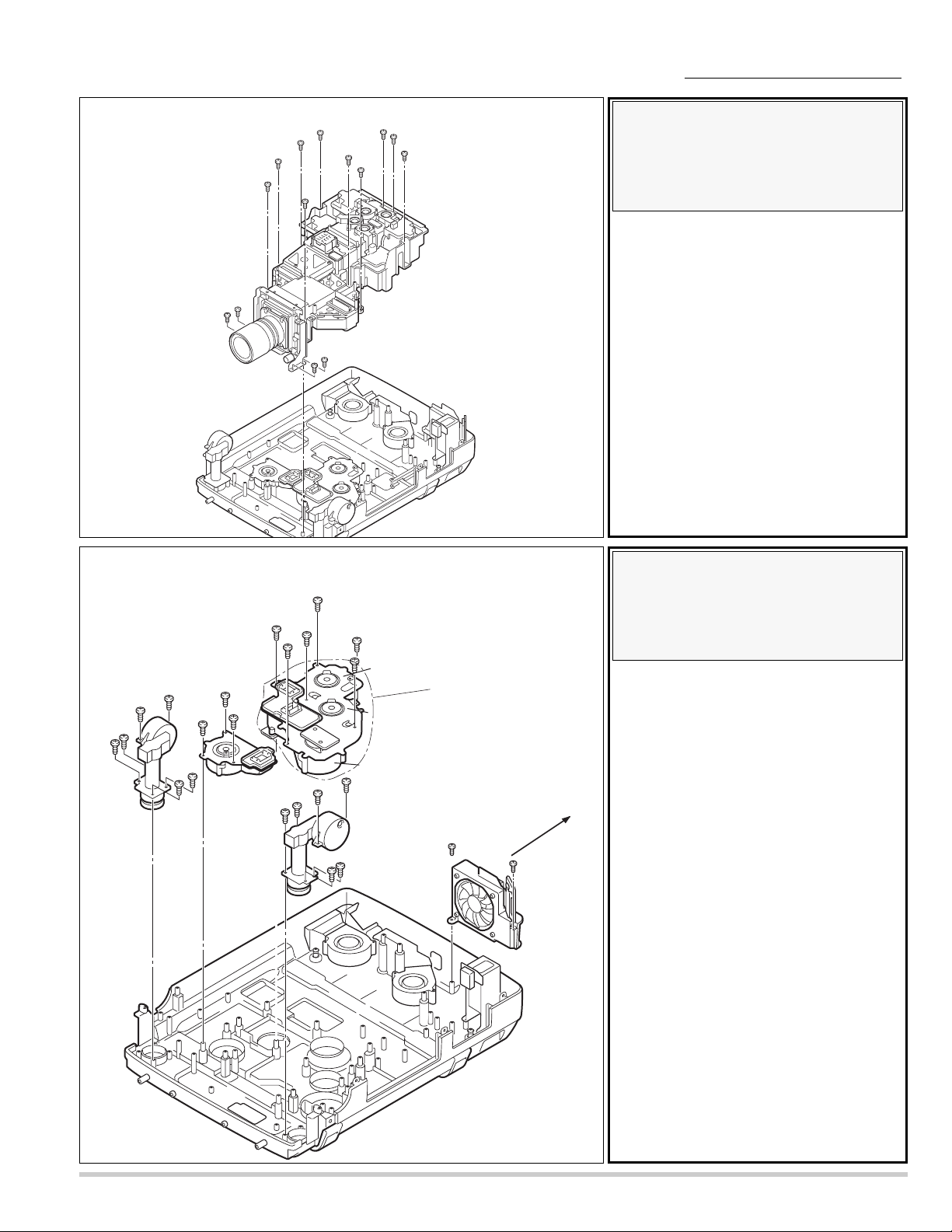
Note:
When remove the Optical unit upward, do not
having projection lens.
Remove 10 screws-A, 4 screws-B and remove
the Optical unit upward.
6.
Optical unit removal.
Mechanical disassemblies
Note :
Mark the Fans as they are
removed from the cabinet bottom
so that they may be reassembled
in the same location from which
they were removed.
Be careful of the attachment
direction of Fan(FN906).
See arrow mark in a figure.
1. Remove 6 screws-A and remove the
adjustable-foot-left.
2. Remove 6 screws-B and remove the
adjustable-foot-right.
3. Remove 3 screws-C and remove the Fan
( FN903 ).
4. Remove 6 screws-D and remove the Fan
unit ( FN904 ,905, 916).
5. Remove 2 screws-E and remove the Fan
( FN906 ).
7.
Fans( FN903, FN904, FN905,
FN906, Fn916 ), and
Adjustable-feet removal.
A
A
A
A
A
A
A
A
A
A
B
B
B
B
Optical Unit
A
Adjustable
foot-left
D
D
D
D
A
A
A
C
C
C
D
D
FN904
FAN unit
FN916
A
A
FN903
Adjustable
foot-right
B
B
B
FN905
B
E
B
B
FN906
The direction
E
of a wind
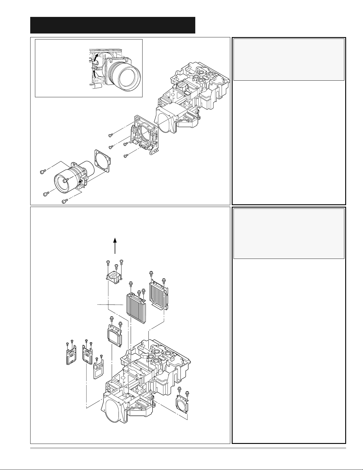
1. Remove 2 screws-A, 2 screwsB and remove the Fan (FN909).
2. Remove 3 screws-C, 2 screwsD and remove the Fan (FN910).
3. Remove 4 screws-E and Main
switch unit.
-14-
Note :
Mark the Fans as they are
removed from the optical unit so
that they may be reassembled in
the same location from which
they were removed.
1. Remove 2 screws-A and remove the Fan
(FN911).
2. Remove 2 screws-B and remove the Fan
(FN912).
3. Remove 2 screws-C and remove the Fan
(FN915).
9.
Fans ( FN911, FN912 and
FN915 ) removal.
8.
Fans ( FN909, FN910 ) and
Switch assembly removal.
Mechanical disassemblies
t
A
A
C
C
C
B
FN909
B
E
D
FN910
D
E
E
E
MAIN-SW uni
FN911
B
B
A
A
FN912
FN915
C
C
-15-
Optical unit disassemblies
Note :
(1) Each polarizer unit uses different
characteristic polarization glasses.
Mark the polarizer units as they are
removed from the optical unit so
that they may be reassembled in
the same location from which they
were removed.
(2) Be careful of the attachment
direction of Fan (FN902).
See arrow mark in a figure.
1. Remove 2 screws A and remove the
Integrator lens in unit.
2. Remove 3 screws B and remove the
Integrator lens out / PBS unit.
3. Remove 2 screws C and remove the
Condenser lens unit.
4. Remove 2 screws D and remove the Relay
lens unit.
5. Remove 6 screws E and remove the 3
Polarizer units.
6. Remove 3 screws F and remove the
Fan(FN902) upward.
1. Slide the lens lock lever on the projector to
"UNLOCK" (UPPER) position and install
the Projection lens with Mount Parts to the
Holder lens unit.
(Refer to Lens replacement and Installation
procedures manual)
When making unlocking, add the hand so
as not the fall.
2. Loosen 4 screws-A and remove the
Projection lens.
For the loss prevention, the screw does not
come.
3. Remove 4 screws-B and remove the
Holder-lens unit.
1.
Projection lens and Holder-
lens unit removal.
2.
Integrator-lens-in unit,
Integrator-lens-out/PBS unit,
Condenser-lens unit, Relay-lens
unit, Polarizer units and
Fan(FN902) removal.
Lens lock lever
Unlock(upper)
position
Projevtion lens
A
A
A
A
Integrator-lens-out/
PBS unit
Lens mount
Fan(FN902)
Condenser-lens
unit
E
E
Holder lens unit
B
B
B
B
The direction
of a wind.
F
F
F
A
B
B
B
C
C
E
E
A
Integrator-lens-in
unit
Polarizer
unit
Red
Green
Blue
E
E
D
D
Relay-lens
unit
-16-
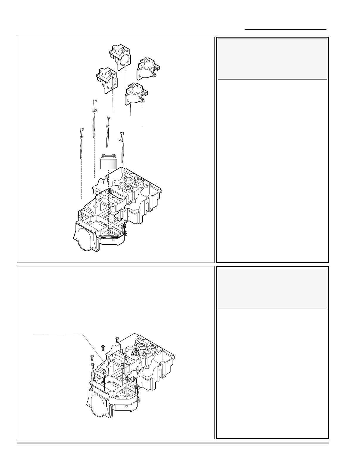
1. Remove 11 screws and remove the Optical
base top.
Note :
The characteristics and ages of
lamps are managed by CPU.
Mark the lamp assemblies as they
are removed from the optical unit
so that they may be reassembled
in the same location from which
they were removed.
Do not touch with bare hand in
the mirror.
Each mirror uses different characteristic optical filter glasses. Mark
the mirrors as they are removed
from the optical unit so that they
may be reassembled in the location and direction from which
they were removed.
1. Loosen 8 screws Aand remove the 4 Lamp
assemblies. (Two screws at each Lamp.)
2. Remove 5 stoppers and pull the 5 mirrors
upward.
3.
Assemblies lamps and mirrors removal.
4.
Optical base top
removal.
Optical unit disassemblies
Lamp-3
Stopper-A
Dichroic Mirror(C)
Stopper-B
Mirror(R)
Mirror(B-cold)
Lamp-4
A
Stopper-B
A
A
A
A
Stopper-B
Dichroic Mirror(Y)
Stopper-B
Mirror(B-cold)
A
A
A
Lamp-1
Lamp-2
Optical base top
-17-
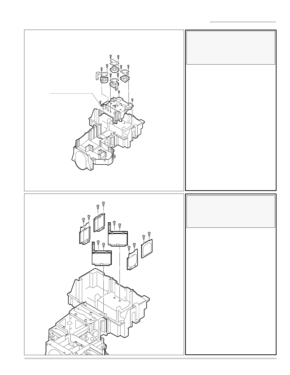
Note :
Mark the Fans as they are
removed from the cover mirror so
that they may be reassembled in
the same location from which
they were removed.
1. Remove 4 screws A and remove the cover
mirror.
2. Remove 8 screws B, plate and remove the
Fan(FN917, FN918, FN919, FN920 ).
(It hooks the plate to the cover mirror inside)
5.
Cover mirror and
Fan(FN917,918,919,920)
removal.
Cover mirror
Optical unit disassemblies
Note :
Each optical filter unit uses different characteristic optical filter
glasses. Mark the optical filter
units as they are removed from
the optical unit so that they may
be reassembled in the same location from which they were
removed
1. Remove 4 screws Aand remove the 2 mirror units.
2. Remove 8 screws B and remove the 4 optical filter units.
6.
Optical filter units and
Mirror units removal.
Fan(FN920)
Fan(FN919)
BB
B
B
B
A
B
B
Fan(FN917)
A
A
B
Fan(FN918)
A
B
Optical-filter units
B
Mirror-units
B
B
A
A
B
A
A
B
B
B
Optical-filter units
-18-
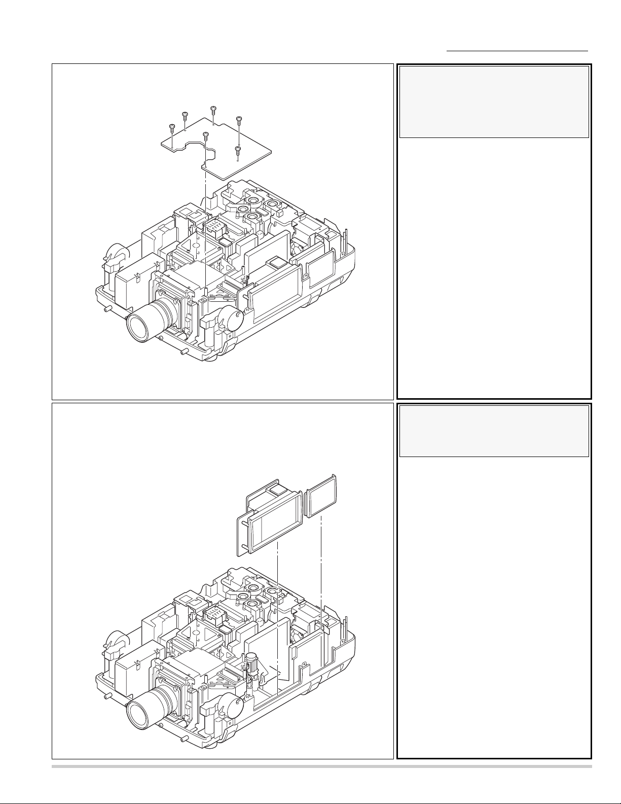
7.
Prism/ LCD panel assembly removal
Note :
Prism / LCD panel assembly is a precision part.
be sure to handle this part with special attention.
Do not drop it or give it excessive force. It may
damage the parts and alignment.
Remove 4 screws and remove the Prism / LCD panel assembly.
At the time, be careful not to damage the Prism / LCD panel
assembly with the driver.
Caution :
(1). Never touch the LCD panel and prism
part directly with hand. Otherwise the
optical parts may get dirty.
(2). Since the LCD panel is equipped with
CMOS-LSI, pay attention to static electricity.
And never touch the electrode of flexi-
ble cables.
Optical unit disassemblies
Never touch
the electrode of flexible cables.
Prism/LCD panel assembly
-19-
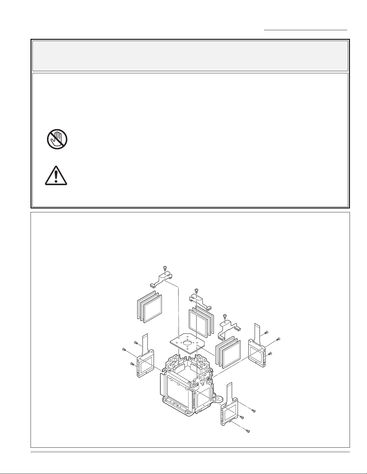
8.
LCD panel, Polarized glass, Optical filter removal.
Optical unit disassemblies
1. Remove 9 screws-A and remove the LCD panel . (3 screws per one LCD panel.)
2. Remove 3 screws-B and remove stoppers.
3. Remove polarized glasses,optical filteres upward.
Note: Each polarizer unit uses different characteristic polarization glasses. Mark the polarizer units as they are removed from the optical
unit so that they may be reassembled in the same location from which they were removed.
Caution :
(1). Never touch the LCD panel directly with hand. Otherwise the optical parts may get dirty.
(2). Since the LCD panel is equipped with CMOS-LSI, pay attention to static electricity.
And never touch the electrode of flexible cables.
Note :
Don't remove all three LCD panels at the same time. The standard in convergence
adjustment runs out and it becomes not possible to do an adjustment.
When exchanging three LCD panels at the same time, it recommends to exchange every
in the Prism/LCD panel assembly.
tical filter
p
O
A
Polarized glass(Hout)
A
Polarized glass(out)
A
LCD panel (Red)
Stopper
B
B
Stopper
B
Stopper
A
A
A
LCD panel (Green)
A
A
A
LCD panel (Blue)
-20-
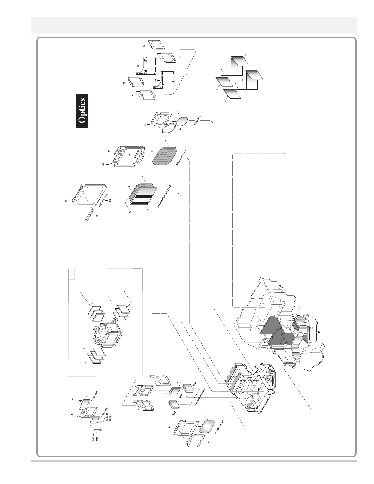
101
PRISM ASSEMBL Y (PBS)
102
DICHROIC MIRROR (Y/IA)
103 DICHROIC MIRROR (C)
104 POLARIZED GLASS (IN/B)
105 POLARIZED GLASS (IN/G)
106 POLARIZED GLASS (IN/R)
107 POLARIZED GLASS (HIN/B)
108
POLARIZED GLASS (HIN/G)
109 POLARIZED GLASS (HIN/R)
110 OPTICALFILTER
111 OPTICAL FILTER
112 OPTICALFILTER (UV/IR)
113 OPTICALFILTER (UV cut )
114 MIRROR (B-COLD)
115 MIRROR (R)
116 MIRROR (COLD)
118 LENS-CONDENSER(OUT)
119 LENS-CONDENSER (IN)
120 LENS-RELAY (OUT)
121 LENS-RELAY (IN)
122 LENS-CONDENSER(G)
123
LENS-INTEGRATOR
124 PRISM ASSEMBLY
KEY No.
DESCRIPTION
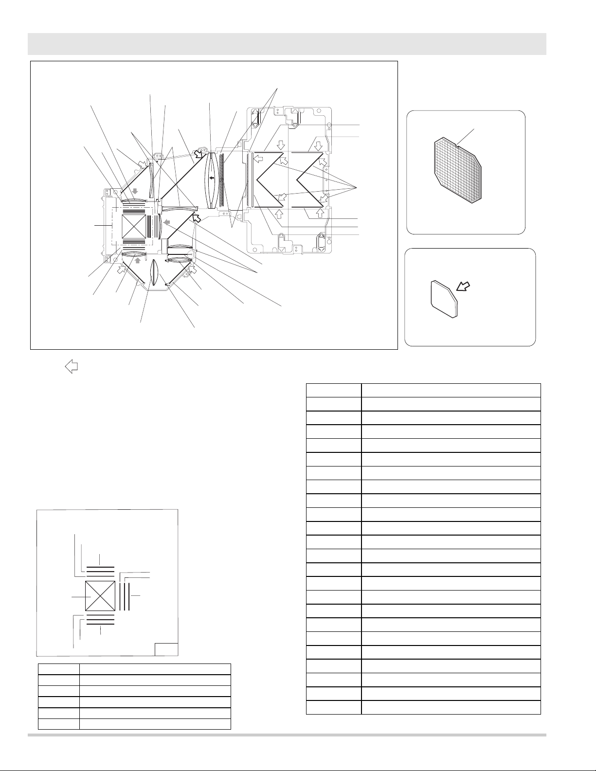
Optical parts Location and direction
124-1
124-2
124-3
124-4
124-5
124-6
PRISM ASSEMBLY
OPTICAL FILTER (WV)
POLARIZED GLASS(HOUT/QU)
POLARIZED GLASS (OUT/R)
POLARIZED GLASS (OUT/G)
POLARIZED GLASS (OUT/B)
D
Integrator lens
The optical parts name (description)
can see it on parts-list.(page-78)
There is a directionality (the gradation) if installs the
Dichroic Mirror for the putting a marker comes always
to the position of the figure.
Lamp side
F
Optical filter (UV cut)
Without LCD Panel
in the figure.
No.123
No.113
106
A : The printed marker comes this side.
B : Plane surface comes this side.
C : Spherical surface comes this side.
D : Slot part comes this top side.
E : Glass shoud be placed as the film attached
side comes to the LCD panel side.
F : Big chamfer comes this top side.
G : The printed marker comes top side.
PRISM ASSEMBLY
124-1
105
124
122
109
118
115
108
103
B
Red
Green
Blue
104
121
107
114
120
124-4
124-3
124-3
124-6
124-2
124-2
G
(BLUE)
(RED)
G
124-5
124-3
G
124-2
(GREEN)
124
119
101
D
122
121
114
113
C
(Optical filter)
102
123
F
110
111
116
111
110
112
-21-
124-6
124-3
124-2
Blue
12
4
-2
1
2
4
-3
1
2
4
-4
Red
124-2
124-3
124-5
Green
Film side
Film side
A
F : Big chanfer comes this top side.
p
102
103
123
123
119
118
118
122 122
121
121
120
116
116
116
116
115
114
114
113
112
111
111
110
110
122
109
108
107
106
105
104
107 (B)
108 (G)
109 (R)
104 (B)
105 (G)
106 (R)
G:
Printed marker comes this top side.
(R,G)
52 (B)
Prism assembly (Without LCD Panel)
124
Film
side
F
ilm
s
id
e
F
101
G
G
G
(R,G)
68 (B)
Optical parts location --- The optical parts name(description) can see it on parts-list.
-22-
PWB assembles location
Motor fans location
Motor fans location
allast 4
B
AC net
3-4
PFC
ain
M
Front LED
otor & A
M
SW-Powr supply
udio
F-G
net
R
/C
1
allast 3
B
S
ensor
Lamp fannet
Fan
n
et1
Sub pow
other
M
G
C
Fan net 2
er
PFC
Pow
Terminal board
1-2
er
Lam
p net 1
R
/C
2
allast 2
B
allast 1
B
ear LED
R
trol
on
C
PWB assemblies
location
Front side
Front side
For Lamp ballast
FN914
For PFC3-4
FN903
For R-panel
FN908
FN919
FN904
N
et
For Lamp-3
FN909
FN920
FN902
For PBS
FN917
Fan net 3
For PBS
For Lamp-4
FN915
For B,G -panel
232C
S
R
FN912
FN918
FN910
For Lamp-1
FN901
For B-opt. filter
FN916
For Lamp-2
FN911
For Lamp ballat
Interlock SW
FN913
For PFC1-2
907
FN
SW902
For Exhaust
FN906
F901
Direction of a wind.
FN905
-23-
AIR FILTER
AIR INTAKE VENTS
This projector is equipped with cooling fans for protection from overheating. Pay attention to following to
ensure proper ventilation and avoid a possible risk of
fire and malfunction.
-Do not cover vent slots.
-Keep bottom clear any objects.
Obstructions may block cooling air.
When Air filter cleaning, it clean the vent slots,too,at
the same time.
AIR INTAKE VENTS
MAINTENANCE
WARNING TEMP. INDICATOR
Ventilation Slots of a projector may be blocked. In such an event, reposition a projector so that Ventilation Slots are not
obstructed.
Air Filter may be clogged with dust particles. Clean Air Filter by following section AIR FILTER CARE AND CLEANING
on next page.
1
2
If WARNING TEMP. Indicator remains on after performing above checks, Cooling Fans or Internal Circuits may be
malfunctioning. Contact service personnel from an authorized dealer or a service station.
3
WARNING TEMP. Indicator flashes red and projector is automatically turned off when an internal temperature of a projector
exceeds normal temperature. Wait at least 5 minutes before turning on projector again.
When WARNING TEMP. Indicator continues to flash, check items listed below.
EXHAUST VENT
HOT AIR EXHAUSTED !
Air blown from exhaust vent is hot. When using
or installing a projector, following precautions
should be taken.
● Do not put a flammable object near this vent.
● Keep rear grills at least 3’ (1m) away from any
object, especially heat-sensitive object.
An exhaust is reflected and the cooling becomes
bad when there is any thing near the exhaust vents.
The heat causes temperature rise inside the
staying.
● Do not touch this area, especially screws and
metallic parts. This area will become hot while a
projector is used.
HOT
-24-
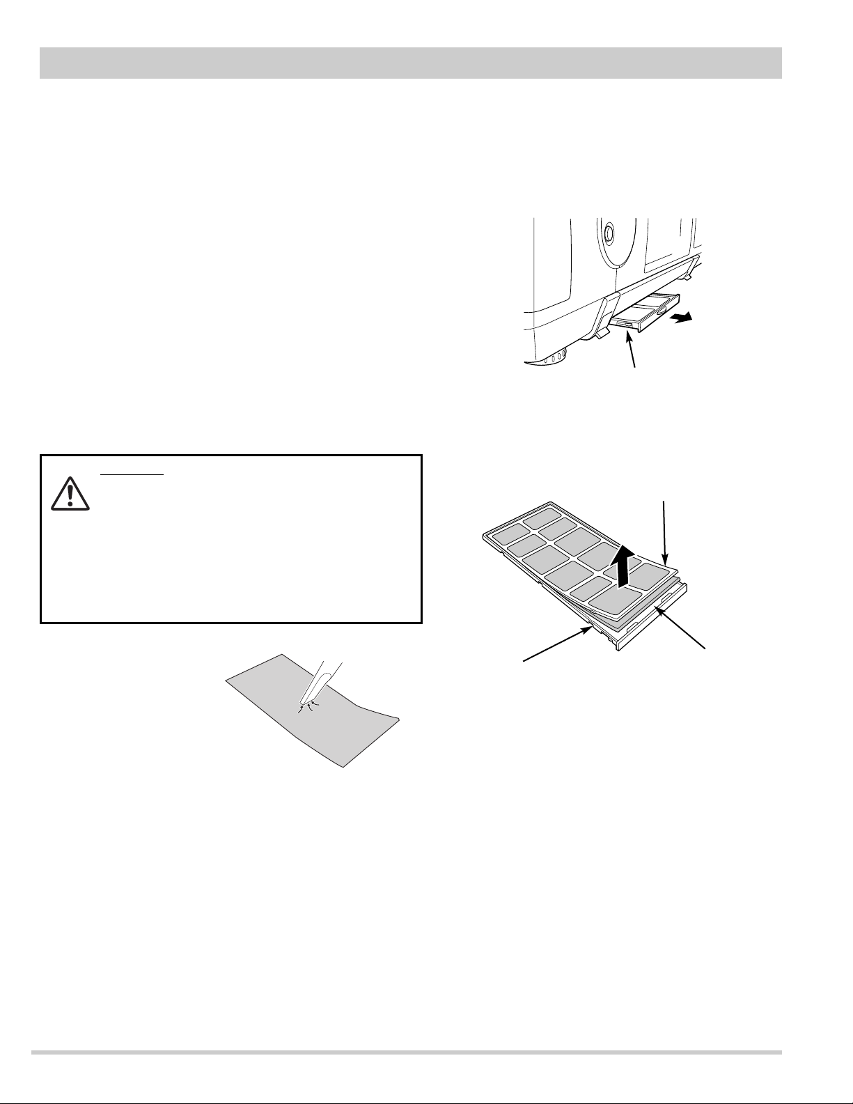
AIR FILTER CARE AND CLEANING
Air Filter prevents dust from accumulating on surface of Projection Lens and Projection Mirror. Should Air Filter
become clogged with dust particles, it will reduce Cooling Fans' effectiveness and may result in internal heat build up
and adversely affect life of a projector.
Clean Air Filter following steps below:
1
Turn power off, and disconnect AC power cord from AC
outlet.
2
Pull out air filter unit from a projector.
3
Pulling up center frame of air filter top, separate air filter
top and sheet from air filter base.
4
Clean each parts with brush or wash out dust and
particles.
Be sure to dry them out.
5
Assemble sheet and air filter and replace air filter to a
projector.
CAUTION
Do not operate a projector with air filter removed.
Dust may accumulate on LCD panel and Mirror
degrading picture quality.
Do not put small parts into air Intake Vents. It may
result in malfunction of a projector.
The filter be careful and handle. the effect of the
filter runs out in case of a leak and it being broken
off.
AIR FILTER UNIT
AIR FILTER TOP
AIR FILTER BASE
SHEET
Cleaning of the sheet
When Air filter cleaning, it clean the air intake
vents, at the same time.
-25-
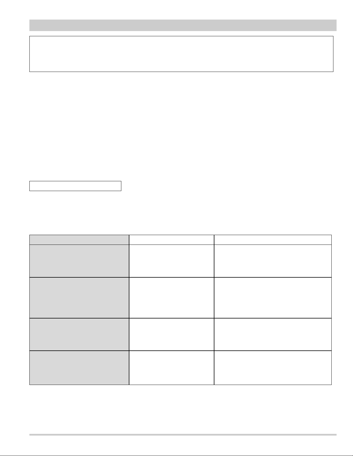
Improvement of the Optical parts
1. When the garbage adheres to the surface basically about all optical parts,it is desirable to
clean in air spray and so on.
2. When the above way can not be removed,wipe the dry cleaning with wiping cloth
and the wiper there is little time dust and so on.
3. When the above way can not be removed,soak a few medicines in the cloth as follows and wipe
up them lightly. After that,always wipe the dry cleaning cloth.
Optical parts Medicines Remark
LCD panel
Iso-propyl-alcohol
In case of cleaning,pay attention
to the static electricity and specifically,don't touch the terminal of FPC.
Polarized glass
(Glass with plastics sheet)
Methanol
Synthetic detergent
Iso-paraffin liquid
Wipe up lightly.
Because there is fear that the film
comes off the substrate when wiping
up by the strong power.
Dichroic mirror
Optical filter
(Glass with the surface coat)
Alcohol
(methanol:ethel=8:2)
Lens kind
Condenser lens
Integrator lens
Prism
Ethanol
The list of the medicine to recommend
Disassembly Cleaning
Disassembly cleaning method should only be performed when the unit is considerable
dirty and cannot be sufficiently cleaned by air spraying alone.
Be sure to readjust the optical system after performing disassembly cleaning.
Caution :
The surface of the optical components consists of multiple dielectric layers with varying degrees of refraction.
Never use organic solvents (thinner, etc.) or any kind of cleanser on these components.
Since the LCD panel is equipped with an electronic circuit, never use any liquids (water,etc.) to clean the unit.
Use of liquid may cause the unit to malfunction.
After long of use,dust and other particles will accumulate on the LCD panel,prism,mirror,polarized
glass,lens,etc.,causing the picture to darken or color to blur. If this occurs,clean the inside of optical unit.
Remove dust other particles using air spray. If dirt cannot be removed by air spray, disassemble and clean the optical
unit.
Caution:
Use a commercial (inert gas) air spray designed for cleaning camera and computer equipment.
Use a resinbased nozzle only. Be very careful not to damage optical parts with the nozzle tip.
Never use any kind of cleanser on the unit. Also, never use abrasive materials on the unit as this
may cause irreparable damage.
-26-
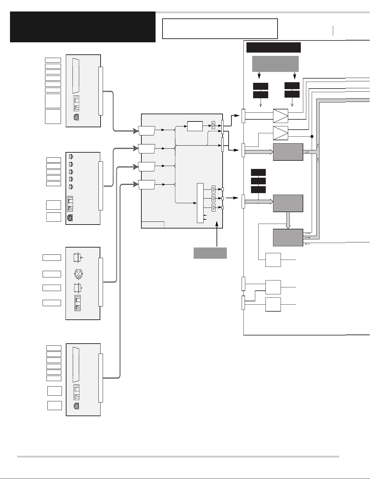
CHECK
RGB SIGNAL
IC 501
IC 1501
DIGITAL SIGNAL
ANALOG SIGNAL
IC340 1
VIDEO
ENHAN CER
IC401
DIGITA L
GAMMA
BUFFE R
IC426 1/427 1
/4281
IC420 1
PROGR ESSIV E
SCAN
CONVE RTER
IC230 1
SW
FPGA
A/D
IC220 1
BUFFE R
IC201 /211
/221
BUFFE R
IC820 1 IC 8211
IC822 1
IC301
SCAN
CONVE RTER
IC240 1
CLOCK
CONVE RTER
DIGITA L
S&H
DIGITA L
S&H
DIGITA L
S&H
DIGITA L
S&H
DIGITA L
S&H
DIGITA L
S&H
IC440 1
GHOST
CANCE LER
CHECK
SYNC SIGNAL
Troubleshooting
NO PICTURE -1
TERMINAL BOARD DVI
DATA
R
G
B
H
V
AUDIO
INPUT
CONTROL
PORT
R
G
B
TERMINAL BOARD-COMPONENT
R/Pr
G/Y
B/Pb
H/HV
V
AUDIO
INPUT
CONTROL
PORT
R
G
B
INPUT-1
INPUT-2
INPUT-3
INPUT-4
CG MOTHER
SW- SYNC
HV
SW- R G B
SLOT SEL1
SLOT SEL2
Assembly Main
ANALOG
H
V
TP-32H1
TP-32V1
TP-HV
H
V
TP-V
H
V
IC8261
IC8251
DVI
BUFFER
BUFFER
IC8201 IC8211
IC8201 IC8211
IC8221
IC8221
DIGITAL SIGNAL
DIGITAL SIGNAL
TP-201
R
G
B
TP-211
TP-221
BUFFER
BUFFER
IC201/211
IC201/211
/221
/221
ANALOG SIGNAL
ANALOG SIGNAL
DIGITAL
H
V
V
H
H
TERMINAL BOARD AV
TERMINAL BOARD-D-SUB15
VIDEO-Y
S-VIDEO
VIDEO-C
AUDIO INPUT
R
G
B
H
V
I I C
AUDIO
INPUT
ANALOG RGB INPUT
CONTROL
PORT
R
G
B
R
G
B
The Terminal board D-SUB15 does
not exist in some particular models.
A/D
A/D
IC2201
IC2201
CLP
IC281
RS232C
SWITCH
USB
IC9801
FROM
IC2301
FROM
CPU
FROM
CPU
H
IC 501
IC 1501
IC340 1
VIDEO
ENHAN CER
IC401
DIGITA L
GAMMA
BUFFE R
IC426 1/427 1
/4281
IC420 1
PROGR ESSIV E
SCAN
CONVE RTER
IC230 1
SW
FPGA
IC301
SCAN
CONVE RTER
IC240 1
CLOCK
CONVE RTER
DIGITA L
S&H
DIGITA L
S&H
DIGITA L
S&H
DIGITA L
S&H
DIGITA L
S&H
DIGITA L
S&H
GREEN
LCD
PANEL
RED
LCD
PANEL
BLUE
LCD
PANEL
IC440 1
GHOST
CANCE LER
-27-
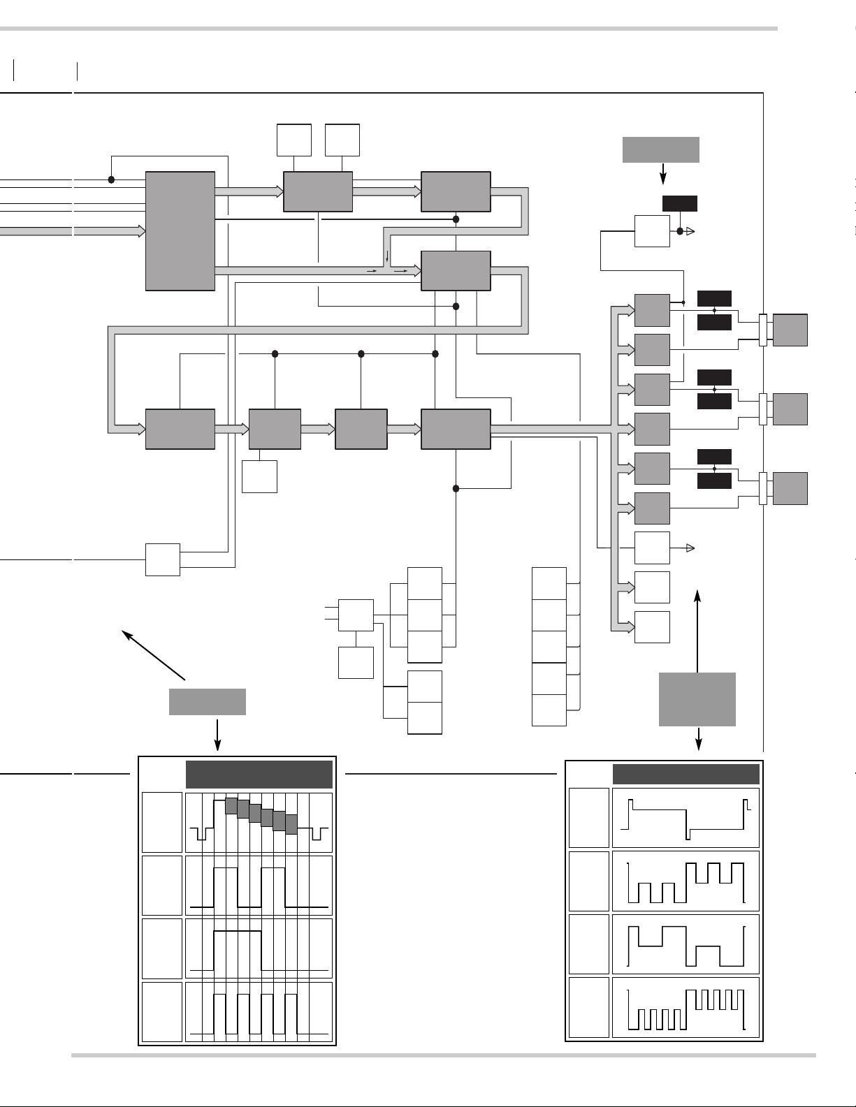
CHECK
RGB SIGNAL
CHECK
PSIG SIGNAL
CHECK
LCD PANEL
DRIVE
SIGNAL
VCO1
IC4231
H
IC4201
IC4201
PROGRESSIVE
V
V
H
IC2301
IC2301
SW
SW
FPGA
FPGA
H/V
PROGRESSIVE
SCAN
SCAN
CONVERTER
CONVERTER
H/V
IC3401
IC3401
VIDEO
VIDEO
ENHANCER
ENHANCER
IC2401
IC2401
CLOCK
CLOCK
CONVERTER
CONVERTER
VCO2
IC2403
NOTE:
IC4401 is used only for "UXGA" model.
H
SW
IC8253
GREF
RS232C
USB
Timing Chart
INPUT
SIGNAL
TP201
RED
IC6301
MEMORY
IC6321
SGRAM
IC6341
IC6361
H/V
SYSTEM BUS
H/V
IC4401
IC4401
GHOST
GHOST
CANCELER
CANCELER
CPU
IC801
I/O EXP.
GREF
BUFFER
BUFFER
BUFFER
IC4261/4271
IC4261/4271
/4281
/4281
IC301
IC301
SCAN
SCAN
CONVERTER
CONVERTER
H/V
IC401
IC401
DIGITAL
DIGITAL
GAMMA
GAMMA
FILP
FLOP
MEMORY
FLASH
MEMORY
SRAM
H/V
SYSTEM BUS
SYSTEM BUS
IC871
IC892
IC1311
IC1351
IC1352
IC1341
IC1331
MEMORY
EEP-ROM
MEMORY
FLASH
MEMORY
SRAM
OSC
OSC
TP2561
PSIG
IC2561
IC2571
IC2581
TP-2561
IC2591
PSIG
IC1501, IC1531 and IC1561
are used only for "UXGA" model.
DIGITAL
DIGITAL
S&H
S&H
DIGITAL
DIGITAL
S&H
S&H
DIGITAL
DIGITAL
S&H
S&H
DIGITAL
DIGITAL
S&H
S&H
DIGITAL
DIGITAL
S&H
S&H
DIGITAL
DIGITAL
S&H
S&H
BUFFER
IC406/407
/408
TTL
TTL-ECL
IC3351
DAC
IC3561
PSIG1~4
TO LCD
PANE L RGB
TP-2517
TP-2516
IC501
IC1501
TP-2527
IC531
TP-2526
IC1531
TP-2537
IC561
TP-2536
IC1561
TO LCD
PANEL RGB
Timing Chart
RED
TP2516
TP2517
S & H
OUTPUT
RED
RED
LCD
LCD
PANEL
PANEL
GREEN
GREEN
LCD
LCD
PANEL
PANEL
BLUE
BLUE
LCD
LCD
PANEL
PANEL
TP211
GREEN
TP221
BLUE
GREEN
TP2526
TP2527
S & H
OUTPUT
BLUE
TP2536
TP2537
S & H
OUTPUT
-28-
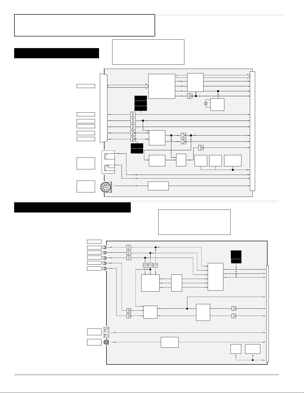
NO PICTURE -2
Troubleshooting
Check the terminal board-DVI.
Check the terminal board-COMPONENT.
Check the Vcc voltages.
S9V (Always)
9V / 5VB / -5V (Switched)
Check the test points.
Check the Vcc voltages.
S9V (Always)
9V / 5VB / -5V (Switched)
Check the test points.
DVI
K80A
DATA
D V I
R
G
B
H
V
K81A
AUDIO
INPUT
CONTROL
PORT
K81B
R
G
B
H
V
AUDIO L
AUDIO R
CONTROL
TP-80R
TP-80G
TP-80B
TP-80H
TP-80V
G-SYNC
H
V
H
Digital
Interface
IC8001
SYNC
SEP.
IC8201
AFC
IC8041
H_DIF
V_DIF
DE_DIF
CLK_DIF
H
V
SW
MOUSE
LATCH
I/OI/O
EXP.
DATA
CPU
I/O
I/O
EXP.
EXP.
EEP
ROM
H_DIF
V_DIF
DE_DIF
CLK_DIF
R
G
B
CS
VS
HS
2
I C
AUDIO L
AUDIO R
CONTROL
INPUT
R/Pr
G/Y
B/Pb
H/HV
V
AUDIO
INPUT
CONTROL
PORT
K10A
R
G
B
H
V
K10B
AUDIO R / L
CONTROL
K10C
ASSY COMPONENT
G-SYNC
H
V
B-Y Y R-Y
BUFFER
IC2001
SYNC
SEP.
IC1051
H
V
MOUSE
CONTROL
FILTER
30MHZ
AFC
IC1061
SW
IC2071
R
TP-2071
TP-2072
G
TP-2073
B
IC1052
IC1053
I/O
EXP.
AUDIO R / L
CONTROL
EEP
ROM
K10H
IIC
R
G
B
CS
HS
VS
-29-
Check the terminal board-AV .
Check the terminal board-DSUB15.
Check the Vcc voltages.
S9V (Always)
9V / 5VB / -5V (Switched)
Check the test points.
Check the Vcc voltages.
S9V (Always)
9V / 5VB / -5V (Switched)
Terminal board DSUB15 does not
exist in some particular models.
VIDEO-Y
S-VIDEO
VIDEO-C
AUDIO INPUT
K131
K131
K101
BNC-Y
K121
S-C
BNC-C
IC141B IC141C
S-Y
SW SW
TP-142
IC141A
SW
AUDIO R
AUDIO L
LPF
SYNC
SEP.
TP-141
C.V.
IC1191
NTSC
PAL
IC1141A
C.V.-C
Y/C-C
3D
Y/C
3LINE
COMB
SW
2
I C
C
NTSC-Y
PAL-Y
NTSC-C
PAL-C
LPF
BPF
IC1141B
SW
IC1141C
SW
TP-5102
TP-5101
LPF
LPF
YY
3D
NR
C
IC5101
Y/C-Y
C.V.-Y
Y/C-Y
NR-Y
NR-Y
NR-C
IC1181C
SW
IC1181B
SW
C.V.-C
IC2161B
IC1181A
SW
BNC-Y
SW
TP-3141
IC2161C
SW
Y/C-C
SW
IC2161A
TP-3142
Cb
YCbCr
Y
YCbCr
DEMOD
IC3141
C
IC2151
SW
DEMATRIX
Cr
IC401
SECAM
DECORDER
DAC
R
G
B
PAL SECAM
I/OI/O
EXP.
ASS'Y AV
BLK
DELAY
EEP
R
G
B
TP-5181
TP-5182
TP-5183
I C
AUDIO R
AUDIO L
R
G
B
2
Timing Chart
INPUT
K131
K71A
R
G
B
H
V
ANALOG_RGB INPUT
I I C
AUDIO
INPUT
CONTROL
PORT
SW
DDC
AUDIO R / L
K72A
CONTROL
K72B
IIC
G-SYNC
H
SYNC
SEP.
V
AFC
H
MOUSE
CONTROL
H
V
SW
I/O
EXP.
K71H
CS
VS
HS
EEP
ROM
AUDIO R / L
CONTROL
D-SUB15
TP5101
TP3141
C
TP5102
TP3142
Y
R
G
B
TP5181
RED
TP5182
GREEN
TP5183
BLUE
IIC
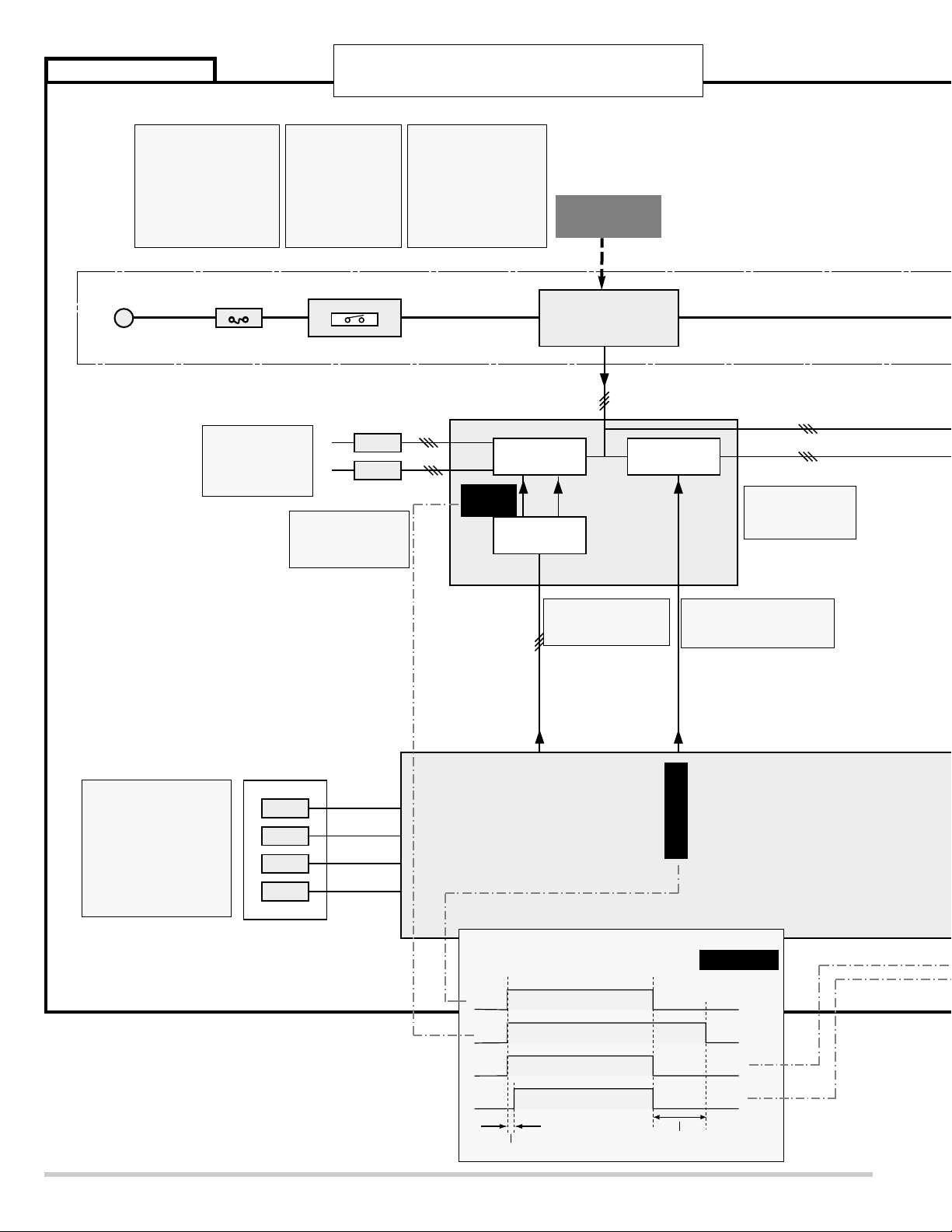
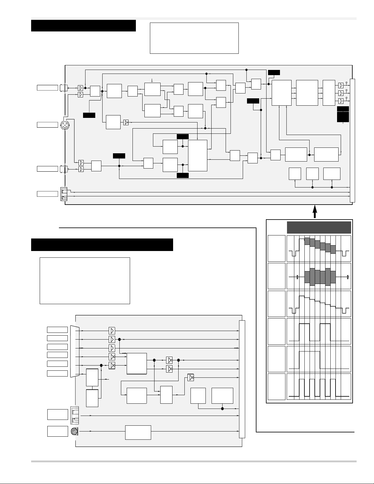
ASS'Y POWER
Hot circuit
AC-INPUT
CPU IC801
and
I / O
EXPANDER
IC1831
SUB POWER
System Control
INTERLOCK SW
FUSE
SW902
F901
DC out
WARNING
TEMP.
READY
POWER-ON/OFF
IIC-SCL & SDA
AC
DC out
I / O
EXPANDER
POWER
CONTROL
SWITCH
INDICATORS
FAN
ON/OFF
FANS
FANS
POWER FAILURE
CONTROL
LAMP
REPLACE
LAMP
Always
Switched
16V /9V /6.25V /-6V
-30-
* NO POWER -1
Troubleshooting
Isn't the lamp cover
of a projector
removed?
When it is removed, the
projector cannot be
turned on.
Is fuse (F901) blown?
Fuse may be opened
when either the LAMP
indicator or the READY
indicator isn't Illuminated.
Check the fuse.
For continued safety,
replace it with a new fuse
of the same type
Is the lamp cover attached
correctly? And has not the
boss(Inner side of the lamp
cover) broken?
Check the boss and the
Interlock switch (SW902).
SW902--open: Abnormality
Are the LAMP
indicator(red) and READY
indicator(green) light?
If the LAMP and READY
indicators are not illuminated, check the primary circuit and S5V of standby
power supply circuit.
Check that the
POWER FAIL signals are correct.
L: Abnormality
Check that the
Vcc-voltages are
correct.
Check that the POWER
ON/OFF signal is correct.
L: Abnormality
Check that the Fan
on/off signal is correct.
L: Abnormality
Check that the IIC
Bus signals for fan
control are correct.
Refer to next
page but one
Power sw
ON
Power on/off
Fan on/off
PFC on/off
Ballast on/off
400~600ms(Stability period of PFC.)
Power sw
OFF
Cooling time after power off.
Timing chart
 Loading...