


Sanyo PLC-SU20B Service Manual
Multimedia Projector
SERVICE MANUAL
PRODUCT CODE
(PA6A) PLC-SU20E: 1 122 068 00
(PA6C) PLC-SU20B: 1 122 068 02
Original Ver sion
REFERENCE NO.SM5110048
FILE NO.
Model No. PLC-SU20E
(Europe, Asia, Africa,
M.E.)
PLC-SU20B
(U.K.)
Give complete “Service Ref. No.” for parts
order or servicing, it is shown on the rating
sheet on the projector.
Service Ref. No.: PLC-SU20E-00
PLC-SU20B-00

2
■ Contents
■ Safety instructions ________________________________________________3
■ Specifications __________________________________________________ 4
■ Adjustments after parts replacement ________________________________ 5
■ Circuit protections ______________________________________________ 6-7
Fuse ______________________________________________________ 6
Thermal switch ______________________________________________ 7
Warning temperature and power failure protection____________________ 7
■ Mechanical disassemblies ______________________________________ 8-13
■ Optical parts disassemblies ____________________________________ 14-18
■ LCD panel replacement __________________________________________ 19
■ Lamp replacement____________________________________________ 20-22
■ Optical adjustments __________________________________________ 23-25
● Convergence adjustment ____________________________________ 23
● Contrast adjustment ________________________________________ 24
● Integrator lens adjustment __________________________________ 25
■ Electric adjustments __________________________________________ 26-35
● Service adjustment menu operation____________________________ 26
● Circuit adjustments ______________________________________ 27-32
● Service adjustment data table______________________________ 33-34
● Test points and locations ____________________________________ 35
■ Troubleshooting ______________________________________________ 36-40
● No power______________________________________________ 36-38
● No picture ________________________________________________ 39
● No sound ________________________________________________ 40
■ Control port functions ________________________________________ 41-42
■ Waveforms__________________________________________________ 43-45
■ Cleaning ______________________________________________________ 46
■ IC block diagrams ____________________________________________ 47-58
■ Pins description of ICs, transistors, diodes____________________________ 59
■ Parts description in schematic diagram ______________________________ 60
■ Service parts lists ____________________________________________ 61-87
● Electrical parts list ______________________________________ 61-81
● Mechanical parts list ____________________________________ 82-87
■ Circuit block diagram ____________________________________________ A1
■ Power supply lines ______________________________________________ A2
■ Schematic diagrams__________________________________________ A3-A9
■ Printed wiring board diagrams ________________________________ A10-A12
3
WARNING:
The chassis of this projector is isolated (COLD) from AC line by using the converter transformer.Primary side of
the converter and lamp power supply unit circuit is connected to the AC line and it is hot, which hot circuit is iden-
tified with the line ( ) in the schematic diagram. For continued product safety and protection of personnel
injury, servicing should be made with qualified personnel.
The following precautions must be observed.
■ Safety Instructions
SAFETY PRECAUTIONS
1: An isolation transformer should be connected in the
power line between the projector and the AC line
before any service is performed on the projector.
2: Comply with all caution and safety-related notes pro-
vided on the cabinet back, cabinet bottom, inside the
cabinet or on the chassis.
3: When replacing a chassis in the cabinet, always be
certain that all the protective devices are installed
properly, such as, control knobs, adjustment covers
or shields, barriers, etc.
DO NOT OPERATE THIS PROJECTOR WITHOUT
THE PROTECTIVE SHIELD IN POSITION AND
PROPERLY SECURED.
4: Before replacing the cabinet cover, thoroughly
inspect the inside of the cabinet to see that no stray
parts or tools have been left inside.
Before returning any projector to the customer, the
service personnel must be sure it is completely safe to
operate without danger of electric shock.
SERVICE PERSONNEL WARNING
Eye damage may result from directly viewing the light produced by the Lamp used in this equipment. Always turn
off Lamp before opening cover.The Ultraviolet radiation eye protection required during this servicing.
Never turn the power on without the lamp to avoid electric-shock or damage of the devices since the stabilizer
generates high voltages(15kV - 25kV) at its starts.
Since the lamp is very high temperature during units operation replacement of the lamp should be done at least
45 minutes after the power has been turned off, to allow the lamp cool-off.
PRODUCT SAFETY NOTICE
Product safety should be considered when a component replacement is made in any area of the projector.
Components indicated by mark in the parts list and the schematic diagram designate components in which
safety can be of special significance.It is, therefore, particularly recommended that the replacement of there parts
must be made by exactly the same parts.
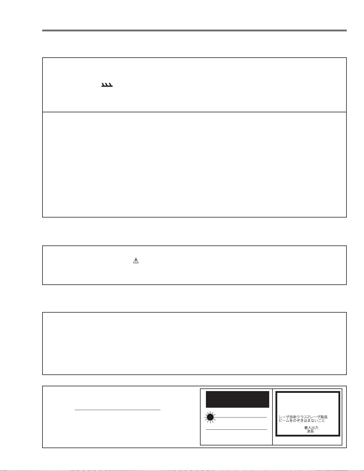
DO NOT A TTEMPT T O SERVICING THE
REMOTE CONTROL UNIT.
Laser Beam may be leaked out when in disassemble
the Unit. As the Laser Beam used in this Remote con-
trol unit is harmful to the eyes.
LASER RADIATION
DO NOT STARE INTO BEAM
MAX. OUTPUT: 1mW
WAVE LENGTH: 650±20nm
CLASS II LASER PRODUCT
This product is complied with 21 CFR
part 1040.10
CAUTION
LASER RADIATION
DO NOT STARE INTO BEAM
CLASS 2 LASER PRODUCT
LASER-STRAHLING
NICHT IN DEN STRAHL BLICKEN
LASER KLASSE 2
IEC60825-1, Am. 1 1997
MAX OUTPUT ( ) : 1 mW
WAVE LENGTH ( ) : 650±20nm
4
Projector Type Multi-media Projector
Dimensions (W x H x D) 239mm x 90mm x 323mm
Net Weight 3.9kg
LCD Panel System 0.9” TFT Active Matrix type, 3 panels
Panel Resolution 800 x 600 dots
Number of Pixels 1,440,000 (800 x 600 x 3 panels)
Color System 6 color system (PAL, SECAM, NTSC, NTSC4.43, PAL-M and PAL-N)
Scanning Frequency H-sync. 15 ~ 80kHz, V-sync. 50 ~ 100Hz
Projection Image Size (diagonal) Adjustable from 30” to 300”
Horizontal Resolution 750 TV lines
Projection Lens F1.7 ~ 2.0 lens with f33.2mm ~ 43.1mm Motor zoom and focus
Throw Distance 1.4m ~ 10.8m
Projection Lamp 150watt type
AV Input Jacks RCA Type x 1 (Video, Audio R and L) and DIN 4 pin (S-Video) x 1
Computer Input Jack (VGA) HDB15 Terminal x 1
Control Port Jack DIN 8 pin x 1
Monitor Output Jack (VGA) HDB15 Terminal x 1
Computer Audio Input Jack Mini Jack (stereo)
Audio Output Jack Mini Jack (stereo)
Internal Audio Amp. 1W RMS (monaural)
Built-in Speaker 1 speaker, 40mm x 30mm
Feet Adjustment 0˚ to 10˚
Voltage AC 200 ~ 240V, 50/60Hz
Power Consumption 1.4A (Max. Ampere)
Operating Temperature 5˚C ~ 35˚C
Storage Temperature -10˚C ~ 60˚C
Remote Control Transmitters Wireless Remote Control with Laser Beam (Class II Laser)
Max. Output 1mW/Wave length 650 ±20nm, batteries (2) AA type.
■ Specifications
● The specifications are subject to change without notice.
5
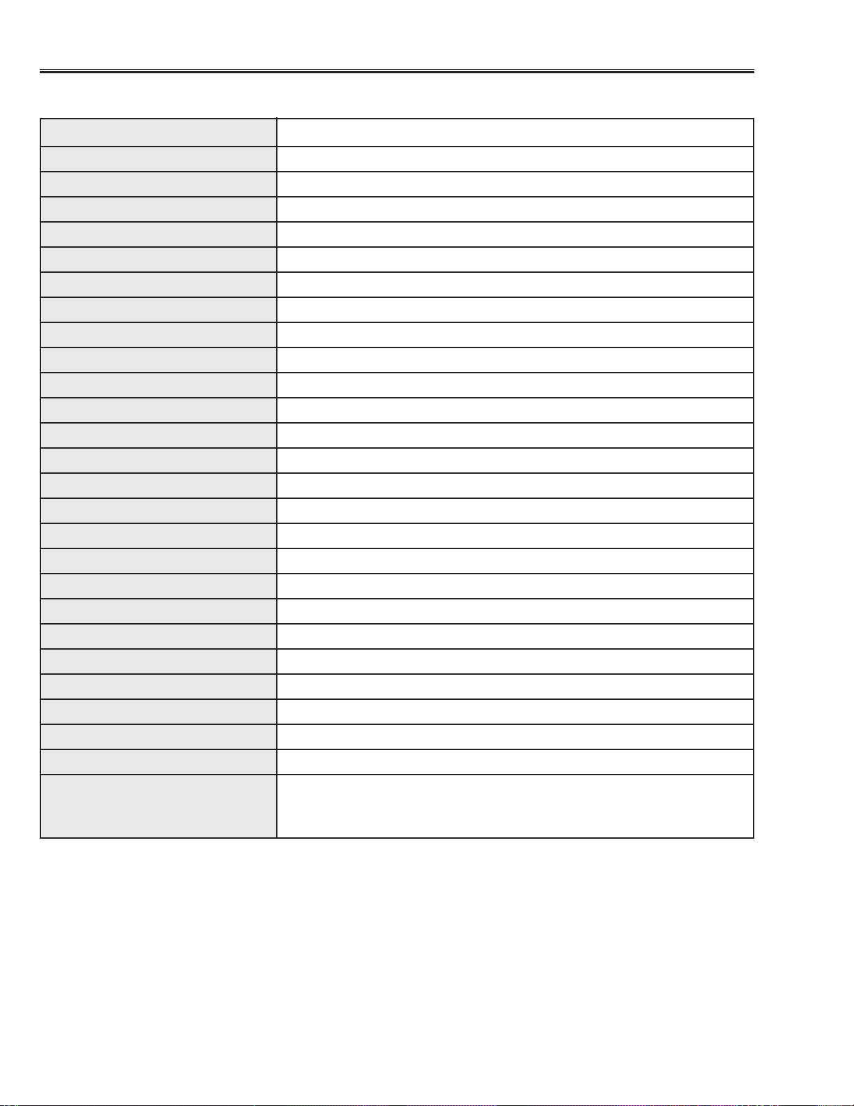
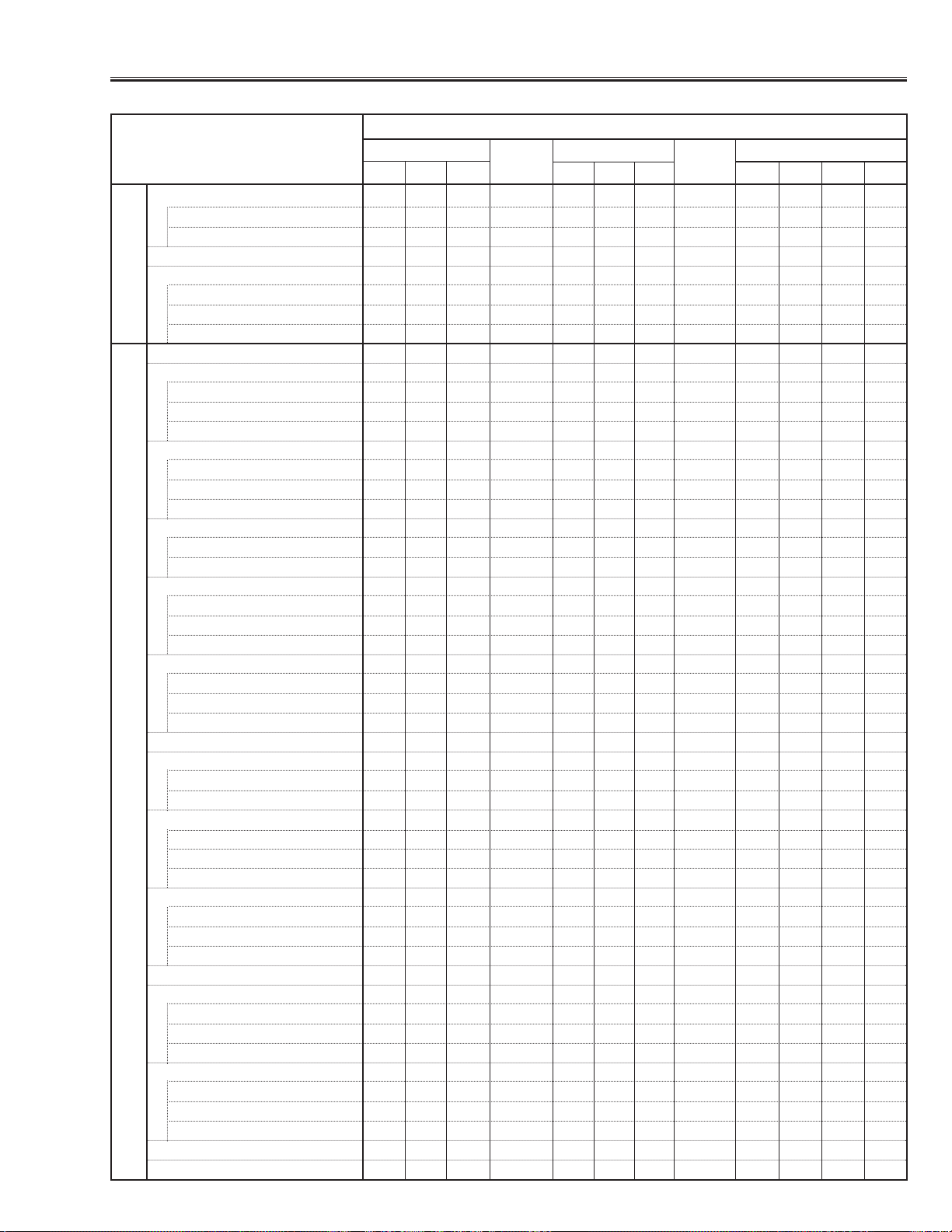
■ Adjustments after Par ts Replacement
Convergence Adjustment
R-Convergence adjustment ●●
B-Convergence adjustment ●●
Integrator Lens Adjustment ●
Contrast Adjustment
R-Contrast adjustment ●
G-Contrast adjustment ●
B-Contrast adjustment ●
Output voltage adjustment ●
Pedestal adjustment
R-pedestal adjustment ●
G-pedestal adjustment ●
B-pedestal adjustment ●
Offset adjustment
R-offset adjustment ●
G-offset adjustment ●
B-offset adjustment ●
Video gain adjustment-[CG/MCI]
CG-video gain adjustment ●
MCI-video gain adjustment ●
Video gain adjustment-[AV]
R-video gain adjustment ●
G-video gain adjustment ●
B-video gain adjustment ●
Video center adjustment
R-video center adjustment ●●
G-video center adjustment ●●
B-video center adjustment ●●
NRS Adjustment ●●
Gamma off video adjustment
CG-gamma off video adjustment ●●
AV-gamma off video adjustment ●●
CG/MCI/AV-video adjustment-1 ▲▲▲
CG-video adjustment ●●
R-video adjustment ●●
B-video adjustment ●●
CG/MCI/AV-video adjustment-2
CG-video adjustment ●●
MCI-video adjustment ●●
AV-video adjustment ●●
S/H clock adjustment ●●
Common center adjustment
R-common center adjustment ● ●●
G-common center adjustment ●●●
B-common center adjustment ●●●
White balance adjustment
CG-white balance adjustment ❍❍❍ ❍❍❍
MCI-white balance adjustment ❍❍❍ ❍ ❍❍
AV-white balance adjustment ❍❍❍ ❍ ❍❍
Black balance adjustment ❍❍❍ ❍❍❍
White Uniformity Adjustment ❍❍❍ ❍ ❍❍
Disassembly / Replaced Part
LCD Panel
RG B
Integrator
lens
Polarized glass
RGB
Main Comp.Board
ABCD
Optical AdjustmentsElectrical Adjustments
● : Adjustment necessary ❍ : Check necessary ▲ : Specified adjustment necessar y see LCD Panel Replacement
P.F. C
Board
-6-
■ Circuit Protections
This projector is equipped with the following circuit protections to operate in safety. If the abnormality occurs inside
the projector, it will automatically turn off by operating one of the following protection circuits.
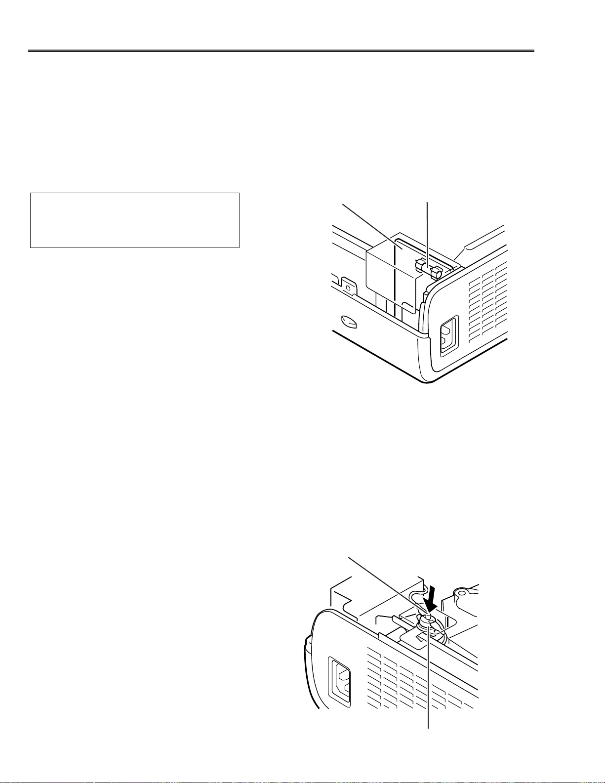
Fuse
The fuse is located inside of the projector.When either the LAMP indicator or the READY indicator is not illuminat-
ed, fuse may be opened. Check the fuse as following steps.
It should be used the specified fuse as follows;
How to replace the fuse
1. Remove the cabinet top following to “Mechanical
Disassemblies”.
2. Remove the fuse from fuse holder.
To install the fuse, take reversed step in the above.
Fuse Part No.: 423 022 2102
TYPE T4.0AH 250V FUSE
LITTLE FUSE INC.TYPE 215004
Fuse
Line Filter Board
Thermal switch
There is the thermal switch (SW902) inside of the projector to prevent the internal temperature from rising abnor-
mally. When the inter nal temperature reaches near 100˚C, turn off the AC main power supply automatically.
The thermal switch is not reset to normal automatically even if the internal temperature becomes normal. Reset the
thermal switch following procedure.
Check the resistance between terminals of thermal switch by using the tester. If it has high impedance, thermal
switch may be in operative.
How to reset the thermal switch
1. Remove the cabinet top following to “Mechanical
Disassemblies”.
2. Press the reset button on the thermal switch.
CAUTION:
Before press the reset button, disconnect the AC cord from
the projector.
Thermal switch (SW902)
Reset Button
-7-
Circuit Protections
Warning temperature and power failure protection
The TEMP WARNING indicator flashes red and the projector will automatically turn off when the internal tempera-
ture of the projector exceeds the normal temperature or when stopping cooling fans or when the internal power sup-
ply lines are failed.
Check the following possible causes and wait until stopping the TEMP WARNING indicator flashing.
Possible causes
- Air filter is clogged with dust particles. Remove dust from the air filter by following instructions in the “Air filter care
and cleaning” below.
- Ventilation slots of the projector are blocked. In such an event, reposition the projector so that ventilation slots are
not obstructed.
- Check if projector is used at higher temperature place (Normal operating temperature is 5 to 35 ˚C)
If the TEMP WARNING indicator still continues to flash, there may be defects on cooling fans or power supply cir-
cuits. Please check fan operation and power supply lines referring to the “Power Supply Lines Chart”.
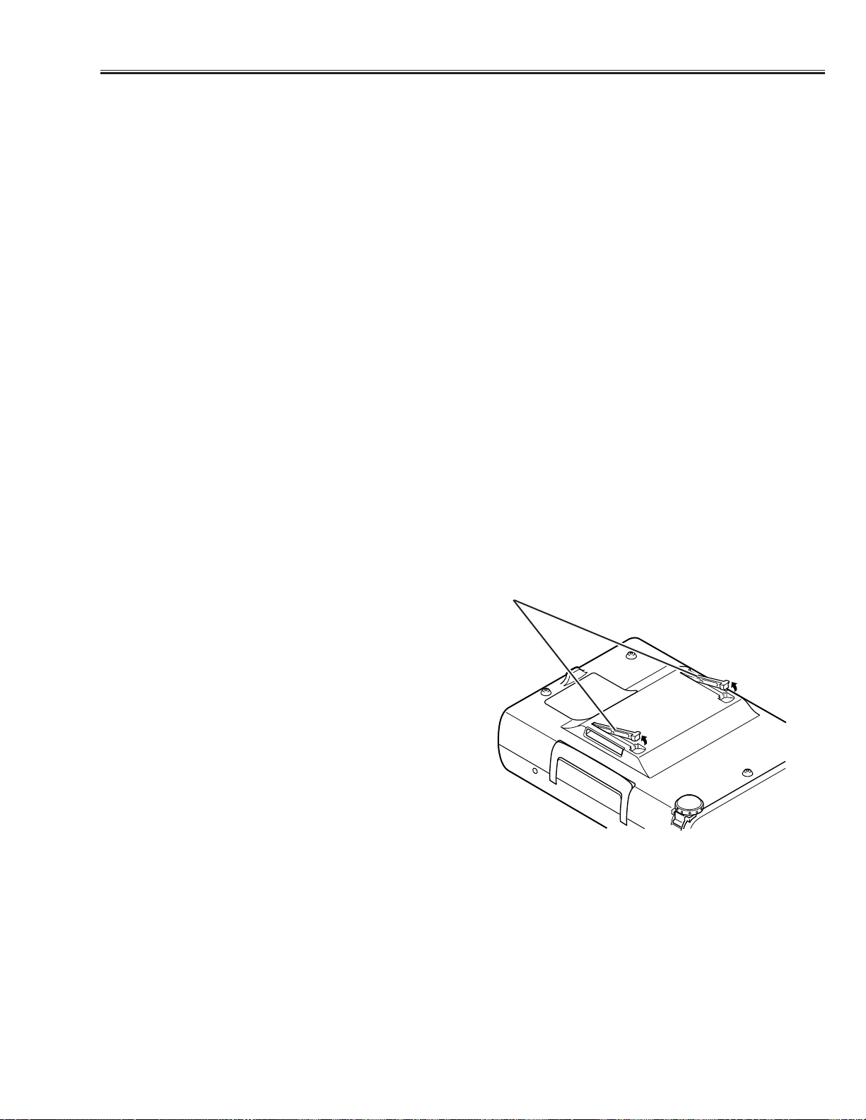
Air filter care and cleaning
The removable air filters prevents dust from accumulation on the surface of the projection lens and projection mirror.
Should be the air filter become clogged with dust particles, it will reduce the cooling fan’s effectiveness and may
result in internal heat build up and reduce the life of the projector.
To clean up the air filters, follow the cleaning procedure
below:
1.Turn the power off, and disconnect the AC po w er cord
from the AC outlet.
2. Tur n the projector up side down and remove 2 air fil-
ters by pulling the latches of them upward.
3. Clean the air filters with brush or wash out the dust
and particles.
4. Replace the air filter.Make sure that the air filters are
fully inserted.
CAUTION:
Do not operate the projector with the air filter removed.
The dust is stuck on the LCD panel and the mirror, and
it may spoil the fine picture image.
Do not put the small parts into the air filter intake vents.
It result in the malfunction of the projector.The air filter
is small parts. Take care that children don’t eat or swal-
low it.
RECOMMENDATION
We recommend to avoid dusty, smoky place for operating the projector. Using in dusty place may cause the picture
of poor quality.
When using under the dusty or smoky conditions, dust may accumulate on the LCD panel and lens inside it, and
may resultantly be projected on the screen together with the picture.
When the above symptoms are noticed, please clean up the LCD panel and lens f ollowing to the “Cleaning Method”.
Air filters
-8-
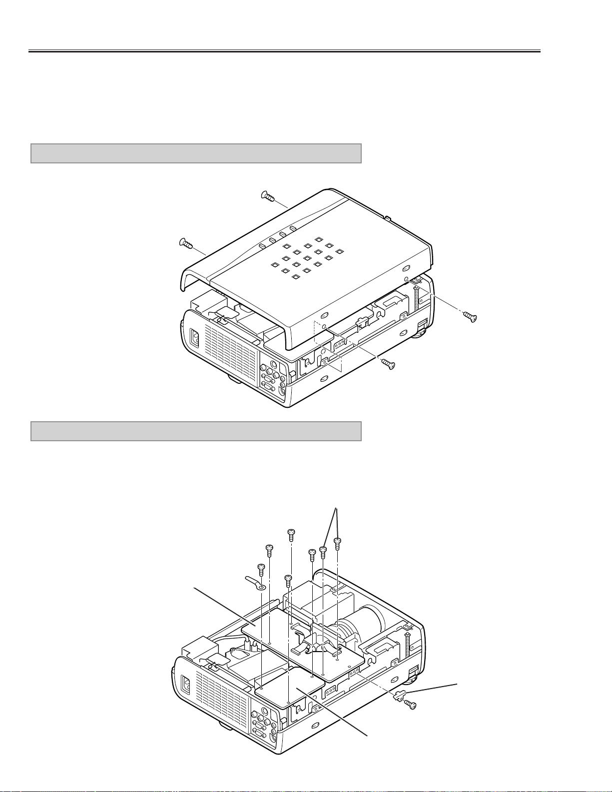
Remove 4 screws and pull cabinet top upward.
1. CABINET TOP REMOVAL
■ Mechanical Disassemblies
Mechanical disassemble should be made following procedures in numerical order.
Following steps show the basic procedures, therefore unnecessary step may be ignored.
Caution:
The parts and screws should be placed exactly the same position as the original otherwise it may cause loss of
performance and product safety.
Fig.1
1) Remove 3 screws (A) and take the AV SUB Board off upward.
2) Remove a screw (B) and a fixer, then disconnect the FPC cables.
3) Remove 4 screws (C) and pull the Main-B/C Boards off upward.
2. AV SUB, MAIN-B/C BOARD REMOVAL
Fig.2
C
C
C
A
A
A
B
Fixer
AV SUB Board
Main-B/C Board
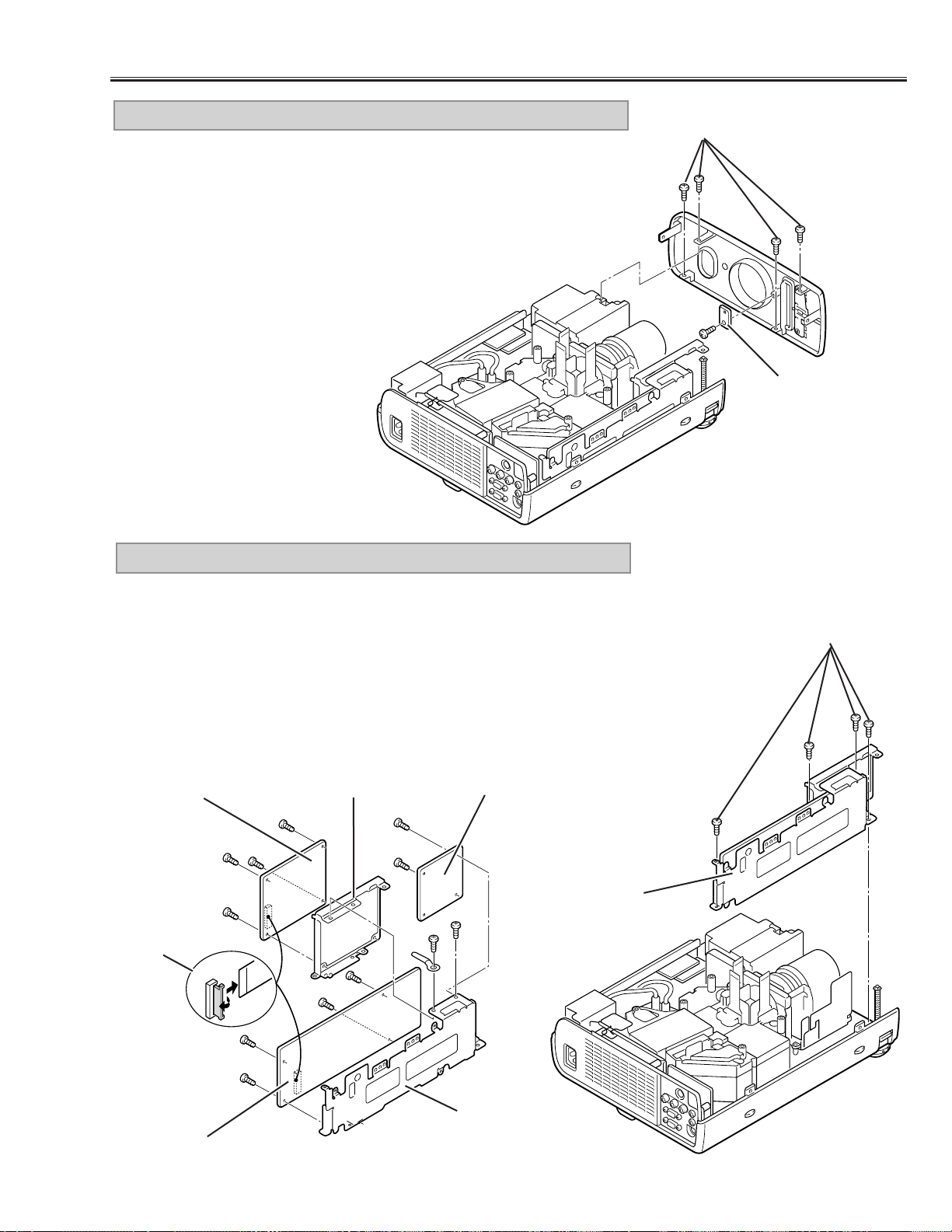
1) Remove 4 screws (A) and pull the Viewer and Main-A/D Board Ass’y
upward.
2) Remove 2 screws (B) and disconnect connector K1A, then take the
Viewer Board Ass’y off from the Main-A/D Board Ass’y.
3) Remove 4 screws (C) and take the Viewer Unit off from the Viewer
Mounting Holder.
4) Remove 2 screws (D) and remove the Main-D Board.
5) Remove 4 screws (E) and take the Main-A Board off from the Main-A
Board Holder.
4.VIEWER*, MAIN-A/D BOARD REMOVAL
-9-
Mechanical Disassemblies
1) Remove 4 screws (A) and remove the front cabinet forward.
2) Remove a screw (B) and remove the Viewer LED Board.
* Model without the PC Card slot does not provide the Vierwer Board.
3. FRONT CABINET, VIEWER LED BOARD* REMOVAL
Fig.3
A
A
Fig.4
Fig.5
D
D
B
B
E
E
E
E
C
C
C
C
Viewer Board *
Main-D Board
K1A
Main-A Board
Viewer, Main-
A/D Ass’y
Main-A Board
Holder
Viewer Board Holder
B
Viewer LED
Board *
* Model without the PC Card slot does not
provide the Vierwer Board.
-10-
Mechanical Disassemblies
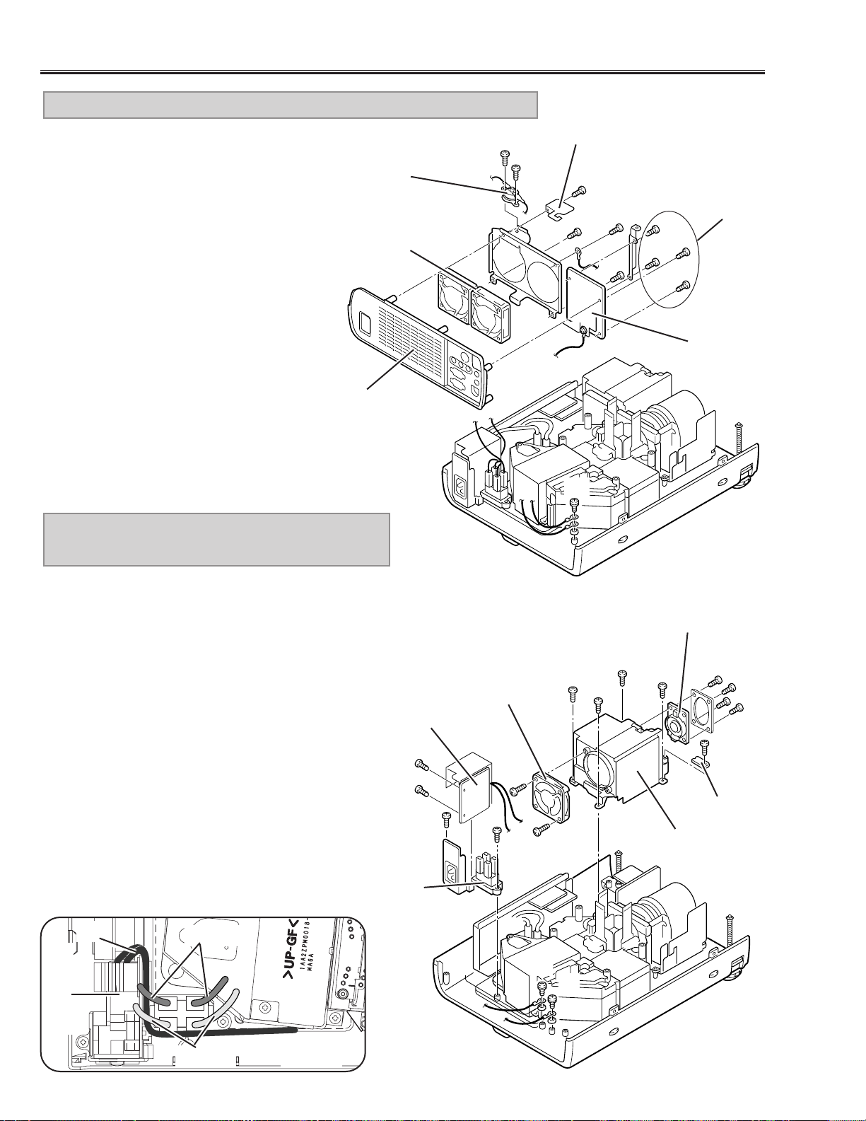
1) Pull the Rear Cabinet Ass’y upward.
2) Remove a screw (A) and take the
spacer off.
3) Remove 2 screws (B) and remove the
Thermal Switch (SW902).
4) Remove a screw (C) and remove the
grounding lead.
5) Remove 4 screws (D) and remove the
AV Board.
6) Remove 4 screws (E) and remove the
fans (FN904, FN905).
5. AV BOARD, REAR CABINET, FAN (FN904, FN905) REMOVAL
a
a
b
b
c
c
d
d
Fig.6
C
D
B
B
E
E
A
E
Rear Cabinet
Fan
(FN904, FN905)
Thermal Switch
(SW902)
Spacer
AV Board
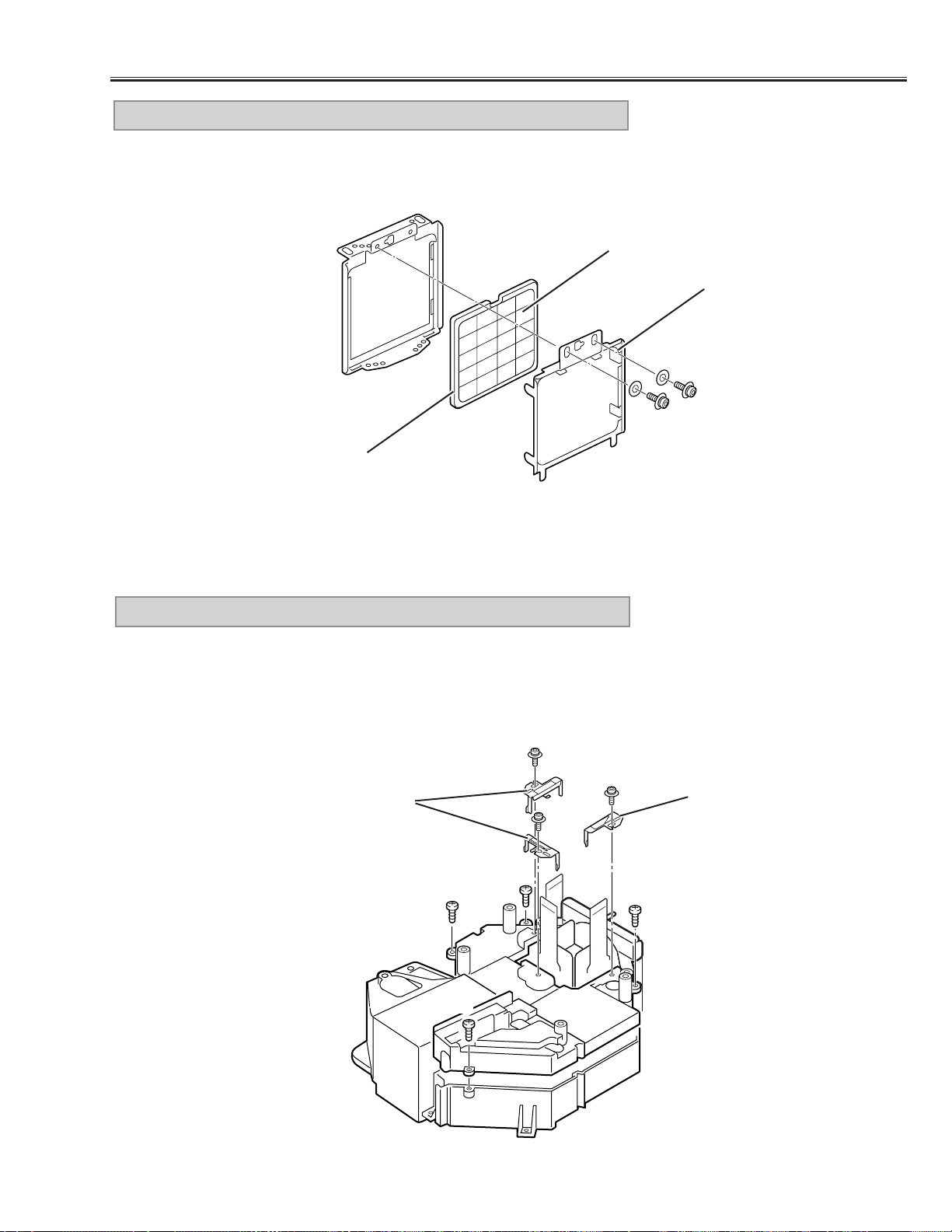
1) Remove 4 screws (A) and remove the Power Cover.
2) Remove 2 screws (B) and remove the Fan (FN901).
3) Remove 4 screws (C) and remove the Speaker.
4) Remove a screw (D) and remove R/C Board.
5) Remove 2 screws (E) and remove the grounding
leads.
6) Remove 2 screws (F) and pull the Filter & Interlock
Switch Ass’y.
7) Remove 2 screws (G) and then remove the Filter
Board and the Interlock Switch Ass’y.
Note:
* When fixing the grounding lead of the Filter Board,
disconnect the lamp socket (refer to Fig.8) first, and
fix the grounding lead then connect the lamp socket.
* Dress the grounding lead (e), (f) as show in Fig.7-2.
* Make sure of wires color as shown in Fig.7-2 when
connecting the sockets.
6. POWER COVER, FAN (FN901), FILTER
BOARD REMOVAL
e
e
f
f
C
A
A
A
C
A
E
R/C Board
Speaker
(SP901)
Power Cover
Fan(FN901)
D
B
B
F
E
Interlock Switch
(SW904)
F
G
G
Filter Board
Filter Board
Blue
Brown
Fig.7-1Fig.7-2
C
e, f
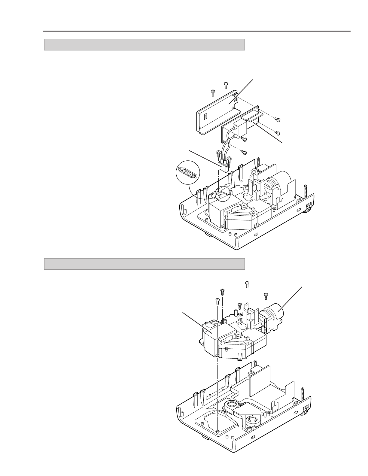
1) Remove 2 screws (A) and disconnect the lamp socket.
2) Remove 2 screws (B) and pull the Lamp Ballast Ass’y upward.
3) Remove 2 screws (C) and remove the Lamp Ballast Unit from
the Lamp Ballast Holder.
7. LAMP BALLAST UNIT REMOVAL
-11-
Mechanical Disassemblies
Fig.8
C
B
B
C
C
A
C
Lamp Socket
Lamp Ballast Holder
Lamp Ballast Unit
A
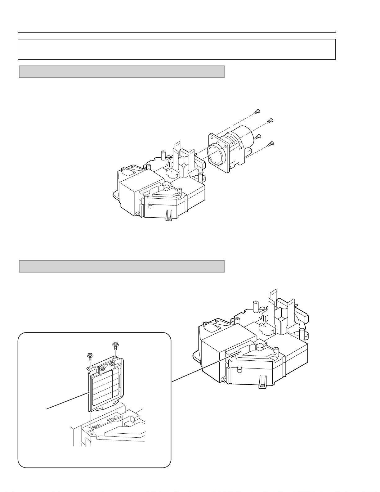
1) Remove 5 screws and pull the Optical Unit upward.
8. LENS, OPTICAL UNIT REMOVAL
Fig.9
Lens
Optical Unit
-12-
Mechanical Disassemblies
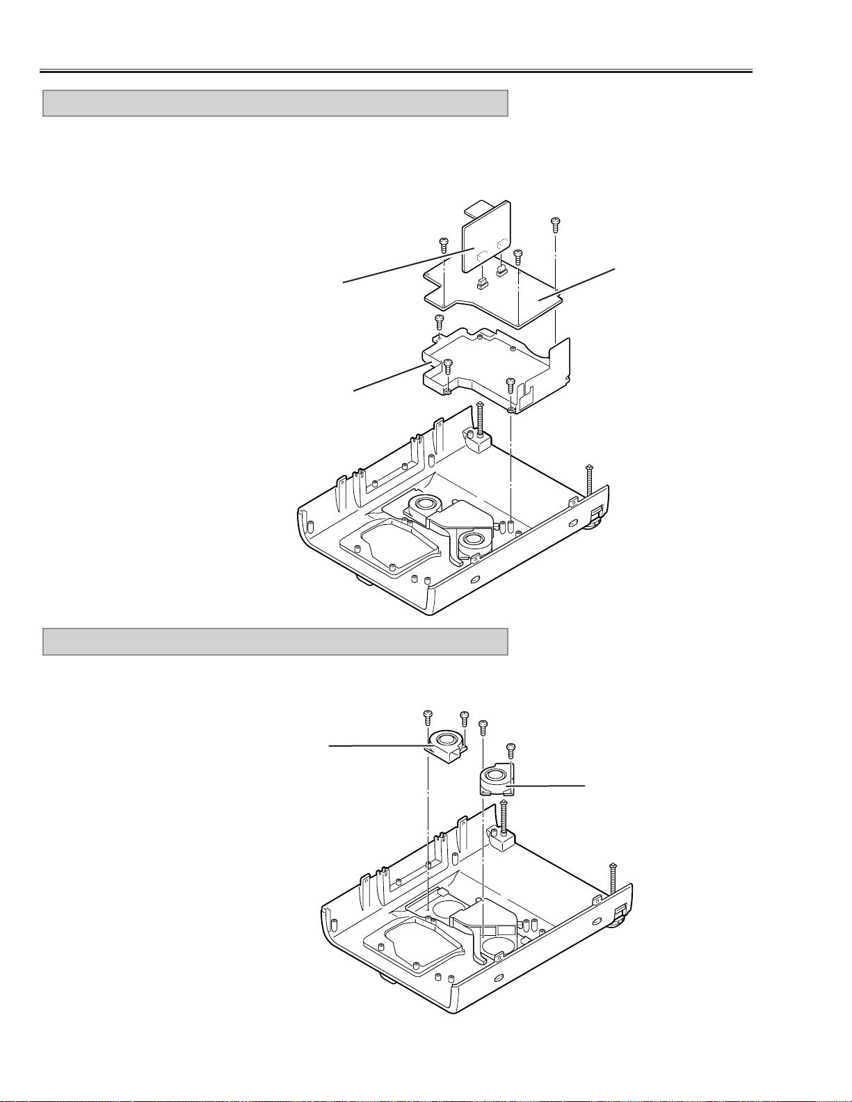
1) Remove screws (A) and pull the Power Board Ass’y upward.
2) Remove 3 screws (B) and take the Power Board off from the Power Board
Holder.
3) Remove the P.F.Board from the Power Board.
9. POWER, P.F. BOARD REMOVAL
Fig.10
Power Board
P.F. Board
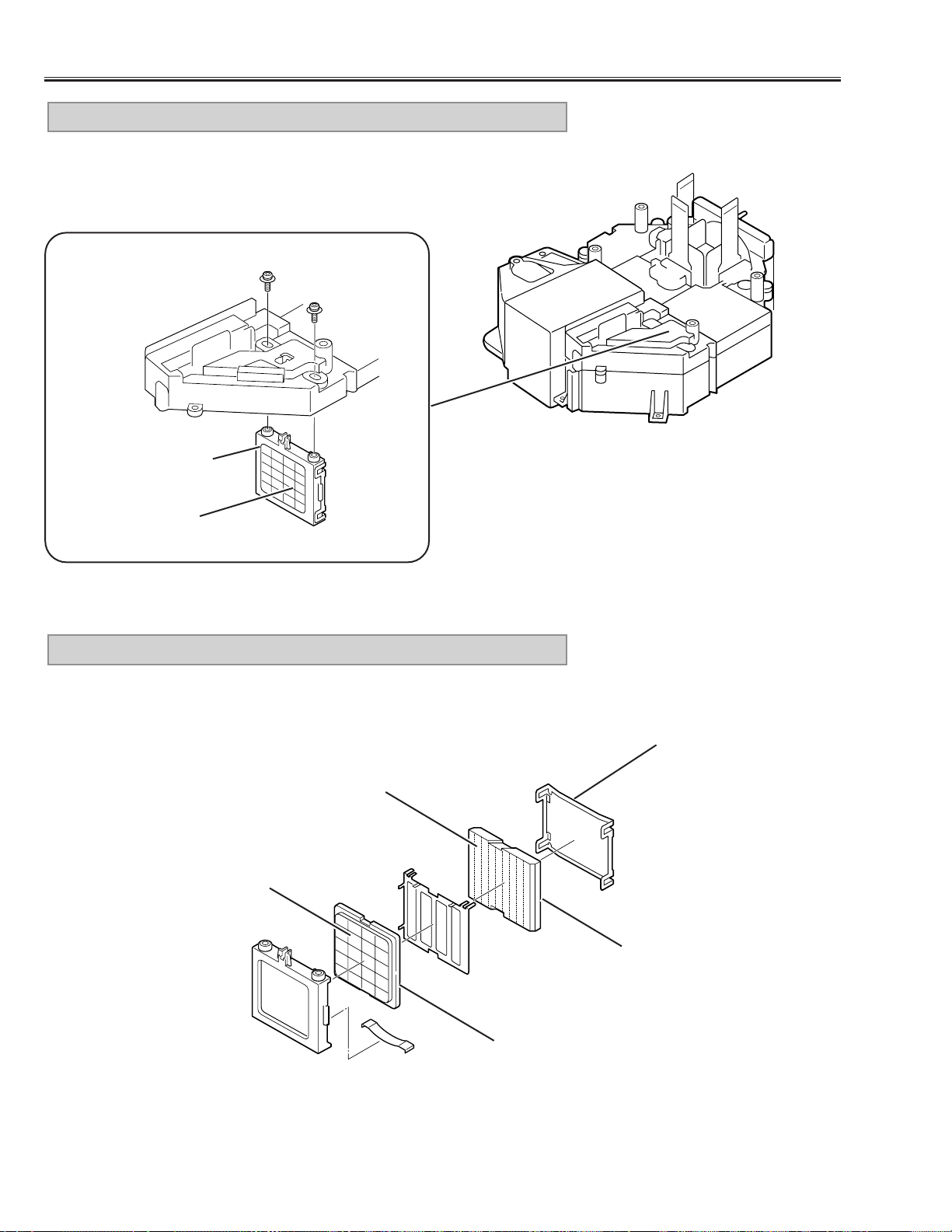
1) Remove each 2 screws and take the Fans (FN902, FN903) off.
10. FAN (FN902, FN903) REMOVAL
Fig.11
Fan (FN902)
Fan (FN903)
P.F. Board Holder
A
A
A
B
B
B
-13-
Mechanical Disassemblies
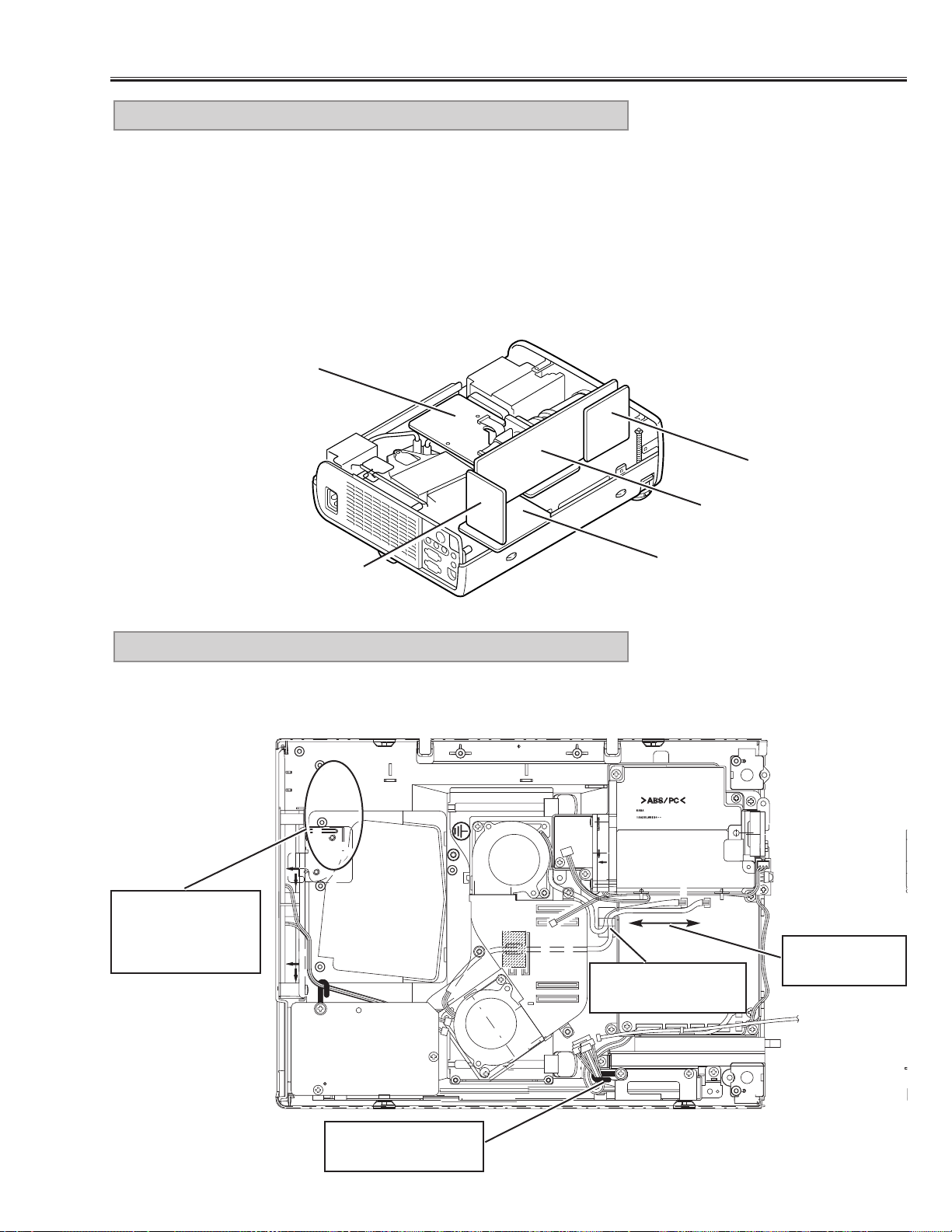
For servicing the A V, A V Sub, Main-A and Main-D Board, it is advisable to set
up the service position for the checking and testing easily following to below
steps
1) Remove the AV, AV Sub and Main-A/D Board following to steps 1~5 of
“Mechanical Disassemblies”.
* Should be remove the Main-A Board Holder and Viewer Holder.
2) Mount the AV, AV Sub, and Main-A/D Board to the Main-B Board.
* Not necessary to connect the Viewer Board.
Note:
In the mounting, make sure of the mounting direction of connectors.
11. SERVICE POSITION
Fig.12
Main-D Board
Main-B Board
AV Board
Main-A Board
AV Sub Board
Make sure to dress the lead wires as follows when assembling the chassis
and cabinets
12. LEAD WIRE DRESSING
Fig.13
AV Sub Board
Do not loosen
these wires
Use a fixer for dress-
ing these wires.
Fix wires firmly after
dressing.
Make sure that the
wires around here
are dressed not to
touch to the fans.
-14-
1) Remove the Optical Unit/Projection Lens following to the step 8 of
“Mechanical Disassemblies”.
2) Remove 4 screws and remove the Projection Lens.
1. PROJECTION LENS REMOVAL
Remove 2 screws (A) and pull the Integrator Lens-IN Ass’y upward.
2. INTEGRATOR LENS-IN ASS’Y REMOVAL
Fig.2
Fig.1
■ Optical Par ts Disassemblies
Remove the Cabinet Top , AV Sub, Main-B/C Board following to the “Mechanical Disassemblies”, before proceed-
ing these disassemblies.
A
A
Integrator Lens-IN
Ass’y
Fig.3
-15-
Remove 2 screws (A) and take the Integrator Lens-IN off from the lens
holder.
3. INTEGRATOR LENS-IN ASS’Y DISASSEMBLY
1) Remove each screw (A) and remove the Polarized Glass Holders.
2) Remove 4 screws (B) and take the Optical Unit Top off.
4. OPTICAL UNIT TOP REMOVAL
A
A
Lens Holder
Lens Surface
Integrator Lens-IN
Fig.4
Fig.5
Optical Pats Disassemblies
A
A
A
B
B
B
B
Polarized Glass Holder
Polarized Glass Holder
-16-
Optical Parts Disassemblies
Remove 2 screws (A) and pull the Integrator Lens-OUT Ass’y downward.
5. INTEGRATOR LENS-OUT ASS’Y REMOVAL
Integrator Lens-OUT
Ass’y
Lens Surface
A
A
Fig.7
Fig.6
Remove the Lens Holder and disassembly the Integrator Lens-OUT Ass’y.
6. INTEGRATOR LENS-OUT ASS’Y DISASSEMBLY
Lens Holder
Prism Assy
(Beam Splitter)
Fig.8
Lens Surface
Integrator Lens-OUT
Surface attached the
phase sheet comes to
the lens holder.
-17-
Optical Parts Disassemblies
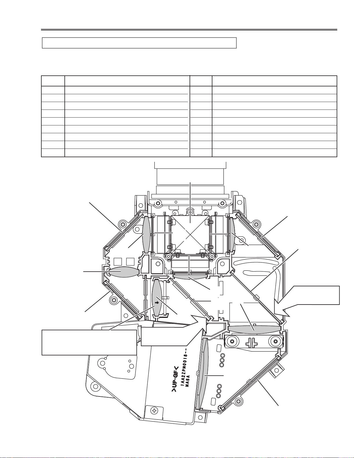
When the optical parts mounting or assembling, the parts must be mounted
in the specified location and direction. Please refer to the figure below and
“Mounting direction of optical parts” on next page.
1 Prism ass’y
2 Relay lens (IN)
3 Relay lens (OUT)
4 Condenser lens (IN)
5 Condenser lens (OUT)
6 Condenser lens
7 Condenser lens (B)
8 Mirror (W)
9 Mirror (R)
10 Mirror (B)
11 Optical Filter (UV cut)
12 Polarized glass (R-filter)
13 Polarized glass (IN/G)
14 Polarized glass (IN/B)
15 Dichroic mirror (R)
16 Dichroic mirror (G)
No. Part name No. Part name
1
3
2
4
5
6
7
13
14
8
12
Parts Name and Locations
11
16
15
Fig.9
10
9
10
6
Printed marker
comes this side
Printed marker
comes this side
Mount lens to be the same direc-
tion of the arrow marker on both of
the lens and optical base bottom.

-18-
Optical Parts Disassemblies
The optical parts must be mounted in specified direction otherwise the picture image will not reproduce correctly.
● Mounting direction of Lens (Key No. 2, 3, 4, 5, 6, 7)
Lens (Key No. 2) is mounted as shown in Fig.9.
Lens (Key No. 3, 7) have no specified mounting direction.
Lens (Key No. 4, 5, 6,) are mounted as shown in Fig.9.
● Mounting direction of Mirrors (Key No. 8, 9, 10)
Mount the mirrors as the coating surface comes inside.
● Mounting direction of optical filter (Key No. 11)
The optical filter has no specified mounting direction.
● Mounting direction of polarized glasses (Key No. 2, 13, 14)
Mount each polarized glass as the face that the polarized film is attached comes the prism ass’y.
● Mounting direction of dichroic mirror (Key No. 15,16)
dichroic mirrors are mounted as shown in Fig.9.
Mounting direction of optical parts
-19-
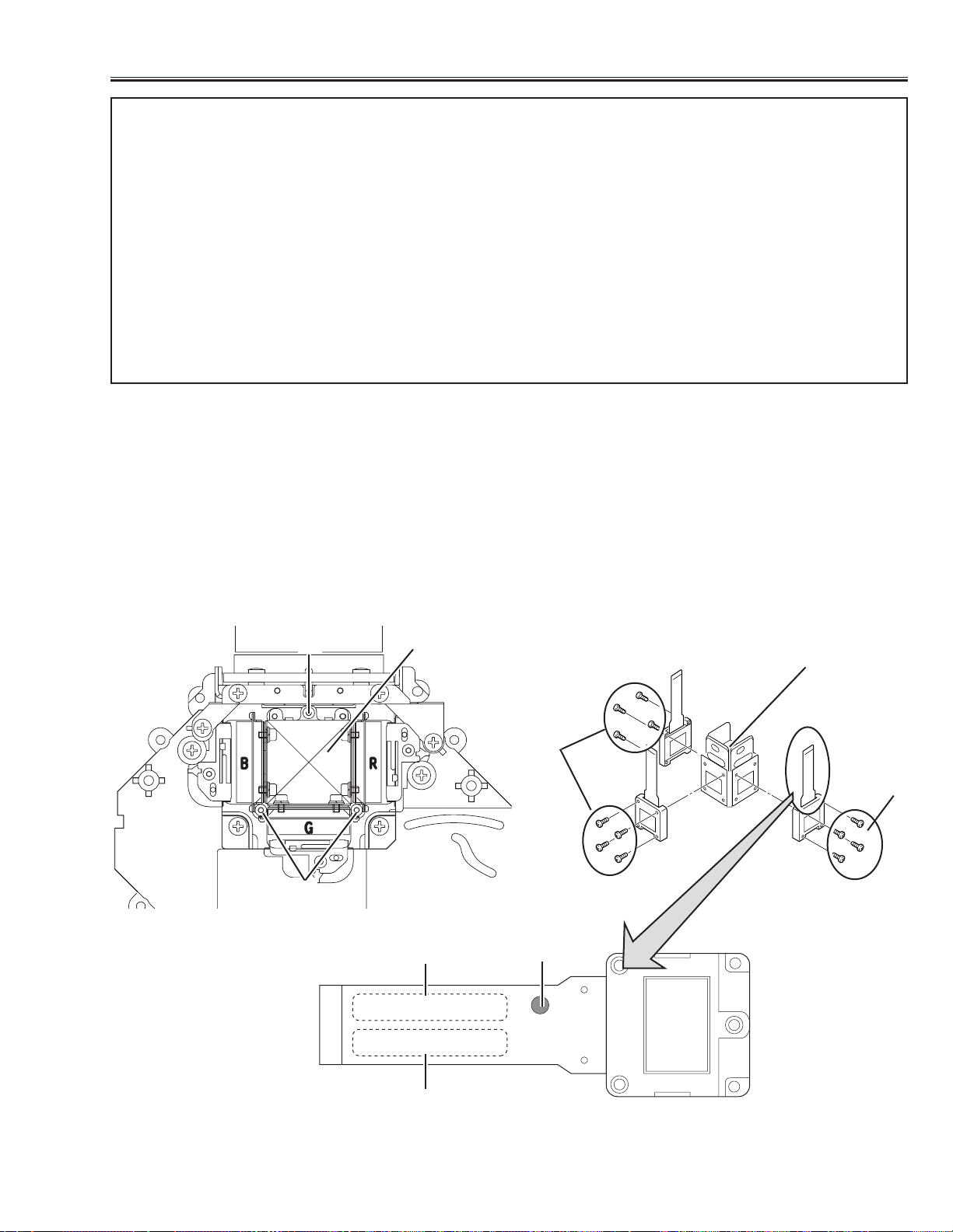
■ LCD Panel Replacement
● LCD PANEL REMOVAL
1. Remove the cabinet top following to “Mechanical Disassemblies”.
2. Remove 3 screws (A) by using 2.0mm hex driver, and then pull the prism/panel ass’y out from the optical base.
3. Remove 4 screws (B) to take off the LCD panel from the prism/panel ass’y.
Caution: Do not remove 3 panels (R,G,B) at the same time as it is necessary the standard panel for adjustment.
Do not fasten the screws with excessive force when mounting the LCD panel, otherwise focus adjust-
ment may be shifted.
A
A
B
B
Prism Ass’y
B-LCD Panel
G-LCD
Panel
R-LCD
Panel
SEAL
PART NO.
LOT NO.
Prism Ass’y
P09SG210
1-A-1234A9
IMPORTANT NOTICE on LCD Panel Replacement
There are 2 types (Type A, Type B listed on next page) of LCD panels which they have a different character istics
used for this model. As the only Type B LCD panels are supplied for the service spare parts, take care the follow-
ing notice when the LCD panel replacement.
1.When replacing the LCD panel, confirm the indication of the LCD panel, then replace the correct LCD panel.
Select either combination (1) or (2) listed on next page when in combine the R, G and B LCD panel, please
see the explanation “COMBINATION OF LCD PANELS”.
2. After replacing LCD panel, the specified adjustment [Video Adjustment] should be performed for obtaining bet-
ter performance, please see the explanation “REPLACED LCD PANEL ADJUSTMENT”. And also required to
adjustment the convergence and common center adjustments, and white uniformity adjustment if required.
(Refer to the Optical and Electrical adjustments.)
-20-
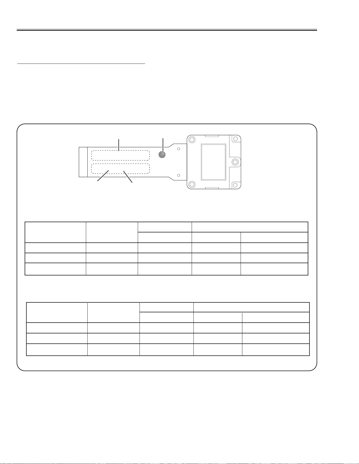
COMBINATION-(1)
COMBINATION-(2)
Type A * Type B
SEAL PART NO. PART NO. SERVICE PART NO.
R-LCD PANEL RED SEAL P09SG210 P09SG210B 645 041 3964
G-LCD PANEL NO SEAL P09SG220 P09SG220B 645 041 3957
B-LCD PANEL BLUE SEAL P09SG210 P09SG210B 645 041 3971
● COMBINATION OF LCD PANELS
When replacing the LCD panel, confirm the indication of the LCD panel, then replace the correct LCD panel.
Select either combination (1) or (2) when in combine the R, G and B LCD panel.
There is no combination to be used except them.
As the only Type B LCD panels are supplied for the service spare parts, the service par ts for the Type A LCD pan-
els are not available. Please order the Type B LCD panels for replacement.
For example, if you intend to replace the R-LCD panel which is indicated part no.“P09SG220” with red seal, the
combination of LCD panels for this projector is employed COMBINATION-(1). So the service parts for R-LCD panel
should be PART NO.“P09SG220B” / SERVICE PART NO. “645 041 3995”.
Type A * Type B
SEAL PART NO. PART NO. SERVICE PART NO.
R-LCD PANEL RED SEAL P09SG220 P09SG220B 645 041 3995
G-LCD PANEL NO SEAL P09SG210 P09SG210B 645 041 3988
B-LCD PANEL BLUE SEAL P09SG220 P09SG220B 645 041 4008
SEAL
PART NO.
LOT NO.
P09SG210
1-A-1234A9
TYPE NO.
A :Type A
B :Type B
* These are not supplied as a service parts.

-21-
● REPLACED LCD PANEL ADJUSTMENTS
After replacing LCD panels, [Video Adjustment] should be carried out for obtaining better performance.This only
required when replacing the LCD panel from “Type A” to “Type B”.
● In case of Green LCD panel replaced
1. Enter to the ser vice mode and select COMPUTER
mode.
2. Select item no. “13” and decrease the data value 6
steps from the current value.
3. Select item no. “14” and decrease the data value 6
steps from the current value.
4. Select VIDEO mode and perform the above same
adjustment.
● In case of Red LCD panel replaced
1. Enter to the ser vice mode and select COMPUTER
mode.
2. Select item no. “13” and increase the data value 6
steps from the current value.
3. Select VIDEO mode and perform the above same
adjustment.
● In case of Blue LCD panel replaced
1. Enter to the ser vice mode and select COMPUTER
mode.
2. Select item no. “14” and increase the data value 6
steps from the current value.
3. Select VIDEO mode and perform the above same
adjustment.
● In case of Red and Blue LCD panels replaced
1. Enter to the ser vice mode and select COMPUTER
mode.
2. Select item no. “13” and increase the data value 6
steps from the current value.
3. Select item no. “14” and increase the data value 6
steps from the current value.
4. Select VIDEO mode and perform the above same
adjustment.
● In case of Red and Green LCD panels replaced
1. Enter to the ser vice mode and select COMPUTER
mode.
2. Select item no. “14” and decrease the data value 6
steps from the current value.
3. Select VIDEO mode and perform the above same
adjustment.
After performing the adjustment, please confirm the
white balance in COMPUTER, VIDEO and MCI mode.
If required the readjustment, please follow the [WHITE
BALANCE ADJUSTMENT] on page 31.
● In case of Blue and Green LCD panels replaced
1. Enter to the ser vice mode and select COMPUTER
mode.
2. Select item no. “13” and decrease the data value 6
steps from the current value.
3. Select VIDEO mode and perform the above same
adjustment.
Please change the data value of service data for referring to the following adjustment.This should be performed
when replacing the LCD panel.
(To enter the ser vice mode, refer to “Service Adjustment Menu Operation” on page 26.)
VIDEO ADJUSTMENT
-22-
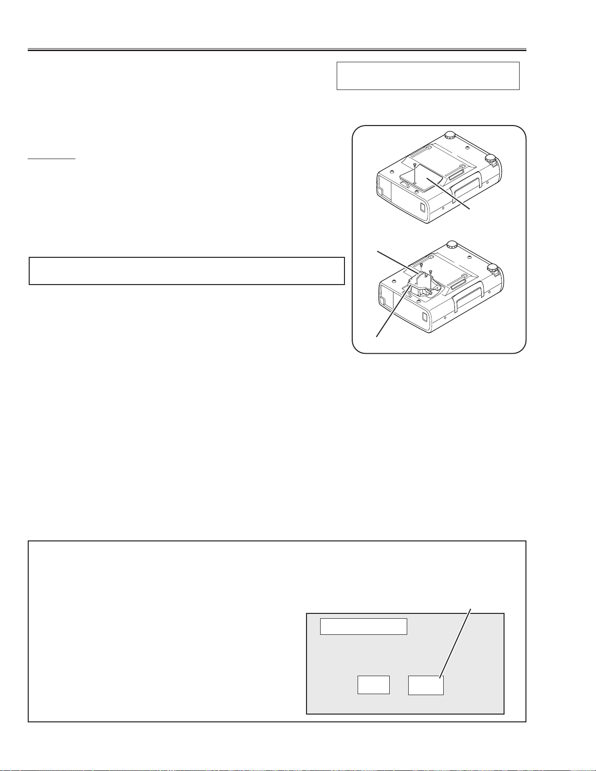
■ Lamp Replacement
WARNING:
- For continued safety, replace with a lamp assembly of the same type.
- Allow the projector to cool for at least 45 minutes before you open the lamp cover. The inside of the projector can
become very hot.
- Do not drop the lamp module or touch the glass bulb! The glass can shat-
ter and cause injury.
Procedure
1.Turn off the projector and disconnect the AC cord,.Allow the projector to
cool for at lease 45 minutes.
2. Remove a screw with a screwdriver and remove the lamp cover.
3. Remove 2 screws and pull out the lamp assembly by grasping the han-
dle.
4. Replace the lamp assembly securely and tighten 2 screws.
5. Place the lamp cover and tighten a screw.
6. Connect the AC cord to the projector and turn on.
Note:
- Do not reset the LAMP REPLACEMENT MONITOR TIMER, except after
the lamp is replaced.
- The projector can not be turned-on with the lamp cover removed,
because when the lamp cover is removed, the interlock switch is also
released to switch off the mains power for safety.
7. Reset the lamp replacement monitor timer,see below explanation.
Service Parts No.: 610 280 6939
Description: Lamp Assy (POA-LMP21J)
How to reset the lamp replacement moni-
tor timer
1.Turn the projector on. Press the MENU button on the
projector and the On-Screen menu will appear.Select
setting menu and select “Lamp age” on the setting
menu of menu bar.
2.“Lamp replace monitor Reset?” is displa y ed for confir-
mation.Select “Yes” to reset the lamp replace timer.
Please refer to the owners manual for further informa-
tion.
Recommendation
Should the air filter become clogged with dust particles,
it will reduce the cooling fan’s effectiveness and may
result in internal heat build up and short lamp life. We
recommend cleaning the air filter after the projection
lamp is replaced.
Refer to “Air Filter Cleaning”.
How to check the lamp replace monitor
time
The LAMP REPLACEMENT indicator will illuminate
when the accumulated illumination time of the lamp
reaches 1000 hours.This is to indicate that lamp
replacement is necessary.
You can check the accumulated illumination time of
the lamp by following procedure.
1. Press and hold the pointer ▲ on the projector for
more than 20 seconds.
2.The projector enters to the service mode and the
accumulated time is displayed in the Data column
with hours unit. For example, when “123” is dis-
played, the accumulated illumination time of the
lamp is 123 hours.This will disappear in 5 seconds.
Lamp cover
Lamp Assembly
Handle
Video
Item Data
Service Mode
36
123
Accumulated illumi-
nation time of lamp
-23-
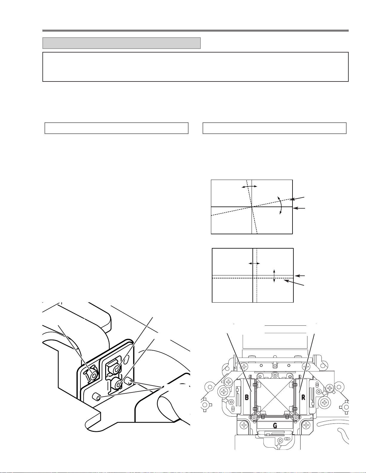
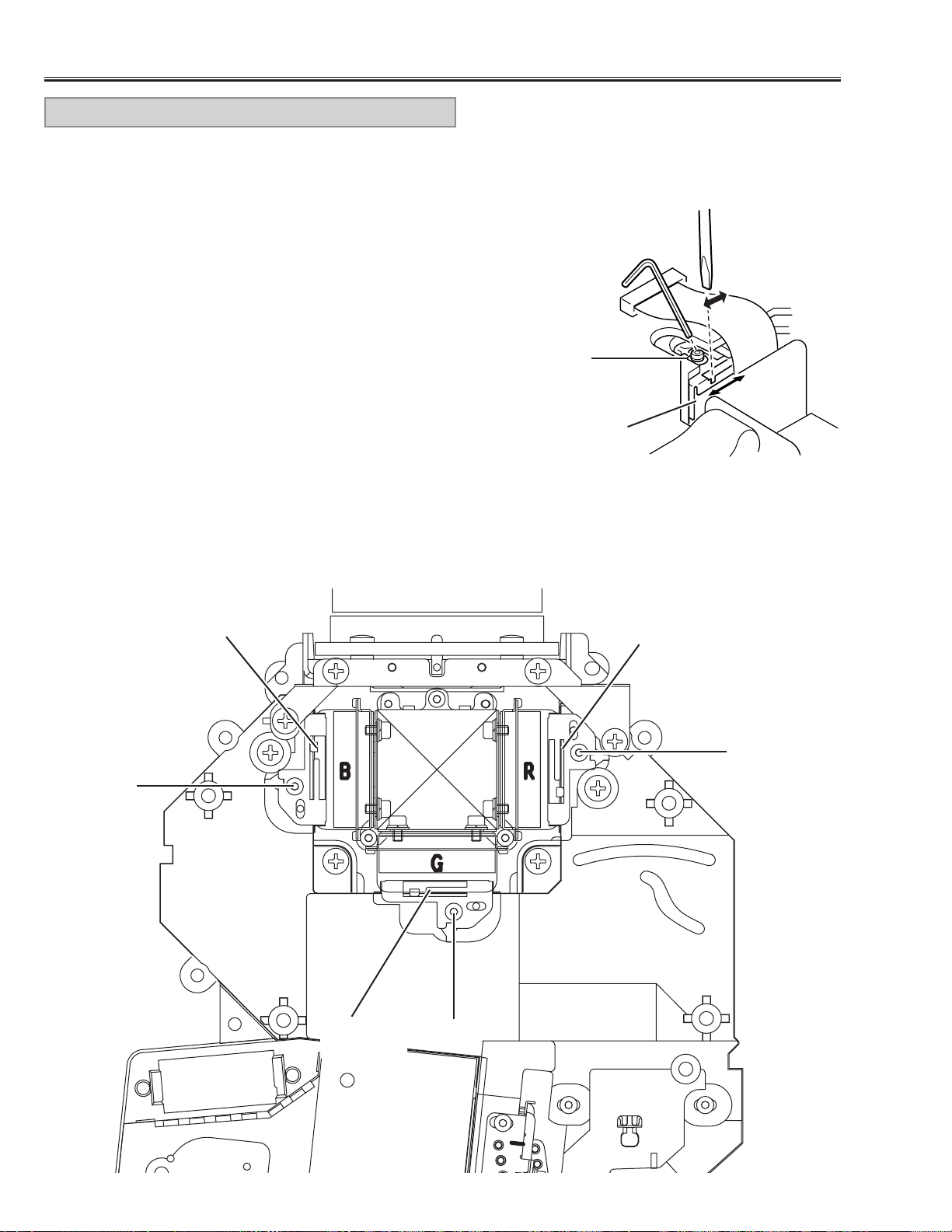
[Before adjustment]
- Make sure each Red, Green and Blue LCD panel unit has been correctly installed.
- Input a grid pattern signal.
- Adjustment requires a 2.0mm hex wrench. Remove cabinet top following to the “Mechanical Disassemblies”.
1.Insert paper etc. in Red or Blue panel to block the red
or blue light so that either green and red or green and
blue lights are projected. (For example, when adjust
Red panel convergence, project green and red lights,
and when adjust Blue panel, project green and blue
lights.)
2. Loosen 2 screws “D” (Fig.1) using the 2.0mm hex
wrench.
3.Turning the screw “A”, align so that the Red (or Blue)
horizontal lines are parallel to the Green horizontal
lines (Fig.1-a).
4. Turning screw “B”, align the Red (or Blue) vertical
lines onto the Green vertical lines (Fig.1-b).
5. Turning screw “C”, align the Red (or Blue) horizontal
lines onto the Green horizontal lines (Fig.1-b).
6. By repeating steps 3 to 5, align the Red (or Blue) grid
lines onto the green lines.
7.Tighten the 2 screws “D”to fix the Red (or Blue) panel
unit.
RED/BLUE PANEL CONVERGENCE
1. Adjustment screw “A” tur ns the image (Fig.1-a).
2. Adjustment screw “B” moves the image right and left
(Fig.1-b).
3. Adjustment screw ”C” moves the image up and down
(Fig.1-b).
[Image Movement and Screw Turning]
C: up/down
B: right/left
A: angle
D: Fixing
Fig.1-a
Red or Blue
Green
A
Fig.1-b
Red or Blue
Green
C
B
Red LCD panel
Blue LCD panel
For convergence adjustment, use Green as the reference standard. Align Red and Blue with Green by adjusting
the position and angle of the Red and Blue LCD panels. Screws “A”, “B”, “C” (Fig.1) are for convergence adjust-
ment.
CONVERGENCE ADJUSTMENT
Fig.1
Fig.2
■ Optical Adjustments
-24-
Optical Adjustments
[Before Adjustment]
- Adjustment requires a 2.0mm hex wrench and a slot screwdriver.
- Remove cabinet cover following to step1 of “Mechanical Disassemblies”.
- Input a 100% of black raster signal.
[R/G/B-CONTRAST ADJUSTMENT]
1. Insert paper etc. in front of the LCD panels to block unnecessary
lights.
When adjusting the R-Contrast, project red light only.
When adjusting the G-Contrast, project green light only.
When adjusting the B-Contrast, project blue light only.
2. Loosen a screw “A” (Fig.3/4) on the polarized glass mounting base
which you intend to adjust.
3. Turn the polarized glass mounting base by using a slot driver as
shown in Fig.3 to obtain the darkest brightness on the screen.
4.Tighten the screw “A”to fix the polarized glass mounting base.
Repeat steps 1 to 4 for remaining polarized glasses.
B-Polarized
glass
R-Polarized
glass
G-Polarized
glass
A
A
A
A
Fig.4
Fig.3
Polarized
glass
CONTRAST ADJUSTMENT
-25-
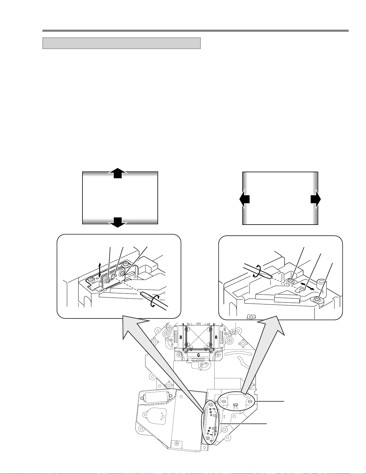
Optical Adjustments
[Adjustment]
1.Turn on lamp by a state of without FPC cable of LCD
panels.
2. Inser t a light block sheet in front of the Blue panel to
block the blue light so that red and g reen light are pro-
jected.
3. Adjust the adjustment base of integrator lens-IN and
integrator lens-OUT to make color uniformity in yel-
low.
1) If the un-uniform color appears on the top or bot-
tom of the screen as shown in Fig.5-a, loosen 2
screws “A” (Fig.5-b) with hex driver and insert a
slot screwdriver into slot “B” and turn it to make
color uniformity in yellow.
2) If the un-uniform color appears on the left or right
of the screen as shown in Fig.5-c, loosen 2 screws
“C” (Fig.5-d) with the hex driver and insert a slot
screwdriver into slot “D” and tur n it to make color
uniformity in yellow.
6. Tighten the 2 screws “A” or “C” to fix the integrator
lens-IN and OUT unit.
Slot B
Fig.5-b
Fig.5-a
Fig.5-c
INTEGRATOR LENS ADJUSTMENT
Yellow
A
A
Slot D
Fig.5-d
C
C
[Before Adjustment]
- Adjustment requires a 2.0mm hex driver and a slot screwdriver.
- Remove the cabinet top following to “Cabinet Disassemblies”.
- Disconnect AV sub board and connectors FPC cable of LCD panels on the main unit.
Yellow
Fig.5
Integrator Lens-IN
Integrator Lens-OUT
-26-
■ Electrical Adjustments
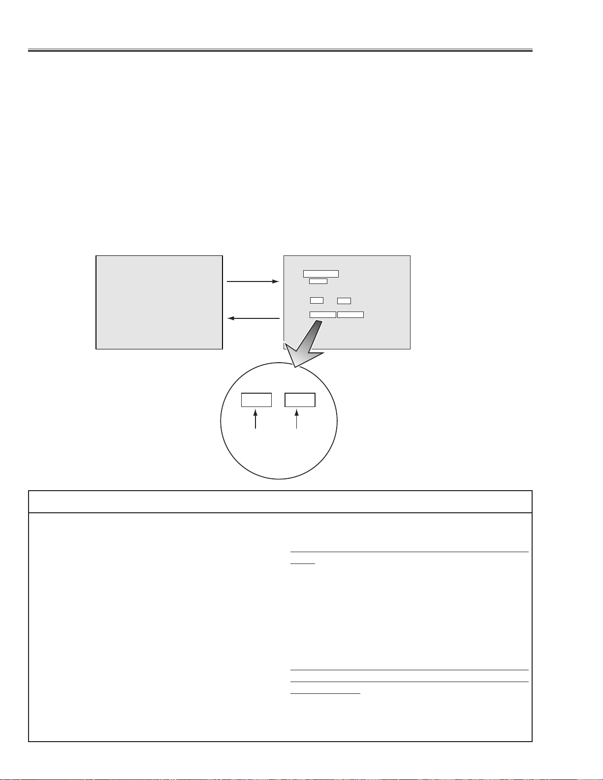
To enter the ser vice mode
To enter the “Service Mode”, press and hold the MENU and NORMAL button on the projector for more than 3 sec-
onds.The ser vice mode display appears on the screen as follows.
To adjust ser vice data
Select the adjustment item no.by pressing the pointer ▲ or ▼ button, and change the data value by pressing the
VOLUME + or VOLUME - button. Refer to the “Ser vice Adjustment Data Table” for further descroption of adjust-
ment item no.and data value.
To exit the service mode
To exit the service mode, press any of the POWER ON-OFF, MENU, MODE, FOCUS or ZOOM buttons on the pro-
jector or remote control unit.
● Service Adjustment Menu Operation
Service Mode
10
15
Video
Version : 1.0
Item Data
10 15
Normal mode Service mode
Adjustment
Item No.
Adjustment
Data Value
Item
Data
IC302 on the main board-A stores the data for the ser-
vice adjustments, and should not be replaced except
for the case of defective device.
If replaced, it should be performed the re-adjustments
following to the “Electrical Adjustments”.
The lamp replacement monitor timer is stored in the
IC302, and it can be confirmed at the item no. 36 of
service mode.
Please note that the lamp replacement monitor timer is
reset when the memory IC (IC302) is replaced.
(Lamp replacement monitor time can not be set to the
previous value.)
● Caution to memory IC replacement
When IC302 is replaced with new one, the CPU writes
down the default data of the service adjustments to the
replaced IC, refer to the service adjustment table. As
these data are not the same data as factory shipped
data, it should be required to perform the re-adjust-
ments following to the “Electrical Adjustments”.
Please note that the lamp replacement monitor timer is
reset.
● Caution of Main Board replacement (in the case
IC302 is not defective)
When the main board-A is replaced, IC302 should be
replaced with the one on previous main board. After
replacement, it should be required to perform the re-
adjustments following to the “Electrical Adjustments”.
In this case, the lamp replacement monitor timer and
the white uniformity compensation data can be kept the
value as before.
● Memory IC Replacement
-27-
After replacing the Power Board, PF.C. Board, readjust
the Output voltage adjustment as follows.
1. Connect a digital voltmeter to pins 1 (+) and 3 (-) of
K6C.
2. Adjust the voltage by using VR01 as following.
AC Input Reading
230V 370V ±2V
120V 320V ±2V
Caution:
Be sure to connect the lamp when taking this adjust-
ment.
OUTPUT VOLTAGE ADJUSTMENT
● Circuit Adjustments
CAUTION:The each circuit has been made by the fine adjustment at factory. Do not attempt to adjust the follow-
ing adjustments except requiring the readjustments in servicing otherwise it may cause loss of perfor-
mance and product safety.
[Adjustment Condition]
● Input signal
Video signal ..................1.0Vp-p/75Ω terminated, 16 steps gray scale or color bar pattern
Computer signal............0.7Vp-p/75Ω terminated, 16 steps gray scale pattern
MCI signal * ..................16 steps gray scale pattern from PC Card
● Picture control mode ---------- “NORMAL” mode unless otherwise noted.
Note:
* Please refer to “Service Adjustment Menu Operation” for entering to the service mode and adjusting the service
data.
* It is not available the MCI mode for model which does not provide the PC Card slot.
Electrical Adjustments
Presetting
1. Receive the 16-step grey scale video signal.
2. Set to VIDEO mode.
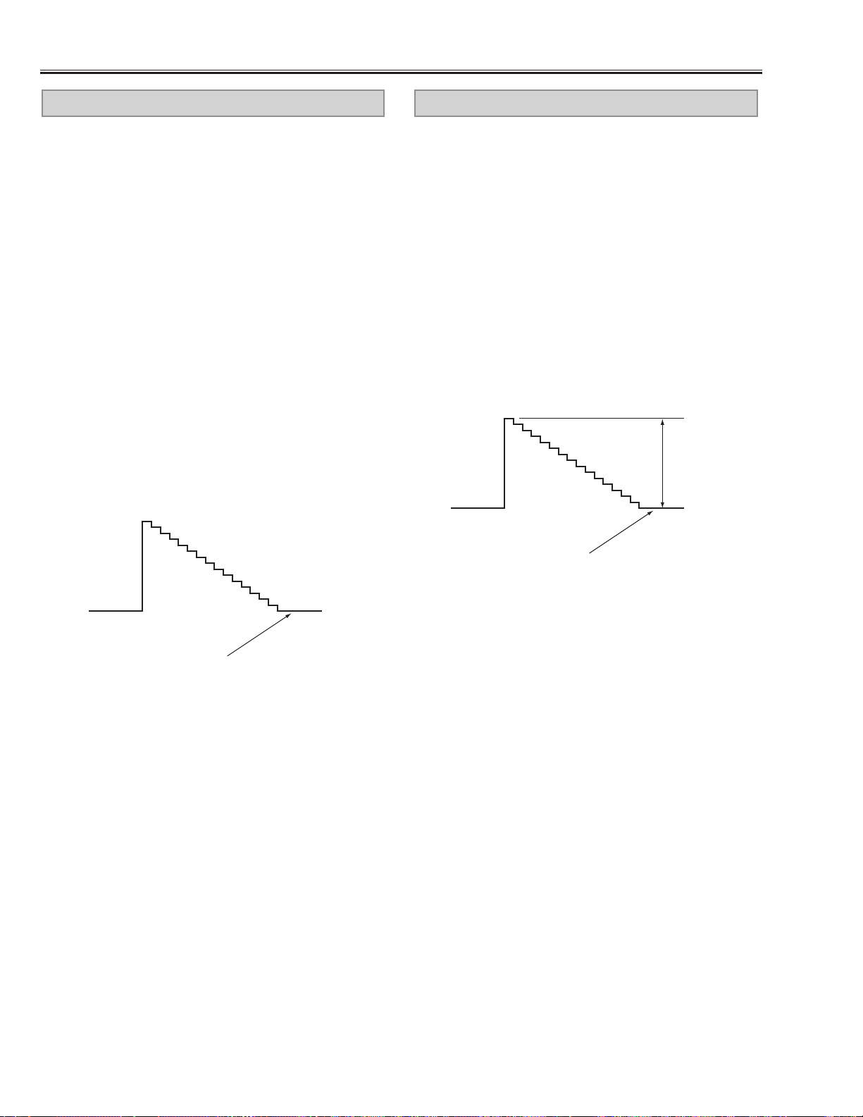
[R-PEDESTAL ADJUSTMENT]
3. Connect an oscilloscope to test point “TP221R” (+)
and chassis ground (-).
4. Enter to the service mode, select item no. “27” and
change data value to adjust the pedestal level and
black level to be same level.
[G-PEDESTAL ADJUSTMENT]
5. Connect an oscilloscope to test point “TP221G” (+)
and chassis ground (-).
6. Select item no.“28” and change data value to adjust
the pedestal level and black level to be same level.
[B-PEDESTAL ADJUSTMENT]
7. Connect an oscilloscope to test point “TP221B” (+)
and chassis ground (-).
8. Select item no.“29” and change data value to adjust
the pedestal level and black level to be same level.
Pedestal level = Black level
PEDESTAL ADJUSTMENT
-28-
Electrical Adjustments
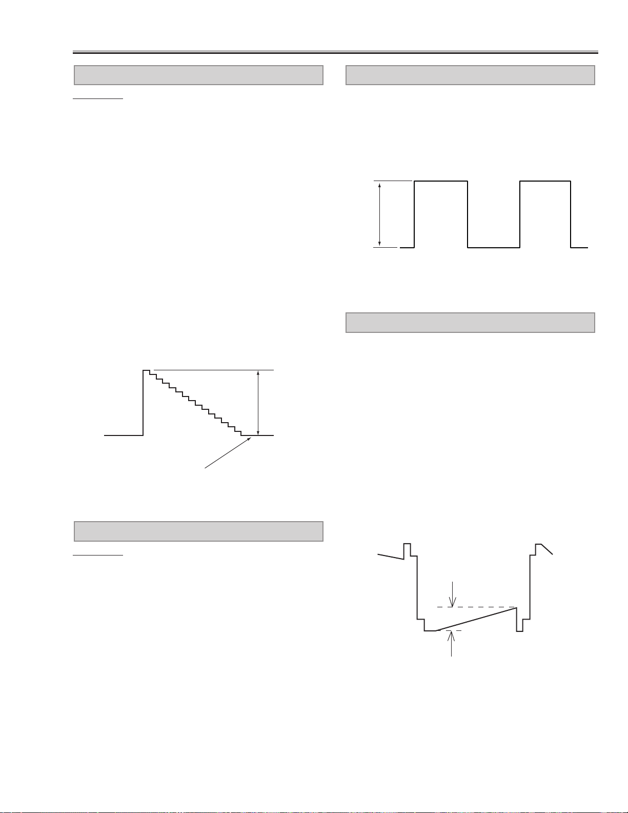
[CG-VIDEO GAIN ADJUSTMENT]
1. Receive the 16-step grey scale computer signal.
2. Set to COMPUTER mode.
3. Connect an oscilloscope to test point “TP2221G” (+)
and chassis ground (-).
4. Enter to the service mode, select item no. “48” and
change data value to adjust “a”to be 1.15 ±0.01Vp-p.
[MCI-VIDEO GAIN ADJUSTMENT] *
5. Receive the 16-step grey scale MCI signal.
6. Set to MCI mode.
7. Connect an oscilloscope to test point “TP2221G” (+)
and chassis ground (-).
8. Enter to the service mode, select item no. “48” and
change data value to adjust “a”to be 1.15 ±0.01Vp-p.
VIDEO GAIN ADJUSTMENT-[CG/MCI]
1. Receive the 16-step gray scale video signal.
2. Set to COMPUTER mode.
[R-OFFSET ADJUSTMENT]
3. Connect an oscilloscope to test point “TP2211R” (+)
and chassis ground (-).
4. Enter to the service mode, select item no. “45” and
change data value to adjust the pedestal level and
black level to be same level.
[G-OFFSET ADJUSTMENT]
5. Connect an oscilloscope to test point “TP2221G” (+)
and chassis ground (-).
6. Select item no.“46” and change data value to adjust
the pedestal level and black level to be same level.
[B-OFFSET ADJUSTMENT]
7. Connect an oscilloscope to test point “TP2231B” (+)
and chassis ground (-).
8. Select item no.“47” and change data value to adjust
the pedestal level and black level to be same level.
Pedestal level = Black level
OFFSET ADJUSTMENT-[CG]
Pedestal level = Black level
(a)
-29-
Electrical Adjustments
Presetting
1. Receive the 16-step grey scale video signal.
2. Set to VIDEO mode.
[R-VIDEO GAIN ADJUSTMENT]
3. Connect an oscilloscope to test point “TP2211R” (+)
and chassis ground (-).
4. Enter to the service mode, select item no. “49” and
change data value to adjust “a”to be 1.12 ±0.02Vp-p.
[G-VIDEO GAIN ADJUSTMENT]
5. Connect an oscilloscope to test point “TP2221G” (+)
and chassis ground (-).
6. Enter to the service mode, select item no. “50” and
change data value to adjust “a”to be 1.12 ±0.02Vp-p.
[B-VIDEO GAIN ADJUSTMENT]
7. Connect an oscilloscope to test point “TP2231B” (+)
and chassis ground (-).
8. Enter to the service mode, select item no. “51” and
change data value to adjust “a”to be 1.12 ±0.02Vp-p.
Pedestal level = Black level
(a)
VIDEO-GAIN ADJUSTMENT-[AV]
Presetting
1. Receive the 16-step grey scale computer signal.
2. Set to COMPUTER mode.
[R-VIDEO CENTER ADJUSTMENT]
3. Connect a digital voltmeter to test point “TP511” (+)
and chassis ground (-).
4. Adjust voltage to be 7.30 ±0.05V by using VR501.
[G-VIDEO CENTER ADJUSTMENT]
5. Connect a digital voltmeter to test point “TP512” (+)
and chassis ground (-).
6. Adjust voltage to be 7.30 ±0.05V by using VR531.
[B-VIDEO CENTER ADJUSTMENT]
7. Connect a digital voltmeter to test point “TP513” (+)
and chassis ground (-).
8. Adjust voltage to be 7.30 ±0.05V by using VR561.
VIDEO CENTER ADJUSTMENT
1. Receive the 16-step grey scale computer signal.
2. Set to COMPUTER mode.
3. Connect an oscilloscope to test point “TP3571” (+)
and chassis ground (-).
4. Adjust “a” to be 5.0 ±0.1V by using VR3571.
(a)
NRS ADJUSTMENT
[GAMMA OFF ADJUSTMENT-CG]
1. Receive the 16-step gray scale computer signal.
2. Set to COMPUTER mode.
3. Connect an oscilloscope to test point “TP512” (+) and
chassis ground (-).
4. Enter to the service mode, select item no. “0” and
change data value to adjust “a”to be 1.70 ±0.01Vp-p.
[GAMMA OFF ADJUSTMENT-AV]
5. Receive the 16-step gray scale video signal.
6. Set to VIDEO mode.
7. Connect an oscilloscope to test point “TP512” (+) and
chassis ground (-).
8. Enter to the service mode, select item no. “0” and
change data value to adjust “a”to be 1.70 ±0.01Vp-p.
GAMMA OFF VIDEO ADJUSTMENT
(a)
-30-
1. Receive the 16-step gray scale computer signal.
2. Set to COMPUTER mode.
3. Connect an oscilloscope to test point “TP512” (+) and
chassis ground (-).
4. Enter to the service mode, select item no. “3” and
change data value to adjust “a”to be maximum.
(a)
S/H CLOCK ADJUSTMENT
Electrical Adjustments
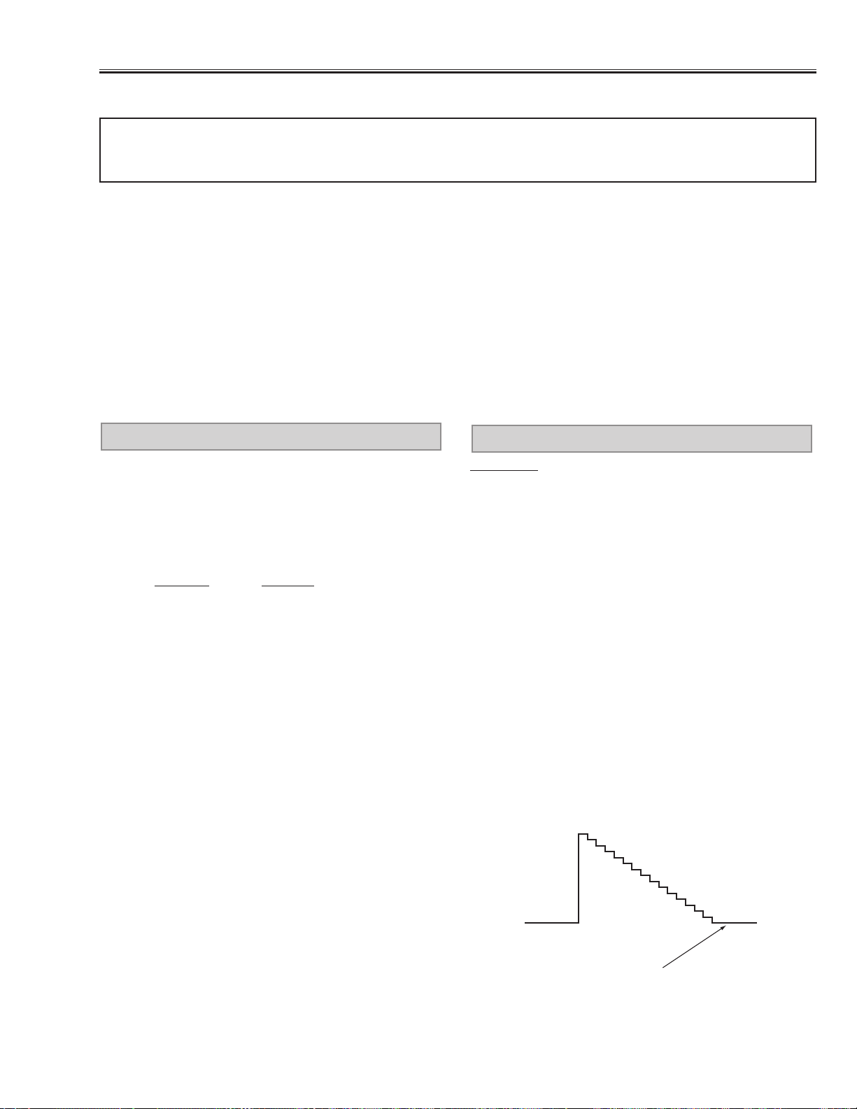
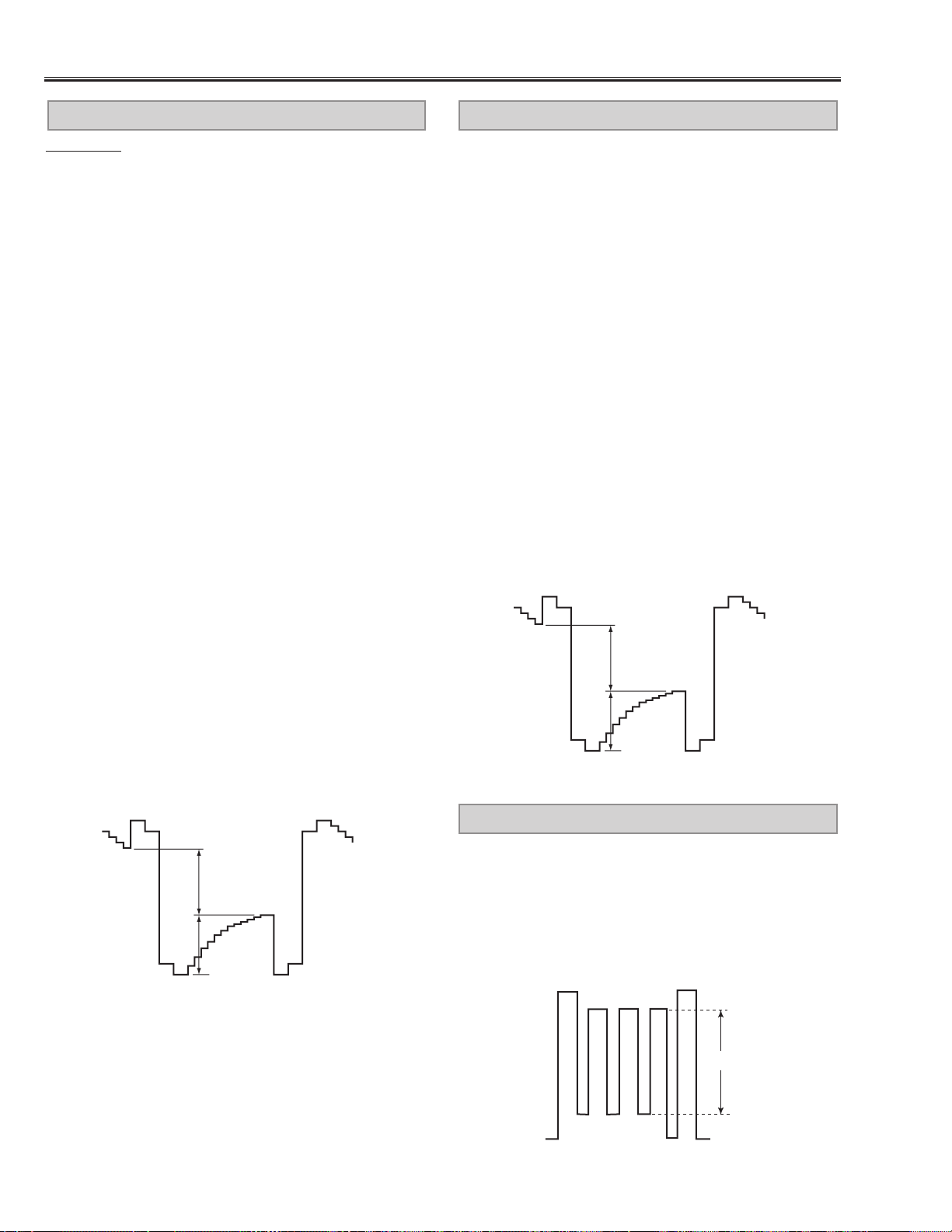
Presetting
1. Input the 16-step gray scale video signal, MCI signal
and computer signal.
[CG/MCI/AV-VIDEO ADJUSTMENT] *
2. Connect an oscilloscope to test point “TP512” (+) and
chassis ground (-).
3. Enter to the service mode, select item no. “15” and
change data value to adjust “b”to be 1.6Vp-p at each
VIDEO, MCI and COMPUTER mode.
4. Select COMPUTER and MCI mode, select item no.
“12” and change data value to adjust “a” to be 4.05
±0.01Vp-p.
5. Select VIDEO mode, select item no.“12” and change
data value to adjust “a”to be 4.05 ±0.01Vp-p.
[R-VIDEO ADJUSTMENT]
6. Connect an oscilloscope to test point “TP511” (+) and
chassis ground (-).
7. Enter to the service mode and select COMPUTER
mode.
8. Select item no. “13” and change data value to adjust
“a” to be 4.05 ±0.01Vp-p.
9. Select VIDEO mode and item no. “13” and change
data value to adjust “a”to be 4.05 ±0.01Vp-p.
[B-VIDEO ADJUSTMENT]
10. Connect an oscilloscope to test point “TP513” (+)
and chassis ground (-).
11.Enter to the service mode and select COMPUTER
mode.
12. Select item no.“14” and change data value to adjust
“a” to be 4.05 ±0.01Vp-p.
13. Select VIDEO mode and item no. “14” and change
data value to adjust “a”to be 4.05 ±0.01Vp-p.
(a)
(b)
black level
white level
white level
CG/MCI/A V VIDEO ADJUSTMENT -1
[CG-VIDEO ADJUSTMENT-2]
1. Receive the 16-step grey scale computer signal.
2. Set to COMPUTER mode.
3. Connect an oscilloscope to test point “TP512” (+) and
chassis ground (-).
4. Enter to the service mode, select item no. “15” and
change data value to adjust “b”to be 2.20 ±0.01Vp-p.
[MCI-VIDEO ADJUSTMENT-2] *
5. Receive the 16-step grey scale MCI signal.
6. Set to MCI mode.
7. Connect an oscilloscope to test point “TP512” (+) and
chassis ground (-).
8. Enter to the service mode, select item no. “15” and
change data value to adjust “b”to be 2.20 ±0.01Vp-p.
[AV-VIDEO ADJUSTMENT-2]
9. Receive the 16-step grey scale video signal.
10. Set to VIDEO mode.
11. Connect an oscilloscope to test point “TP512” (+)
and chassis ground (-).
12. Enter to the ser vice mode, select item no. “15” and
change data value to adjust “b”to be 2.30 ±0.01Vp-p.
(a)
(b)
black level
white level
white level
CG/MCI/A V VIDEO ADJUSTMENT -2
 Loading...