

Sanyo PLC-EF10BA, PLC-EF10BAL Instruction Manual
Multimedia Projector
MODEL PLC-EF10BA
MODEL PLC-EF10BAL (Without Lens)
OWNER'S INSTRUCTION MANUAL
TO THE OWNER
As the owner of a new Multi-media Projector, you are probably eager to try out your new projector. Before you do, we suggest that you spend a little time reading this manual to familiarize yourself with the operating procedures, so that you will receive maximum satisfaction from the many features included in your new projector.
This owner's manual will acquaint you with your projector's features. Reading it will help us too. Through the years, we have found that many service requests were not caused by problems with our projectors. They were caused by problems that could have been prevented, if the owner had followed the instructions in the manual.
You can often correct operating problems yourself. If your projector fails to work properly, see "TROUBLESHOOTING" section on pages 55 ~ 56 and try the solutions marked for each problem.
SAFETY PRECAUTIONS
WARNING:
TO REDUCE THE RISK OF FIRE OR ELECTRIC SHOCK, DO NOT EXPOSE THIS APPLIANCE TO RAIN OR MOISTURE.
Intense light source. Do not stare directly into the projection lens as possible eye damage could result.
Be especially careful that children do not stare directly into the beam.
The Remote Control Unit, supplied to this projector, emits the laser beam as the Laser Pointer function from the Laser Light Window while pressing the LASER button. Do not look into the Laser Light Window or shine the laser beam on yourself or other people. Eye damage may result.
If the Projector will not be used for an extended time, unplug the new Projector from the power outlet.
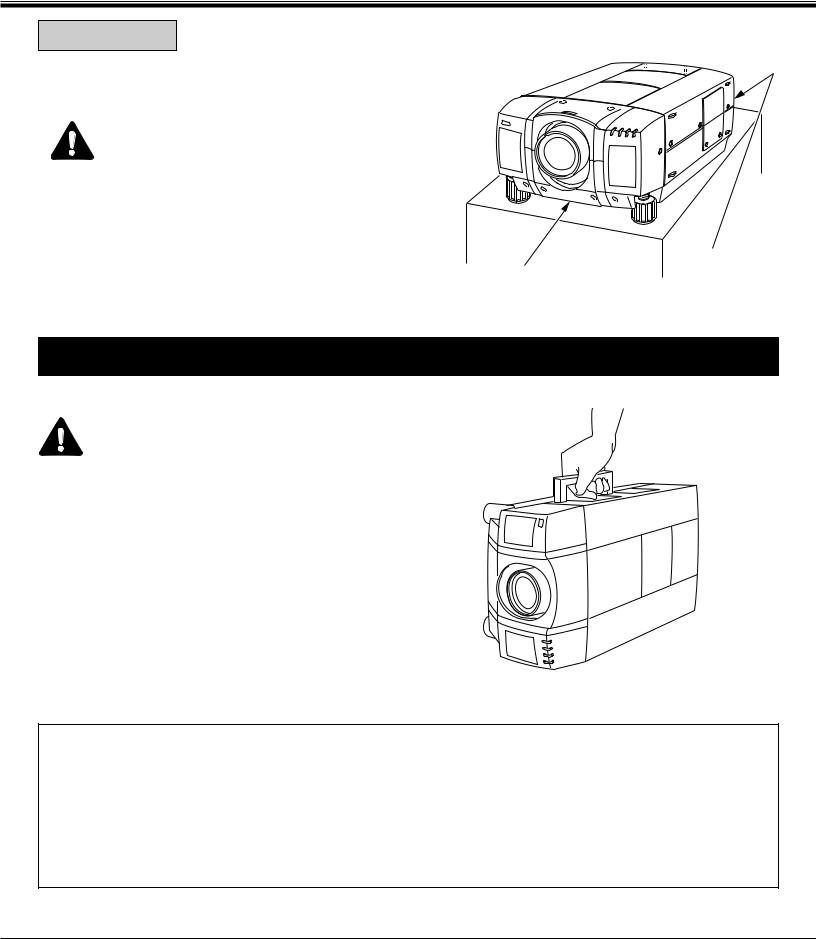
This Projector should be set in the way indicated. Never hang the projector, or fall down on its side. It may result in fire hazard.
READ AND KEEP THIS OWNER'S MANUAL FOR LATER USE.
IMPORTANT:
For your protection in the event of theft or loss of this LCD projector, please record the Model Number and Serial Number located on the rear of unit and retain this information. Refer to these numbers whenever you call upon your authorized dealer regarding this product.
Do not discard shipping carton and packing materials. These items may be needed for storage or future servicing.
Model No :
Serial No :
IMPORTANT: (UK MODEL ONLY)
This cord is already fitted with a moulded plug incorporating a fuse, the value of which is indicated on the pin face of the plug. Should the fuse need to be replaced, an ASTA approved BS 1362 fuse must be used of the same rating, marked thus ASA . If the fuse cover is detachable, never use the plug with the cover omitted. If a replacement fuse cover is required, ensure it is of the same colour as that visible on the pin face of the plug (i.e. red or orange). Fuse covers are available from the Parts Department indicated in your User Instructions.
If the plug supplied is not suitable for your socket outlet, it should be cut off and destroyed. The end of the flexible cord should be suitably prepared and the correct plug fitted. (See Over)
WARNING: A PLUG WITH BARED FLEXIBLE CORDS IS HAZARDOUS IF ENGAGED IN A LIVE SOCKET OUTLET.
The Wires in this mains lead are coloured in accordance with the following code:
Green-and-yellow |
Earth |
Blue |
Neutral |
Brown |
Live |
As the colours of the wires in the mains lead of this apparatus may not correspond with the coloured markings identifying the terminals in your plug proceed as follows:
The wire which is coloured green-and yellow must be connected to the terminal in the plug which is marked by the letter E or by the safety earth symbol  or coloured green or green-and-yellow.
The wire which is coloured blue must be connected to the terminal which is marked with the letter N or coloured black. The wire which is coloured brown must be connected to the terminal which is marked with the letter L or coloured red.
WARNING: THIS APPARATUS MUST BE EARTHED.
2
IMPORTANT SAFETY INSTRUCTIONS
All the safety and operating instructions should be read before the product is operated.
Read all of the instructions given here and retain them for later use. Unplug this projector from AC power supply before cleaning. Do not use liquid or aerosol cleaners. Use a damp cloth for cleaning.
Do not use attachments not recommended by the manufacturer as they may cause hazards.
Do not place this projector on an unstable cart, stand, or table. The projector may fall, causing serious injury to a child or adult, and serious damage to the projector. Use only with a cart or stand recommended by the manufacturer, or sold with the projector. Wall or shelf mounting should follow the manufacturer's instructions, and should use a mounting kit approved by the manufacturer.
Do not expose this unit to rain or use near water... for
example, in a wet basement, near a swimming pool, etc...
Slots and openings in the back and bottom of the cabinet are provided for ventilation, to insure reliable operation of the equipment and to protect it from overheating.
The openings should never be covered with cloth or other material, and the bottom opening should not be blocked by placing the projector on a bed, sofa, rug, or other similar surface. This projector should never be placed near or over a radiator or heat register.
This projector should not be placed in a built-in installation such as a bookcase unless proper ventilation is provided.
This projector should be operated only from the type of power source indicated on the marking label. If you are not sure of the type of power supplied, consult your authorized dealer or local power company.
Do not overload wall outlets and extension cords as this can result in fire or electric shock. Do not allow anything to rest on the power cord. Do not locate this projector where the cord will be abused by persons walking on it.
Never push objects of any kind into this projector through cabinet slots as they may touch dangerous voltage points or short out parts that could result in a fire or electric shock. Never spill liquid of any kind on the projector.
Do not attempt to service this projector yourself as opening or removing covers may expose you to dangerous voltage or other hazards. Refer all servicing to qualified service personnel.
Unplug this projector from wall outlet and refer servicing to qualified service personnel under the following conditions:
a.When the power cord or plug is damaged or frayed.
b.If liquid has been spilled into the projector.
c.If the projector has been exposed to rain or water.
d.If the projector does not operate normally by following the operating instructions. Adjust only those controls that are covered by the operating instructions as improper adjustment of other controls may result in damage and will often require extensive work by a qualified technician to restore the projector to normal operation.
e.If the projector has been dropped or the cabinet has been damaged.
f.When the projector exhibits a distinct change in performance-this indicates a need for service.
When replacement parts are required, be sure the service technician has used replacement parts specified by the manufacturer that have the same characteristics as the original part. Unauthorized substitutions may result in fire, electric shock, or injury to persons.
Upon completion of any service or repairs to this projector, ask the service technician to perform routine safety checks to determine that the projector is in safe operating condition.
Follow all warnings and instructions marked on the projectors.
For added protection to the projector during a lightning storm, or when it is left unattended and unused for long periods of time, unplug it from the wall outlet. This will prevent damage due to lightning and powerline surges.
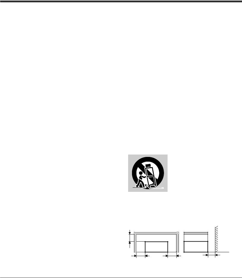
An appliance and cart combination should be moved with care. Quick stops, excessive force, and uneven surfaces may cause the appliance and cart combination to overturn.
If the projector is to be built into a compartment or similarly enclosed, the minimum distances must be maintained.
Do not cover the ventilation slot on the projector.
Heat build-up can reduce the service life of your projector, and can also be dangerous.
50cm |
|
WALL |
|
|
|
PROJECTOR |
PROJECTOR |
|
(FRONT) |
(SIDE) |
|
50cm |
50cm |
50cm |
3

TABLE OF CONTENTS
FEATURES AND DESIGN
INTRODUCTION
COMPATIBILITY
IMAGE RESOLUTION
AUTOMATIC MULTISCANNING SYSTEM SCREEN MODE
MULTILANGUAGE
UNPACKING THE PROJECTOR
TRADEMARKS
INSTALLATION
NAME OF EACH PART OF THE PROJECTOR SETTING-UP THE PROJECTOR
MOVING THE PROJECTOR
POWER REQUIREMENTS
CONNECTING THE PROJECTOR
TERMINAL OF THE PROJECTOR
CONNECTING THE COMPUTER
CONNECTING THE VIDEO EQUIPMENT
BEFORE OPERATION
CONTROLS AND INDICATOR
OPERATION OF THE REMOTE CONTROL
WIRELESS REMOTE CONTROL UNIT
WIRELESS REMOTE CONTROL UNIT
CONTROL THE PROJECTOR
DIRECT OPERATION
MENU OPERATION
BASIC OPERATION
TURNING ON/OFF THE PROJECTOR
DIRECT OPERATION
MODE SELECT
SOUND VOLUME ADJUSTMENT
SOUND MUTE FUNCTION
ZOOM ADJUSTMENT
FOCUS ADJUSTMENT
LENS SHIFT ADJUSTMENT
DIGITAL ZOOM FUNCTION
NORMAL PICTURE FUNCTION
FREEZE PICTURE FUNCTION
NO SHOW FUNCTION
|
|
PAGE |
|
5 |
P-TIMER FUNCTION |
34 |
|
5 |
AUTO IMAGE FUNCTION |
34 |
|
CURSOR FUNCTION |
34 |
||
5 |
|||
MENU OPERATION |
35-36 |
||
5 |
|||
MODE SELECT |
35 |
||
5 |
|||
SOUND ADJUSTMENT |
36 |
||
5 |
|||
LANGUAGE ADJUSTMENT |
36 |
||
5 |
|||
|
|
||
5 |
VIDEO MODE |
37-39 |
|
5 |
|||
COLOUR SYSTEM SELECT |
37 |
||
|
|||
6-9 |
VIDEO SOURCE SELECT |
37 |
|
PICTURE IMAGE ADJUSTMENT |
38 |
||
6 |
|||
PICTURE SCREEN ADJUSTMENT |
39 |
||
7 |
|||
|
|
||
8 |
COMPUTER MODE |
40-49 |
|
9 |
|||
COMPUTER SYSTEM SELECT |
40 |
||
|
|||
10-21 |
COMPATIBLE COMPUTER SPECIFICATIONS |
41 |
|
AUTO IMAGE FUNCTION |
42 |
||
10-11 |
|||
PICTURE IMAGE ADJUSTMENT |
43 |
||
12-19 |
|||
PICTURE POSITION ADJUSTMENT |
44 |
||
20-21 |
|||
PC ADJUSTMENT |
45-48 |
||
|
|||
22-31 |
PICTURE SCREEN ADJUSTMENT |
49 |
|
|
|
||
22-23 |
OTHER FUNCTION SETTING |
50-52 |
|
24-28 |
BLUE BACK |
50-51 |
|
24-26 |
|||
DISPLAY |
50-51 |
||
27-28 |
|||
REVERSE T/B |
50-51 |
||
29-31 |
|||
REVERSE L/R |
50-51 |
||
29 |
|||
SPLIT WIPE |
50-51 |
||
30-31 |
|||
POWER MANAGEMENT |
50-51 |
||
|
|||
32-51 |
USB (Mouse or Control) |
50-51 |
|
REMOTE CONTROL (Mode 1 or Mode 2) |
50-51 |
||
32 |
LAMP AGE |
52 |
|
33-34 |
|
|
|
33 |
APPENDIX |
53-57 |
|
33 |
MAINTENANCE |
53-55 |
|
33 |
|||
TEMPERATURE WARNING INDICATOR |
53 |
||
33 |
|||
AIR FILTER CARE AND CLEANING |
53 |
||
33 |
|||
LAMP REPLACEMENT |
54 |
||
33 |
|||
CLEANING THE LENS |
55 |
||
34 |
|||
TROUBLESHOOTING |
55-56 |
||
34 |
|||
TECHNICAL SPECIFICATIONS |
57 |
||
34 |
|||
|
|
||
34 |
|
|
4

FEATURES AND DESIGN
INTRODUCTION
The multimedia projector that combines powerful and sophisticated features with easy-to-use, intuitive controls. Built-in multimedia features include audio, a palette of 16.77 million colours and active matrix liquid crystal display (LCD) technology. The projector is ideal for high-performance business, training and imaging applications that demand exceptional colour quality.
COMPATIBILITY
The projector is compatible with many different types of personal computers and video devices, including:
●IBM-compatible computers, including laptops, up to 1600 x 1200 resolution.
●Apple Macintosh and PowerBook computers up to 1600 x 1200 resolution.
●Various VCRs, video disc players, video cameras, DVD players, satellite TV tuners or other AV equipment using any of the worldwide video standards, including NTSC, NTSC4.43, PAL, PAL-M, PAL-N and SECAM.
IMAGE RESOLUTION
The resolution of the projector's projected image is 1280 x 1024. The projector displays computer images just as they appear on your computer's monitor. Screen resolutions between 1280 x 1024 and 1600 x 1200 are compressed to 1280 x 1024. The projector cannot display screen resolutions above 1600 x 1200. If your computer's screen resolution is higher than 1600 x 1200, reset it to a lower resolution before you connect the projector.
AUTOMATIC MULTISCANNING SYSTEM
This projector can detect display signals from most personal computers currently distributed. It is free from complicated adjustments to project picture images from PC.
SCREEN MODE
Screen display can be selected among; |
|
|
Computer mode |
--- True, Digital zoom (Expand, Compress, Panning) |
|
Video mode |
--- Regular (4:3), Wide (16:9) |
|
|
|
|
MULTILANGUAGE |
|
|
|
|
|
MENU DISPLAY is displayed with; English, German, French, Italian, Spanish and Japanese.
UNPACKING THE PROJECTOR
The projector comes with the parts listed below. Check to find all the parts are included. If any parts are missing, contact an authorized dealer or service station.
● Owner's Manual. |
● AC Power Cord. |
● Wireless Remote Control Unit. |
● Wireless/Wired Remote Control Unit. |
● Remote Control Cable. |
● Batteries for Remote Control Units. |
● Graphic Accelerator Board and its Software. |
● Digital Flat Panel Cable. |
● VGA Cable. |
● Mouse Cable for PS/2 port. |
● Mouse Cable for serial port. |
● Mouse Cable for ADB port. |
● VGA/MAC Adapter. |
● Protective Dust Cover |
● Lens Cover. |
|
TRADEMARKS
●Apple, Macintosh, and PowerBook are trademarks or registered trademarks of Apple Computer, Inc.
●IBM and PS/2 are trademarks or registered trademarks of International Business Machines, Inc.
●Windows is a trademarks or registered trademarks of Microsoft Corporation.
●Other trademarks are the property of their respective owners.
5
INSTALLATION
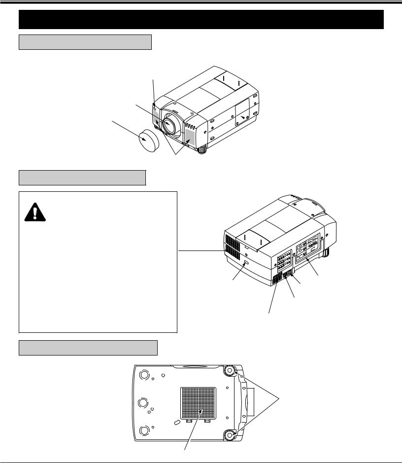
NAME OF EACH PART OF THE PROJECTOR
FRONT OF THE PROJECTOR
INFRARED
REMOTE
RECEIVER
PROJECTION LENS
REMOVABLE
LENS COVER
SPEAKER
REAR OF THE PROJECTOR
EXHAUST VENT
CAUTION HOT AIR!
Air blown from the exhaust vent is hot. Observe the following when handling your projector or choosing a location to install it.
●Keep heat-sensitive objects away from the exhaust port.
●If you set the projector on top of a metallic surface, the surface will become hot because of the hot air exhaust. Be careful when handling.
●Do not touch the cabinet near to the exhaust vent area, and especially screws and metallic parts. These parts will become hot while the projector is used.
 LAMP
LAMP
COVER
|
CARRY |
|
INFRARED |
HANDLE |
|
MAIN ON/OFF |
||
REMOTE |
||
SWITCH |
||
RECEIVER |
||
POWER CORD |
||
|
||
|
CONNECTOR |
|
|
AIR INTAKE |
|
|
VENT |
BOTTOM OF THE PROJECTOR
ADJUSTABLE
FEET
AIR INTAKE VENT
6
INSTALLATION
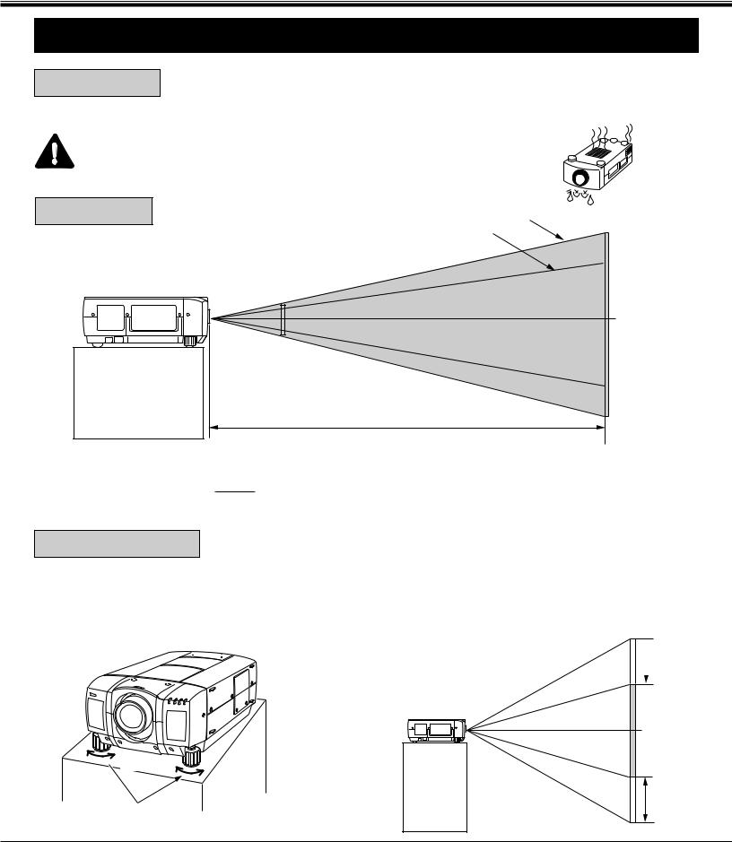
SETTING-UP THE PROJECTOR
● This projector is basically designed to project on a flat projection surface. POSITIONING: ● This projector can be focused from 1.5 m ~ 24.6 m.
● Refer to the figure below as an example when positioning the projector to the screen.
THIS PROJECTOR SHOULD BE SET IN THE WAY INDICATED. NEVER HANG
THE PROJECTOR, OR FALL DOWN ON ITS SIDE. IT MAY RESULT IN FIRE
HAZARD.
ROOM LIGHT
The projector should be placed in a room with limited light. Picture quality will be directly affected by lightning conditions.
40"
|
|
|
|
|
|
|
|
|
|
Maximum Zoom |
600" |
|||
|
|
|
|
|
|
|
|
|
Minimum Zoom |
|||||
|
|
|
|
|
|
|
|
|
|
|||||
|
|
|
|
|
|
|
|
|
400" |
|
||||
100" |
150" |
200" |
300" |
|
|
462" |
||||||||
|
|
|||||||||||||
|
|
|
|
|
||||||||||
|
|
|
|
|
||||||||||
|
|
|
|
|
|
|
|
|||||||
|
|
154" |
|
|
231" |
|
308" |
|
|
|
||||
77" |
|
115" |
|
|
|
|
|
|
|
|||||
|
|
|
|
|
|
|
|
|
||||||
|
|
|
|
|
|
|
|
|
|
|||||
|
|
|
|
|
|
|
|
|
|
|
|
|
|
|
|
|
|
|
|
|
|
|
|
|
|
|
|
|
|
|
|
|
|
|
|
|
|
|
|
|
|
|
|
|
|
|
|
|
|
|
|
|
|
|
|
|
|
|
|
|
|
|
|
|
|
|
|
|
|
|
|
|
|
|
|
|
|
|
|
|
|
|
|
|
|
|
|
|
|
DISTANCE
Screen |
Max. Zoom |
40" |
100" |
150" |
200" |
300" |
400" |
600" |
Size |
Min. Zoom |
|
77" |
115" |
154" |
231" |
308" |
462" |
|
|
|
|
|
|
|
|
|
Distance |
1.5 m |
4.0 m |
6.1 m |
8.2 m |
12.2 m |
16.4 m |
24.6 m |
|
|
|
|
|
|
|
|
|
|
ADJUSTABLE FEET
Picture tilt and projection angle can be adjusted by twisting ADJUSTABLE FEET. Projection angle can be adjusted up to 4 degrees by rotating Adjustable Feet.
 DOWN
DOWN
UP |
DOWN |
UP
ADJUSTABLE FEET
MOVE THE PROJECTED IMAGE POSITION
Adjust the projected image position (maximum 760mm downward or upward on the 100" screen) by using lens shift function. (See page 33.)
 760 mm
100" SCREEN
760 mm
7
INSTALLATION
VENTILATION
This projector is equipped with a cooling fan to protect it from overheating. Pay attention to the following to ensure the ventilation and avoid a possible risk of fire and malfunction.
● Do not cover the vents with papers or other materials.
● Keep the rear grill at least 1m away from any object.
● Make sure that there are no objects under the projector. An object under the projector may prevent the projector from taking the cooling air through the bottom vent.
EXHAUST VENT AIR INTAKE VENT (REAR SIDE) (BOTTOM SIDE)
MOVING THE PROJECTOR
Use the carry handle when moving the projector.
Replace the lens cover and rotate the adjustable feet fully clockwise.
CAUTION IN CARRYING OR TRANSPORTING THE PROJECTOR
●Do not drop or give a shock to the projector, otherwise damage or malfunction may result.
●When carrying the projector, use a Sanyo recommended Carrying Case.
●Do not transport the projector by using a courier or transport service in an unsuitable transport case. This may cause damage to the projector. To transport the projector through a courier or transport service, use a Sanyo recommended Case.
●For a carrying or transportation cases, contact a Sanyo authorized dealer.
8
INSTALLATION
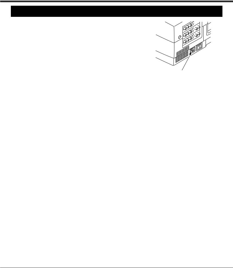
POWER REQUIREMENTS
Your projector uses nominal input voltages of 200-240 VAC. The projector automatically selects the correct input voltage. The projector is designed to work with single-phase power systems having a grounded neutral conductor. To reduce the risk of electrical shock, do not plug into any other type of power system.
Consult your authorized dealer or service station if you are not sure what type of power is supplied to your building.
Connect the AC power supply cord (supplied) to the projector.
The socket-outlet must be near this equipment and must be easily accessible.
9
CONNECTING THE PROJECTOR
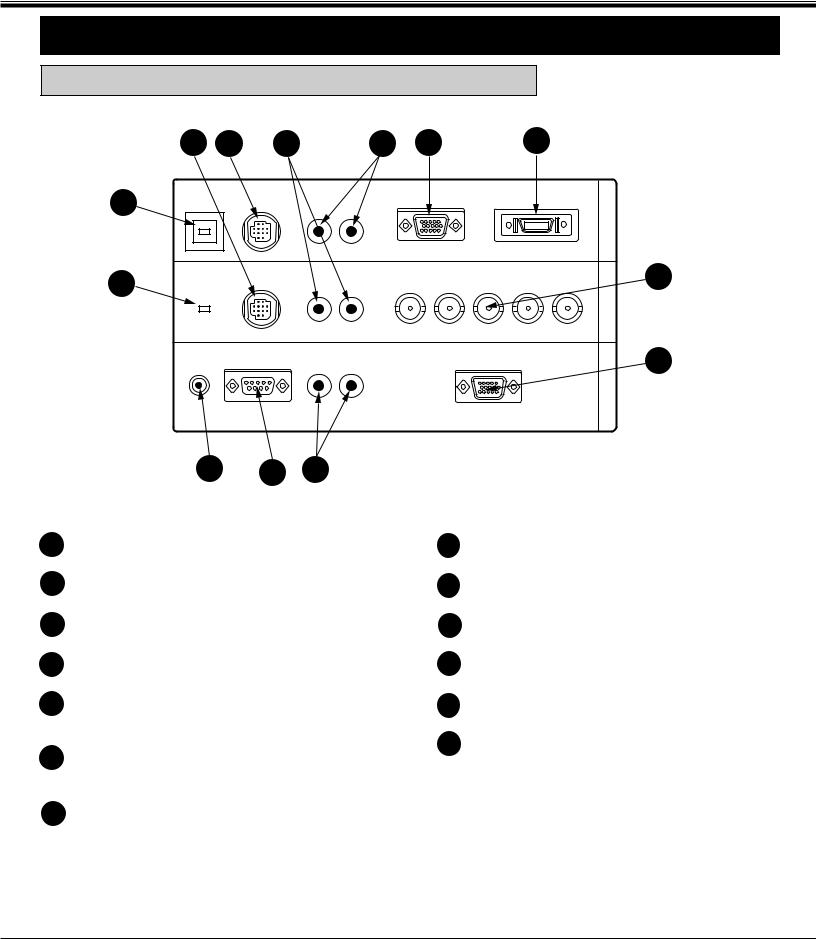
TERMINAL OF THE PROJECTOR
SIDE OF THE PROJECTOR (CONNECT THE COMPUTER)
|
9 |
8 |
6 |
|
5 |
1 |
2 |
10 |
USB 1 CONTROL PORT 1 |
R |
L (MONO) |
|
|
||
|
AUDIO 1 |
ANALOG |
DIGITAL |
||||
11 |
|
USB 2 CONTROL PORT 2 |
AUDIO 2 |
G |
B |
H |
V |
||
|
|
|
|
R |
|||||
|
|
|
|
(MONO) |
|
|
|
|
|
|
|
|
|
|
|
|
|
||
|
|
|
|
|
|
|
|
|
|
|
|
|
|
|
|
|
|
|
|
R/C JACK SERIAL PORT |
AUDIO OUT |
ANALOG RGB |
||
R |
L |
|||
|
||||
|
|
|||
COMPUTER OUT COMPUTER IN-2 COMPUTER IN-1
3
4
1
2
3
4
5
13 12 7
|
8 |
CONNECTOR |
|
|
|
cable to the projector. |
|
COMPUTER INPUT-1 TERMINAL (DIGITAL MDR 20-PIN) |
9 |
CONTROL PORT-2 CONNECTOR |
|
Used to connect a computer to the projector. |
|
Used to connect a mouse cable to the projector. |
|
COMPUTER INPUT-2 JACKS (BNC TYPE x 5) |
10 |
USB PORT-1 CONNECTOR |
|
Used to connect a computer to the projector. |
|
Used to connect a computer to the projector. |
|
MONITOR OUTPUT TERMINAL (ANALOG HDB 15-PIN) |
11 |
USB PORT-2 CONNECTOR |
|
Used to connect a monitor to the projector. |
|
Used to connect a computer to the projector. |
|
COMPUTER AUDIO INPUT-1 JACKS (R and L) |
12 |
SERIAL PORT TERMINAL (DB9) |
|
Used to connect an audio output from the computer to the |
|
Used to connect a computer to the projector. |
|
projector. |
13 |
WIRED REMOTE JACK |
|
COMPUTER AUDIO INPUT-2 JACKS (R and L) |
|||
|
When using the wired remote control, connect the |
||
Used to connect an audio output from the computer to the |
|
remote cable to this jack. |
|
projector. |
|
|
7
Used to connect an audio input from audio equipment to the projector.
10
CONNECTING THE PROJECTOR
SIDE OF THE PROJECTOR (CONNECT THE VIDEO EQUIPMENT)
14
17
20
MONITOR OUT VIDEO IN-2 VIDEO IN-1
15 18
16
VIDEO/Y C/Cb(B-Y) Cr(R-Y) |
S-VIDEO |
AUDIO |
||||||
|
|
|
|
|
|
|
R |
L (MONO) |
|
||||||||
|
|
|
|
|
|
|
|
|
|
|
|
|
|
|
|
|
|
19
VIDEO/Y C/Cb(B-Y) Cr(R-Y) |
S-VIDEO |
AUDIO |
||||||
|
|
|
|
|
|
|
R |
L (MONO) |
|
||||||||
|
|
|
|
|
|
|
|
|
|
|
|
|
|
|
|
|
|
22
VIDEO/Y C/Cb(B-Y) Cr(R-Y) |
S-VIDEO |
AUDIO |
R L
14
15 S-VIDEO INPUT JACK-1
Used to connect a S-VHS video source to the projector.
16 AUDIO INPUT JACKS-1 (R and L)
Used to connect an audio source to the projector.
17 VIDEO INPUT JACKS-2 (BNC TYPE x 3)
Used to connect a video source to the projector.
18 S-VIDEO INPUT JACK-2
Used to connect a S-VHS video source to the projector.
21
19
|
projector. |
20 |
VIDEO MONITOR OUTPUT JACKS (BNC TYPE x 3) |
|
Permits video connection to a monitor. |
21 |
VIDEO MONITOR (S-VIDEO) OUTPUT JACK |
|
Permits S-VHS video connection to a monitor. |
22 |
AUDIO MONITOR OUTPUT JACKS (R and L) |
|
Permits audio connection to a monitor. |
11
CONNECTING THE PROJECTOR
CONNECTING THE COMPUTER
CONNECTING TO THE COMPUTER INPUT 1 TERMINAL (ANALOG HDB 15-PIN)
Personal computers can be connected to the HDB15-pin (VGA) terminal on the projector.
● Connect the computer to these terminals using the VGA cable and VGA/MAC adapter (provided).
CAUTION: For projectors, the VGA cable provided is designed to reduce RFI (Radio Frequency Interference) emissions. For regulatory compliance reasons, this cable must be used and must not be replaced by any other cable.
CONNECTING TO THE COMPUTER INPUT 1 TERMINAL (DIGITAL MDR 20-PIN)
Digital output signal from the computer can be connected to the DIGITAL terminal (MDR 20-pin). When using this input, Graphic Accelerator Board designed for this projector should be installed into your computer and set-up the computer configuration following instruction included in the Graphic Accelerator Board package. Refer to DIGITAL INPUT CONNECTION on page 15 and 17.
CONNECTING TO THE COMPUTER INPUT 2 JACKS (BNC x 5)
Personal computers can be connected to the computer input (Red, Green, Blue, Horiz. Sync. and Vert. Sync.) on the projector.
● Connect the computer to these jacks using the BNC cables (not provided).
CONNECTING TO THE COMPUTER AUDIO INPUT JACKS (1 and 2)
● Connect audio outputs from your computer to these jacks using the audio cable (not provided).
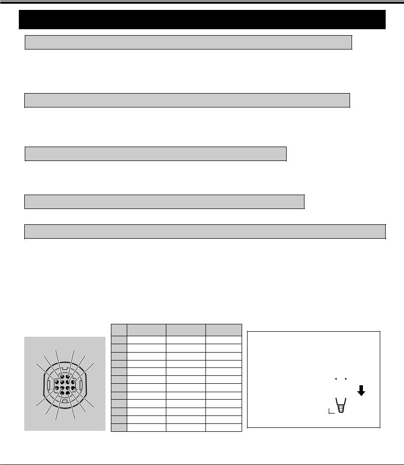
CONNECTING TO THE MULTI-POLE 12-PIN (CONTROL PORT) CONNECTORS (1 and 2)
●When the computer is operated by projector's remote control unit, connect three different type of cables (provided) between projector control port and computer mouse port or serial port.
COMPUTER TYPE |
CABLE |
IBM Compatible computer with PS/2 mouse port. |
Mouse Cable for PS/2 port. |
|
|
IBM Compatible computer with serial port. |
Mouse Cable for Serial port. |
|
|
Apple Macintosh computer with ADB mouse port. |
Mouse Cable for ADB port. |
|
|
■ CONTROL PORT |
|
PS/2 Port |
Serial Port |
ADB Port |
|||
|
|
|
|
|
|||
|
2 |
1 |
|
1 |
–––––––– |
T x D |
–––––––– |
5 |
|
2 |
CLK |
–––––––– |
ADB |
||
|
4 |
|
3 |
DATA |
–––––––– |
–––––––– |
|
6 |
|
|
3 |
||||
|
|
4 |
–––––––– |
–––––––– |
–––––––– |
||
|
|
|
|
||||
|
|
|
|
5 |
–––––––– |
–––––––– |
–––––––– |
|
|
|
|
6 |
–––––––– |
–––––––– |
–––––––– |
|
|
|
|
7 |
–––––––– |
READY |
–––––––– |
|
|
|
|
8 |
–––––––– |
–––––––– |
–––––––– |
10 |
|
|
7 |
9 |
GND |
GND |
GND |
|
8 |
10 |
–––––––– |
–––––––– |
–––––––– |
||
9 |
|
||||||
12 |
|
11 |
–––––––– |
–––––––– |
–––––––– |
||
|
11 |
|
12 |
–––––––– |
–––––––– |
–––––––– |
|
CONTROL PORT CABLE REMOVAL HINT
Disconnect control port cable with following steps.
1. |
Hold the portion (A) |
|
|
|
|
|
|
|||
|
of the connector |
|
|
|
|
|
|
|||
|
|
|
|
|
B |
|||||
|
with one hand. |
|
|
|
|
|||||
|
|
|
|
|||||||
|
|
|
|
|||||||
|
|
|
|
|
|
|
||||
2. |
Pull the portion (B) |
|
|
|
|
|
|
|
|
|
|
|
|
|
|
|
|
|
|
||
A
arrow direction and remove connector.
12
CONNECTING THE PROJECTOR
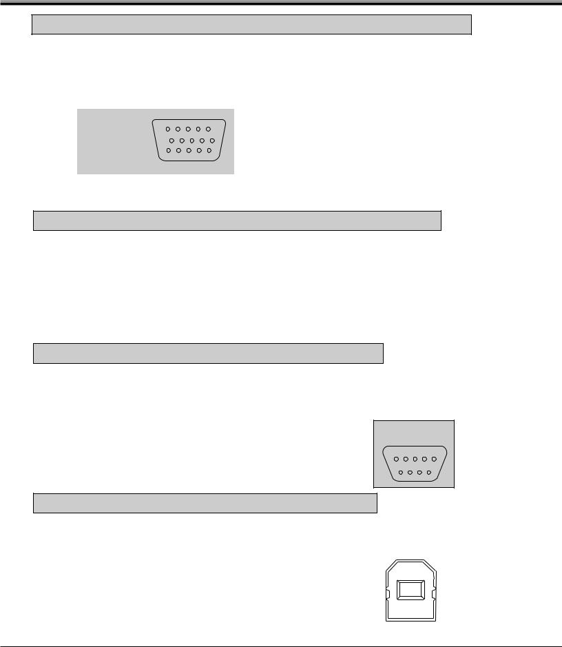
CONNECTING TO THE MONITOR OUTPUT TERMINAL (ANALOG HDB 15-PIN)
This terminal output the information of the selected computer source being viewed on the screen (Computer 1 or Computer 2). When video source ("Video 1" or "Video 2") is selected, this terminal outputs Computer 1 input information.
An external monitor can be connected to the HDB15-pin (VGA) terminal on the projector.
● Connect the monitor to this terminal using the VGA cable (not provided).
|
5 |
4 |
3 |
2 |
1 |
HDB 15-PIN |
10 |
9 |
8 |
7 |
6 |
TERMINAL |
|
|
|
|
|
|
15 14 13 12 11 |
||||
Pin No./Signal |
Pin No./Signal |
||
1 |
Red input |
9 |
Non Connect |
2 |
Green input |
10 |
Ground (Vert. sync.) |
3 |
Blue input |
11 |
Sense 0 |
4 |
Sense 2 |
12 |
Sense 1 |
5 |
Ground (Horiz.sync.) |
13 |
Horiz. sync |
6 |
Ground (Red) |
14 |
Vert. sync |
7 |
Ground (Green) |
15 |
Reserved |
8 |
Ground (Blue) |
|
|
CONNECTING TO THE AUDIO MONITOR OUTPUT (VARIABLE) JACKS
These jacks will contain the audio information of the selected program source being viewed on the screen (Computer 1, Computer 2, Video 1 or Video 2). If you have selected program source Computer 2 the audio signal connected to the Computer 2 audio input jack will be available at the audio monitor output jacks.
Use RCA type audio for connection.
●If the audio input of the audio equipment is stereo, be sure to connect the right and left channels to the respective right and left jacks.
●If the audio input of the audio equipment is monaural, connect it to the left jack.
CONNECTING TO THE SERIAL PORT (DB 9-PIN) TERMINAL
●If you control the projector by computer, you must connect a cable (not provided) from your computer to this terminal.
■SERIAL PORT
DB9-PIN |
|
|
|||
TERMINAL |
|||||
5 |
4 |
|
3 |
2 |
1 |
|
9 |
8 |
7 |
|
6 |
1 |
–––––––– |
2 |
R x D |
3 |
T x D |
4 |
–––––––– |
5 |
Ground |
6 |
–––––––– |
7 |
–––––––– |
8 |
–––––––– |
9 |
–––––––– |
CONNECTING TO THE USB PORT CONNECTORS (1 and 2)
This Projector is designed for connecting with USB Port of the computer or peripheral equipment that is to be standard.
|
|
|
|
|
|
|
|
|
2 |
|
1 |
|
|
1 |
Vcc |
|
|
|
|
|
|
||
|
3 |
|
4 |
|
|
2 |
- Data |
|
|
|
|
3 |
+ Data |
||
|
|
|
|
|
|
||
|
|
|
|
|
|
4 |
Ground |
13

CONNECTING THE PROJECTOR
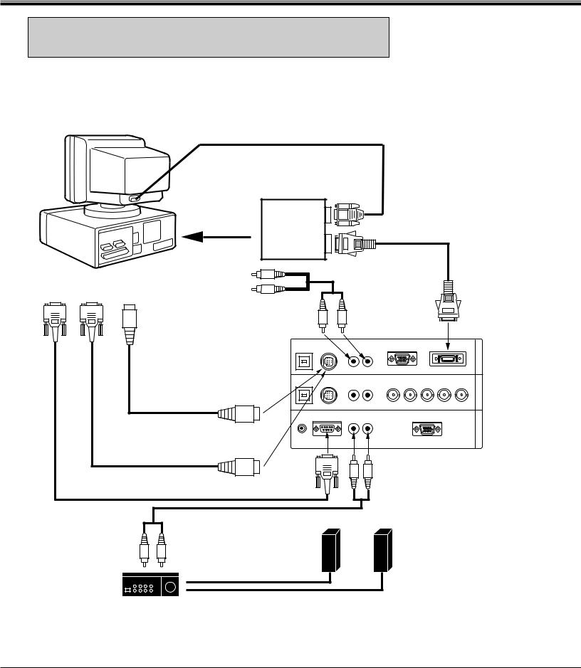
CONNECTING AN IBM-COMPATIBLE DESKTOP COMPUTER
MONITOR CABLE
(NOT PROVIDED)
COMPUTER
COMPUTER |
BNC CABLE x 5 |
(NOT PROVIDED) |
|
OUTPUT |
|
(BNC TYPE x 5) |
|
|
|
|
|
VGA CABLE |
|
|
|
COMPUTER OUTPUT |
(PROVIDED) |
|
|
|
|
|
|
||
|
|
(HDB15-PIN TYPE) |
|
|
|
|
|
|
AUDIO CABLE |
|
|
|
|
|
(NOT PROVIDED) |
|
|
SERIAL PORT |
PS/2 PORT |
COMPUTER |
R |
|
|
|
|
|
|||
AUDIO OUTPUT |
L |
|
|
||
INPUT |
INPUT |
|
|
||
|
|
|
|
||
|
|
|
|
|
COMPUTER |
|
|
COMPUTER |
|
INPUT 1 |
|
|
|
|
(ANALOG) |
||
|
|
AUDIO INPUT 1 or 2 R |
L |
||
|
|
|
|||
|
|
|
USB 1 |
CONTROL PORT 1 |
AUDIO 1 |
|
ANALOG |
|
DIGITAL |
|
IN-1 |
|
|
|
|
|
|
|
R |
|
(MONO) |
|
|
|
|
COMPUTER |
|
|
|
|
|
|
|
|
|
|
|
|
|
|
|
MOUSE CABLE FOR |
USB 2 |
CONTROL PORT 2 |
AUDIO 2 |
R |
G |
B |
H |
V |
IN-2 |
COMPUTER |
|||
|
|
|
|
COMPUTER |
|||||||||
PS/2 PORT |
|
|
|
|
|
(MONO) |
|
|
|
|
|||
|
|
|
|
|
|
|
|
|
|
||||
|
|
|
|
|
|
|
|
|
|
INPUT 2 |
|||
(PROVIDED) |
|
|
|
|
|
|
|
|
|
|
|||
|
|
|
|
|
|
|
|
|
|
|
|||
|
|
|
|
|
|
|
|
|
|
|
|
|
|
|
|
|
R/C JACK |
SERIAL PORT |
AUDIO OUT |
|
ANALOG RGB |
|
|
OUT |
MONITOR |
||
|
|
|
R |
L |
|
|
|
|
|||||
|
|
|
|
|
|
|
|
|
|
COMPUTER |
|||
|
|
|
|
|
|
|
|
|
|
|
|
||
MOUSE CABLE FOR |
CONTROL PORT |
|
|
|
|
|
|
|
|
|
OUTPUT |
||
OUTPUT 1 or 2 |
|
|
|
|
|
|
|
|
|
|
|||
SERIAL PORT |
|
|
|
|
|
|
|
|
|
|
|
|
|
(PROVIDED) |
|
|
|
|
|
|
|
|
|
|
|
|
|
|
|
|
SERIAL |
|
|
|
|
|
|
|
|
|
|
SERIAL PORT CABLE |
|
|
PORT |
|
|
|
|
|
|
|
|
|
|
(NOT PROVIDED) |
|
|
OUTPUT |
|
|
|
|
|
|
|
|
|
|
|
AUDIO CABLE |
|
|
|
|
COMPUTER |
|
|
|
|
|
||
|
|
|
|
|
AUDIO OUTPUT |
|
|
|
|
||||
|
(NOT PROVIDED) |
|
|
|
|
|
|
|
|
|
|
|
|
AUDIO |
|
SPEAKER |
|
|
|
|
|
|
|
|
|
|
|
INPUT |
|
|
|
|
|
|
|
|
|
|
|
|
|
|
|
OUT |
|
|
|
|
|
|
|
|
|
|
|
L |
R |
L |
Speaker (L) |
|
|
|
|
Speaker (R) |
|
|
|
|
|
|
|
|
|
|
|
|
|
|
|
||||
|
|
|
|
|
|
|
|
|
|
|
|
|
|
Amp. |
|
R |
|
|
|
|
|
|
|
|
|
|
|
|
|
|
|
|
|
|
|
|
|
|
|
|
|
NOTE: When connecting the cable, the power cords of both the projector and the external equipment should be disconnected from AC outlet. Turn the projector and peripheral equipment on before the computer is switched on.
14
CONNECTING THE PROJECTOR
CONNECTING AN IBM-COMPATIBLE DESKTOP COMPUTER (DIGITAL INPUT CONNECTION)
NOTE:
Before using with digital connection, install (Plug in) Graphic Accelerator Board (included within projector) into PCI bus slot of the computer and set up the computer following instructions in the Graphic Accelerator Board package.
COMPUTER
|
MONITOR CABLE |
|
|
|
(NOT PROVIDED) |
|
|
GRAPHIC |
ANALOG |
|
|
ACCELERATOR |
DIGITAL FLAT |
||
BOARD |
OUTPUT |
||
PANEL CABLE |
|||
|
|
||
|
DIGITAL |
(PROVIDED) |
|
|
|
||
INSTALL (PLUG) |
OUTPUT |
|
INTO PCI BUS SLOT
SERIAL PORT |
PS/2 PORT |
COMPUTER |
R |
AUDIO CABLE |
||
AUDIO OUTPUT |
L |
(NOT PROVIDED) |
||||
INPUT |
INPUT |
|||||
|
|
|
|
|||
|
|
|
|
|
COMPUTER |
|
|
|
|
COMPUTER |
|
INPUT 1 |
|
|
|
|
AUDIO INPUT 1 R |
L |
(DIGITAL) |
|
|
|
USB 1 |
CONTROL PORT 1 |
AUDIO 1 |
|
ANALOG |
|
DIGITAL |
|
IN-1 |
|
|
|
|
|
R |
|
(MONO) |
|
|
|
|
COMPUTER |
|
|
|
|
|
|
|
|
|
|
|
|
MOUSE CABLE FOR |
USB 2 |
CONTROL PORT 2 |
AUDIO 2 |
R |
G |
B |
H |
V |
IN-2 |
||
|
|
R |
L |
COMPUTER |
|||||||
PS/2 PORT |
|
|
(MONO) |
|
|
|
|
||||
|
|
|
|
|
|
|
|
|
|||
(PROVIDED) |
|
|
|
|
|
|
|
|
|
||
|
|
|
|
|
|
|
|
|
|
|
|
|
|
R/C JACK |
SERIAL PORT |
AUDIO OUT |
|
ANALOG RGB |
|
|
OUT |
||
|
|
R |
L |
|
|
|
|
||||
|
|
|
|
|
|
|
|
|
COMPUTER |
||
MOUSE CABLE FOR |
CONTROL PORT |
|
|
|
|
|
|
|
|
|
|
SERIAL PORT |
OUTPUT 1 |
|
|
|
|
|
|
|
|
|
|
|
|
|
|
|
|
|
|
|
|
||
(PROVIDED) |
|
|
|
|
|
|
|
|
|
|
|
SERIAL PORT CABLE |
|
SERIAL |
|
|
|
|
|
|
|
|
|
|
PORT |
|
|
|
|
|
|
|
|
|
|
(NOT PROVIDED) |
|
OUTPUT |
|
|
|
|
|
|
|
|
|
|
|
|
|
|
COMPUTER |
|
|
|
|
||
|
AUDIO CABLE |
|
|
|
AUDIO OUTPUT |
|
|
|
|||
|
|
|
|
|
|
|
|
|
|
|
|
|
(NOT PROVIDED) |
|
|
|
|
|
|
|
|
|
|
AUDIO
INPUT |
|
SPEAKER |
|
|
L |
R |
OUT |
|
|
|
Speaker (L) |
Speaker (R) |
||
|
|
L |
||
|
|
|
|
R
Amp.
NOTE: When connecting the cable, the power cords of both the projector and the external equipment should be disconnected from AC outlet. Turn the projector and peripheral equipment on before the computer is switched on.
15
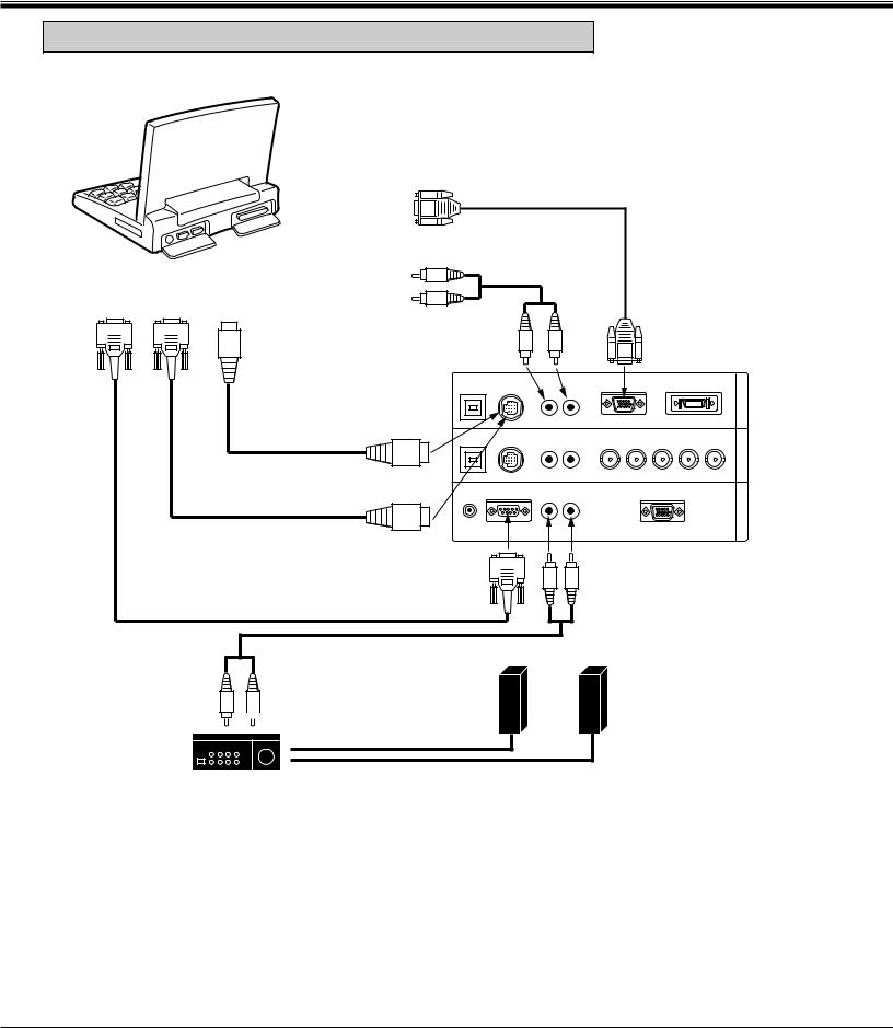
CONNECTING THE PROJECTOR
CONNECTING AN IBM-COMPATIBLE LAPTOP COMPUTER
COMPUTER
|
|
|
|
|
|
VGA CABLE |
|
|
|
COMPUTER OUTPUT |
|
|
(PROVIDED) |
|
|
|
|
|
|
|
|
||
|
|
(DB15-PIN TYPE) |
|
|
|
|
|
|
|
|
R |
AUDIO CABLE |
|
||
|
|
COMPUTER |
|
(NOT PROVIDED) |
|
||
SERIAL PORT |
PS/2 PORT |
|
|
|
|
|
|
AUDIO OUTPUT |
|
|
|
|
|
||
INPUT |
INPUT |
|
|
|
|
|
|
|
|
|
|
|
|
||
|
|
|
L |
|
|
|
|
|
|
|
COMPUTER |
|
|
|
COMPUTER |
|
|
|
|
|
|
INPUT 1 |
|
|
|
|
AUDIO INPUT 1 |
R |
|
L |
|
|
|
|
|
(ANALOG) |
|||
|
|
|
|
|
|
|
|
|
|
|
USB 1 |
CONTROL PORT 1 |
|
ANALOG |
DIGITAL |
|
|
|
|
|
R |
(MONO) |
|
|
MOUSE CABLE FOR |
|
|
|
|
|
|
|
PS/2 PORT |
|
|
|
|
|
|
|
(PROVIDED) |
USB 2 |
CONTROL PORT 2 AUDIO 2 |
|
|||
|
|
|
B H V |
||||
|
|
|
|
|
R |
R G |
|
|
|
|
|
|
L (MONO) |
|
|
|
|
CONTROL PORT |
|
|
|
|
|
|
|
OUTPUT 1 |
R/C JACK |
SERIAL PORT |
AUDIO OUT |
ANALOG RGB |
|
|
|
|
R |
L |
|||
|
|
|
|
|
|||
|
|
|
|
|
|
||
MOUSE CABLE FOR |
|
|
|
|
|
||
SERIAL PORT |
|
|
|
|
|
|
|
(PROVIDED) |
|
SERIAL |
|
|
|
|
|
|
|
|
|
|
COMPUTER |
||
|
|
|
PORT |
|
|
||
SERIAL PORT CABLE |
|
|
|
AUDIO OUTPUT |
|||
|
OUTPUT |
|
|
||||
(NOT PROVIDED) |
|
|
|
|
|
|
|
AUDIO CABLE (NOT PROVIDED)
SPEAKER
OUT
R |
|
|
|
L |
Speaker (L) |
Speaker (R) |
|
L
AUDIO
INPUT
R
Amp.
COMPUTER OUT COMPUTER IN-2 COMPUTER IN-1
NOTE: When connecting the cable, the power cords of both the projector and the external equipment should be disconnected from AC outlet. Turn the projector and peripheral equipment on before the computer is switched on.
16
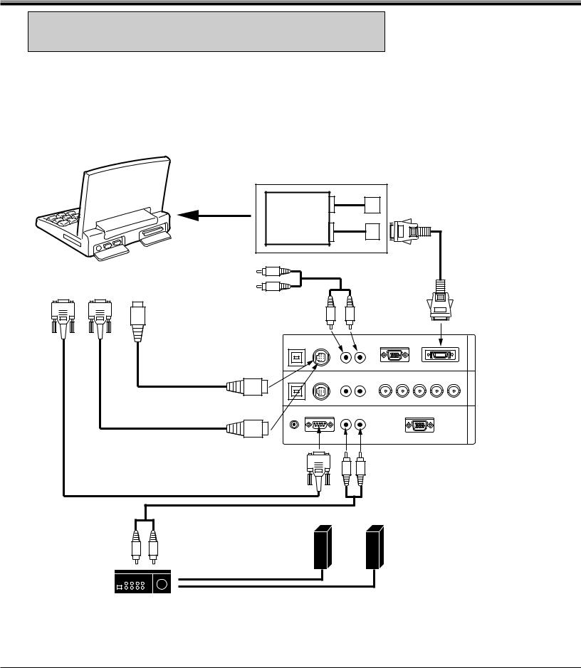
CONNECTING THE PROJECTOR
CONNECTING AN IBM-COMPATIBLE LAPTOP COMPUTER (DIGITAL INPUT CONNECTION)
NOTE: This connection need optionally sold Graphic Accelerator PC card. For this information, contact to your authorized dealer.
COMPUTER
SERIAL PORT |
PS/2 PORT |
INPUT |
INPUT |
Before using with digital connection, install (Plug in) Graphic Accelerator PC card into card bus slot of the computer and set up the computer following instructions in the Graphic Accelerator PC card package.
GRAPHIC
ACCELERATOR
PC CARD
INSTALL (PLUG)
INTO PC CARD
BUS SLOT ANALOG
OUTPUT
|
DIGITAL |
|
|
OUTPUT |
|
|
DIGITAL FLAT |
|
R |
PANEL CABLE |
|
(PROVIDED) |
||
COMPUTER |
AUDIO CABLE |
|
(NOT PROVIDED) |
||
AUDIO OUTPUT |
||
|
L
|
COMPUTER |
R |
|
|
L |
|
|
AUDIO INPUT 1 |
|
|
|
|
|
|
USB 1 CONTROL PORT 1 |
|
|
ANALOG |
DIGITAL |
|
MOUSE CABLE FOR |
|
|
R |
|
(MONO) |
|
|
|
|
|
|
|
|
PS/2 PORT |
|
|
|
|
|
|
(PROVIDED) |
|
|
|
|
|
|
|
USB 2 |
CONTROL PORT 2 AUDIO 2 |
R G B |
H V |
||
|
|
|
R |
L |
||
|
|
|
(MONO) |
|
||
CONTROL PORT |
|
|
|
|
|
|
OUTPUT 1 |
R/C JACK |
SERIAL PORT |
|
|
ANALOG RGB |
|
|
|
|
AUDIO OUT |
|
||
|
|
|
R |
L |
|
|
MOUSE CABLE FOR |
|
|
|
|
|
|
SERIAL PORT |
|
|
|
|
|
|
(PROVIDED) |
SERIAL |
|
|
|
|
|
|
|
|
|
COMPUTER |
|
|
|
PORT |
|
|
|
|
|
|
|
|
|
AUDIO OUTPUT |
|
|
SERIAL PORT CABLE |
OUTPUT |
|
|
|
|
|
|
|
|
|
|
||
(NOT PROVIDED) |
|
|
|
|
|
|
COMPUTER OUT COMPUTER IN-2 COMPUTER IN-1
COMPUTER INPUT 1 (DIGITAL)
AUDIO CABLE (NOT PROVIDED)
|
SPEAKER |
|
R |
OUT |
|
L |
Speaker (R) |
|
|
Speaker (L) |
L
AUDIO
INPUT
R
Amp.
NOTE: When connecting the cable, the power cords of both the projector and the external equipment should be disconnected from AC outlet. Turn the projector and peripheral equipment on before the computer is switched on.
17
CONNECTING THE PROJECTOR
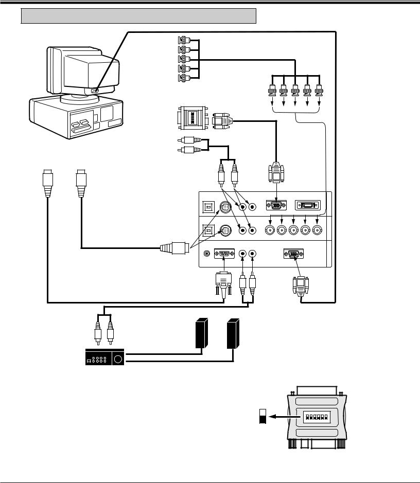
CONNECTING A MACINTOSH DESKTOP COMPUTER
COMPUTER |
BNC CABLE x 5 |
MONITOR CABLE |
|
|
(NOT PROVIDED) |
||
COMPUTER |
(NOT PROVIDED) |
||
|
|||
OUTPUT |
|
|
|
(BNC TYPE x 5) |
|
|
|
|
|
|
|
VGA/MAC ADAPTER |
|
|
|
|
|
|
|
|
||
|
|
|
|
|
(PROVIDED) |
|
|
|
|
|
|
|
|
|
|
|
|
|
COMPUTER |
5 6 |
|
|
|
|
|
|
|
|
|
||
|
|
|
OUTPUT |
|
|
3 4 |
|
|
|
|
|
|
|
|
|
|
|
|
|
ON |
1 2 |
|
|
|
|
|
|
|
|
|
|
|
|
|
|
|
|
|
|
|
|
|
|
|
|
||
|
|
COMPUTER |
|
R |
|
|
|
|
VGA CABLE |
|
|
|
|||
|
|
|
|
|
|
|
|
(PROVIDED) |
|
|
|
||||
|
|
AUDIO OUTPUT |
|
L |
|
|
|
|
|
|
|
||||
ADB PORT |
ADB PORT |
|
|
|
|
|
|
|
|
|
|
|
|||
|
|
|
|
|
|
|
|
|
|
|
|
|
|||
|
|
|
|
|
|
|
|
|
|
|
|
|
|
||
INPUT |
INPUT |
|
|
|
AUDIO CABLE |
|
|
|
|
|
|
|
|
|
|
|
|
|
|
|
|
|
|
|
COMPUTER |
|
|
||||
|
|
|
|
|
(NOT PROVIDED) |
|
|
|
|
|
|
||||
|
|
|
|
|
|
|
|
|
INPUT 1 |
|
|
|
|||
|
|
|
|
|
|
|
|
|
|
|
|
|
|
||
|
|
|
|
|
|
R |
|
L |
|
|
(ANALOG) |
|
|
|
|
|
|
|
COMPUTER |
|
|
|
|
|
|
|
|
||||
|
|
|
|
|
|
|
|
|
|
|
|
|
|||
|
|
|
AUDIO OUTPUT1 or 2 |
|
|
|
|
|
|
|
|
-1 |
|
||
|
|
|
|
|
|
USB 1 CONTROL PORT 1 |
AUDIO 1 |
ANALOG |
|
DIGITAL |
|
IN |
|
||
|
|
|
|
|
|
|
|
R |
L (MONO) |
|
|
|
|
COMPUTER |
|
|
|
|
|
|
|
|
|
|
|
|
|
|
|
|
|
|
|
|
|
|
|
USB 2 CONTROL PORT 2 |
AUDIO 2 |
G |
B |
H |
V |
IN-2 |
COMPUTER |
||
|
MOUSE CABLE FOR |
|
|
|
|
R |
R |
COMPUTER |
|||||||
|
|
|
|
|
L (MONO) |
|
|
|
|
||||||
|
|
|
|
|
|
|
|
|
|
|
|||||
|
ADB PORT |
|
|
|
|
|
|
|
|
|
|
|
|
INPUT 2 |
|
|
(PROVIDED) |
|
|
|
|
|
|
|
|
|
|
|
|
||
|
|
|
|
|
|
|
|
|
|
|
|
|
|
||
|
|
|
|
|
|
R/C JACK |
SERIAL PORT |
AUDIO OUT |
|
ANALOG RGB |
|
|
OUT |
|
|
|
|
|
|
|
|
R |
L |
|
|
|
MONITOR |
||||
|
|
|
|
|
|
|
|
|
|
|
|
COMPUTER |
|||
|
|
|
|
|
|
|
|
|
|
|
|
|
|
||
|
|
|
CONTROL PORT |
|
|
|
|
|
|
|
|
OUTPUT |
|||
|
|
|
|
|
|
|
|
|
|
|
|
||||
|
|
|
OUTPUT 1 or 2 |
|
|
|
|
|
|
|
|
|
|
||
|
|
|
|
|
SERIAL |
|
|
|
|
|
|
|
|
|
|
SERIAL PORT CABLE |
|
|
|
PORT |
|
|
|
|
|
|
|
|
|
||
|
|
|
OUTPUT |
|
|
|
|
|
|
|
|
|
|||
(NOT PROVIDED) |
|
|
|
|
|
|
|
|
|
|
|
|
|
|
|
|
|
AUDIO CABLE |
|
|
|
|
|
COMPUTER |
|
|
|
|
|
||
|
|
|
|
|
|
|
AUDIO OUTPUT |
|
|
|
|
||||
|
AUDIO |
(NOT PROVIDED) |
|
|
|
|
|
|
|
|
|
|
|
||
|
INPUT |
|
SPEAKER |
|
|
|
|
|
|
|
|
|
|
|
|
|
R |
L |
|
|
|
|
|
|
|
|
|
|
|
|
|
|
OUT |
Speaker (L) |
|
|
Speaker (R) |
|
|
|
|
|
|||||
|
|
|
L |
|
|
|
|
|
|
|
|||||
|
Amp. |
|
|
|
|
|
|
|
|
|
|
|
|
|
|
|
|
|
|
|
|
|
|
|
|
|
|
|
|
|
|
|
|
|
R |
|
|
|
|
|
|
|
|
|
|
|
|
Set the dip switches as shown in the table below depending on the RESOLUTION MODE that you want to use before you turn on the projector and computer.
RESOLUTION MODE |
SW1 |
SW2 |
SW3 |
SW4 |
SW5 |
SW6 |
13" MODE (640 x 480) |
ON |
ON |
OFF |
OFF |
OFF |
OFF |
16" MODE (832 x 624) |
OFF |
ON |
OFF |
ON |
OFF |
OFF |
19" MODE (1024 x 768) |
OFF |
ON |
ON |
OFF |
OFF |
OFF |
21" MODE (1152 x 870) |
ON |
ON |
ON |
ON |
OFF |
OFF |
|
|
|
|
|
|
|
VGA/MAC ADAPTER
SW1 ~ SW6
ON
ON
1 2 3 4 5 6
OFF
NOTE: When connecting the cable, the power cords of both the projector and the external equipment should be disconnected from AC outlet. Turn the projector and peripheral equipment on before the computer is switched on.
18
 Loading...