

Page 1
PLASMA MONITORSERVICE MANUAL
FILE NO.
Model No. PDP-42WV1
PDP-42WV1S
(EUROPE, ASIA)
PDP42WV1A
PDP-42WV1AS
(U.S.A.)
ORIGINAL VERSION
PRODUCT CODE
1 110 017 00 PDP-42WV1, J3TF
1 110 023 00 PDP-42WV1A, J3TFA
1 110 043 00 PDP-42WV1S, J3TG
1 110 044 00 PDP-42WV1AS, J3TGA
REFERENCE NO. SM5110505-00
Chassis No. PDP-42WV1-00
(PDP-42WV1)
NOTE: Match the Chassis No. on the
unit’s back cover with the Chassis
No. in the Service Manual.
If the Original Version Service
Manual Chassis No. does not
match the unit’s, additional
Service Literature is required. You
must refer to “Notices” to the
Original Service Manual prior to
servicing the unit.
CONTENTS
Pages
SAFETY INSTRUCTIONS --------------------------------------------------------------------- 2
TECHNICAL SPECIFICATIONS ------------------------------------------------------------- 3
DIMENSIONS AND OPTIONS---------------------------------------------------------------- 3
BATTERY REPLACEMENT------------------------------------------------------------------- 4
MECHANICAL DISASSEMBLIES ------------------------------------------------------- 5 - 8
ADJUSTMENT------------------------------------------------------------------------------ 9 - 16
CIRCUIT BLOCK DIAGRAM----------------------------------------------------------------- 17
POWER SUPPLY LINES--------------------------------------------------------------------- 18
POWER FAIL CIRCUIT----------------------------------------------------------------- 19 - 21
TROUBLESHOOTING ------------------------------------------------------------------------ 22
CONTROL PORT FUNCTIONS ------------------------------------------------------ 23 - 24
PIN DESCRIPTION OF DIODE, TRANSISTOR AND IC----------------------------- 25
PARTS LIST ------------------------------------------------------------------------------- 26 - 43
PARTS DESCRIPTION AND READING IN SCHEMATIC DIAGRAM ------------ 44
SCHEMATIC DIAGRAMS---------------------------------------------------------- A-1 - A-15
PRINTED WIRING BOARD DIAGRAMS-------------------------------------A-16 - A-24
Chassis No. PDP-42WV1S-00
(PDP-42WV1S)
Chassis No. J3T -42WV1A00
(PDP-42WV1A)
Chassis No. J3T -42WV1AS00
(PDP-42WV1AS)
Page 2
-2-
■ Safety Instructions
Product safety should be considered when a component replacement is made in any area of the monitor.
Components indicated by mark in the parts list and the schematic diagram designate components in
which safety can be of special significance. It is, therefore, particularly recommended that the replacement of
there parts must be made by exactly the same parts.
PRODUCT SAFETY NOTICE
SAFETY PRECAUTIONS
WARNING : TO REDUCE THE RISK OF FIRE OR ELECTRIC SHOCK, DO NOT EXPOSE THIS APPLIANCE TO
RAIN OR MOISTURE.
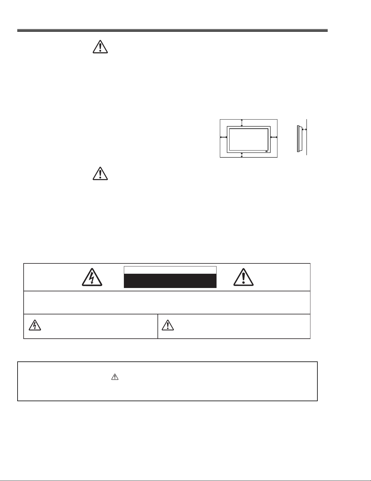
● This Plasma Monitor should be set in the way indicated. If not, it may result in a fire hazard.
● Take appropriate space on the top, sides and rear of the Plasma Monitor cabinet for allowing air circulation and
cooling the Plasma Monitor. Minimum clearance must be maintained. If the Plasma Monitor is to be built into
a compartment or similarly enclosed, the minimum distances must
be maintained. Do not cover the ventilation slot on the Plasma
Monitor. Heat build-up can reduce the life of your Plasma
Monitor, and can also be dangerous.
● If the Plasma Monitor is not to be used for an extended time,
unplug the Plasma Monitor from the power outlet.
READ AND KEEP THIS OWNER'S MANUAL FOR LATER USE.
CAUTION IN INSTALLING
SIDE, TOP and BOTTOM
10 cm
10 cm
6 cm
REAR
3 cm
10 cm
Handle the
●
Locate set away from heat, excessive dust, and direct sunlight.
●
For correct installation and mounting it is strongly recommended to use a trained, authorized dealer. Failure to
●
follow correct mounting procedures could result in damage to the equipment or injury to the installer.
Plasma
Monitor carefully when installing it and do not drop.
NOTE :
When Plasma Monitor is not used for a long period of time, unlighting dots may be observed. This is caused by
characteristic of the Plasma Monitor. If this occurs, turn the Plasma Monitor on and leave it on about 1 hour. These
dots will gradually disappear.
CAUTION
RISK OF ELECTRIC SHOCK
DO NOT OPEN
CAUTION : TO REDUCE THE RISK OF ELECTRIC SHOCK, DO NOT REMOVE COVER (OR BACK). NO USER-
SERVICEABLE PARTS INSIDE. REFER SERVICING TO QUALIFIED SERVICE PERSONNEL.
THIS SYMBOL INDICATES THAT DANGEROUS
VOLTAGE CONSTITUTING A RISK OF ELECTRIC
SHOCK IS PRESENT WITHIN THIS UNIT.
THIS SYMBOL INDICATES THAT THERE ARE IMPORTANT
OPERATING AND MAINTENANCE INSTRUCTIONS IN THE
OWNER'S MANUAL WITH THIS UNIT.
Page 3
-3-
■ Dimensions and Options
MEASUREMENT OPTIONS
Size in mm (inch)
The products listed below are optionally supplied.
When ordering these products, give name and Type No. to
sales dealer.
Speaker unit KA-SX-42V (R and L)
(Color: Black)
KA-SX-42VS (R and L)
(Color: Silver)
Table top stand KA-TD-42V
Tilt mount unit KA-TI-42V
Wall mount unit KA-WA-42V
Contact the sales dealer for other available options.
■ Technical Specifications
Screen Diagonal
42V
Product name
Multimedia Plasma Monitor
Panel type
Plasma Display Panel (16 x 9)
Display area
920 mm (W) x 518 mm (H)
Resolution / Color
852 x 480 pixels
PC Interface
RGB
Capability
Up to SXGA
Plug & Play
VESA DDC2B
Power Management
VESA DPMS
Audio Amp
10W + 10W (8 Ω)
Terminals
PC IN
RGB (D-SUB 15pin)
AUDIO R / L (Stereo Mini jack)
WIRED RC IN / OUT
Mini Jack
EXT. SP OUT
R and L, 10W (8 Ω), Push type
POWER SUPPLY
AC 200 - 240V 50/60 Hz (PDP-42WV1/PDP-42WV1S)
AC 100 - 120V 50/60 Hz (PDP-42WV1A/PDP-42WV1AS)
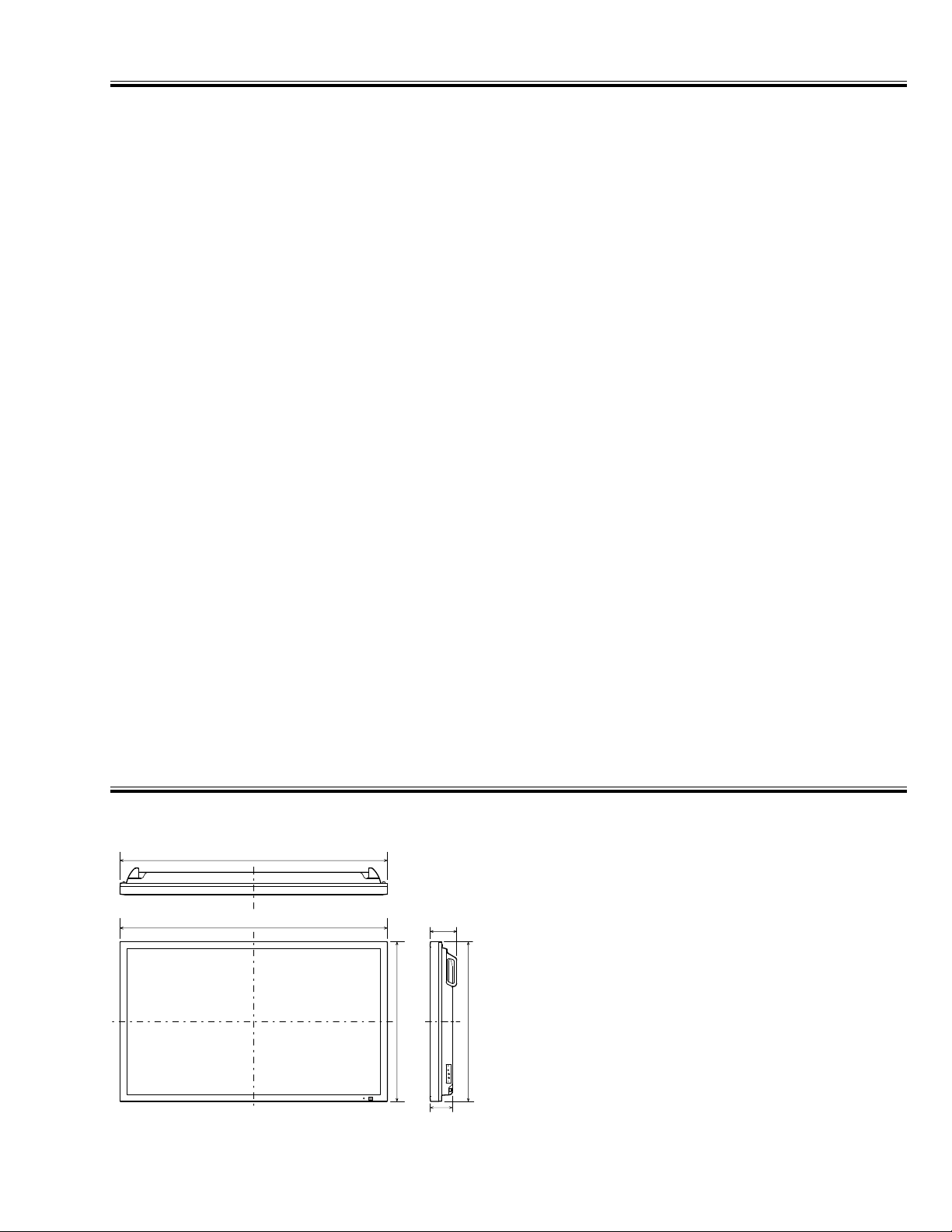
DIMENSION (W x H x D)
1022 x 610 x 85 mm
(
402.4" x 240.2" x 33.5" )
(not including handles)
WEIGHT (NET)
29.8 kg
(
65.7 lbs )
(Plasma Monitor only)
Regulations
FCC CLASS-A, UL (PDP-42WV1A/PDP-42WV1S), CE (PDP-42WV1/PDP-42WV1S)
Environmental Considerations
Operating Temperature
0˚C ~ 40˚C (32˚F ~ 104˚F )
Humidity
20 ~ 80%
Storage Temperature
-10˚C ~ 50˚C (14˚F ~ 122˚F)
Humidity
20 ~ 80 %
Accessories
Owner’s Manual
AC Power Cord
Wired/Wireless Remote Control Transmitter and Batteries
Remote Control Cable
Ferrite Cores (x2)
1022
(40.2)
1022
(40.2)
610
(24.0)
(3.4)
102
(4.0)
85
610
(24.0)
Page 4
-4-
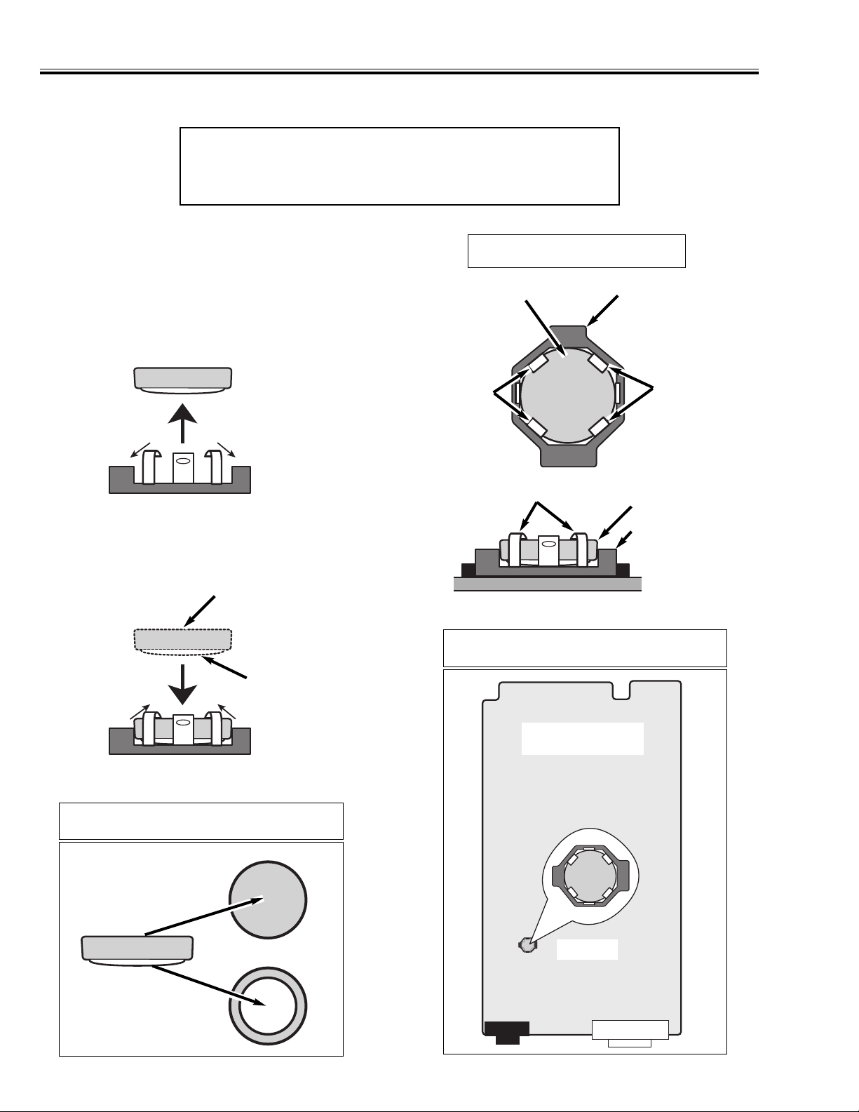
■ Battery Replacement
This Plasma Monitor is used a battery for Clock Function.
■ Battery Replacement
The battery is fixed to Main Board with Battery
Holder.
CAUTION
Danger of explosion if battery is incorrectly replaced.
Replace only with the same or equivalent type.
Battery Holder
Battery
Hook
Hook
Battery
Battery Holder
Hook
Main Board
Location of Battery
(+) Side
(-) Side
(1) Remove the battery from battery holder to bent
hooks slightly.
(2) Mount a new battery by correct polarity and
bent hooks back.
Polarity of Battery
(+) Side
(-) Side
Main Board
Battery
Parts No.: 645 059 8302
Page 5
C
-5-
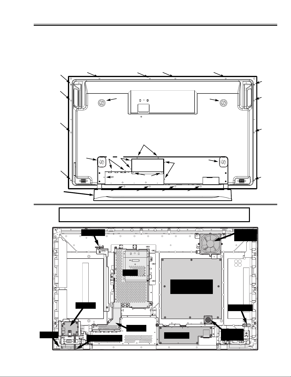
■ Mechanical Disassemblies
1. Cabinet Back Removal (Fig. 1)
Remove screws (A, B, C) and remove Cabinet Back as Fig. 1.
Note: For removal Option Slot Cocer, remove screws (D) and slide down.
A (4pcs: 8X20), B (9pcs: 3X6), C (16pcs: Special Screw), D (2pcs: 3X6)
Fig. 1
A
A
A
A
B
B
B
B
B
C
C
C
C
C
C C
C
C
C
C
C
C C C
Option
Stand
D
Option
Slot Cover
Location of Circuit Board and Electric Parts
Main
Power
Main Power
Module
Jack-A
Jack-B
Sensor-A
Sensor-B
Fan
(FN1901)
Fan
(FN1903)
Control
Membrane SW
Note: Control Board and Membrane Switch are fixed at Cabinet Front.
Fig. 2
Page 6
-6-
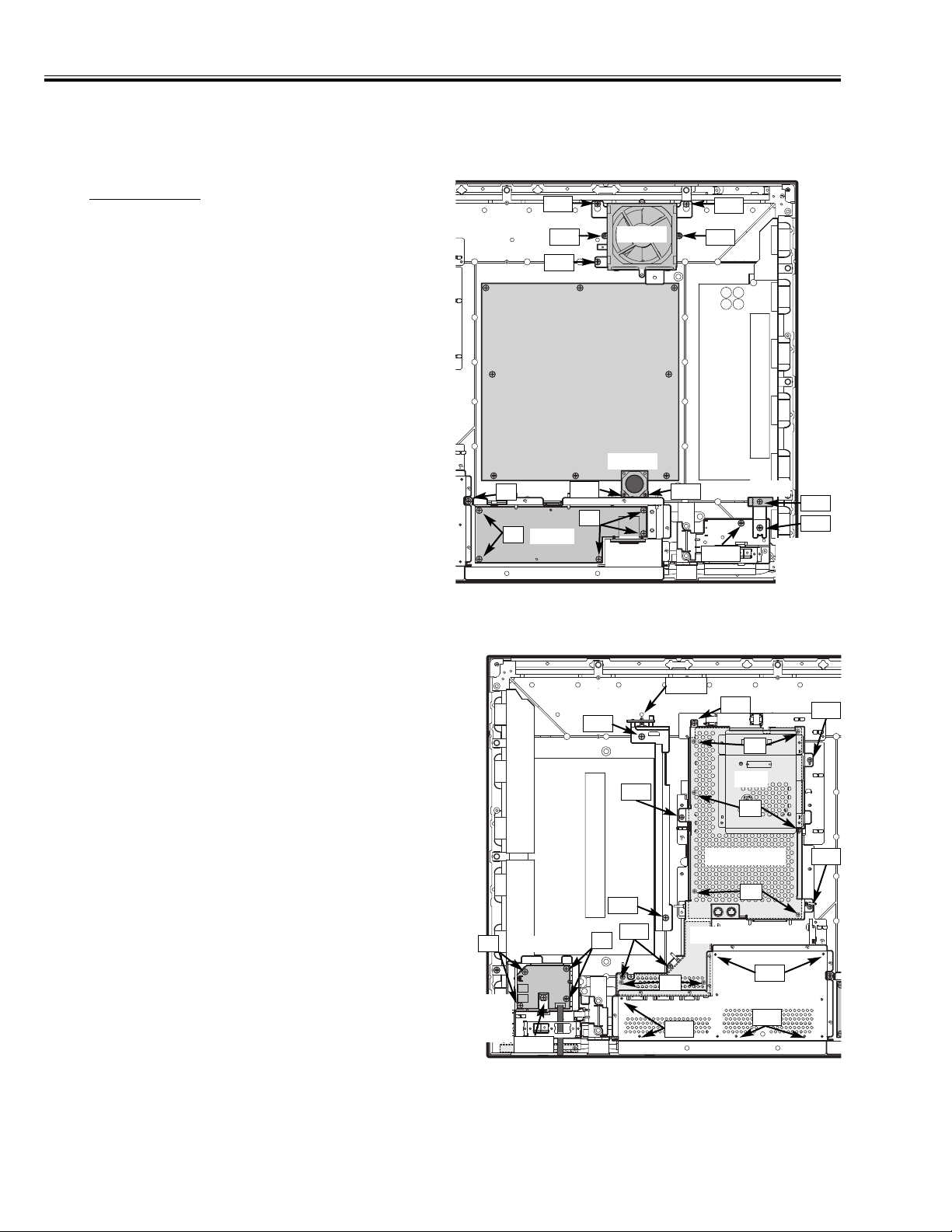
Mechanical Disassemblies
2. Chassis Removal
[ATTENTION]
This PDP monitor is used the different kind of screw.
Using correct screw is needed to avoid the damage.
2-1 Fans Removal (Fig. 3)
FN1901
1) Remove screws (FN1: 3pcs) and take Fan (FN1901)
with the holder off.
2) Remove screws (FN2: 2pcs) and take Fan from the
holder.
FN1903
1) Remove screws (FN3: 2pcs) and take Fan (FN1903)
off.
2-2 Power Board Removal (Fig. 3)
1) Remove screws (P1: 5pcs) and take Power Board
off.
✽ Remove screw (P2: 1pc) and take Power Board with
the holder off.
2-3 Sensor-A Board Removal (Fig. 3)
1) Remove screw (SA1: 1pc) and take Sensor-A Board
off.
✽ Remove screw (SA2: 1pc) and take Sensor-A Board
with the plate off.
✽✽ Remove screw (STB1: 1pc) and take Speaker
Terminal Base (R) with the Sensor-A Board and
holder off.
2-4 Sensor-B Board Removal (Fig. 4)
1) Remove Sensor-B Board from the Hook.
✽ Remove screws (SB1: 2pcs) and take Sensor-B
Board with the plate off.
2-5 Jack-B Board Removal (Fig. 4)
1) Remove screw (B1: 4pcs) and take Jack-B Board
with the holder off.
✽ Remove screw (STB2: 1pc) and take Speaker
Terminal Base (R) with the Jack-B Board and holder
off.
2-6 Main and Jack-A Boards Removal (Fig. 4)
1) Remove screws (SP1: 6pcs) and take Shield Plate
(for Main and Jack-A board) off.
2) Remove screws (M1: 6pcs) and take Main board off.
3) Remove screws (TP1: 6pcs) and nut-screws of the
terminals on Jack-A board (6pcs), and take Terminal
Plate off.
4) Remove screws (A1: 2pcs) and take Jack-A board
off.
Note: If the cable is fixed by ferrite core or CV band
(fixer), remove it as the need arises. After servicing, it is necessary to be fixed again to previous
position.
Power
Sensor-A
FN1901
FN1903
Speaker
Terminal
Base(R)
SA1
SA2
STB1
FN2
FN2
FN1
FN1
FN1
FN3
FN3
P2
P1
P1
Fig. 3
Fig. 4
Sensor-B
SB1
Hook
Speaker
Terminal
Base(L)
STB2
Jack-B
B1
B1
SB1
Jack-A
Main
Shield Plate
Terminal Plate
SP1
SP1
SP1
SP1
SP1
A1
M1
M1
M1
TP1
TP1
TP1
Page 7
-7-
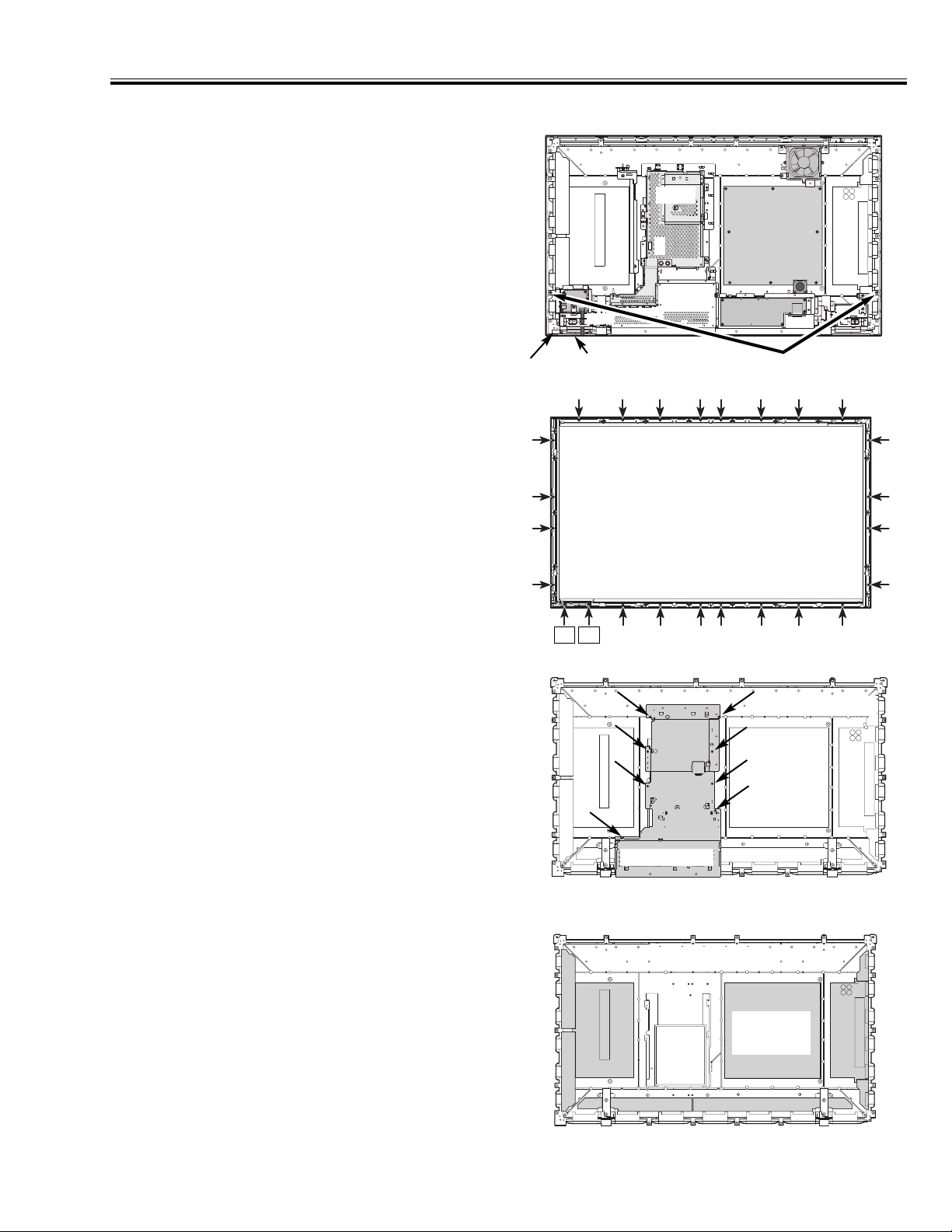
3. Cabinet Front and Optical Filter Removal
4. Panel Module Removal
Fig. 6
1) Proceed 1 to 3 to remove Cabinet Back,
Chassis and Cabinet Front.
2) Remove screws (8pcs) of Chassis Base and take it
from Panel Module.
(Fig. 7)
Note: Units of Fig.8 are included with Panel for PDP
Module. Do not remove them from Panel. For
removal of Panel, it is necessary to change
these all units together. Main Power Module is
included with Panel Module too. Do not
remove Main Power Module from Panel Module.
Mechanical Disassemblies
Fig. 5
Mounting Filter Plate-U
Mounting Filter Plate-D
Mounting Filter Plate-L
Mounting Filter Plate-R
C1
C1
Cabinet Front includes Optical Filter to protect the damage of Panel, improve picture quality, or prevent exposure of interference.
Note: The Optical Filter is easy to be damaged. Do not
touch directly by hand. If there is the dust,
remove it by watery neutral detergent.
3-1 Cabinet Front Removal (Fig. 5)
1) Remove the lead wire of Control board from Main
Board (K8J).
2) Remove the lead wire of Membrane Switch from
Jack-B board (K1104).
✽ Membrane Switch is fixed on the Cabinet Front by
two-sided tape.
3) Remove screws (2pcs) of Fig.5 and take Cabinet
Front off.
3-2 Control Board and Optical Filter Removal
(Fig. 6)
1) Remove screws (C1: 2pcs, Others: 7pcs) of
Mounting Filter Plate-D and take Mounting Filter
Plate-D and Control Board off.
2) Remove screws (16pcs) of Mounting Filter Plate-A,
B and C and take Mounting Filter Plate-A, B and C
and Optical Filter off.
Control
Membrane
Switch
Main
K8J
K1104
Fig. 7
Chassis Base
PDP Module
Fig. 8
PDP Module
Main Power
Module
Page 8
-8-
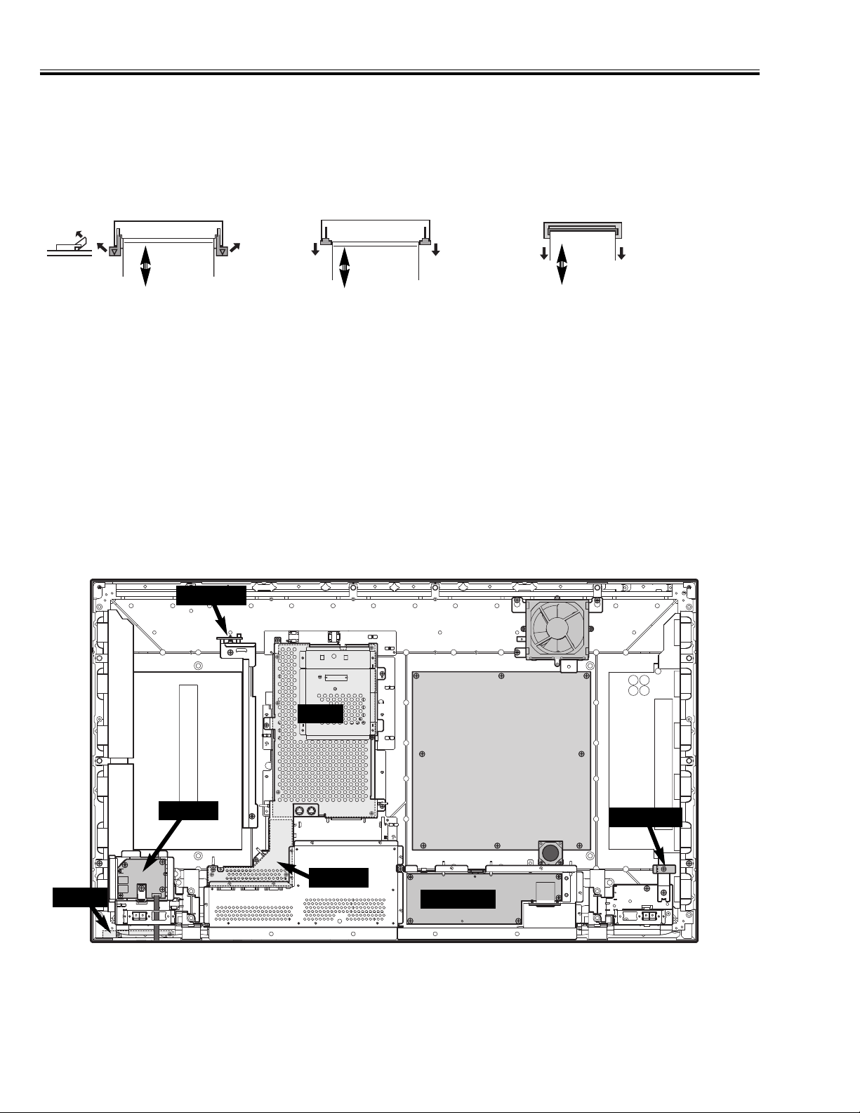
■ Flat Cable Removal
This set is used 3 kinds of connector for flat cable. For removal of cable, refer as below not to damage.
■ For Gasket
The gasket is provided to prevent exposure of interference for other radio and television receptions.
The gasket should be
replaced on previous positions after servicing.
For removal of flat cable, slide hook of
both sides.
For insert and fixing, slide hook to previous position after inserting the flat
cable.
Type A Type B Type C
For removal of flat cable, lift up hook of
both sides.
For insert and fixing, hold down hook
after inserting the flat cable.
For removal of flat cable, pull off only.
For fixing , insert into socket.
Cable
Cable
Cable
Mechanical Disassemblies
■ Notice for service of Board
In below boards, can be repaired inside parts or unit itself. Order service parts for repair.
Main
Power
Jack-A
Jack-B
Sensor-A
Sensor-B
Control
Note: Control Board and Membrane Switch are fixed at Cabinet Front.
Page 9
-9-
■ Adjustment
Before Adjustment
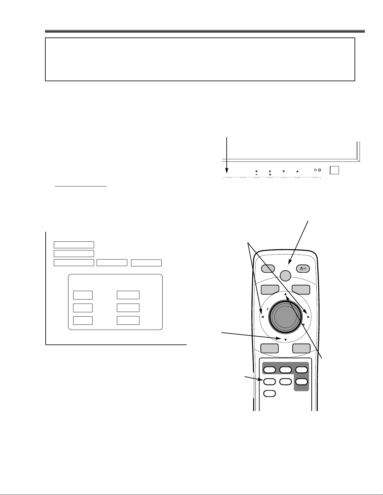
This adjustment is done to enter Service Mode by Remote
Control Unit.
■ To enter Service Mode
Quick operation is needed to enter Service Mode.
(1) Turn the monitor on.
(2) Press and hold the MENU button on the monitor.
(3) Keep item (2) and press the STATUS button and
release the both buttons.
(4) Within 2 seconds after item (3), press the MUTE
button to appear the Service Mode Display.
■ Service Mode Display
■ To return to the Normal Mode
Once turn the Monitor off by pressing “POWER” button on the monitor or remote control unit and turn it on again.
MENU Button
➡
7/ 8
Data Setting
(-) / (+)
To enter
Service Mode
STATUS
e
To select :
Adjustment
Item
d
To select :
Adjustment
Item
Sub-Image
Sub-Cont
0
PC
Main
42WV1
CAUTION
The each circuit has been made by the fine adjustment at factory. Do not attempt to adjust
the following adjustments except requiring the readjustments in servicing otherwise it may
cause loss of performance and product safety.
To enter
Service Mode
MUTE
1ah(26)
215
Model 215(WV1)
Sub 138
Temp1 27
Temp2 10
PDP Time 10h
OK
INPUTMENU
VOLUME
PICTURE
INPUT
E
M
U
L
O
V
MUTE
ON-OFF
BACK
V
O
L
U
M
E
MENU
OK
LOCAT 2-Win SIZE
STATUS
F
WIDE ON-OFF
PIP
Page 10
-10-
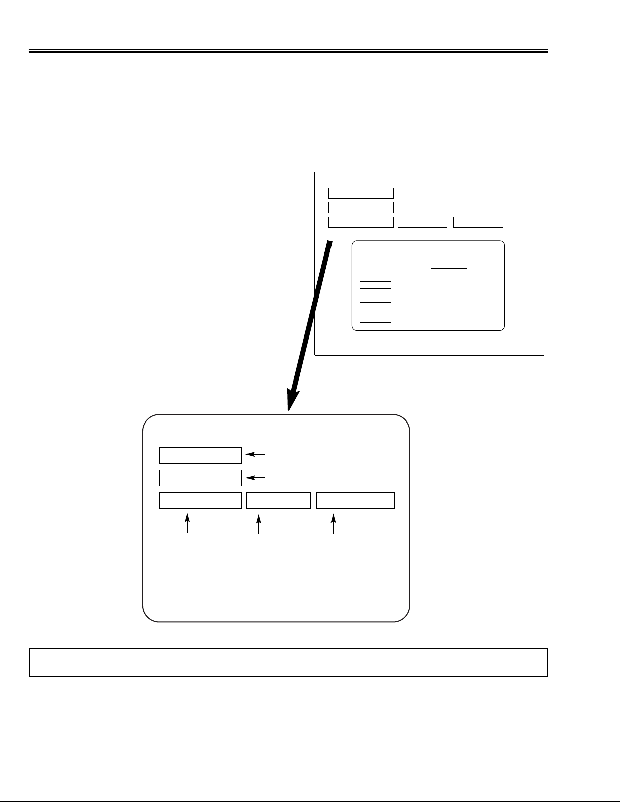
■ To adjust
The next 5 pages show Data for adjustment.
To select adjustment item, press eor dbutton on the remote control unit.
To adjust data, press 7or 8button on the remote control unit.
The all data adjusted in service mode memorizes into non-volatile memory IC.
Note: In the explanation all buttons are indicated for remote control unit without any notice.
Service Mode Display
Sub-Image
1) Select adjustment item by ebut-
ton.
Adjustment item is displayed in order. To
reverse adjustment item, press
d
button.
Selected byeordButton Adjusted by
7
or8Button.
3) To exit the Service Mode.
To exit the service mode, press POWER ON-
OFF button on the monitor or remote control
unit.
2) Adjust the data by 7or 8button.
Sub-Cont PC 1ah(26)
Adjustment Item Adjustment Data
Number
Adjustment
Sub-Image
Sub-Cont
0
PC
Main
42WV1
1ah(26)
215
Model 215(WV1)
Sub 138
Temp1
27
Temp2 23
PDP Time 10h
0
Adjustment Mode
Adjustment Name
✽ This menu is for factory data,
not used for servicing.
✽
Page 11

-11-
■ Service Adjustment Data Table
Adjustment
• All data except in gray box area is fixed. Do not change for correct operating.
• Data in gray box area is initial. Can be set according to adjustment information.
0 Sub Image PC Sub-Cont 1ah(26)
1 Sub-Bright 80h(128)
2 Sub-Color 23h(35)
3 Sub-Tint 80h(128)
4 Component Sub-Cont 1ch(28)
5 Sub-Bright 26h(38)
6 Sub-Color 1ch(28)
7 Sub-Tint 80h(128)
8 NTSC Sub-Cont 1ch(28)
9 Sub-Bright 80h(128)
10 Sub-Color 1fh(31)
11 Sub-Tint 80h(128)
12 PAL Sub-Cont 1bh(27)
13 Sub-Bright 80h(128)
14 Sub-Color 1fh(31)
15 Sub-Tint 80h(128)
16 SECAM Sub-Cont 1bh(27)
17 Sub-Bright 80h(128)
18 Sub-Color 1fh(31)
19 Sub-Tint 80h(128)
20 D PC Sub-Cont 15h(21)
21 Sub-Bright 80h(128)
22 Sub-Color 23h(35)
23 Sub-Tint 80h(128)
24 TEL TEXT Sub-Cont 1ch(28)
25 Sub-Bright 80h(128)
26 Sub-Color 20h(32)
27 Sub-Tint 80h(128)
28 HDCP Sub-Cont 15h(21)
29 Sub-Bright 80h(128)
30 Sub-Color 23h(35)
31 Sub-Tint 80h(128)
32 PC Sub-Sharp 09h(9)
33 Component D1 Sub-Sharp 15h(21)
34 Component D2 Sub-Sharp 15h(21)
35 Component D3 Sub-Sharp 15h(21)
36 Component D4 Sub-Sharp 15h(21)
37 NTSC YC Sub-Sharp 0ch(12)
38 PAL YC Sub-Sharp 0ch(12)
39 SECAM YC Sub-Sharp 0ch(12)
40 NTSC VBS Sub-Sharp 0dh(13)
41 PAL VBS Sub-Sharp 0dh(13)
42 SECAM VBS Sub-Sharp 0dh(13)
43 SCART Sub-Sharp 00h(0)
44 TEL TEXT Sub-Sharp 0ch(12)
45 Image Menu Standard AV Contrast 34h(52)
46 Bright 1fh(31)
47 Color 1fh(31)
48 Tint 00h(0)
49 Sharp 08h(8)
50 Gamma 03h(3)
51 Dynamic AV Contrast 3fh(63)
52 Bright 1fh(31)
53 Color 23h(35)
54 Tint 00h(0)
55 Sharp 08h(8)
NO. Name Mode Item Initial Data Note
Page 12

-12-
Adjustment
56 Gamma 05h(5)
57 Cinema AV Contrast 1fh(31)
58 Bright 1fh(31)
59 Color 1bh(27)
60 Tint 00h(0)
61 Sharp 08h(8)
62 Gamma 00h(0)
63 Standard PC Contrast 2fh(47)
64 Bright 1fh(31)
65 Color 1fh(31)
66 Tint 00h(0)
67 Sharp 08h(8)
68 Gamma 03h(3)
69 Graphics PC Contrast 3fh(63)
70 Bright 1fh(31)
71 Color 23h(35)
72 Tint 00h(0)
73 Sharp 0ch(12)
74 Gamma 05h(5)
75 Text PC Contrast 28h(40)
76 Bright 1fh(31)
77 Color 19h(25)
78 Tint 00h(0)
79 Sharp 07h(7)
80 Gamma 07h(7)
81 VPC3230D AV AB Low Byte 1ch(28)
82 AB High Byte 02h(2)
83 AC Low Byte 1ch(28)
84 AC High Byte 02h(2)
85 BE 06h(6)
86 PLL 02h(2)
87 AD9884 540p Phase 10h(16)
88 540p(50) Phase 10h(16)
89 525i Phase 12h(18)
90 625i Phase 12h(18)
91 525p Phase 10h(16)
92 625p Phase 10h(16)
93 1035i / 1080i Phase 10h(16)
94 1080i(50) Phase 10h(16)
95 720p Phase 16h(22)
96 720p(50) Phase 10h(16)
97 Out 525i On/Off 01h(1)
98 Out 625i On/Off 01h(1)
99 Color Balance White:VBS/YC Red 80h(128)
100 Green 80h(128)
101 Blue 80h(128)
102 Black:VBS/YC Red 00h(0)
103 Green 00h(0)
104 Blue 00h(0)
105 White:Component Red 80h(128)
106 Green 80h(128)
107 Blue 80h(128)
108 Black:Component Red 00h(0)
109 Green 00h(0)
110 Blue 00h(0)
111 White:PC Red 75h(117)
112 Green 80h(128)
113 Blue 75h(117)
114 Black:PC Red 00h(0)
115 Green 00h(0)
NO. Name Mode Item Initial Data Note
Page 13

-13-
Adjustment
116 Blue 00h(0)
117 White:DVI/HDCP Red 80h(128)
118 Green 80h(128)
119 Blue 80h(128)
120 Black:DVI/HDCP Red 00h(0)
121 Green 00h(0)
122 Blue 00h(0)
123 Color Temp AV High Red 76h(118)
124 Green 7ah(122)
125 Blue 80h(128)
126 AV Mid Red 80h(128)
127 Green 80h(128)
128 Blue 80h(128)
129 AV Low Red 80h(128)
130 Green 7eh(126)
131 Blue 73h(115)
132 PC High Red 76h(118)
133 Green 7ah(122)
134 Blue 80h(128)
135 PC Mid Red 80h(128)
136 Green 80h(128)
137 Blue 80h(128)
138 PC Low Red 80h(128)
139 Green 7eh(126)
140 Blue 73h(115)
141 Sound Device Sound AGC On/Off 00h(0)
142 Level 01h(1)
143 Sound BCSB/Bass Sub-Set 01h(1)
144 Sound BCST/Treb Sub-Set 01h(1)
145 Wide Pc Just Width +/- Flag 00h(0)
146 Data High 00h(0)
147 Data Low 00h(0)
148 Video Just Width +/- Flag 00h(0)
149 Data High 27h(39)
150 Data Low 00h(0)
151 PDP Error Diffusion On/Off SW 02h(2)
152 H Start Pos 1 Data 20h(32)
153 H Start Width 1 Data bah(186)
154 H Start Pos 2 Data 96h(150)
155 H Start Width 2 Data 40h(64)
156 Threshold PC MPD 01h(1)
157 AV MPD 01h(1)
158 50Hz / 50Hz - 100 F SW 04h(4)
159 ABL Level Hi Data 23h(35)
160 ABL Level Lo Data 19h(25)
161 H Start Width Top 1 Bit 01h(1)
162 H Start Width Top 2 Bit 01h(1)
163 Side Bar Off Border Color Type 1 Red 00h(0)
164 Green 00h(0)
165 Blue 00h(0)
166 Side Bar On Border Color Type 2 Red 40h(64)
167 Green 40h(64)
168 Blue 40h(64)
169 Over Scan 525i VBS H Start + 1fh(31)
170 V Start + 09h(9)
171 Width + 09h(9)
172 Height + 07h(7)
173 525i YC H Start + 1fh(31)
174 V Start + 09h(9)
175 Width + 09h(9)
NO. Name Mode Item Initial Data Note
Page 14

-14-
Adjustment
176 Height + 07h(7)
177 525i Component H Start + 19h(25)
178 V Start + 0fh(15)
179 Width + 07h(7)
180 Height + 05h(5)
181 525p Component H Start + 1dh(29)
182 V Start + 0ah(10)
183 Width + 07h(7)
184 Height + 05h(5)
185 625i VBS H Start + 14h(20)
186 V Start + 1fh(31)
187 Width + 0ah(10)
188 Height + 07h(7)
189 625i YC H Start + 14h(20)
190 V Start + 1fh(31)
191 Width + 0ah(10)
192 Height + 07h(7)
193 625i Component H Start + 2fh(47)
194 V Start + 14h(20)
195 Width + 08h(8)
196 Height + 06h(6)
197 625p Component H Start + 2fh(47)
198 V Start + 14h(20)
199 Width + 08h(8)
200 Height + 08h(8)
201 1080i Component H Start + 2ch(44)
202 V Start + 20h(32)
203 Width + 05h(5)
204 Height + 05h(5)
205 1080i(50) Component H Start + 2dh(45)
206 V Start + 18h(24)
207 Width + 05h(5)
208 Height + 04h(4)
209 720p Component H Start + 1dh(29)
210 V Start + 12h(18)
211 Width + 05h(5)
212 Height + 05h(5)
213 720p(50) Component H Start + 2ch(44)
214 V Start + 13h(19)
215 Width + 05h(5)
216 Height + 05h(5)
217 540p Component H Start + 2ch(44)
218 V Start + 10h(16)
219 Width + 05h(5)
220 Height + 06h(6)
221 540p(50) Component H Start + 2dh(45)
222 V Start + 0eh(14)
223 Width + 05h(5)
224 Height + 06h(6)
225 Image AGC VPC Start Value 27h(39)
226 Limit Value 3fh(63)
227 Step Size 01h(1)
228 Stop Range 08h(8)
229 AD9884 Start Value a7h(167)
230 Limit Value 6ah(106)
231 Step Size 04h(4)
232 Stop Range 08h(8)
233 Max Peak PC Peak e6h(230)
234 TV/VBS/YC d7h(215)
235 D2 - D4 Peak d7h(215)
NO. Name Mode Item Initial Data Note
Page 15

-15-
Adjustment
236 Min Ratio —- 00h(0)
237 Avail Ratio —- 0fh(15)
238 AGC On/Off Active 01h(1)
239 AGCD1 On/Off Active 01h(1)
240 Main Ver Main Ver No. d1h(209)
241 Power State Power Fail State 00h(0)
242 Power PDP Fail State 00h(0)
243 Fan Control Mode Command 01h(1)
244 Field Control Condition - 1 Field Begin 00h(0)
245 Field End 01h(1)
246 Condition - 2 Field Begin 00h(0)
247 Field End 02h(2)
248 Condition - 3 Field Begin 00h(0)
249 Field End 03h(3)
250 Condition - 4 Field Begin 00h(0)
251 Field End 04h(4)
252 Condition - 5 Field Begin 00h(0)
253 Field End 05h(5)
254 Condition - 6 Field Begin 00h(0)
255 Field End 06h(6)
256 Color Filter Control PC Red 1 1fh(31)
257 Red 2 1fh(31)
258 Green 1 1fh(31)
259 Green 2 1fh(31)
260 Blue 1 1fh(31)
261 Blue 2 1fh(31)
262 DVI Red 1 1fh(31)
263 Red 2 1fh(31)
264 Green 1 1fh(31)
265 Green 2 1fh(31)
266 Blue 1 1fh(31)
267 Blue 2 1fh(31)
268 Component Red 1 1fh(31)
269 Red 2 1fh(31)
270 Green 1 1fh(31)
271 Green 2 1fh(31)
272 Blue 1 1fh(31)
273 Blue 2 1fh(31)
274 VBS/YC Red 1 1fh(31)
275 Red 2 1fh(31)
276 Green 1 1fh(31)
277 Green 2 1fh(31)
278 Blue 1 1fh(31)
279 Blue 2 1fh(31)
NO. Name Mode Item Initial Data Note
Page 16

-16-
■ Setting the fixed data
(1) Receive the good quality signal.
(2) Enter the Service Mode
(3) Confirm fixed data to be same as data table. If it is different, change to
correct data.
(4) Return to the Normal Mode
This adjustment is controlled by the Sub CPU (IC801) thorough the IIC Data Bus Line in the chassis, and
those adjustment data are memorized into the memory IC (IC804). Therefore, SUB CPU Board or the
memory IC (IC808) is replaced, data of those will be disappeared. Readjustment should be made. Initial
data is provided in the CPU ROM ,when memory IC (IC804) is replaced with new one, CPU ROM data is
loaded into the memory. (Data list will be shown in previous 5 pages.) Initial data is provided to operating
the monitor basically. For operating the monitor quality performance, further adjustment required following
chassis electrical adjustment.
■ White Balance Adjustment
Pattern : White Pattern
Condition : Screen Size : FULL, Picture Image Level : STANDARD
Adjustment : Enter the service mode, select item No. 111 [ Red ], 112 [ Green ] or 113 [ Blue ]
(White:PC), and adjust a proper white balance.
Note : After adjustment, confirm white balance again by normal picture.
Adjustment
Page 17
-17-
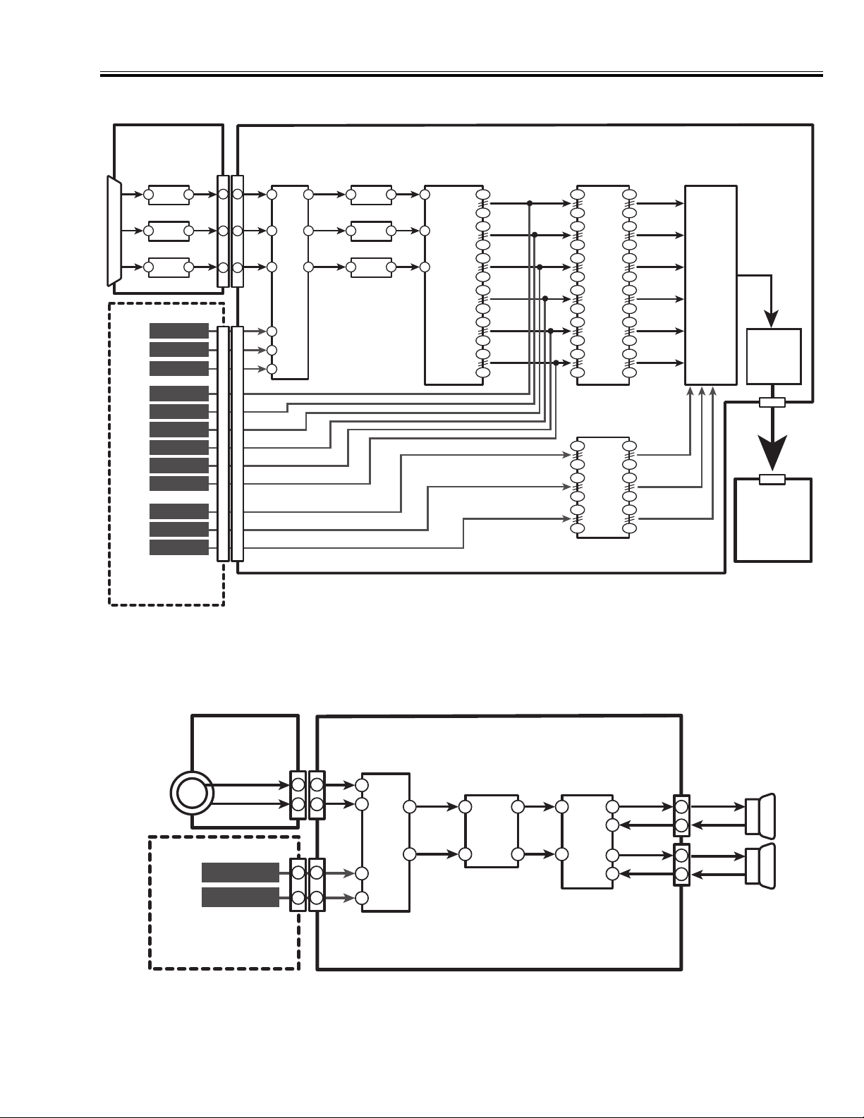
■ Circuit Block Diagram
■ Video
■ Audio
Analog PC
K1501
D-SUB
R
G
B
Input (Analog)
RGB/Component
DVI Input (Digital)
Video/S-Video
Input (Decoded)
IC1504
3
AMP
IC1506
3
AMP
IC1505
3
AMP
BNC R/CR
BNC Y/G
BNC B/CB
CRA0-7
CRZ0-7
YA0-7
YZ0-7
CBA0-7
CBZ0-7
VRA0-7
VGA0-7
VBA0-7
K1505
R
1
G
1
B
1
K8L
Interface Board
(Option)
112
105
102
95
92
85
82
75
72
65
62
55
Main
CRA0-7
CRZ0-7
YA0-7
YZ0-7
CBA0-7
CBZ0-7
VRA0-7
VGA0-7
VBA0-7
IC5001
MATRIX 1
2
9
11
18
27
34
36
43
46
53
55
62
IC5101
MATRIX 2
2
9
27
34
46
53
151
144
141
134
131
124
121
114
107
100
97
90
151
144
131
124
107
100
GRE0-7
GRO0-7
GGE0-7
GGO0-7
GBE0-7
GBO0-7
VR0-7
VG0-7
VB0-7
IC3001
Main Scaler
(Pixel Works)
IC701
LVDS
Interface
K7V
D1
PDP
Module
IC1771
Video
K8R
SW
SEL-
IC4104
R
6
6
7
G
8
10
B
R/CR
Y/G
B/CB
CRA0-7
CRZ0-7
YA0-7
YZ0-7
CBA0-7
CBZ0-7
VRA0-7
VGA0-7
VBA0-7
9
11
1
3
5
8
10
R/CR
21
19
15
SELG/Y
SELB/CB
3
AMP
IC4106
3 1
AMP
IC4107
3 1
AMP
1
R/CR
G/Y
B/CB
IC4101
A/D
Converter
7
15
22
K8L
Interface Board
Analog PC
K1504
K1505
SLOT L
SLOT R
(Option)
R
L
K8L
153015
30
3473
47
K8R
R
L
K8L
L
R
IC131
Audio
7
9
1
12
SW
13
3
SEL-R
SEL-L
IC031
Audio
Control
30
1 8
Main
23
IC101
Audio
24
27
31
28
KSP9R
R
L
AMP
R
15
L
11
KSP9L
Speaker R
(Option)
1
4
1
2
Speaker L
(Option)
Page 18
-18-
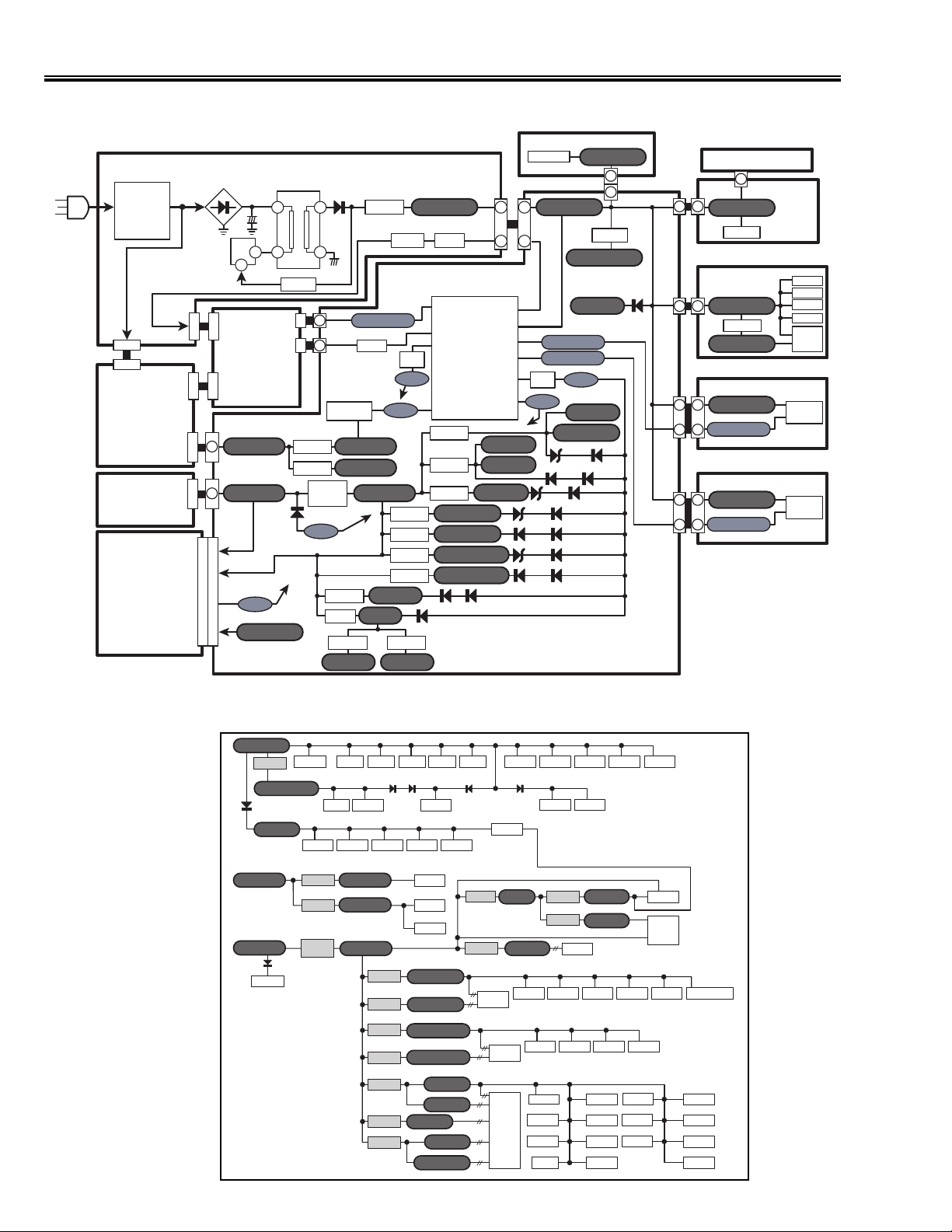
■ Power Supply Lines
■ Power Supply Lines
■ Power Source of IC (Main Board)
AC IN
POWER
Fuse
F601/2
Line Filter
LF601/2/3
POWER ON/OFF
K6A
P9
MAIN
POWER
MODULE
PDP
MODULE
OPTION
SLOT
(INTERFACE
BOARD)
K6Q
D26
AC
P6
K8L
T651
DC
5
2
Photo
Coupler
PDP
Switching
Transformer
1
3
PC651
D8
D3
11
10
1
11
D654
K8Q
RELAY
K30W
D659
IC651
Switching
Regulator
SS34
MODULE
Audio AMP
IC1602
IC1603
IC1604
PF-2
25,26,30
Q601
IC4109
L4111
IC4102
-5V_AD1
K16P
1
27V_Audio 12V_Audio
K16D
1
13V_Power 5V_Digital
D603
K8L
93, 137
6, 50, 94, 138
42
PF-4
5, 49
5V_Standby
IC1652
PANEL_FAIL
6
IC751
PDP
ON/OFF
IC101
19
9V_Analog
3.3V_AD
5V_AD
4
5
Q803
Q804
PF-4
PF-3
IC5009
IC5008
IC5107
IC5106
D4101
IC4108
-5V_AD2
5V_Standby
Q651RL651
IC801
Sub CPU
Panel
78
Fail
86
PDP GO
85
Power
Fail 4
Power
84
Fail 3
IC8071
IC8073
IC8072
2.5V_Matrix
3.3V_Matrix
2.5V_Matrix2
3.3V_Matrix2
D4102 D4103
K6C
1
8
Power
ON/OFF
VCC
T-Sensor-1
T-Sensor-2
Power
Fail 1
Power
Fail 2
3.3V_AP
3.3V_PIX
2.5V_PIX
CONTROL
A1902A
RC Pre-AMP
1
5V_Standby
K16C
8
49
16, 62, 99
92
93
82
Q801
Q802
83
PF-2
D5004
D5001
D5102
D5101
MAIN
3
3.3V_Standby
5V_SYNC
T-SENSOR-1
T-SENSOR-2
PF-1
1.5V_PIX
1.5V_PIX_P
D8072
D8076
D8071
D5002
D5003
D5104
D5103
5V_Standby
3
K19J
3
K18J
IC1651
D8073
D8074
D8077
D1711
K8F
K8R
K8N
K8M
MEMBRANE SW
K11F
44
5V_Standby
IC1101
JACK-A
K1015
18
18
5V_Standby
IC1509
-5V_D-SUB
K18N
4
4
5V_Standby
2
2
T-SENSOR-1
K18M
5
5
5V_Standby
2
2
T-SENSOR-2
5
K1104
5
JACK-B
16
8
8
16
5
2
SENSOR-A
1
IC1891
2
Temperature
Sensor
SENSOR-B
1
IC1881
2
Temperature
Sensor
IC1501
IC1502
IC1510
IC1503
IC1504
IC1505
IC1506
5V_Standby
IC1651
3.3V_Standby
D1711
5V_SYNC
27V_Audio 12V_Audio
13V_Power
8
IC1851
FAN Control
16, 62 99
IC801
Sub CPU
Reg
IC171213IC17131IC1714
Sync SEP Sync SW Sync SEP
IC1602
Reg
IC1603
Reg
Q601
IC1604
Reg
D1851
IC753
IC802
20
1
IC803
Reset
5
IC3104
9V_Analog
5V_Digital
IC5008
IC5009
IC5106
IC5107
IC8073
IC8072
IC8071
5
8
IC80616IC8075IC8402
IC804
EEPROM
IC1881
IC17168IC1717
20, 26,
IC101
30
Audio AMP
16
IC031
Audio Control
16
IC131
Audio SW
3.3V_Matrix
2.5V_Matrix
3.3V_Matrix2
2.5V_Matrix2
3.3V_PIX
3.3V_AP
2.5V_PIX
1.5V_PIX
1.5V_PIX_P
1
D1882
IC1711
5
8
L4111
5V_AD
IC4109
Reg
IC5001
Matrix_1
IC5101
Matrix_2
IC3001
Pixel Works
D1884 D1883 D1101
16
Reg
Reg
Reg
Reg
Reg
Reg
Reg
16
IC842114IC1941
IC176116IC1771
Sync SW Video SW
2
3.3V_AD
IC50025IC50031IC50048IC500614IC500714IC8101/2/3
5
IC5104
1,9,26,34
IC701
LVDS
IC8001
I/O
IC8422
IC752
IC4108
Reg
IC4102
Reg
IC4101
AD Converter
Reset
IC51081IC5102
Reset
16
73
4,16
14
5
14
2
8
IC18821IC751
20
-5V_AD2
-5V_AD1
14
IC3151
IC3152
IC3153
IC3154
IC5103
IC3101
IC3102
IC3103
Reset
2
2
8
14
14
8
IC4107
IC4104
IC4106
20
8
1
33,11
37
IC3141
Flash ROM
IC3142
20
IC3002
20
IC3003
7,18,31,42
SRAM
Page 19
-19-
■ Power Fail Circuit
Sub CPU (IC801) is programmed that the set goes to standby mode when there is circuit fail
as below. (Refer to "Power Supply Lines: P18)
1. Power Fail 1 : Detected the low voltage fail in Main board. (From 1.5V to 5V)
2. Power Fail 2 : Detected the High voltage fail in Main board. (13V)
3. Power Fail 3 : Detected the fail of Audio AMP IC (IC101).
4. Power Fail 4 : Detected the voltage fail of Interface Board (Option).
5. Temperature Fail : Detected the fail of Temperature Sensor IC (IC1881/1891).
6. Panel Fail (ALARM) : Detected the fail of PDP Module.
Note: In case of Panel Fail (ALARM), the set does not go to standby mode. (Only "PDP_GO" line is off.)
IC801
P FAIL 1
P FAIL 2
P FAIL 3
P FAIL 4
TEM. FAIL 1
TEM. FAIL 2
PANEL FAIL
POWER
ON/OFF
82
83
84
85
92
93
79
49
Low Voltage (1.5V - 5V) Fail Detect
(High: Normal, Low: Fail)
High Voltage (13V) Fail Detect
(High: Normal, Low: Fail)
Sound AMP. Fail Detect (To IC101 19 )
(Low: Normal, High: Fail)
(Option) Interface Board Voltage Fail Detect
(High: Normal, Low: Fail)
Temperature Fail Detect (To IC1891 2 )
Temperature Fail Detect (To IC1881 2 )
Panel Module Fail Detect
(High: Normal, Low: Fail)
Standby ON/OFF
(High: ON, Low: OFF)
PDP GO
86
PDP Module ON/OFF
(High: ON, Low: OFF)
Page 20

-20-
Power Fail Circuit
When operating the Power Fail Circuit, On-Screen-Display message or LED flashing time is
shown as below.
On-Screen-Display Message
1. TEMPERATURE FAIL
When the internal temperature exceeds normal ( approximately more than 80 degrees ), below message is
displayed for 10 seconds and the Plasma monitor will be turned off automatically.
LED Flashing
1. PANEL & TEMPERATURE FAIL: The color of LED is ‘RED’.
2. POWER FAIL 1& 2: The color of LED is ‘GREEN’.
3. POWER FAIL 3& 4: The color of LED is ‘YELLOW’.
Warning!
Internal temperature is too high.
Times of flashing Fail Name
1 Power Fail 1
2 Power Fail 2
3 Power Fail 1 & 2
Note:
1. In case of overlapped fail, 1 to 3 is repeated in turn.
2. If power fail is detected 3 times in 15 minutes, the monitor will stop operating.
Note:If pull off the AC cord, the information of these fails will be disappeared.
Times of flashing Fail Name
1 Panel Fail
2 Temperature Fail
3 Panel & Temperature Fail
Times of flashing Fail Name
1 Power Fail 3
2 Power Fail 4
3 Power Fail 3 & 4
Page 21

-21-
Power Fail Circuit
When finishing the repair or stopping Power Fail, can be checked the history of the past fails.
To see the history
1. Enter the service mode. (Refer to "Adjustment" P9 - P10.)
2. Check the Item No.241 or No.242 of Service Adjustment Data Table. (Refer to P15.)
1. History of Power Fail (Item No. 241)
Fail Name Data
No Fail 00h(0)
Power Fail 1 01h(1)
Power Fail 2 02h(2)
Power Fail 3 04h(4)
Power Fail 4 08h(8)
Panel Fail (ALARM) 10h(16)
Temperature Fail 20h(32)
2. History of Panel Fail (Item No. 242)
Fail Name Data
No Panel Fail 00h(0)
Voltage Fail (5V) 01h(1)
Voltage Fail (3V) 02h(2)
Panel Driver Fail 04h(4)
Note: If counted the overlapped fail, the sum of
each data is displayed.
For example:
Power Fail 2 & Panel Fail (ALARM)
02h + 10h = 12h(18)
Note: If counted the overlapped fail, the sum of
each data is displayed.
For example:
Voltage Fail (5V) & Panel Driver Fail
01h + 04h = 05h(5)
Attention: After finishing the service, their data should be reset to "00h(0)".
Page 22

-22-
■ Troubleshooting
No Power
Refer to Schematic Diagram or Power Supply Line, find out the part of trouble.
Before opening Cabinet Back, check the AC cord and power source.
Is LED flashed?
No
Ye s
Is
the voltage of
all lines in Power Unit
supplied?
Ye s
(or the voltage of some
lines is not supplied.)
After few seconds,
the set is switched off.
Check 'Fail' Circuit to refer service
manual 'Power Fail Circuit'.
No
(All 0V)
Is
fuse (F601/602)
in Power Board
broken?
No
Ye s
Check D659 or IC651 in
Power Board.
Check VA601 in Power
Board.
Main Power Module is
broken.
Check '5V_Standby' line
from Power Board to Main
Board.
Check PTH651 in Power
Board.
Check arround Sub CPU
(IC801) in Main Board.
Main Power Module is
broken.
Page 23

-23-
● System Control (Sub-CPU : IC801)
■ Control Port Functions
1 P96/ANEX1/SOUT4 RTC_DATAOUT O For real time clock
2 P95/ANEX0/CLK4 RTC_CLK O For real time clock
3 P94/DA1/TB4IN FAN-CTRL1 O Fan control 1 D/A
4 P93/DA0/TB3IN FAN-CTRL2 O Fan control 2 D/A
5 P92/TB2IN/SOUT3 Not used (Output: Low)
6 P91/TB1IN/SIN3 HS_DET I (Analog)PC-HSYNC IN DPMS input
7 P90/TB0IN/CLK3 Not used (Output: Low)
8 BYTE
9 CNVss CNVSS For writing
10 P87/XCIN Not used (Output: Low)
11 P86/XCOUT Not used (Output: Low)
12 RESET CPURST IC reset
13 XOUT
14 VSS
15 XIN
16 VCC
17 P85/NMI
18 P84/INT2 RC I RC input RC input
19 P83/INT1 Not used (Output: Low)
20 P82/INT0 VS_DET I (Analog)PC-VSYNC IN DPMS input
21 P81/TA4IN/U Not used (Output: Low)
22 P80/TA4OUT/U Not used (Output: Low)
23 P77/TA3IN Not used (Output: Low)
24 P76/TA3OUT Not used (Output: Low)
25 P75/TA2IN/W Not used (Output: Low)
26 P74/TA2OUT/W Not used (Output: Low)
27 P73/CTS2/RTS2/TA1IN/V Not used (Output: Low)
28 P72/CLK2/TA1OUT/V Not used (Output: Low)
29 P71/RxD2/SCL/TA0IN/TB5IN RXD2 I UART for option board Not used (Output: Low)
30 P70/TXD2/SDA/TA0OUT TXD2 O UART for option board Not used (Output: Low)
31 P67/TXD1 UARTTX O UART for PIX TX
32 P66/RxD1 UARTRX I UART for PIX RX
33 P65/CLK1 SCLCK I For writing Output: Low
34 P64/CTS1/RTS1/CLKS1 BUSY I For writing Output: Low
35 P63/TXD0 RS232C_RX O Control for RS232C RX
36 P62/RxD0 RS232C_TX I Control for RS233C TX
37 P61/CLK0 Not used (Output: Low)
38 P60/CTS0/RTS0 Not used (Output: Low)
39 P57/RDY/CLKOUT Not used (Output: Low)
40 P56/ALE Not used (Output: Low)
41 P55/HOLD EPM For writing Input
42 P54/HLDA DVI HOT DVI HOT High:Permisson
43 P53/BCLK Not used (Output: Low)
44 P52/RD Not used (Output: Low)
45 P51/WRH/BHE Not used (Output: Low)
46 P50/WRL/WR CE For writing Not used (Output: Low)
47 P47/CS3 Not used (Output: Low)
48 P46/CS2 RTC_CE For real time clock High:Communication
49 P45/CS1 STB O Power ON/OFF High:ON, Low:OFF
50 P44/CS0 AMP-MUTE1 O Low:Mute
51 P43/A19 RS232C_A O Mode SW for RS232C 51Pin /52Pin:
H/H:Multi-monitor,
52 P42/A18 RS232C_B O Mode SW for RS233C H/L:Inter-communication,
L/H:Through, L/L:Not used
53 P41/A17 Not used (Output: Low)
54 P40/A16 Not used (Output: Low)
55 P37/A15 SCL EEPROM
56 P36/A14 SDA EEPROM
57 P35/A13 Not used (Output: Low)
58 P34/A12 SCDT_ST1 I Low:No signal
59 P33/A11 Not used (Output: Low)
60 P32/A10 L-RED O High:ON, LowOFF
Pin NO. Pin Name Signal Name I/O Note Data
Page 24

-24-
Control Port Functions
61 P31/A9 L-GREEN O High:ON, LowOFF
62 VCC
63 P30/A8(/-/D7) Not used (Output: Low)
64 Vss
65 P27/A7(/D7/D6) Not used (Output: Low)
66 P26/A6(/D6/D5) Not used (Output: Low)
67 P25/A5(/D5/D4) Not used (Output: Low)
68 P24/A4(/D4/D3) Input
69 P23/A3(/D3/D2) Input
70 P22/A2(/D2/D1) Input
71 P21/A1(/D1/D0) Not used (Output: Low)
72 P20/A0(/D0/-) RESET_SW I Externai reset SW (Input) Low:Reset
73 P17/D15/INT5 FCOM O For real time clock Low:Fixed
74 P16/D14/INT4 AIRQ I For real time clock Not used (Input)
75 P15/D13/INT3 YIRQ I For real time clock
76 P14/D12 Not used (Output: Low)
77 P13/D11 FAN-LOCK1 I Fan Lock Input High:Normal, Low:Locked
78 P12/D10 PANEL-LED I Panel LED (Fail Detection)
79 P11/D9 ALARM I Panel Fail High:Normal, Low:Fail
80 P10/D8 PW_RST O PIX reset (Output) High:Reset
81 P07/D7 LINE OFF I Power OFF Detection Low:AC OFF
82 P06/D6 P-FAIL1 I 1.5V,2.5V,3.3V,5V High:Normal, Low:Fail
83 P05/D5 P-FAIL2 I 9V,12,13V High:Normal, Low:Fail
84 P04/D4 P-FAIL3 I For Audio AMP IC High:Fail, Low:Normal
85 P03/D3 P-FAIL4 I For Option Board (Slot) High:Normal, Low:Fail
86 P02/D2 PDPGO_5 O Panel ON/OFF High:ON, Low:OFF
87 P01/D1 PWRSW I Power SW
88 P00/D0 FAN-LOCK2 I Fan Lock Input High:Normal, Low:Locked
89 P107/AN7/KI3 Not used (Output: Low)
90 P106/AN6/KI2 Not used (Output: Low)
91 P105/AN5/KI1 Not used (Output: Low)
92 P104/AN4/KI0 T-SENSOR1 I Temp-Sensor (Analog input) A/D
93 P103/AN3 T-SENSOR2 I Temp-Sensor (Analog input) A/D
94 P102/AN2 Not used (Output: Low)
95 P101/AN1 KEY-IN I Key Input A/D
96 AVSS Not used (Output: Low)
97 P100/AN0 Not used (Output: Low)
98 VREF Not used (Output: Low)
99 AVcc Not used (Output: Low)
100 P97/ADTRG/SIN4 RTC_DATA I For real time clock
Pin NO. Pin Name Signal Name I/O Note Data
Page 25

-25-
■ Pin Description of Diode, Transistor and IC
● Diode
K
A
● Transistor/FET
E
C
B
C
E
C
B
E
B
C
● IC
K
A
K
A
K
K
K: Cathode
A: Anode
AA
C
E
E
B
C
B
B1
C1
CBE
C2
B2
E
C
BE
B1
C1
E
C2
Vdd
2
KK
C1
C2
B1 B2
E
B2
C2
E2 C1
B1
B2
A
B1
E1
B2
(GND)
2
Index
E1
C1
C2
E2
A
C: Collector
B: Base
E: Emitter
D: Drain
G: Gate
S: Source
S
G
D
S
D
G
3
1
3
2
Index
Index
N
1
Index
1
Index
3
2
Index
1
3
N
GND
(IN)
Index
3
1
(OUT)
4
5
6
21
5
4
3
2
1
Index
N
1
RESET
1
2
N
1
2
1
2
1
3
1
N
N
Index
Index
N
1
N
1
Page 26

-26-
■ Parts List
MECHANICAL PARTS
1 610 305 4827 ASSY,CABINET BACK-J3TF
2 610 305 2373 CABINET FRONT-J3TF
(PDP-42WV1 / PDP-42WV1A)
610 308 6705 CABINET FRONT-J3TG
(PDP-42WV1S / PDP-42WV1AS)
3 610 306 3508 COVER-J3TF
4 610 308 6378 COVER SHEET-J3TF
5 610 305 4353 HANDLE L-J3TF
6 610 305 4360 HANDLE R-J3TF
7 610 305 7422 DEC SHEET-J3TF
8 610 305 7439 DEC SHEET R-J3TF
9 610 305 7446 DEC SHEET AC IN-J3TF
10 610 305 2427 DEC INLAY-J3TF
11 610 305 2410 DEC IND-J3TF
ACCESSORY
645 059 8050 ASSY,REMOCON JXMZA
610 306 2532 RC-BATTERY LID-CXPH
645 051 2322 RC CABLE,FXAF
645 023 4958 CORE,CLAMP
645 054 1162 CORD,POWER-3.0MK (US)
645 054 1155 CORD,POWER-3.0MK (EU, ASIA)
645 054 1148 CORD,POWER-3.138MK (UK)
OWNERS MANUAL
610 305 7934 OWNERS MANUAL-J3TF (English)
610 305 7941 OWNERS MANUAL-J3TF-D (Germany)
610 305 7958 OWNERS MANUAL-J3TF-F (French)
610 305 7965 OWNERS MANUAL-J3TF-I (Italian)
610 305 7972 OWNERS MANUAL-J3TF-E (Spanish)
!!!
Fig. No. Part No. Description Part No. Description
Button (Membrane SW)
See Electric Parts.
1
2
3
4
7
8
9
6
5
11
10
Page 27

-27-
Electrical Parts List
Product safety should be considered when a component replacement is made in any area of a PDP monior.
Components indicated by a mark in this parts list and the circuit diagram show components whose value have
special significance to product safety. It is particularly recommended that only parts specified on the following parts
list be used for components replacement pointed out by the mark.
!
● Read Description in the parts list
Read description in the Capacitor and Resistor as follows:
CAPACITOR
CERAMIC 100P K 50V
Rated Voltage
Tolerance Symbols:
Less than 10pF
A : Not specified B : ±0.1pF C : ±0.25pF
D : ±0.5pF E : +0 -1pF F : ±1PF
G : ±2pF H : +0.1 -0pF L : +0 -0.1pF
R : ±0.25 -0pF S : +0-0.25pF
More than 10pF
A : Not specified B : ±0.1% C : ±0.25%
D : ±0.5% F : ±1% G : ±2%
H : ±3% J : ±5% K : ±10%
L : ±15% M : ±20% N : ±30%
P : +100-0% Q : +30-10% T : +50-10%
U : +75-10% V : +20-10% W : +100-10%
X : +40-20% Y : +150-10%Z : +80-20%
Rated value: P=pico farad, U=micro farad
Material:
CERAMIC...........Ceramic
MT-PAPER.........Metallized Paper
POLYESTER......Polyester
MT-POLYEST.....Metallized Polyester
POLYPRO..........Polypropylene
MT-POLYPRO....Metallized Polypropylene
COMPO FILM.....Composite film
MT-COMPO........Metallized Composite
STYRENE...........Styrene
TA-SOLID...........Tantalum Oxide Solid Electrolytic
AL-SOLID...........Aluminium Solid Electrolytic
ELECT................Aluminum Foil Electrolytic
NP-ELECT..........Non-polarised Electrolytic
OS-SOLID..........Aluminium Solid with Organic Semiconductive Electrolytic
POS-SOLID........Polymerized Organic Semiconductive
DL-ELECT..........Double Layered Electrolytic
PPS-FILM...........Polyphenylene Sulfide Film
MT-PPS-FILM.....Metalized Polyphenylene Sulfide Film
MT-PEN-FILM.....Metalized Polyethylenenaphthalate Film
CAPACITOR.......Other
RESISTOR
CARBON 4.7K J A 1/4W
Performance Symbols:
A: General B: Non flammable Z: Low noise
Other: Temperature coefficient
T: ±10ppm/°C U: ±25ppm/°C C: ±50ppm/°C
D: ±100ppm/°C E: ±200ppm/°C F: ±250ppm/°C
G: ±350ppm/°C H: ±1000ppm/°C±10%W: ±1200ppm/°C±10%
Y: ±1400ppm/°C±10%J: ±2000ppm/°C±10% K: ±2400ppm/°C±10%
L: ±2700ppm/°C±10%M: ±3000ppm/°C±10%N: ±3300ppm/°C±10%
P: ±3600ppm/°C±10%Q: ±3900ppm/°C±10%R: ±4200ppm/°C±10%
S: ±4300ppm/°C±10%V: ±4500ppm/°C±10% X: ±8000ppm/°C±10%
Tolerance Symbols:
A: ±0.05% B: ±0.1% C:±0.25% D: ±0.5%
F: ±1% G: ±2% J:±5% K: ±10%
M: ±20% P: +5-15%Z: 0 ohm
Rated value, ohms:
Material:
CARBON...........Carbon
MT-FILM............Metal Film
OXIDE-MT.........Oxide Metal Film
SOLID................Composition
MT-GLAZE.........Metal Glaze
WIRE WOUND...Wire Wound
CERAMIC RES..Ceramic
FUSIBLE RES....Fusible
RESISTOR ........Other
K: 1,000, M: 1,000,000
Rated Wattage
Page 28

Electrical Parts List
-28-
MISCELLANEOUS
EL901 645 059 6131 PDP MODULE
(For PDP-42WV1 / PDP-42WV1S)
EL901 645 059 5424 PDP MODULE
(For PDP-42WV1A / PDP-42WV1AS)
EL902 645 059 6117 OPTICAL FILTER
FN901 645 057 8649 MOTOR,FAN DC 1.8W
FN903 645 062 2458 MOTOR,FAN DC 0.744W
M901 610 305 6487 BUTTON-42-J3TF (MENBRANE SW)
(For PDP-42WV1 / PDP-42WV1A)
M901 610 308 1120 BUTTON-42-J3TA (MENBRANE SW)
(For PDP-42WV1S / PDP-42WV1AS)
SPL 645 061 8086 SPEAKER TERMINAL,BOARD
SPR 645 061 8086 SPEAKER TERMINAL,BOARD
W7V-D1 610 305 9235 CORD 21P 1.25MM(LVDS CABLE)
610 305 0775 ASSY,PWB,MAIN-J3TF 1AA0B10N04000
TRANSISTOR
Q101 405 014 4509 TR 2SC2412K T146 R
405 014 4608 TR 2SC2412K T146 S
405 015 8704 TR 2SC2812-L6-TB
405 015 8902 TR 2SC2812-L7-TB
405 163 1602 TR 2SC2812N-L6-TB0
405 163 1701 TR 2SC2812N-L7-TB0
405 173 9803 TR 2SC3928A1R
405 173 9902 TR 2SC3928A1S
Q131 405 014 4509 TR 2SC2412K T146 R
405 014 4608 TR 2SC2412K T146 S
405 015 8704 TR 2SC2812-L6-TB
405 015 8902 TR 2SC2812-L7-TB
405 163 1602 TR 2SC2812N-L6-TB0
405 163 1701 TR 2SC2812N-L7-TB0
405 173 9803 TR 2SC3928A1R
405 173 9902 TR 2SC3928A1S
Q132 405 014 4509 TR 2SC2412K T146 R
405 014 4608 TR 2SC2412K T146 S
405 015 8704 TR 2SC2812-L6-TB
405 015 8902 TR 2SC2812-L7-TB
405 163 1602 TR 2SC2812N-L6-TB0
405 163 1701 TR 2SC2812N-L7-TB0
405 173 9803 TR 2SC3928A1R
405 173 9902 TR 2SC3928A1S
Q133 405 014 4509 TR 2SC2412K T146 R
405 014 4608 TR 2SC2412K T146 S
405 015 8704 TR 2SC2812-L6-TB
405 015 8902 TR 2SC2812-L7-TB
405 163 1602 TR 2SC2812N-L6-TB0
405 163 1701 TR 2SC2812N-L7-TB0
405 173 9803 TR 2SC3928A1R
405 173 9902 TR 2SC3928A1S
Q134 405 014 4509 TR 2SC2412K T146 R
405 014 4608 TR 2SC2412K T146 S
405 015 8704 TR 2SC2812-L6-TB
405 015 8902 TR 2SC2812-L7-TB
405 163 1602 TR 2SC2812N-L6-TB0
405 163 1701 TR 2SC2812N-L7-TB0
405 173 9803 TR 2SC3928A1R
405 173 9902 TR 2SC3928A1S
Q1601 405 151 2000 TR FSS134-TL
Q1711 405 134 5905 TR 2SA1037AK-T146-R
405 147 2205 TR 2SA1037AK-S-T146
405 002 0308 TR 2SA1037K T146 R
405 002 0407 TR 2SA1037K T146 S
405 002 6706 TR 2SA1179-M6-TB
405 002 6904 TR 2SA1179-M7-TB
405 163 1503 TR 2SA1179N-M6-TB
405 163 2708 TR 2SA1179N-M7-TB
405 173 9605 TR 2SA1235A1E
405 173 9704 TR 2SA1235A1F
Q1712 405 014 4509 TR 2SC2412K T146 R
405 014 4608 TR 2SC2412K T146 S
405 015 8704 TR 2SC2812-L6-TB
405 015 8902 TR 2SC2812-L7-TB
405 163 1602 TR 2SC2812N-L6-TB0
405 163 1701 TR 2SC2812N-L7-TB0
405 173 9803 TR 2SC3928A1R
405 173 9902 TR 2SC3928A1S
Q1713 405 014 4509 TR 2SC2412K T146 R
405 014 4608 TR 2SC2412K T146 S
405 015 8704 TR 2SC2812-L6-TB
405 015 8902 TR 2SC2812-L7-TB
405 163 1602 TR 2SC2812N-L6-TB0
405 163 1701 TR 2SC2812N-L7-TB0
405 173 9803 TR 2SC3928A1R
405 173 9902 TR 2SC3928A1S
Q1714 405 014 4509 TR 2SC2412K T146 R
405 014 4608 TR 2SC2412K T146 S
405 015 8704 TR 2SC2812-L6-TB
405 015 8902 TR 2SC2812-L7-TB
405 163 1602 TR 2SC2812N-L6-TB0
405 163 1701 TR 2SC2812N-L7-TB0
405 173 9803 TR 2SC3928A1R
405 173 9902 TR 2SC3928A1S
Q1715 405 014 4509 TR 2SC2412K T146 R
405 014 4608 TR 2SC2412K T146 S
405 015 8704 TR 2SC2812-L6-TB
405 015 8902 TR 2SC2812-L7-TB
405 163 1602 TR 2SC2812N-L6-TB0
405 163 1701 TR 2SC2812N-L7-TB0
405 173 9803 TR 2SC3928A1R
405 173 9902 TR 2SC3928A1S
Q1716 405 014 4509 TR 2SC2412K T146 R
405 014 4608 TR 2SC2412K T146 S
405 015 8704 TR 2SC2812-L6-TB
405 015 8902 TR 2SC2812-L7-TB
405 163 1602 TR 2SC2812N-L6-TB0
405 163 1701 TR 2SC2812N-L7-TB0
405 173 9803 TR 2SC3928A1R
405 173 9902 TR 2SC3928A1S
Q1717 405 014 4509 TR 2SC2412K T146 R
405 014 4608 TR 2SC2412K T146 S
405 015 8704 TR 2SC2812-L6-TB
405 015 8902 TR 2SC2812-L7-TB
405 163 1602 TR 2SC2812N-L6-TB0
405 163 1701 TR 2SC2812N-L7-TB0
405 173 9803 TR 2SC3928A1R
405 173 9902 TR 2SC3928A1S
Q1771 405 014 4509 TR 2SC2412K T146 R
405 014 4608 TR 2SC2412K T146 S
405 015 8704 TR 2SC2812-L6-TB
405 015 8902 TR 2SC2812-L7-TB
405 163 1602 TR 2SC2812N-L6-TB0
405 163 1701 TR 2SC2812N-L7-TB0
405 173 9803 TR 2SC3928A1R
405 173 9902 TR 2SC3928A1S
Q1772 405 014 4509 TR 2SC2412K T146 R
405 014 4608 TR 2SC2412K T146 S
405 015 8704 TR 2SC2812-L6-TB
405 015 8902 TR 2SC2812-L7-TB
405 163 1602 TR 2SC2812N-L6-TB0
405 163 1701 TR 2SC2812N-L7-TB0
405 173 9803 TR 2SC3928A1R
405 173 9902 TR 2SC3928A1S
Q1773 405 014 4509 TR 2SC2412K T146 R
405 014 4608 TR 2SC2412K T146 S
405 015 8704 TR 2SC2812-L6-TB
405 015 8902 TR 2SC2812-L7-TB
405 163 1602 TR 2SC2812N-L6-TB0
405 163 1701 TR 2SC2812N-L7-TB0
405 173 9803 TR 2SC3928A1R
405 173 9902 TR 2SC3928A1S
Q1774 405 014 4509 TR 2SC2412K T146 R
405 014 4608 TR 2SC2412K T146 S
!
!
!
!
Key No. Part No. Description Key No. Part No. Description
Page 29

-29-
Electrical Parts List
405 015 8704 TR 2SC2812-L6-TB
405 015 8902 TR 2SC2812-L7-TB
405 163 1602 TR 2SC2812N-L6-TB0
405 163 1701 TR 2SC2812N-L7-TB0
405 173 9803 TR 2SC3928A1R
405 173 9902 TR 2SC3928A1S
Q1851 405 148 2907 TR 2SC5103 TL P
405 148 3003 TR 2SC5103 TL Q
Q1853 405 148 2907 TR 2SC5103 TL P
405 148 3003 TR 2SC5103 TL Q
Q1854 405 014 4509 TR 2SC2412K T146 R
405 014 4608 TR 2SC2412K T146 S
405 015 8704 TR 2SC2812-L6-TB
405 015 8902 TR 2SC2812-L7-TB
405 163 1602 TR 2SC2812N-L6-TB0
405 163 1701 TR 2SC2812N-L7-TB0
405 173 9803 TR 2SC3928A1R
405 173 9902 TR 2SC3928A1S
Q1855 405 014 4509 TR 2SC2412K T146 R
405 014 4608 TR 2SC2412K T146 S
405 015 8704 TR 2SC2812-L6-TB
405 015 8902 TR 2SC2812-L7-TB
405 163 1602 TR 2SC2812N-L6-TB0
405 163 1701 TR 2SC2812N-L7-TB0
405 173 9803 TR 2SC3928A1R
405 173 9902 TR 2SC3928A1S
Q1931 405 014 4509 TR 2SC2412K T146 R
405 014 4608 TR 2SC2412K T146 S
405 015 8704 TR 2SC2812-L6-TB
405 015 8902 TR 2SC2812-L7-TB
405 163 1602 TR 2SC2812N-L6-TB0
405 163 1701 TR 2SC2812N-L7-TB0
405 173 9803 TR 2SC3928A1R
405 173 9902 TR 2SC3928A1S
Q1932 405 014 4509 TR 2SC2412K T146 R
405 014 4608 TR 2SC2412K T146 S
405 015 8704 TR 2SC2812-L6-TB
405 015 8902 TR 2SC2812-L7-TB
405 163 1602 TR 2SC2812N-L6-TB0
405 163 1701 TR 2SC2812N-L7-TB0
405 173 9803 TR 2SC3928A1R
405 173 9902 TR 2SC3928A1S
Q3101 405 045 8705 TR 2SK536-TB
Q3102 405 045 8705 TR 2SK536-TB
Q4101 405 079 1505 TR 2SC4269-4-TB
Q4102 405 079 1505 TR 2SC4269-4-TB
Q4103 405 079 1505 TR 2SC4269-4-TB
Q751 405 045 8705 TR 2SK536-TB
Q752 405 045 8705 TR 2SK536-TB
Q753 405 045 8705 TR 2SK536-TB
Q801 405 014 4509 TR 2SC2412K T146 R
405 014 4608 TR 2SC2412K T146 S
405 015 8704 TR 2SC2812-L6-TB
405 015 8902 TR 2SC2812-L7-TB
405 163 1602 TR 2SC2812N-L6-TB0
405 163 1701 TR 2SC2812N-L7-TB0
405 173 9803 TR 2SC3928A1R
405 173 9902 TR 2SC3928A1S
Q802 405 134 5905 TR 2SA1037AK-T146-R
405 147 2205 TR 2SA1037AK-S-T146
405 002 0308 TR 2SA1037K T146 R
405 002 0407 TR 2SA1037K T146 S
405 002 6706 TR 2SA1179-M6-TB
405 002 6904 TR 2SA1179-M7-TB
405 163 1503 TR 2SA1179N-M6-TB
405 163 2708 TR 2SA1179N-M7-TB
405 173 9605 TR 2SA1235A1E
405 173 9704 TR 2SA1235A1F
Q803 405 014 4509 TR 2SC2412K T146 R
405 014 4608 TR 2SC2412K T146 S
405 015 8704 TR 2SC2812-L6-TB
405 015 8902 TR 2SC2812-L7-TB
405 163 1602 TR 2SC2812N-L6-TB0
405 163 1701 TR 2SC2812N-L7-TB0
405 173 9803 TR 2SC3928A1R
405 173 9902 TR 2SC3928A1S
Q804 405 134 5905 TR 2SA1037AK-T146-R
405 147 2205 TR 2SA1037AK-S-T146
405 002 0308 TR 2SA1037K T146 R
405 002 0407 TR 2SA1037K T146 S
405 002 6706 TR 2SA1179-M6-TB
405 002 6904 TR 2SA1179-M7-TB
405 163 1503 TR 2SA1179N-M6-TB
405 163 2708 TR 2SA1179N-M7-TB
405 173 9605 TR 2SA1235A1E
405 173 9704 TR 2SA1235A1F
Q891 405 014 4509 TR 2SC2412K T146 R
405 014 4608 TR 2SC2412K T146 S
405 015 8704 TR 2SC2812-L6-TB
405 015 8902 TR 2SC2812-L7-TB
405 163 1602 TR 2SC2812N-L6-TB0
405 163 1701 TR 2SC2812N-L7-TB0
405 173 9803 TR 2SC3928A1R
405 173 9902 TR 2SC3928A1S
INTEGRATED CIRCUIT
IC031 409 526 7409 IC NJW1138M
IC101 409 539 8004 IC TA2024
IC131 409 438 5500 IC TC4052BFT
IC1602 409 550 1404 IC PQ1CY1032ZP
IC1603 409 533 3302 IC PQ1CZ41H2ZP
IC1604 409 531 6206 IC FA7701V-TE1
IC1651 409 416 6406 IC BA033FP-E2
IC1711 409 461 7304 IC AD8057ART
IC1712 409 441 8406 IC LA7217M-T-TRM
IC1713 409 484 2003 IC BA7078AF-E2
IC1714 409 438 5500 IC TC4052BFT
IC1716 409 428 8405 IC TC7WT125FU-TE12L
IC1717 409 428 8405 IC TC7WT125FU-TE12L
IC1761 410 358 1503 IC TC74HC4053AFT(EL)
IC1771 409 501 0906 IC BA7657F
IC1851 409 039 6609 IC NJM2904-T2
IC1881 409 431 7808 IC RTC-4574JE
IC1882 409 496 9601 IC PST600IM
IC1941 409 428 8405 IC TC7WT125FU-TE12L
IC3001 409 547 6306 IC PW181-10V
IC3002 410 346 8804 IC TC74LCX574FT
IC3003 410 346 8804 IC TC74LCX574FT
IC307A 410 354 3808 IC MBM29LV800TA-90PFTN
IC3101 410 362 6501 IC TC74LCX541FT
IC3102 409 533 6006 IC 24LC32AT-I/SN
IC3103 409 480 1307 IC PST573IM
IC3104 409 458 2305 IC TC7SZ32FU-TE85L
IC3141 410 497 9200 IC MBM29LV800TA90NC205A
IC3142 410 397 0406 IC IC61LV6416-15T
IC3151 409 536 9301 IC CD4051BPW
409 439 5509 IC TC4051BFT
IC3152 409 428 7101 IC AV9155C
IC3153 409 487 5704 IC TC7SZ125FU
IC3154 409 501 9107 IC ICS512MT
IC4101 410 353 1805 IC AD9884AKS-140
IC4102 409 448 5903 IC BD6111FV-E2
IC4104 409 461 7304 IC AD8057ART
IC4106 409 461 7304 IC AD8057ART
IC4107 409 461 7304 IC AD8057ART
IC4108 409 448 5903 IC BD6111FV-E2
IC4109 409 416 6406 IC BA033FP-E2
IC5001 409 528 6608 IC LC749400W
IC5002 409 462 2308 IC TC7SZ04FU-TE852
IC5003 409 496 9601 IC PST600IM
IC5004 409 439 8906 IC TC7WH125FU
IC5006 410 348 7409 IC TC74LCX125FT(EL)
IC5007 410 348 7409 IC TC74LCX125FT(EL)
IC5008 409 416 6406 IC BA033FP-E2
IC5009 409 499 1701 IC PQ025EZ01ZP
409 461 7700 IC PQ2TZ15
IC5101 409 528 6608 IC LC749400W
Key No. Part No. Description Key No. Part No. Description
Page 30

Electrical Parts List
-30-
IC5102 410 348 7409 IC TC74LCX125FT(EL)
IC5103 410 348 7409 IC TC74LCX125FT(EL)
IC5104 409 462 2308 IC TC7SZ04FU-TE852
IC5106 409 416 6406 IC BA033FP-E2
IC5107 409 499 1701 IC PQ025EZ01ZP
409 461 7700 IC PQ2TZ15
IC5108 409 496 9601 IC PST600IM
IC701 410 423 7201 IC THC63LVDM83R
IC751 409 438 5609 IC TC74ACT08FT
IC752 409 432 9108 IC TC74LCX08FT-(EL)
IC753 410 482 1202 IC TC74LCX573FT
IC8001 409 533 4804 IC TE7780
IC8002 409 462 2308 IC TC7SZ04FU-TE852
IC801 410 497 9408 IC M30624FGAFP-C207B
IC801A 409 536 3804 IC M30624FGAFP
IC802 409 325 4203 IC PST600DMT
IC803 409 152 5404 IC TC7S08F-TE85L
IC804 409 392 7503 IC 24LC08BT/SN
IC806 410 358 1503 IC TC74HC4053AFT(EL)
IC807 409 155 8006 IC TC7S04F-TE85L
IC8071 409 546 9803 IC PQ015EZ01ZP
IC8072 409 499 1701 IC PQ025EZ01ZP
409 461 7700 IC PQ2TZ15
IC8073 409 416 6406 IC BA033FP-E2
IC8101 410 321 8300 IC TC74VCX16244FT
IC8102 410 321 8300 IC TC74VCX16244FT
IC8103 410 321 8300 IC TC74VCX16244FT
IC8402 410 358 1503 IC TC74HC4053AFT(EL)
IC8421 409 438 5609 IC TC74ACT08FT
IC8422 409 432 9108 IC TC74LCX08FT-(EL)
CAPACITOR
C009 403 267 0606 NP-ELECT 4.7U M 16V
C010 403 267 0606 NP-ELECT 4.7U M 16V
C031 403 164 0204 CERAMIC 0.1U Z 25V
C032 403 377 1500 ELECT 1000U M 10V
C033 403 338 2300 ELECT 4.7U M 35V
C034 403 338 2300 ELECT 4.7U M 35V
C035 403 338 2300 ELECT 4.7U M 35V
C036 403 338 2300 ELECT 4.7U M 35V
C037 403 342 3300 CERAMIC 0.1U K 25V
C038 403 338 2300 ELECT 4.7U M 35V
C039 403 338 2300 ELECT 4.7U M 35V
C040 403 342 3300 CERAMIC 0.1U K 25V
C041 403 342 3300 CERAMIC 0.1U K 25V
C042 403 342 3300 CERAMIC 0.1U K 25V
C043 403 155 2309 CERAMIC 4700P K 50V
C044 403 155 2309 CERAMIC 4700P K 50V
C045 403 267 0606 NP-ELECT 4.7U M 16V
C046 403 267 0606 NP-ELECT 4.7U M 16V
C047 403 267 0606 NP-ELECT 4.7U M 16V
C048 403 267 0606 NP-ELECT 4.7U M 16V
C101 403 342 3300 CERAMIC 0.1U K 25V
C102 403 345 6605 CERAMIC 1U M 10V
C104 403 155 2200 CERAMIC 3300P K 50V
C105 403 346 8509 ELECT 680U M 16V
C107 403 348 5803 CERAMIC 0.47U K 10V
C108 403 348 5803 CERAMIC 0.47U K 10V
C109 403 325 6304 CERAMIC 0.22U K 10V
C110 403 321 7404 ELECT 100U M 16V
C111 403 325 6304 CERAMIC 0.22U K 10V
C112 403 164 0204 CERAMIC 0.1U Z 25V
C114 403 345 6605 CERAMIC 1U M 10V
C115 403 164 0204 CERAMIC 0.1U Z 25V
C116 403 348 5803 CERAMIC 0.47U K 10V
C117 403 348 5803 CERAMIC 0.47U K 10V
C119 403 345 6605 CERAMIC 1U M 10V
C120 403 155 2200 CERAMIC 3300P K 50V
C121 403 164 0204 CERAMIC 0.1U Z 25V
C122 403 348 5803 CERAMIC 0.47U K 10V
C123 403 348 5803 CERAMIC 0.47U K 10V
C124 403 325 6304 CERAMIC 0.22U K 10V
C125 403 325 6304 CERAMIC 0.22U K 10V
C126 403 164 0204 CERAMIC 0.1U Z 25V
C127 403 348 5803 CERAMIC 0.47U K 10V
C128 403 348 5803 CERAMIC 0.47U K 10V
C129 403 164 0204 CERAMIC 0.1U Z 25V
C130 403 164 0204 CERAMIC 0.1U Z 25V
C131 403 342 3300 CERAMIC 0.1U K 25V
C132 403 345 6605 CERAMIC 1U M 10V
C133 403 164 0204 CERAMIC 0.1U Z 25V
C134 401 105 7909 MT-GLAZE 0.000 ZA 1/16W
C135 401 105 7909 MT-GLAZE 0.000 ZA 1/16W
C136 403 304 2105 ELECT 47U M 6.3V
C137 403 149 9208 CERAMIC 0.01U Z 50V
C1601 403 149 9208 CERAMIC 0.01U Z 50V
C1608 403 378 3008 ELECT 330U M 35V
C1609 403 378 3008 ELECT 330U M 35V
C1611 403 164 0204 CERAMIC 0.1U Z 25V
C1612 403 343 3408 ELECT 10U M 25V
C1613 403 224 7006 CERAMIC 0.047U Z 50V
C1614 403 378 3008 ELECT 330U M 35V
C1615 403 343 4900 ELECT 470U M 25V
C1621 403 286 8201 ELECT 1000U M 6.3V
C1627 403 164 0204 CERAMIC 0.1U Z 25V
C1636 403 378 3008 ELECT 330U M 35V
C1637 403 164 0204 CERAMIC 0.1U Z 25V
C1638 403 378 2209 ELECT 470U M 25V
C1641 403 378 2209 ELECT 470U M 25V
C1642 403 378 2209 ELECT 470U M 25V
C1643 403 208 0702 TA-SOLID 4.7U M 16V
C1644 403 164 0204 CERAMIC 0.1U Z 25V
C1646 403 113 3805 CERAMIC 1000P K 50V
C1647 403 377 1500 ELECT 1000U M 10V
C1648 403 164 0204 CERAMIC 0.1U Z 25V
C1651 403 164 0204 CERAMIC 0.1U Z 25V
C1652 403 334 8603 ELECT 220U M 6.3V
C1653 403 334 8603 ELECT 220U M 6.3V
C1654 403 164 0204 CERAMIC 0.1U Z 25V
C1711 403 283 6309 CERAMIC 1U Z 10V
403 309 1400 CERAMIC 1U Z 10V
403 336 5600 CERAMIC 1U Z 10V
C1712 403 164 0204 CERAMIC 0.1U Z 25V
C1713 403 334 8603 ELECT 220U M 6.3V
C1715 403 266 8207 NP-ELECT 10U M 16V
C1716 403 304 2105 ELECT 47U M 6.3V
C1718 403 164 0204 CERAMIC 0.1U Z 25V
C1719 403 283 6309 CERAMIC 1U Z 10V
403 309 1400 CERAMIC 1U Z 10V
403 336 5600 CERAMIC 1U Z 10V
C1720 403 283 6309 CERAMIC 1U Z 10V
403 309 1400 CERAMIC 1U Z 10V
403 336 5600 CERAMIC 1U Z 10V
C1721 403 345 6605 CERAMIC 1U M 10V
C1722 403 215 2201 CERAMIC 0.01U K 50V
C1723 403 334 8603 ELECT 220U M 6.3V
C1724 403 237 8700 CERAMIC 0.056U Z 50V
C1725 403 267 0606 NP-ELECT 4.7U M 16V
C1726 403 205 2808 CERAMIC 0.047U K 25V
C1727 403 314 5905 CERAMIC 0.47U K 16V
C1728 403 345 6605 CERAMIC 1U M 10V
C1729 403 323 8805 CERAMIC 2.2U Z 16V
403 255 7907 CERAMIC 2.2U Z 16V
C1730 403 345 6605 CERAMIC 1U M 10V
C1731 403 157 6909 CERAMIC 820P K 50V
C1732 403 224 6603 CERAMIC 0.022U Z 50V
C1733 403 157 3601 CERAMIC 100P J 50V
C1734 403 164 0204 CERAMIC 0.1U Z 25V
C1735 403 334 8603 ELECT 220U M 6.3V
C1736 403 164 0204 CERAMIC 0.1U Z 25V
C1737 403 164 0204 CERAMIC 0.1U Z 25V
C1740 403 149 9208 CERAMIC 0.01U Z 50V
C1741 403 164 0204 CERAMIC 0.1U Z 25V
C1742 403 164 0204 CERAMIC 0.1U Z 25V
C1752 403 149 9208 CERAMIC 0.01U Z 50V
C1754 403 149 9208 CERAMIC 0.01U Z 50V
C1756 403 149 9208 CERAMIC 0.01U Z 50V
C1758 403 149 9208 CERAMIC 0.01U Z 50V
Key No. Part No. Description Key No. Part No. Description
Page 31

-31-
Electrical Parts List
C1760 403 149 9208 CERAMIC 0.01U Z 50V
C1762 403 149 9208 CERAMIC 0.01U Z 50V
C1763 403 164 0204 CERAMIC 0.1U Z 25V
C1764 403 286 8201 ELECT 1000U M 6.3V
C1765 403 149 9208 CERAMIC 0.01U Z 50V
C1771 403 282 1206 NP-ELECT 22U M 16V
C1772 403 282 1206 NP-ELECT 22U M 16V
C1773 403 282 1206 NP-ELECT 22U M 16V
C1774 403 282 1206 NP-ELECT 22U M 16V
C1776 403 282 1206 NP-ELECT 22U M 16V
C1777 403 282 1206 NP-ELECT 22U M 16V
C1781 403 153 9300 CERAMIC 82P J 50V
C1782 403 153 9300 CERAMIC 82P J 50V
C1783 403 153 9300 CERAMIC 82P J 50V
C1851 403 343 3408 ELECT 10U M 25V
C1852 403 164 0204 CERAMIC 0.1U Z 25V
C1853 403 149 9208 CERAMIC 0.01U Z 50V
C1855 403 149 9208 CERAMIC 0.01U Z 50V
C1856 403 321 7503 ELECT 220U M 16V
C1858 403 321 7503 ELECT 220U M 16V
C1881 403 343 3408 ELECT 10U M 25V
C1882 403 164 0204 CERAMIC 0.1U Z 25V
C1885 403 164 0204 CERAMIC 0.1U Z 25V
C1887 403 164 0204 CERAMIC 0.1U Z 25V
C1932 403 343 3408 ELECT 10U M 25V
C1941 403 343 3408 ELECT 10U M 25V
C1942 403 164 0204 CERAMIC 0.1U Z 25V
C3001 403 157 2604 CERAMIC 30P J 50V
C3002 403 145 9905 CERAMIC 22P J 50V
C3003 403 164 0204 CERAMIC 0.1U Z 25V
C3004 403 164 0204 CERAMIC 0.1U Z 25V
C3005 403 164 0204 CERAMIC 0.1U Z 25V
C3006 403 164 0204 CERAMIC 0.1U Z 25V
C3007 403 164 0204 CERAMIC 0.1U Z 25V
C3008 403 164 0204 CERAMIC 0.1U Z 25V
C3009 403 164 0204 CERAMIC 0.1U Z 25V
C3010 403 164 0204 CERAMIC 0.1U Z 25V
C3011 403 164 0204 CERAMIC 0.1U Z 25V
C3012 403 334 8603 ELECT 220U M 6.3V
C3013 403 164 0204 CERAMIC 0.1U Z 25V
C3014 403 164 0204 CERAMIC 0.1U Z 25V
C3015 403 164 0204 CERAMIC 0.1U Z 25V
C3016 403 164 0204 CERAMIC 0.1U Z 25V
C3017 403 164 0204 CERAMIC 0.1U Z 25V
C3018 403 164 0204 CERAMIC 0.1U Z 25V
C3019 403 164 0204 CERAMIC 0.1U Z 25V
C3020 403 164 0204 CERAMIC 0.1U Z 25V
C3021 403 164 0204 CERAMIC 0.1U Z 25V
C3022 403 164 0204 CERAMIC 0.1U Z 25V
C3023 403 164 0204 CERAMIC 0.1U Z 25V
C3024 403 164 0204 CERAMIC 0.1U Z 25V
C3025 403 164 0204 CERAMIC 0.1U Z 25V
C3026 403 164 0204 CERAMIC 0.1U Z 25V
C3027 403 164 0204 CERAMIC 0.1U Z 25V
C3028 403 334 8603 ELECT 220U M 6.3V
C3029 403 164 0204 CERAMIC 0.1U Z 25V
C3030 403 164 0204 CERAMIC 0.1U Z 25V
C3031 403 164 0204 CERAMIC 0.1U Z 25V
C3032 403 164 0204 CERAMIC 0.1U Z 25V
C3033 403 164 0204 CERAMIC 0.1U Z 25V
C3034 403 334 8603 ELECT 220U M 6.3V
C3035 403 164 0204 CERAMIC 0.1U Z 25V
C3036 403 164 0204 CERAMIC 0.1U Z 25V
C3037 403 164 0204 CERAMIC 0.1U Z 25V
C3038 403 164 0204 CERAMIC 0.1U Z 25V
C3101 403 164 0204 CERAMIC 0.1U Z 25V
C3102 403 164 0204 CERAMIC 0.1U Z 25V
C3103 403 283 6309 CERAMIC 1U Z 10V
403 309 1400 CERAMIC 1U Z 10V
403 336 5600 CERAMIC 1U Z 10V
C3104 403 343 3408 ELECT 10U M 25V
C3105 403 164 0204 CERAMIC 0.1U Z 25V
C3106 403 164 0204 CERAMIC 0.1U Z 25V
C3141 403 334 8603 ELECT 220U M 6.3V
C3142 403 330 7709 ELECT 47U M 25V
C3143 403 164 0204 CERAMIC 0.1U Z 25V
C3144 403 164 0204 CERAMIC 0.1U Z 25V
C3151 403 157 2505 CERAMIC 27P J 50V
C3155 403 164 0204 CERAMIC 0.1U Z 25V
C3156 403 164 0204 CERAMIC 0.1U Z 25V
C3157 403 334 8603 ELECT 220U M 6.3V
C3158 403 164 0204 CERAMIC 0.1U Z 25V
C3159 403 164 0204 CERAMIC 0.1U Z 25V
C3163 403 164 0204 CERAMIC 0.1U Z 25V
C3164 403 164 0204 CERAMIC 0.1U Z 25V
C3166 403 164 0204 CERAMIC 0.1U Z 25V
C3167 403 164 0204 CERAMIC 0.1U Z 25V
C4101 403 283 6309 CERAMIC 1U Z 10V
403 309 1400 CERAMIC 1U Z 10V
403 336 5600 CERAMIC 1U Z 10V
C4102 403 283 6309 CERAMIC 1U Z 10V
403 309 1400 CERAMIC 1U Z 10V
403 336 5600 CERAMIC 1U Z 10V
C4103 403 164 0204 CERAMIC 0.1U Z 25V
C4105 403 345 6605 CERAMIC 1U M 10V
C4106 403 164 0204 CERAMIC 0.1U Z 25V
C4108 403 345 6605 CERAMIC 1U M 10V
C4109 403 164 0204 CERAMIC 0.1U Z 25V
C4111 403 345 6605 CERAMIC 1U M 10V
C4112 403 283 6309 CERAMIC 1U Z 10V
403 309 1400 CERAMIC 1U Z 10V
403 336 5600 CERAMIC 1U Z 10V
C4113 403 334 8603 ELECT 220U M 6.3V
C4114 403 334 8603 ELECT 220U M 6.3V
C4115 403 315 6802 CERAMIC 4.7U Z 16V
C4116 403 334 8603 ELECT 220U M 6.3V
C4117 403 283 6309 CERAMIC 1U Z 10V
403 309 1400 CERAMIC 1U Z 10V
403 336 5600 CERAMIC 1U Z 10V
C4118 403 164 0204 CERAMIC 0.1U Z 25V
C4119 403 164 0204 CERAMIC 0.1U Z 25V
C4120 403 321 7404 ELECT 100U M 16V
C4121 403 283 6309 CERAMIC 1U Z 10V
403 309 1400 CERAMIC 1U Z 10V
403 336 5600 CERAMIC 1U Z 10V
C4122 403 334 8603 ELECT 220U M 6.3V
C4123 403 164 0204 CERAMIC 0.1U Z 25V
C4124 403 283 6309 CERAMIC 1U Z 10V
403 309 1400 CERAMIC 1U Z 10V
403 336 5600 CERAMIC 1U Z 10V
C4125 403 283 6309 CERAMIC 1U Z 10V
403 309 1400 CERAMIC 1U Z 10V
403 336 5600 CERAMIC 1U Z 10V
C4126 403 334 8603 ELECT 220U M 6.3V
C4127 403 164 0204 CERAMIC 0.1U Z 25V
C4128 403 304 2105 ELECT 47U M 6.3V
C4129 403 157 3106 CERAMIC 56P J 50V
C4130 403 157 3106 CERAMIC 56P J 50V
C4131 403 157 3106 CERAMIC 56P J 50V
C4132 403 283 6309 CERAMIC 1U Z 10V
403 309 1400 CERAMIC 1U Z 10V
403 336 5600 CERAMIC 1U Z 10V
C4133 403 283 6309 CERAMIC 1U Z 10V
403 309 1400 CERAMIC 1U Z 10V
403 336 5600 CERAMIC 1U Z 10V
C4134 403 315 6802 CERAMIC 4.7U Z 16V
C4135 403 334 8603 ELECT 220U M 6.3V
C4136 403 283 6309 CERAMIC 1U Z 10V
403 309 1400 CERAMIC 1U Z 10V
403 336 5600 CERAMIC 1U Z 10V
C4137 403 164 0204 CERAMIC 0.1U Z 25V
C4138 403 334 8603 ELECT 220U M 6.3V
C4139 401 105 7909 MT-GLAZE 0.000 ZA 1/16W
C4140 401 105 7909 MT-GLAZE 0.000 ZA 1/16W
C4141 401 105 7909 MT-GLAZE 0.000 ZA 1/16W
C4142 403 334 8603 ELECT 220U M 6.3V
C4143 403 157 3601 CERAMIC 100P J 50V
C4144 403 164 0204 CERAMIC 0.1U Z 25V
Key No. Part No. Description Key No. Part No. Description
Page 32

Electrical Parts List
-32-
C4145 403 157 3601 CERAMIC 100P J 50V
C4146 403 157 3601 CERAMIC 100P J 50V
C4147 403 164 0204 CERAMIC 0.1U Z 25V
C4148 403 164 0204 CERAMIC 0.1U Z 25V
C4149 403 164 0204 CERAMIC 0.1U Z 25V
C4150 403 164 0204 CERAMIC 0.1U Z 25V
C4151 403 164 0204 CERAMIC 0.1U Z 25V
C4152 403 343 3408 ELECT 10U M 25V
C4153 403 164 0204 CERAMIC 0.1U Z 25V
C4154 403 343 3408 ELECT 10U M 25V
C4155 403 164 0204 CERAMIC 0.1U Z 25V
C4157 403 298 9609 CERAMIC 0.1U K 16V
C4158 403 215 2201 CERAMIC 0.01U K 50V
C4159 403 164 0204 CERAMIC 0.1U Z 25V
C4160 403 164 0204 CERAMIC 0.1U Z 25V
C4161 403 298 9609 CERAMIC 0.1U K 16V
C4162 403 298 9609 CERAMIC 0.1U K 16V
C4163 403 164 0204 CERAMIC 0.1U Z 25V
C4164 403 164 0204 CERAMIC 0.1U Z 25V
C4165 403 164 0204 CERAMIC 0.1U Z 25V
C4166 403 164 0204 CERAMIC 0.1U Z 25V
C4167 403 164 0204 CERAMIC 0.1U Z 25V
C4168 403 164 0204 CERAMIC 0.1U Z 25V
C4169 403 164 0204 CERAMIC 0.1U Z 25V
C5001 403 334 8603 ELECT 220U M 6.3V
C5002 403 164 0204 CERAMIC 0.1U Z 25V
C5003 403 164 0204 CERAMIC 0.1U Z 25V
C5004 403 164 0204 CERAMIC 0.1U Z 25V
C5005 403 164 0204 CERAMIC 0.1U Z 25V
C5006 403 164 0204 CERAMIC 0.1U Z 25V
C5007 403 164 0204 CERAMIC 0.1U Z 25V
C5008 403 283 6309 CERAMIC 1U Z 10V
403 309 1400 CERAMIC 1U Z 10V
403 336 5600 CERAMIC 1U Z 10V
C5009 403 164 0204 CERAMIC 0.1U Z 25V
C5011 403 157 3601 CERAMIC 100P J 50V
C5012 403 164 0204 CERAMIC 0.1U Z 25V
C5013 403 164 0204 CERAMIC 0.1U Z 25V
C5014 403 164 0204 CERAMIC 0.1U Z 25V
C5015 403 164 0204 CERAMIC 0.1U Z 25V
C5016 403 164 0204 CERAMIC 0.1U Z 25V
C5017 403 164 0204 CERAMIC 0.1U Z 25V
C5018 403 164 0204 CERAMIC 0.1U Z 25V
C5019 403 164 0204 CERAMIC 0.1U Z 25V
C5020 403 334 8603 ELECT 220U M 6.3V
C5021 403 334 8603 ELECT 220U M 6.3V
C5022 403 334 8603 ELECT 220U M 6.3V
C5023 403 334 8603 ELECT 220U M 6.3V
C5024 403 164 0204 CERAMIC 0.1U Z 25V
C5025 403 164 0204 CERAMIC 0.1U Z 25V
C5099 403 164 0204 CERAMIC 0.1U Z 25V
C5101 403 164 0204 CERAMIC 0.1U Z 25V
C5102 403 164 0204 CERAMIC 0.1U Z 25V
C5103 403 334 8603 ELECT 220U M 6.3V
C5104 403 164 0204 CERAMIC 0.1U Z 25V
C5105 403 164 0204 CERAMIC 0.1U Z 25V
C5106 403 164 0204 CERAMIC 0.1U Z 25V
C5107 403 164 0204 CERAMIC 0.1U Z 25V
C5108 403 164 0204 CERAMIC 0.1U Z 25V
C5109 403 164 0204 CERAMIC 0.1U Z 25V
C5110 403 283 6309 CERAMIC 1U Z 10V
403 309 1400 CERAMIC 1U Z 10V
403 336 5600 CERAMIC 1U Z 10V
C5111 403 164 0204 CERAMIC 0.1U Z 25V
C5113 403 157 3601 CERAMIC 100P J 50V
C5114 403 164 0204 CERAMIC 0.1U Z 25V
C5115 403 164 0204 CERAMIC 0.1U Z 25V
C5116 403 164 0204 CERAMIC 0.1U Z 25V
C5117 403 164 0204 CERAMIC 0.1U Z 25V
C5118 403 334 8603 ELECT 220U M 6.3V
C5119 403 164 0204 CERAMIC 0.1U Z 25V
C5120 403 334 8603 ELECT 220U M 6.3V
C5121 403 334 8603 ELECT 220U M 6.3V
C5122 403 164 0204 CERAMIC 0.1U Z 25V
C5123 403 334 8603 ELECT 220U M 6.3V
C5124 403 164 0204 CERAMIC 0.1U Z 25V
C701 403 149 9208 CERAMIC 0.01U Z 50V
C702 403 164 0204 CERAMIC 0.1U Z 25V
C703 403 321 7404 ELECT 100U M 16V
C704 403 164 0204 CERAMIC 0.1U Z 25V
C705 403 149 9208 CERAMIC 0.01U Z 50V
C706 403 164 0204 CERAMIC 0.1U Z 25V
C707 403 149 9208 CERAMIC 0.01U Z 50V
C708 403 149 9208 CERAMIC 0.01U Z 50V
C709 403 164 0204 CERAMIC 0.1U Z 25V
C710 403 164 0204 CERAMIC 0.1U Z 25V
C712 403 164 0204 CERAMIC 0.1U Z 25V
C713 403 321 7404 ELECT 100U M 16V
C714 403 321 7404 ELECT 100U M 16V
C751 403 283 6309 CERAMIC 1U Z 10V
403 309 1400 CERAMIC 1U Z 10V
403 336 5600 CERAMIC 1U Z 10V
C752 403 283 6309 CERAMIC 1U Z 10V
403 309 1400 CERAMIC 1U Z 10V
403 336 5600 CERAMIC 1U Z 10V
C753 403 283 6309 CERAMIC 1U Z 10V
403 309 1400 CERAMIC 1U Z 10V
403 336 5600 CERAMIC 1U Z 10V
C8001 403 164 0204 CERAMIC 0.1U Z 25V
C8003 403 164 0204 CERAMIC 0.1U Z 25V
C8004 403 164 0204 CERAMIC 0.1U Z 25V
C8005 403 334 8603 ELECT 220U M 6.3V
C8006 403 164 0204 CERAMIC 0.1U Z 25V
C8007 403 164 0204 CERAMIC 0.1U Z 25V
C8008 403 145 9905 CERAMIC 22P J 50V
C8009 403 139 7108 CERAMIC 12P J 50V
C801 403 113 4109 CERAMIC 2200P K 50V
C802 403 321 7404 ELECT 100U M 16V
C803 403 149 9208 CERAMIC 0.01U Z 50V
C804 403 283 6309 CERAMIC 1U Z 10V
403 309 1400 CERAMIC 1U Z 10V
403 336 5600 CERAMIC 1U Z 10V
C805 403 283 6309 CERAMIC 1U Z 10V
403 309 1400 CERAMIC 1U Z 10V
403 336 5600 CERAMIC 1U Z 10V
C806 403 164 0204 CERAMIC 0.1U Z 25V
C807 403 283 6309 CERAMIC 1U Z 10V
403 309 1400 CERAMIC 1U Z 10V
403 336 5600 CERAMIC 1U Z 10V
C8071 403 164 0204 CERAMIC 0.1U Z 25V
C8072 403 334 8603 ELECT 220U M 6.3V
C8073 403 164 0204 CERAMIC 0.1U Z 25V
C8074 403 164 0204 CERAMIC 0.1U Z 25V
C8075 403 334 8603 ELECT 220U M 6.3V
C8076 403 334 8603 ELECT 220U M 6.3V
C8077 403 334 8603 ELECT 220U M 6.3V
C8078 403 164 0204 CERAMIC 0.1U Z 25V
C8079 403 334 8603 ELECT 220U M 6.3V
C808 403 149 9208 CERAMIC 0.01U Z 50V
C8080 403 334 8603 ELECT 220U M 6.3V
C8081 403 164 0204 CERAMIC 0.1U Z 25V
C8082 403 164 0204 CERAMIC 0.1U Z 25V
C8083 403 334 8603 ELECT 220U M 6.3V
C8084 403 334 8603 ELECT 220U M 6.3V
C8085 403 334 8603 ELECT 220U M 6.3V
C8086 403 334 8603 ELECT 220U M 6.3V
C8087 403 334 8603 ELECT 220U M 6.3V
C8088 403 164 0204 CERAMIC 0.1U Z 25V
C8089 403 164 0204 CERAMIC 0.1U Z 25V
C809 403 157 1607 CERAMIC 6P D 50V
C8090 403 164 0204 CERAMIC 0.1U Z 25V
C8091 403 164 0204 CERAMIC 0.1U Z 25V
C8092 403 164 0204 CERAMIC 0.1U Z 25V
C810 403 157 1607 CERAMIC 6P D 50V
C8101 403 334 8603 ELECT 220U M 6.3V
C8102 403 164 0204 CERAMIC 0.1U Z 25V
C8103 403 164 0204 CERAMIC 0.1U Z 25V
C8104 403 164 0204 CERAMIC 0.1U Z 25V
Key No. Part No. Description Key No. Part No. Description
Page 33

-33-
Electrical Parts List
C8105 403 164 0204 CERAMIC 0.1U Z 25V
C8106 403 164 0204 CERAMIC 0.1U Z 25V
C8107 403 164 0204 CERAMIC 0.1U Z 25V
C8108 403 164 0204 CERAMIC 0.1U Z 25V
C8109 403 164 0204 CERAMIC 0.1U Z 25V
C811 403 149 9208 CERAMIC 0.01U Z 50V
C8110 403 164 0204 CERAMIC 0.1U Z 25V
C8111 403 164 0204 CERAMIC 0.1U Z 25V
C8112 403 164 0204 CERAMIC 0.1U Z 25V
C8113 403 164 0204 CERAMIC 0.1U Z 25V
C812 403 149 9208 CERAMIC 0.01U Z 50V
C813 403 149 9208 CERAMIC 0.01U Z 50V
C814 403 113 4109 CERAMIC 2200P K 50V
C819 403 164 0204 CERAMIC 0.1U Z 25V
C8401 403 149 9208 CERAMIC 0.01U Z 50V
C8421 403 283 6309 CERAMIC 1U Z 10V
403 309 1400 CERAMIC 1U Z 10V
403 336 5600 CERAMIC 1U Z 10V
C8422 403 283 6309 CERAMIC 1U Z 10V
403 309 1400 CERAMIC 1U Z 10V
403 336 5600 CERAMIC 1U Z 10V
C8423 403 304 2105 ELECT 47U M 6.3V
C851 403 345 6605 CERAMIC 1U M 10V
C852 403 345 6605 CERAMIC 1U M 10V
RESISTOR
RB3013 645 037 0663 R-NETWORK 22X4 0.063W
645 021 4943 R-NETWORK 22X4 1/16W
RB3014 645 037 0663 R-NETWORK 22X4 0.063W
645 021 4943 R-NETWORK 22X4 1/16W
RB3015 645 037 0663 R-NETWORK 22X4 0.063W
645 021 4943 R-NETWORK 22X4 1/16W
RB3017 645 037 0663 R-NETWORK 22X4 0.063W
645 021 4943 R-NETWORK 22X4 1/16W
RB3019 645 037 0663 R-NETWORK 22X4 0.063W
645 021 4943 R-NETWORK 22X4 1/16W
RB3021 645 037 0663 R-NETWORK 22X4 0.063W
645 021 4943 R-NETWORK 22X4 1/16W
RB3023 645 037 0663 R-NETWORK 22X4 0.063W
645 021 4943 R-NETWORK 22X4 1/16W
RB3025 645 037 0663 R-NETWORK 22X4 0.063W
645 021 4943 R-NETWORK 22X4 1/16W
RB3027 645 037 0663 R-NETWORK 22X4 0.063W
645 021 4943 R-NETWORK 22X4 1/16W
RB3028 645 037 0663 R-NETWORK 22X4 0.063W
645 021 4943 R-NETWORK 22X4 1/16W
RB3029 645 037 0663 R-NETWORK 22X4 0.063W
645 021 4943 R-NETWORK 22X4 1/16W
RB3030 645 037 0663 R-NETWORK 22X4 0.063W
645 021 4943 R-NETWORK 22X4 1/16W
RB4101 645 037 0663 R-NETWORK 22X4 0.063W
645 021 4943 R-NETWORK 22X4 1/16W
RB4102 645 037 0663 R-NETWORK 22X4 0.063W
645 021 4943 R-NETWORK 22X4 1/16W
RB4103 645 037 0663 R-NETWORK 22X4 0.063W
645 021 4943 R-NETWORK 22X4 1/16W
RB4104 645 037 0663 R-NETWORK 22X4 0.063W
645 021 4943 R-NETWORK 22X4 1/16W
RB4105 645 037 0663 R-NETWORK 22X4 0.063W
645 021 4943 R-NETWORK 22X4 1/16W
RB4106 645 037 0663 R-NETWORK 22X4 0.063W
645 021 4943 R-NETWORK 22X4 1/16W
RB4107 645 037 0663 R-NETWORK 22X4 0.063W
645 021 4943 R-NETWORK 22X4 1/16W
RB4108 645 037 0663 R-NETWORK 22X4 0.063W
645 021 4943 R-NETWORK 22X4 1/16W
RB4109 645 037 0663 R-NETWORK 22X4 0.063W
645 021 4943 R-NETWORK 22X4 1/16W
RB4110 645 037 0663 R-NETWORK 22X4 0.063W
645 021 4943 R-NETWORK 22X4 1/16W
RB4111 645 037 0663 R-NETWORK 22X4 0.063W
645 021 4943 R-NETWORK 22X4 1/16W
RB4112 645 037 0663 R-NETWORK 22X4 0.063W
645 021 4943 R-NETWORK 22X4 1/16W
RB5013 645 037 0670 R-NETWORK 47X4 0.063W
645 018 8930 R-NETWORK 47X4 1/16W
RB5014 645 037 0670 R-NETWORK 47X4 0.063W
645 018 8930 R-NETWORK 47X4 1/16W
RB5015 645 037 0670 R-NETWORK 47X4 0.063W
645 018 8930 R-NETWORK 47X4 1/16W
RB5016 645 037 0670 R-NETWORK 47X4 0.063W
645 018 8930 R-NETWORK 47X4 1/16W
RB5017 645 037 0670 R-NETWORK 47X4 0.063W
645 018 8930 R-NETWORK 47X4 1/16W
RB5018 645 037 0670 R-NETWORK 47X4 0.063W
645 018 8930 R-NETWORK 47X4 1/16W
RB5019 645 037 0670 R-NETWORK 47X4 0.063W
645 018 8930 R-NETWORK 47X4 1/16W
RB5020 645 037 0670 R-NETWORK 47X4 0.063W
645 018 8930 R-NETWORK 47X4 1/16W
RB5021 645 037 0670 R-NETWORK 47X4 0.063W
645 018 8930 R-NETWORK 47X4 1/16W
RB5022 645 037 0670 R-NETWORK 47X4 0.063W
645 018 8930 R-NETWORK 47X4 1/16W
RB5023 645 037 0670 R-NETWORK 47X4 0.063W
645 018 8930 R-NETWORK 47X4 1/16W
RB5024 645 037 0670 R-NETWORK 47X4 0.063W
645 018 8930 R-NETWORK 47X4 1/16W
RB5103 645 037 0656 R-NETWORK 0X4 0.063W
645 024 7477 R-NETWORK 0X4 1/16W
RB5104 645 037 0656 R-NETWORK 0X4 0.063W
645 024 7477 R-NETWORK 0X4 1/16W
RB5107 645 037 0656 R-NETWORK 0X4 0.063W
645 024 7477 R-NETWORK 0X4 1/16W
RB5108 645 037 0656 R-NETWORK 0X4 0.063W
645 024 7477 R-NETWORK 0X4 1/16W
RB5111 645 037 0656 R-NETWORK 0X4 0.063W
645 024 7477 R-NETWORK 0X4 1/16W
RB5112 645 037 0656 R-NETWORK 0X4 0.063W
645 024 7477 R-NETWORK 0X4 1/16W
RB5113 645 037 0670 R-NETWORK 47X4 0.063W
645 018 8930 R-NETWORK 47X4 1/16W
RB5114 645 037 0670 R-NETWORK 47X4 0.063W
645 018 8930 R-NETWORK 47X4 1/16W
RB5117 645 037 0670 R-NETWORK 47X4 0.063W
645 018 8930 R-NETWORK 47X4 1/16W
RB5118 645 037 0670 R-NETWORK 47X4 0.063W
645 018 8930 R-NETWORK 47X4 1/16W
RB5121 645 037 0670 R-NETWORK 47X4 0.063W
645 018 8930 R-NETWORK 47X4 1/16W
RB5122 645 037 0670 R-NETWORK 47X4 0.063W
645 018 8930 R-NETWORK 47X4 1/16W
RB8001 645 037 0656 R-NETWORK 0X4 0.063W
645 024 7477 R-NETWORK 0X4 1/16W
RB8002 645 020 7822 R-NETWORK 10KX4 0.063W
645 025 5380 R-NETWORK 10KX4 1/16W
RB8003 645 037 0656 R-NETWORK 0X4 0.063W
645 024 7477 R-NETWORK 0X4 1/16W
RB8004 645 037 0656 R-NETWORK 0X4 0.063W
645 024 7477 R-NETWORK 0X4 1/16W
RB8116 645 037 0670 R-NETWORK 47X4 0.063W
645 018 8930 R-NETWORK 47X4 1/16W
RB8117 645 037 0670 R-NETWORK 47X4 0.063W
645 018 8930 R-NETWORK 47X4 1/16W
RB8118 645 037 0670 R-NETWORK 47X4 0.063W
645 018 8930 R-NETWORK 47X4 1/16W
RB8119 645 037 0670 R-NETWORK 47X4 0.063W
645 018 8930 R-NETWORK 47X4 1/16W
RB8121 645 037 0670 R-NETWORK 47X4 0.063W
645 018 8930 R-NETWORK 47X4 1/16W
RB8122 645 037 0670 R-NETWORK 47X4 0.063W
645 018 8930 R-NETWORK 47X4 1/16W
RB8131 645 037 0670 R-NETWORK 47X4 0.063W
645 018 8930 R-NETWORK 47X4 1/16W
RB8132 645 037 0670 R-NETWORK 47X4 0.063W
645 018 8930 R-NETWORK 47X4 1/16W
RB8133 645 037 0670 R-NETWORK 47X4 0.063W
645 018 8930 R-NETWORK 47X4 1/16W
Key No. Part No. Description Key No. Part No. Description
Page 34

Electrical Parts List
-34-
RB8134 645 037 0670 R-NETWORK 47X4 0.063W
645 018 8930 R-NETWORK 47X4 1/16W
RB8136 645 037 0670 R-NETWORK 47X4 0.063W
645 018 8930 R-NETWORK 47X4 1/16W
RB8137 645 037 0670 R-NETWORK 47X4 0.063W
645 018 8930 R-NETWORK 47X4 1/16W
RB8138 645 037 0670 R-NETWORK 47X4 0.063W
645 018 8930 R-NETWORK 47X4 1/16W
RB8139 645 037 0670 R-NETWORK 47X4 0.063W
645 018 8930 R-NETWORK 47X4 1/16W
RB8141 645 037 0670 R-NETWORK 47X4 0.063W
645 018 8930 R-NETWORK 47X4 1/16W
RB8142 645 037 0670 R-NETWORK 47X4 0.063W
645 018 8930 R-NETWORK 47X4 1/16W
RB8143 645 037 0670 R-NETWORK 47X4 0.063W
645 018 8930 R-NETWORK 47X4 1/16W
RB8144 645 037 0670 R-NETWORK 47X4 0.063W
645 018 8930 R-NETWORK 47X4 1/16W
R014 401 105 7909 MT-GLAZE 0.000 ZA 1/16W
R016 401 105 7909 MT-GLAZE 0.000 ZA 1/16W
R017 401 105 7909 MT-GLAZE 0.000 ZA 1/16W
R018 401 105 7909 MT-GLAZE 0.000 ZA 1/16W
R031 401 105 0405 MT-GLAZE 100 JA 1/16W
R032 401 105 7909 MT-GLAZE 0.000 ZA 1/16W
R033 401 105 0306 MT-GLAZE 10 JA 1/16W
R034 401 105 7909 MT-GLAZE 0.000 ZA 1/16W
R037 401 105 7909 MT-GLAZE 0.000 ZA 1/16W
R038 401 105 7909 MT-GLAZE 0.000 ZA 1/16W
R101 401 105 2607 MT-GLAZE 22 JA 1/16W
R102 401 105 2805 MT-GLAZE 2.2K JA 1/16W
R103 401 105 1105 MT-GLAZE 12K JA 1/16W
R106 401 105 3406 MT-GLAZE 27K JA 1/16W
R108 401 105 0603 MT-GLAZE 10K JA 1/16W
R109 401 105 0504 MT-GLAZE 1K JA 1/16W
R111 401 105 0603 MT-GLAZE 10K JA 1/16W
R112 401 258 9904 MT-GLAZE 10 JA 1/3W
R113 401 105 0603 MT-GLAZE 10K JA 1/16W
R114 401 105 1105 MT-GLAZE 12K JA 1/16W
R116 401 105 3406 MT-GLAZE 27K JA 1/16W
R118 401 105 2805 MT-GLAZE 2.2K JA 1/16W
R119 401 105 7404 MT-GLAZE 8.2K JA 1/16W
R121 401 258 9904 MT-GLAZE 10 JA 1/3W
R131 401 105 1105 MT-GLAZE 12K JA 1/16W
R132 401 105 1600 MT-GLAZE 15K JA 1/16W
R133 401 105 3000 MT-GLAZE 220K JA 1/16W
R134 401 105 3000 MT-GLAZE 220K JA 1/16W
R135 401 105 3000 MT-GLAZE 220K JA 1/16W
R136 401 105 3000 MT-GLAZE 220K JA 1/16W
R140 401 105 3000 MT-GLAZE 220K JA 1/16W
R141 401 105 5400 MT-GLAZE 47K JA 1/16W
R142 401 105 3000 MT-GLAZE 220K JA 1/16W
R143 401 105 4106 MT-GLAZE 3.3K JA 1/16W
R144 401 105 3000 MT-GLAZE 220K JA 1/16W
R145 401 105 2805 MT-GLAZE 2.2K JA 1/16W
R146 401 105 5400 MT-GLAZE 47K JA 1/16W
R147 401 105 4106 MT-GLAZE 3.3K JA 1/16W
R148 401 105 2805 MT-GLAZE 2.2K JA 1/16W
R151 401 105 0603 MT-GLAZE 10K JA 1/16W
R152 401 105 0603 MT-GLAZE 10K JA 1/16W
R1601 401 202 4009 MT-GLAZE 10K FA 1/16W
R1602 401 230 2503 MT-GLAZE 1K FA 1/16W
R1603 401 218 4406 MT-GLAZE 1.2K FA 1/16W
R1604 401 212 0503 MT-GLAZE 6.8K FA 1/16W
R1606 401 212 0404 MT-GLAZE 680 FA 1/16W
R1607 401 218 4406 MT-GLAZE 1.2K FA 1/16W
R1608 401 105 6100 MT-GLAZE 560K JA 1/16W
R1609 401 105 2904 MT-GLAZE 22K JA 1/16W
R1611 401 105 2904 MT-GLAZE 22K JA 1/16W
R1612 401 105 0603 MT-GLAZE 10K JA 1/16W
R1613 401 105 7909 MT-GLAZE 0.000 ZA 1/16W
R1614 401 218 4604 MT-GLAZE 5.6K FA 1/16W
R1616 401 218 4406 MT-GLAZE 1.2K FA 1/16W
R1617 401 225 7605 MT-GLAZE 1 JA 1W
R1619 401 105 7909 MT-GLAZE 0.000 ZA 1/16W
R1621 401 105 7909 MT-GLAZE 0.000 ZA 1/16W
R1622 401 105 7909 MT-GLAZE 0.000 ZA 1/16W
R1625 401 257 7406 MT-GLAZE 120 JA 1/3W
R1713 401 105 8203 MT-GLAZE 68K JA 1/16W
R1714 401 105 0405 MT-GLAZE 100 JA 1/16W
R1715 401 105 0504 MT-GLAZE 1K JA 1/16W
R1716 401 105 6407 MT-GLAZE 68 JA 1/16W
R1718 401 105 2003 MT-GLAZE 1.8K JA 1/16W
R1719 401 105 2003 MT-GLAZE 1.8K JA 1/16W
R1720 401 105 0405 MT-GLAZE 100 JA 1/16W
R1721 401 105 4205 MT-GLAZE 33K JA 1/16W
R1722 401 105 5400 MT-GLAZE 47K JA 1/16W
R1723 401 105 0504 MT-GLAZE 1K JA 1/16W
R1724 401 105 0504 MT-GLAZE 1K JA 1/16W
R1725 401 105 4601 MT-GLAZE 3.9K JA 1/16W
R1726 401 105 1709 MT-GLAZE 150K JA 1/16W
R1727 401 105 7305 MT-GLAZE 820 JA 1/16W
R1728 401 105 8005 MT-GLAZE 1M JA 1/16W
R1729 401 177 2109 MT-GLAZE 4.7M JA 1/16W
R1730 401 105 0504 MT-GLAZE 1K JA 1/16W
R1731 401 105 0504 MT-GLAZE 1K JA 1/16W
R1732 401 105 0504 MT-GLAZE 1K JA 1/16W
R1733 401 105 0504 MT-GLAZE 1K JA 1/16W
R1734 401 105 2805 MT-GLAZE 2.2K JA 1/16W
R1735 401 105 4106 MT-GLAZE 3.3K JA 1/16W
R1736 401 105 5400 MT-GLAZE 47K JA 1/16W
R1737 401 105 2102 MT-GLAZE 18K JA 1/16W
R1738 401 105 4601 MT-GLAZE 3.9K JA 1/16W
R1739 401 105 0405 MT-GLAZE 100 JA 1/16W
R1740 401 105 0405 MT-GLAZE 100 JA 1/16W
R1741 401 105 0603 MT-GLAZE 10K JA 1/16W
R1742 401 105 4106 MT-GLAZE 3.3K JA 1/16W
R1743 401 105 2805 MT-GLAZE 2.2K JA 1/16W
R1744 401 105 0504 MT-GLAZE 1K JA 1/16W
R1745 401 105 0504 MT-GLAZE 1K JA 1/16W
R1746 401 105 7909 MT-GLAZE 0.000 ZA 1/16W
R1747 401 105 0405 MT-GLAZE 100 JA 1/16W
R1748 401 105 0405 MT-GLAZE 100 JA 1/16W
R1749 401 105 7909 MT-GLAZE 0.000 ZA 1/16W
R1750 401 105 2607 MT-GLAZE 22 JA 1/16W
R1753 401 105 1501 MT-GLAZE 1.5K JA 1/16W
R1755 401 105 7909 MT-GLAZE 0.000 ZA 1/16W
R1756 401 105 7909 MT-GLAZE 0.000 ZA 1/16W
R1761 401 105 2607 MT-GLAZE 22 JA 1/16W
R1762 401 105 1501 MT-GLAZE 1.5K JA 1/16W
R1774 401 105 0306 MT-GLAZE 10 JA 1/16W
R1775 401 105 0306 MT-GLAZE 10 JA 1/16W
R1776 401 105 0306 MT-GLAZE 10 JA 1/16W
R1777 401 105 0306 MT-GLAZE 10 JA 1/16W
R1778 401 105 0306 MT-GLAZE 10 JA 1/16W
R1779 401 105 0306 MT-GLAZE 10 JA 1/16W
R1780 401 105 7909 MT-GLAZE 0.000 ZA 1/16W
R1781 401 105 0306 MT-GLAZE 10 JA 1/16W
R1782 401 105 0306 MT-GLAZE 10 JA 1/16W
R1783 645 050 8363 IMPEDANCE,60 OHM P
R1784 645 050 8363 IMPEDANCE,60 OHM P
R1786 645 050 8363 IMPEDANCE,60 OHM P
R1787 401 105 0306 MT-GLAZE 10 JA 1/16W
R1788 401 105 0306 MT-GLAZE 10 JA 1/16W
R1792 401 105 5301 MT-GLAZE 4.7K JA 1/16W
R1793 401 105 5301 MT-GLAZE 4.7K JA 1/16W
R1794 401 105 5301 MT-GLAZE 4.7K JA 1/16W
R1795 401 105 5301 MT-GLAZE 4.7K JA 1/16W
R1797 401 105 5400 MT-GLAZE 47K JA 1/16W
R1798 401 105 7909 MT-GLAZE 0.000 ZA 1/16W
R1799 401 105 7909 MT-GLAZE 0.000 ZA 1/16W
R1851 401 105 0702 MT-GLAZE 100K JA 1/16W
R1852 401 105 0405 MT-GLAZE 100 JA 1/16W
R1854 401 105 1709 MT-GLAZE 150K JA 1/16W
R1855 401 105 0405 MT-GLAZE 100 JA 1/16W
R1856 401 105 0702 MT-GLAZE 100K JA 1/16W
R1858 401 105 1709 MT-GLAZE 150K JA 1/16W
R1859 401 105 0504 MT-GLAZE 1K JA 1/16W
R1861 401 105 0504 MT-GLAZE 1K JA 1/16W
Key No. Part No. Description Key No. Part No. Description
Page 35

-35-
Electrical Parts List
R1863 401 105 4106 MT-GLAZE 3.3K JA 1/16W
R1864 401 105 4106 MT-GLAZE 3.3K JA 1/16W
R1866 401 105 0603 MT-GLAZE 10K JA 1/16W
R1867 401 105 0603 MT-GLAZE 10K JA 1/16W
R1868 401 105 0603 MT-GLAZE 10K JA 1/16W
R1869 401 105 0603 MT-GLAZE 10K JA 1/16W
R1870 401 105 0603 MT-GLAZE 10K JA 1/16W
R1871 401 105 0603 MT-GLAZE 10K JA 1/16W
R1876 401 105 0306 MT-GLAZE 10 JA 1/16W
R1882 401 105 7909 MT-GLAZE 0.000 ZA 1/16W
R1883 401 105 0603 MT-GLAZE 10K JA 1/16W
R1884 401 105 0603 MT-GLAZE 10K JA 1/16W
R1885 401 105 0504 MT-GLAZE 1K JA 1/16W
R1886 401 105 5509 MT-GLAZE 470K JA 1/16W
R1887 401 105 7909 MT-GLAZE 0.000 ZA 1/16W
R1888 401 105 0603 MT-GLAZE 10K JA 1/16W
R1889 401 105 0504 MT-GLAZE 1K JA 1/16W
R1931 401 105 7909 MT-GLAZE 0.000 ZA 1/16W
R1932 401 105 7909 MT-GLAZE 0.000 ZA 1/16W
R1937 401 105 0504 MT-GLAZE 1K JA 1/16W
R1938 401 105 0504 MT-GLAZE 1K JA 1/16W
R1941 401 105 7909 MT-GLAZE 0.000 ZA 1/16W
R1942 401 105 7909 MT-GLAZE 0.000 ZA 1/16W
R1943 401 105 7909 MT-GLAZE 0.000 ZA 1/16W
R1944 401 105 7909 MT-GLAZE 0.000 ZA 1/16W
R1946 401 105 7909 MT-GLAZE 0.000 ZA 1/16W
R1947 401 105 7909 MT-GLAZE 0.000 ZA 1/16W
R1948 401 105 7909 MT-GLAZE 0.000 ZA 1/16W
R1951 401 105 7909 MT-GLAZE 0.000 ZA 1/16W
R1952 401 105 7909 MT-GLAZE 0.000 ZA 1/16W
R1955 401 105 0306 MT-GLAZE 10 JA 1/16W
R3001 401 105 8005 MT-GLAZE 1M JA 1/16W
R3002 401 105 7909 MT-GLAZE 0.000 ZA 1/16W
R3003 401 105 7909 MT-GLAZE 0.000 ZA 1/16W
R3004 401 105 7909 MT-GLAZE 0.000 ZA 1/16W
R3005 401 105 7909 MT-GLAZE 0.000 ZA 1/16W
R3006 401 105 7909 MT-GLAZE 0.000 ZA 1/16W
R3007 401 105 7909 MT-GLAZE 0.000 ZA 1/16W
R3008 401 105 7909 MT-GLAZE 0.000 ZA 1/16W
R3009 401 105 7909 MT-GLAZE 0.000 ZA 1/16W
R3010 401 105 7909 MT-GLAZE 0.000 ZA 1/16W
R3011 401 105 0405 MT-GLAZE 100 JA 1/16W
R3012 401 105 7909 MT-GLAZE 0.000 ZA 1/16W
R3013 401 105 7909 MT-GLAZE 0.000 ZA 1/16W
R3014 401 105 7909 MT-GLAZE 0.000 ZA 1/16W
R3015 401 105 7909 MT-GLAZE 0.000 ZA 1/16W
R3016 401 105 7909 MT-GLAZE 0.000 ZA 1/16W
R3017 401 105 7909 MT-GLAZE 0.000 ZA 1/16W
R3018 401 105 7909 MT-GLAZE 0.000 ZA 1/16W
R3019 401 105 7909 MT-GLAZE 0.000 ZA 1/16W
R3021 401 105 7909 MT-GLAZE 0.000 ZA 1/16W
R3022 401 105 7909 MT-GLAZE 0.000 ZA 1/16W
R3024 401 105 7909 MT-GLAZE 0.000 ZA 1/16W
R3025 401 105 7909 MT-GLAZE 0.000 ZA 1/16W
R3026 401 105 7909 MT-GLAZE 0.000 ZA 1/16W
R3027 401 105 7909 MT-GLAZE 0.000 ZA 1/16W
R3028 401 105 7909 MT-GLAZE 0.000 ZA 1/16W
R3029 401 105 7909 MT-GLAZE 0.000 ZA 1/16W
R3030 401 105 7909 MT-GLAZE 0.000 ZA 1/16W
R3031 401 105 7909 MT-GLAZE 0.000 ZA 1/16W
R3032 401 105 7909 MT-GLAZE 0.000 ZA 1/16W
R3033 401 105 7909 MT-GLAZE 0.000 ZA 1/16W
R3034 401 105 7909 MT-GLAZE 0.000 ZA 1/16W
R3035 401 105 7909 MT-GLAZE 0.000 ZA 1/16W
R3036 401 105 7909 MT-GLAZE 0.000 ZA 1/16W
R3037 401 105 7909 MT-GLAZE 0.000 ZA 1/16W
R3038 401 105 7909 MT-GLAZE 0.000 ZA 1/16W
R3039 401 105 7909 MT-GLAZE 0.000 ZA 1/16W
R3040 401 105 7909 MT-GLAZE 0.000 ZA 1/16W
R3041 401 105 7909 MT-GLAZE 0.000 ZA 1/16W
R3042 401 105 7909 MT-GLAZE 0.000 ZA 1/16W
R3043 401 105 7909 MT-GLAZE 0.000 ZA 1/16W
R3044 401 105 7909 MT-GLAZE 0.000 ZA 1/16W
R3045 401 105 7909 MT-GLAZE 0.000 ZA 1/16W
R3046 401 105 7909 MT-GLAZE 0.000 ZA 1/16W
R3047 401 105 7909 MT-GLAZE 0.000 ZA 1/16W
R3049 401 105 7909 MT-GLAZE 0.000 ZA 1/16W
R3051 401 105 0603 MT-GLAZE 10K JA 1/16W
R3053 401 105 0603 MT-GLAZE 10K JA 1/16W
R3054 401 105 7909 MT-GLAZE 0.000 ZA 1/16W
R3055 401 105 7909 MT-GLAZE 0.000 ZA 1/16W
R3056 401 105 7909 MT-GLAZE 0.000 ZA 1/16W
R3057 401 105 7909 MT-GLAZE 0.000 ZA 1/16W
R3058 401 105 7909 MT-GLAZE 0.000 ZA 1/16W
R3059 401 105 7909 MT-GLAZE 0.000 ZA 1/16W
R3060 401 105 7909 MT-GLAZE 0.000 ZA 1/16W
R3061 401 105 7909 MT-GLAZE 0.000 ZA 1/16W
R3062 401 105 7909 MT-GLAZE 0.000 ZA 1/16W
R3063 401 105 7909 MT-GLAZE 0.000 ZA 1/16W
R3064 401 105 7909 MT-GLAZE 0.000 ZA 1/16W
R3065 401 105 7909 MT-GLAZE 0.000 ZA 1/16W
R3066 401 105 7909 MT-GLAZE 0.000 ZA 1/16W
R3067 401 105 7909 MT-GLAZE 0.000 ZA 1/16W
R3068 401 105 7909 MT-GLAZE 0.000 ZA 1/16W
R3069 401 105 7909 MT-GLAZE 0.000 ZA 1/16W
R3070 401 105 7909 MT-GLAZE 0.000 ZA 1/16W
R3071 401 105 0603 MT-GLAZE 10K JA 1/16W
R3077 401 105 0603 MT-GLAZE 10K JA 1/16W
R3078 401 105 7909 MT-GLAZE 0.000 ZA 1/16W
R3079 401 105 7909 MT-GLAZE 0.000 ZA 1/16W
R3081 401 105 7909 MT-GLAZE 0.000 ZA 1/16W
R3083 401 105 0603 MT-GLAZE 10K JA 1/16W
R3084 401 105 0603 MT-GLAZE 10K JA 1/16W
R3085 401 105 0603 MT-GLAZE 10K JA 1/16W
R3086 401 105 0603 MT-GLAZE 10K JA 1/16W
R3087 401 105 0603 MT-GLAZE 10K JA 1/16W
R3089 401 105 0603 MT-GLAZE 10K JA 1/16W
R3096 401 105 2805 MT-GLAZE 2.2K JA 1/16W
R3097 401 105 4106 MT-GLAZE 3.3K JA 1/16W
R3098 401 105 2805 MT-GLAZE 2.2K JA 1/16W
R3099 401 105 4106 MT-GLAZE 3.3K JA 1/16W
R3101 401 105 0603 MT-GLAZE 10K JA 1/16W
R3102 401 105 7909 MT-GLAZE 0.000 ZA 1/16W
R3103 401 105 7909 MT-GLAZE 0.000 ZA 1/16W
R3107 401 105 2003 MT-GLAZE 1.8K JA 1/16W
R3109 401 105 2003 MT-GLAZE 1.8K JA 1/16W
R3110 401 105 5400 MT-GLAZE 47K JA 1/16W
R3111 401 105 5301 MT-GLAZE 4.7K JA 1/16W
R3112 401 105 5301 MT-GLAZE 4.7K JA 1/16W
R3114 401 105 7909 MT-GLAZE 0.000 ZA 1/16W
R3115 401 105 7909 MT-GLAZE 0.000 ZA 1/16W
R3116 401 105 7909 MT-GLAZE 0.000 ZA 1/16W
R3117 401 105 3901 MT-GLAZE 33 JA 1/16W
R3118 401 105 3901 MT-GLAZE 33 JA 1/16W
R3119 401 105 7909 MT-GLAZE 0.000 ZA 1/16W
R3120 401 105 7909 MT-GLAZE 0.000 ZA 1/16W
R3121 401 105 2003 MT-GLAZE 1.8K JA 1/16W
R3122 401 105 2003 MT-GLAZE 1.8K JA 1/16W
R3123 401 105 7909 MT-GLAZE 0.000 ZA 1/16W
R3124 401 105 5400 MT-GLAZE 47K JA 1/16W
R3125 401 105 7909 MT-GLAZE 0.000 ZA 1/16W
R3143 401 105 0603 MT-GLAZE 10K JA 1/16W
R3145 401 105 7909 MT-GLAZE 0.000 ZA 1/16W
R3146 401 105 0603 MT-GLAZE 10K JA 1/16W
R3147 401 105 7909 MT-GLAZE 0.000 ZA 1/16W
R3149 401 105 0603 MT-GLAZE 10K JA 1/16W
R3151 401 105 7909 MT-GLAZE 0.000 ZA 1/16W
R3152 401 105 7909 MT-GLAZE 0.000 ZA 1/16W
R3153 401 105 7909 MT-GLAZE 0.000 ZA 1/16W
R3154 401 105 7909 MT-GLAZE 0.000 ZA 1/16W
R3155 401 105 7909 MT-GLAZE 0.000 ZA 1/16W
R3156 401 105 7909 MT-GLAZE 0.000 ZA 1/16W
R3157 401 105 7909 MT-GLAZE 0.000 ZA 1/16W
R3159 401 105 8005 MT-GLAZE 1M JA 1/16W
R3160 401 105 7909 MT-GLAZE 0.000 ZA 1/16W
R3161 401 105 7909 MT-GLAZE 0.000 ZA 1/16W
R3162 401 105 7909 MT-GLAZE 0.000 ZA 1/16W
R3163 401 105 7909 MT-GLAZE 0.000 ZA 1/16W
Key No. Part No. Description Key No. Part No. Description
Page 36

Electrical Parts List
-36-
R3164 401 105 7909 MT-GLAZE 0.000 ZA 1/16W
R3165 401 105 7909 MT-GLAZE 0.000 ZA 1/16W
R3166 401 105 7909 MT-GLAZE 0.000 ZA 1/16W
R3168 401 105 0603 MT-GLAZE 10K JA 1/16W
R3170 401 105 0603 MT-GLAZE 10K JA 1/16W
R3172 401 105 0603 MT-GLAZE 10K JA 1/16W
R3173 401 105 2607 MT-GLAZE 22 JA 1/16W
R3175 401 105 7909 MT-GLAZE 0.000 ZA 1/16W
R3176 401 105 5103 MT-GLAZE 47 JA 1/16W
R3178 401 105 5103 MT-GLAZE 47 JA 1/16W
R3179 401 105 2607 MT-GLAZE 22 JA 1/16W
R3181 401 105 7909 MT-GLAZE 0.000 ZA 1/16W
R3182 401 105 0603 MT-GLAZE 10K JA 1/16W
R4101 401 105 7909 MT-GLAZE 0.000 ZA 1/16W
R4102 401 105 7909 MT-GLAZE 0.000 ZA 1/16W
R4103 401 105 7909 MT-GLAZE 0.000 ZA 1/16W
R4104 401 105 0603 MT-GLAZE 10K JA 1/16W
R4105 401 105 0603 MT-GLAZE 10K JA 1/16W
R4106 401 105 0603 MT-GLAZE 10K JA 1/16W
R4107 401 105 7404 MT-GLAZE 8.2K JA 1/16W
R4108 401 105 7404 MT-GLAZE 8.2K JA 1/16W
R4109 401 105 7404 MT-GLAZE 8.2K JA 1/16W
R4111 401 105 2904 MT-GLAZE 22K JA 1/16W
R4112 401 105 0603 MT-GLAZE 10K JA 1/16W
R4114 401 105 0405 MT-GLAZE 100 JA 1/16W
R4115 401 105 0405 MT-GLAZE 100 JA 1/16W
R4116 401 105 0405 MT-GLAZE 100 JA 1/16W
R4118 401 105 2706 MT-GLAZE 220 JA 1/16W
R4119 401 105 2706 MT-GLAZE 220 JA 1/16W
R4120 401 105 2706 MT-GLAZE 220 JA 1/16W
R4121 401 105 4601 MT-GLAZE 3.9K JA 1/16W
R4122 401 105 4601 MT-GLAZE 3.9K JA 1/16W
R4123 401 105 4601 MT-GLAZE 3.9K JA 1/16W
R4124 401 105 5806 MT-GLAZE 56 JA 1/16W
R4125 401 105 5806 MT-GLAZE 56 JA 1/16W
R4126 401 105 2607 MT-GLAZE 22 JA 1/16W
R4128 401 105 2904 MT-GLAZE 22K JA 1/16W
R4129 401 105 0603 MT-GLAZE 10K JA 1/16W
R4133 401 105 6506 MT-GLAZE 680 JA 1/16W
R4134 401 105 6506 MT-GLAZE 680 JA 1/16W
R4135 401 105 6506 MT-GLAZE 680 JA 1/16W
R4136 401 105 6506 MT-GLAZE 680 JA 1/16W
R4137 401 105 6506 MT-GLAZE 680 JA 1/16W
R4138 401 105 6506 MT-GLAZE 680 JA 1/16W
R4141 401 105 3901 MT-GLAZE 33 JA 1/16W
R4142 401 105 3901 MT-GLAZE 33 JA 1/16W
R4143 401 105 2607 MT-GLAZE 22 JA 1/16W
R4144 401 105 2607 MT-GLAZE 22 JA 1/16W
R4145 401 105 2607 MT-GLAZE 22 JA 1/16W
R4147 401 105 7909 MT-GLAZE 0.000 ZA 1/16W
R4151 401 105 7909 MT-GLAZE 0.000 ZA 1/16W
R4152 401 105 0405 MT-GLAZE 100 JA 1/16W
R4154 401 105 7909 MT-GLAZE 0.000 ZA 1/16W
R4155 401 105 2607 MT-GLAZE 22 JA 1/16W
R4157 401 105 0603 MT-GLAZE 10K JA 1/16W
R4158 401 105 0603 MT-GLAZE 10K JA 1/16W
R4159 401 105 1501 MT-GLAZE 1.5K JA 1/16W
R4160 401 105 0405 MT-GLAZE 100 JA 1/16W
R4161 401 105 0405 MT-GLAZE 100 JA 1/16W
R4162 401 105 5103 MT-GLAZE 47 JA 1/16W
R5001 401 105 7909 MT-GLAZE 0.000 ZA 1/16W
R5002 401 105 7909 MT-GLAZE 0.000 ZA 1/16W
R5003 401 105 7909 MT-GLAZE 0.000 ZA 1/16W
R5004 401 105 7909 MT-GLAZE 0.000 ZA 1/16W
R5005 401 105 7909 MT-GLAZE 0.000 ZA 1/16W
R5006 401 105 7909 MT-GLAZE 0.000 ZA 1/16W
R5008 401 105 7909 MT-GLAZE 0.000 ZA 1/16W
R5010 401 105 7909 MT-GLAZE 0.000 ZA 1/16W
R5012 401 105 7909 MT-GLAZE 0.000 ZA 1/16W
R5014 401 105 0405 MT-GLAZE 100 JA 1/16W
R5015 401 105 0405 MT-GLAZE 100 JA 1/16W
R5016 401 105 7909 MT-GLAZE 0.000 ZA 1/16W
R5017 401 105 7909 MT-GLAZE 0.000 ZA 1/16W
R5018 401 105 7909 MT-GLAZE 0.000 ZA 1/16W
R5019 401 105 7909 MT-GLAZE 0.000 ZA 1/16W
R5020 401 105 0405 MT-GLAZE 100 JA 1/16W
R5021 401 105 0405 MT-GLAZE 100 JA 1/16W
R5023 401 105 7909 MT-GLAZE 0.000 ZA 1/16W
R5024 401 105 7909 MT-GLAZE 0.000 ZA 1/16W
R5025 401 105 7909 MT-GLAZE 0.000 ZA 1/16W
R5026 401 105 5301 MT-GLAZE 4.7K JA 1/16W
R5027 401 105 5301 MT-GLAZE 4.7K JA 1/16W
R5028 401 105 7909 MT-GLAZE 0.000 ZA 1/16W
R5029 401 105 7909 MT-GLAZE 0.000 ZA 1/16W
R5030 401 105 7909 MT-GLAZE 0.000 ZA 1/16W
R5031 401 105 7909 MT-GLAZE 0.000 ZA 1/16W
R5033 401 105 3901 MT-GLAZE 33 JA 1/16W
R5034 401 105 7909 MT-GLAZE 0.000 ZA 1/16W
R5035 401 105 7909 MT-GLAZE 0.000 ZA 1/16W
R5036 401 105 7909 MT-GLAZE 0.000 ZA 1/16W
R5037 401 105 7909 MT-GLAZE 0.000 ZA 1/16W
R5041 401 105 7909 MT-GLAZE 0.000 ZA 1/16W
R5042 401 105 7909 MT-GLAZE 0.000 ZA 1/16W
R5043 401 105 7909 MT-GLAZE 0.000 ZA 1/16W
R5044 401 105 7909 MT-GLAZE 0.000 ZA 1/16W
R5045 401 105 7909 MT-GLAZE 0.000 ZA 1/16W
R5046 401 105 7909 MT-GLAZE 0.000 ZA 1/16W
R5047 401 105 0405 MT-GLAZE 100 JA 1/16W
R5048 401 105 0405 MT-GLAZE 100 JA 1/16W
R5049 401 105 0702 MT-GLAZE 100K JA 1/16W
R5050 401 105 7909 MT-GLAZE 0.000 ZA 1/16W
R5051 401 105 0306 MT-GLAZE 10 JA 1/16W
R5052 401 105 7909 MT-GLAZE 0.000 ZA 1/16W
R5053 401 105 5103 MT-GLAZE 47 JA 1/16W
R5054 401 105 7909 MT-GLAZE 0.000 ZA 1/16W
R5055 401 105 7909 MT-GLAZE 0.000 ZA 1/16W
R5056 401 105 7909 MT-GLAZE 0.000 ZA 1/16W
R5057 401 105 7909 MT-GLAZE 0.000 ZA 1/16W
R5058 401 105 7909 MT-GLAZE 0.000 ZA 1/16W
R5059 401 105 7909 MT-GLAZE 0.000 ZA 1/16W
R5060 401 105 0306 MT-GLAZE 10 JA 1/16W
R5061 401 105 7909 MT-GLAZE 0.000 ZA 1/16W
R5062 401 105 5103 MT-GLAZE 47 JA 1/16W
R5063 401 105 5103 MT-GLAZE 47 JA 1/16W
R5064 401 105 5103 MT-GLAZE 47 JA 1/16W
R5065 401 105 5103 MT-GLAZE 47 JA 1/16W
R5066 401 105 5103 MT-GLAZE 47 JA 1/16W
R5067 401 105 5103 MT-GLAZE 47 JA 1/16W
R5068 401 105 5103 MT-GLAZE 47 JA 1/16W
R5069 401 105 5103 MT-GLAZE 47 JA 1/16W
R5070 401 105 5103 MT-GLAZE 47 JA 1/16W
R5071 401 105 5103 MT-GLAZE 47 JA 1/16W
R5072 401 105 5103 MT-GLAZE 47 JA 1/16W
R5073 401 105 5103 MT-GLAZE 47 JA 1/16W
R5074 401 105 5103 MT-GLAZE 47 JA 1/16W
R5075 401 105 5103 MT-GLAZE 47 JA 1/16W
R5076 401 105 5103 MT-GLAZE 47 JA 1/16W
R5077 401 105 5103 MT-GLAZE 47 JA 1/16W
R5078 401 105 5103 MT-GLAZE 47 JA 1/16W
R5079 401 105 5103 MT-GLAZE 47 JA 1/16W
R5080 401 105 5103 MT-GLAZE 47 JA 1/16W
R5081 401 105 5103 MT-GLAZE 47 JA 1/16W
R5082 401 105 5103 MT-GLAZE 47 JA 1/16W
R5083 401 105 5103 MT-GLAZE 47 JA 1/16W
R5084 401 105 7909 MT-GLAZE 0.000 ZA 1/16W
R5085 401 105 5103 MT-GLAZE 47 JA 1/16W
R5086 401 225 7605 MT-GLAZE 1 JA 1W
R5087 401 225 7605 MT-GLAZE 1 JA 1W
R5088 401 105 7909 MT-GLAZE 0.000 ZA 1/16W
R5090 401 105 2607 MT-GLAZE 22 JA 1/16W
R5096 401 105 0405 MT-GLAZE 100 JA 1/16W
R5097 401 105 0405 MT-GLAZE 100 JA 1/16W
R5099 401 105 2607 MT-GLAZE 22 JA 1/16W
R5101 401 105 5103 MT-GLAZE 47 JA 1/16W
R5102 401 105 5103 MT-GLAZE 47 JA 1/16W
R5103 401 105 5103 MT-GLAZE 47 JA 1/16W
R5104 401 105 5103 MT-GLAZE 47 JA 1/16W
R5105 401 105 5103 MT-GLAZE 47 JA 1/16W
Key No. Part No. Description Key No. Part No. Description
Page 37

-37-
Electrical Parts List
R5106 401 105 5103 MT-GLAZE 47 JA 1/16W
R5107 401 105 5103 MT-GLAZE 47 JA 1/16W
R5108 401 105 5103 MT-GLAZE 47 JA 1/16W
R5109 401 105 5103 MT-GLAZE 47 JA 1/16W
R5110 401 105 5103 MT-GLAZE 47 JA 1/16W
R5111 401 105 7206 MT-GLAZE 82 JA 1/16W
R5112 401 105 5103 MT-GLAZE 47 JA 1/16W
R5113 401 105 5103 MT-GLAZE 47 JA 1/16W
R5114 401 105 5103 MT-GLAZE 47 JA 1/16W
R5115 401 105 5103 MT-GLAZE 47 JA 1/16W
R5116 401 105 5103 MT-GLAZE 47 JA 1/16W
R5117 401 105 5103 MT-GLAZE 47 JA 1/16W
R5118 401 105 5103 MT-GLAZE 47 JA 1/16W
R5119 401 105 5103 MT-GLAZE 47 JA 1/16W
R5120 401 105 5103 MT-GLAZE 47 JA 1/16W
R5121 401 105 5103 MT-GLAZE 47 JA 1/16W
R5122 401 105 5103 MT-GLAZE 47 JA 1/16W
R5123 401 105 5103 MT-GLAZE 47 JA 1/16W
R5124 401 105 5103 MT-GLAZE 47 JA 1/16W
R5125 401 105 7909 MT-GLAZE 0.000 ZA 1/16W
R5126 401 105 7909 MT-GLAZE 0.000 ZA 1/16W
R5127 401 105 7909 MT-GLAZE 0.000 ZA 1/16W
R5128 401 105 7909 MT-GLAZE 0.000 ZA 1/16W
R5129 401 105 7909 MT-GLAZE 0.000 ZA 1/16W
R5130 401 105 7909 MT-GLAZE 0.000 ZA 1/16W
R5132 401 105 7909 MT-GLAZE 0.000 ZA 1/16W
R5133 401 105 7909 MT-GLAZE 0.000 ZA 1/16W
R5136 401 105 7909 MT-GLAZE 0.000 ZA 1/16W
R5137 401 105 7909 MT-GLAZE 0.000 ZA 1/16W
R5138 401 105 7909 MT-GLAZE 0.000 ZA 1/16W
R5139 401 105 5301 MT-GLAZE 4.7K JA 1/16W
R5140 401 105 5301 MT-GLAZE 4.7K JA 1/16W
R5141 401 105 7909 MT-GLAZE 0.000 ZA 1/16W
R5142 401 105 7909 MT-GLAZE 0.000 ZA 1/16W
R5143 401 105 7909 MT-GLAZE 0.000 ZA 1/16W
R5144 401 105 7909 MT-GLAZE 0.000 ZA 1/16W
R5146 401 105 3901 MT-GLAZE 33 JA 1/16W
R5147 401 105 7909 MT-GLAZE 0.000 ZA 1/16W
R5148 401 105 7909 MT-GLAZE 0.000 ZA 1/16W
R5149 401 105 0603 MT-GLAZE 10K JA 1/16W
R5153 401 105 7909 MT-GLAZE 0.000 ZA 1/16W
R5154 401 105 7909 MT-GLAZE 0.000 ZA 1/16W
R5155 401 105 7909 MT-GLAZE 0.000 ZA 1/16W
R5156 401 105 7909 MT-GLAZE 0.000 ZA 1/16W
R5157 401 105 7909 MT-GLAZE 0.000 ZA 1/16W
R5158 401 105 7909 MT-GLAZE 0.000 ZA 1/16W
R5159 401 105 0702 MT-GLAZE 100K JA 1/16W
R5160 401 105 0405 MT-GLAZE 100 JA 1/16W
R5161 401 105 0405 MT-GLAZE 100 JA 1/16W
R5162 401 105 7909 MT-GLAZE 0.000 ZA 1/16W
R5163 401 105 7909 MT-GLAZE 0.000 ZA 1/16W
R5164 401 105 5103 MT-GLAZE 47 JA 1/16W
R5165 401 105 7909 MT-GLAZE 0.000 ZA 1/16W
R5166 401 105 7909 MT-GLAZE 0.000 ZA 1/16W
R5167 401 105 7909 MT-GLAZE 0.000 ZA 1/16W
R5168 401 225 7605 MT-GLAZE 1 JA 1W
R5169 401 225 7605 MT-GLAZE 1 JA 1W
R5170 401 105 7909 MT-GLAZE 0.000 ZA 1/16W
R5171 401 105 7909 MT-GLAZE 0.000 ZA 1/16W
R701 401 035 4108 MT-GLAZE 0.000 ZA 1/8W
R702 401 105 7909 MT-GLAZE 0.000 ZA 1/16W
R703 401 105 7909 MT-GLAZE 0.000 ZA 1/16W
R706 401 105 0405 MT-GLAZE 100 JA 1/16W
R707 401 105 7909 MT-GLAZE 0.000 ZA 1/16W
R708 401 035 4108 MT-GLAZE 0.000 ZA 1/8W
R709 401 035 4108 MT-GLAZE 0.000 ZA 1/8W
R711 401 105 2607 MT-GLAZE 22 JA 1/16W
R713 401 105 2607 MT-GLAZE 22 JA 1/16W
R714 401 105 2607 MT-GLAZE 22 JA 1/16W
R716 401 105 7909 MT-GLAZE 0.000 ZA 1/16W
R717 401 105 7909 MT-GLAZE 0.000 ZA 1/16W
R718 401 105 7909 MT-GLAZE 0.000 ZA 1/16W
R719 401 105 7909 MT-GLAZE 0.000 ZA 1/16W
R720 401 105 0603 MT-GLAZE 10K JA 1/16W
R721 401 105 7909 MT-GLAZE 0.000 ZA 1/16W
R722 401 105 7909 MT-GLAZE 0.000 ZA 1/16W
R723 401 105 7909 MT-GLAZE 0.000 ZA 1/16W
R724 401 105 7909 MT-GLAZE 0.000 ZA 1/16W
R725 401 105 7909 MT-GLAZE 0.000 ZA 1/16W
R726 401 105 7909 MT-GLAZE 0.000 ZA 1/16W
R727 401 105 7909 MT-GLAZE 0.000 ZA 1/16W
R728 401 105 7909 MT-GLAZE 0.000 ZA 1/16W
R729 401 105 7909 MT-GLAZE 0.000 ZA 1/16W
R746 401 105 7909 MT-GLAZE 0.000 ZA 1/16W
R751 401 105 7909 MT-GLAZE 0.000 ZA 1/16W
R752 401 105 7909 MT-GLAZE 0.000 ZA 1/16W
R753 401 105 0504 MT-GLAZE 1K JA 1/16W
R754 401 105 7909 MT-GLAZE 0.000 ZA 1/16W
R755 401 105 7909 MT-GLAZE 0.000 ZA 1/16W
R756 401 105 7909 MT-GLAZE 0.000 ZA 1/16W
R758 401 105 5301 MT-GLAZE 4.7K JA 1/16W
R759 401 105 5301 MT-GLAZE 4.7K JA 1/16W
R760 401 105 5301 MT-GLAZE 4.7K JA 1/16W
R761 401 105 7909 MT-GLAZE 0.000 ZA 1/16W
R762 401 105 7909 MT-GLAZE 0.000 ZA 1/16W
R763 401 105 7909 MT-GLAZE 0.000 ZA 1/16W
R764 401 105 7909 MT-GLAZE 0.000 ZA 1/16W
R765 401 105 7909 MT-GLAZE 0.000 ZA 1/16W
R766 401 105 7909 MT-GLAZE 0.000 ZA 1/16W
R767 401 105 7909 MT-GLAZE 0.000 ZA 1/16W
R768 401 105 7909 MT-GLAZE 0.000 ZA 1/16W
R769 401 105 7909 MT-GLAZE 0.000 ZA 1/16W
R771 401 105 7909 MT-GLAZE 0.000 ZA 1/16W
R773 401 105 7909 MT-GLAZE 0.000 ZA 1/16W
R774 401 105 7909 MT-GLAZE 0.000 ZA 1/16W
R775 401 105 7909 MT-GLAZE 0.000 ZA 1/16W
R776 401 105 7909 MT-GLAZE 0.000 ZA 1/16W
R777 401 105 7909 MT-GLAZE 0.000 ZA 1/16W
R778 401 105 2003 MT-GLAZE 1.8K JA 1/16W
R779 401 105 2003 MT-GLAZE 1.8K JA 1/16W
R780 401 105 2003 MT-GLAZE 1.8K JA 1/16W
R783 401 105 7909 MT-GLAZE 0.000 ZA 1/16W
R784 401 035 4108 MT-GLAZE 0.000 ZA 1/8W
R791 401 105 7909 MT-GLAZE 0.000 ZA 1/16W
R792 401 105 7909 MT-GLAZE 0.000 ZA 1/16W
R793 401 105 7909 MT-GLAZE 0.000 ZA 1/16W
R794 401 105 7909 MT-GLAZE 0.000 ZA 1/16W
R796 401 105 7909 MT-GLAZE 0.000 ZA 1/16W
R797 401 105 7909 MT-GLAZE 0.000 ZA 1/16W
R798 401 105 7909 MT-GLAZE 0.000 ZA 1/16W
R799 401 105 7909 MT-GLAZE 0.000 ZA 1/16W
R8006 401 105 7909 MT-GLAZE 0.000 ZA 1/16W
R8007 401 105 7909 MT-GLAZE 0.000 ZA 1/16W
R8008 401 105 7909 MT-GLAZE 0.000 ZA 1/16W
R8009 401 105 7909 MT-GLAZE 0.000 ZA 1/16W
R801 401 105 0603 MT-GLAZE 10K JA 1/16W
R8010 401 105 7909 MT-GLAZE 0.000 ZA 1/16W
R8011 401 105 7909 MT-GLAZE 0.000 ZA 1/16W
R8012 401 105 7909 MT-GLAZE 0.000 ZA 1/16W
R8014 401 105 4106 MT-GLAZE 3.3K JA 1/16W
R8016 401 105 7909 MT-GLAZE 0.000 ZA 1/16W
R8017 401 105 7909 MT-GLAZE 0.000 ZA 1/16W
R8019 401 105 7909 MT-GLAZE 0.000 ZA 1/16W
R802 401 105 5400 MT-GLAZE 47K JA 1/16W
R8022 401 105 7909 MT-GLAZE 0.000 ZA 1/16W
R8023 401 105 7909 MT-GLAZE 0.000 ZA 1/16W
R8025 401 105 7909 MT-GLAZE 0.000 ZA 1/16W
R8026 401 105 7909 MT-GLAZE 0.000 ZA 1/16W
R8028 401 105 7909 MT-GLAZE 0.000 ZA 1/16W
R803 401 105 5400 MT-GLAZE 47K JA 1/16W
R8030 401 105 7909 MT-GLAZE 0.000 ZA 1/16W
R8031 401 105 7909 MT-GLAZE 0.000 ZA 1/16W
R8032 401 105 7909 MT-GLAZE 0.000 ZA 1/16W
R8033 401 105 7909 MT-GLAZE 0.000 ZA 1/16W
R8034 401 105 7909 MT-GLAZE 0.000 ZA 1/16W
R8035 401 105 7909 MT-GLAZE 0.000 ZA 1/16W
R8036 401 105 7909 MT-GLAZE 0.000 ZA 1/16W
R8037 401 105 7909 MT-GLAZE 0.000 ZA 1/16W
Key No. Part No. Description Key No. Part No. Description
Page 38

Electrical Parts List
-38-
R8038 401 105 7909 MT-GLAZE 0.000 ZA 1/16W
R8039 401 105 7909 MT-GLAZE 0.000 ZA 1/16W
R804 401 105 8005 MT-GLAZE 1M JA 1/16W
R8040 401 105 7909 MT-GLAZE 0.000 ZA 1/16W
R8041 401 105 7909 MT-GLAZE 0.000 ZA 1/16W
R8042 401 105 7909 MT-GLAZE 0.000 ZA 1/16W
R8043 401 105 7909 MT-GLAZE 0.000 ZA 1/16W
R8044 401 105 7909 MT-GLAZE 0.000 ZA 1/16W
R8045 401 105 0306 MT-GLAZE 10 JA 1/16W
R8046 401 105 7909 MT-GLAZE 0.000 ZA 1/16W
R8047 401 105 0306 MT-GLAZE 10 JA 1/16W
R8048 401 105 7909 MT-GLAZE 0.000 ZA 1/16W
R8049 401 105 7909 MT-GLAZE 0.000 ZA 1/16W
R805 401 105 5301 MT-GLAZE 4.7K JA 1/16W
R8050 401 105 0306 MT-GLAZE 10 JA 1/16W
R8051 401 105 7909 MT-GLAZE 0.000 ZA 1/16W
R8052 401 105 7909 MT-GLAZE 0.000 ZA 1/16W
R8054 401 105 7909 MT-GLAZE 0.000 ZA 1/16W
R8055 401 105 7909 MT-GLAZE 0.000 ZA 1/16W
R8056 401 105 7909 MT-GLAZE 0.000 ZA 1/16W
R8057 401 105 8005 MT-GLAZE 1M JA 1/16W
R8058 401 105 0306 MT-GLAZE 10 JA 1/16W
R8059 401 105 0306 MT-GLAZE 10 JA 1/16W
R806 401 105 1501 MT-GLAZE 1.5K JA 1/16W
R8060 401 105 0306 MT-GLAZE 10 JA 1/16W
R8061 401 105 0306 MT-GLAZE 10 JA 1/16W
R8062 401 105 7909 MT-GLAZE 0.000 ZA 1/16W
R8063 401 105 0306 MT-GLAZE 10 JA 1/16W
R8064 401 105 7909 MT-GLAZE 0.000 ZA 1/16W
R8066 401 105 7909 MT-GLAZE 0.000 ZA 1/16W
R8067 401 105 7909 MT-GLAZE 0.000 ZA 1/16W
R8068 401 105 0603 MT-GLAZE 10K JA 1/16W
R807 401 105 8005 MT-GLAZE 1M JA 1/16W
R8071 401 225 7605 MT-GLAZE 1 JA 1W
R8072 401 225 7605 MT-GLAZE 1 JA 1W
R8073 401 225 7605 MT-GLAZE 1 JA 1W
R8074 401 225 7605 MT-GLAZE 1 JA 1W
R8075 401 225 7605 MT-GLAZE 1 JA 1W
R8076 401 105 7909 MT-GLAZE 0.000 ZA 1/16W
R8077 401 105 7909 MT-GLAZE 0.000 ZA 1/16W
R808 401 105 8005 MT-GLAZE 1M JA 1/16W
R8081 401 105 0603 MT-GLAZE 10K JA 1/16W
R809 401 105 3307 MT-GLAZE 2.7K JA 1/16W
R810 401 105 0603 MT-GLAZE 10K JA 1/16W
R8101 401 105 7909 MT-GLAZE 0.000 ZA 1/16W
R811 401 105 0504 MT-GLAZE 1K JA 1/16W
R8111 401 105 7909 MT-GLAZE 0.000 ZA 1/16W
R8112 401 105 7909 MT-GLAZE 0.000 ZA 1/16W
R8113 401 105 7909 MT-GLAZE 0.000 ZA 1/16W
R8114 401 105 7909 MT-GLAZE 0.000 ZA 1/16W
R8116 401 105 7909 MT-GLAZE 0.000 ZA 1/16W
R8117 401 105 7909 MT-GLAZE 0.000 ZA 1/16W
R8118 401 105 7909 MT-GLAZE 0.000 ZA 1/16W
R8119 401 105 7909 MT-GLAZE 0.000 ZA 1/16W
R812 401 105 0504 MT-GLAZE 1K JA 1/16W
R8120 401 105 7909 MT-GLAZE 0.000 ZA 1/16W
R8121 401 105 7909 MT-GLAZE 0.000 ZA 1/16W
R8122 401 105 7909 MT-GLAZE 0.000 ZA 1/16W
R8123 401 105 7909 MT-GLAZE 0.000 ZA 1/16W
R8124 401 035 4108 MT-GLAZE 0.000 ZA 1/8W
R8125 401 035 4108 MT-GLAZE 0.000 ZA 1/8W
R8126 401 035 4108 MT-GLAZE 0.000 ZA 1/8W
R8127 401 105 7909 MT-GLAZE 0.000 ZA 1/16W
R8128 401 105 7909 MT-GLAZE 0.000 ZA 1/16W
R8129 401 105 7909 MT-GLAZE 0.000 ZA 1/16W
R813 401 105 0504 MT-GLAZE 1K JA 1/16W
R8130 401 105 7909 MT-GLAZE 0.000 ZA 1/16W
R8131 401 105 7909 MT-GLAZE 0.000 ZA 1/16W
R8132 401 105 7909 MT-GLAZE 0.000 ZA 1/16W
R8133 401 105 5103 MT-GLAZE 47 JA 1/16W
R8134 401 105 7909 MT-GLAZE 0.000 ZA 1/16W
R8135 401 035 4108 MT-GLAZE 0.000 ZA 1/8W
R8136 401 105 7909 MT-GLAZE 0.000 ZA 1/16W
R8137 401 105 7909 MT-GLAZE 0.000 ZA 1/16W
R8138 401 105 7909 MT-GLAZE 0.000 ZA 1/16W
R8139 401 105 7909 MT-GLAZE 0.000 ZA 1/16W
R814 401 105 0504 MT-GLAZE 1K JA 1/16W
R8141 401 105 7909 MT-GLAZE 0.000 ZA 1/16W
R8142 401 105 5103 MT-GLAZE 47 JA 1/16W
R8143 401 105 5103 MT-GLAZE 47 JA 1/16W
R8144 401 105 5103 MT-GLAZE 47 JA 1/16W
R8146 401 105 5103 MT-GLAZE 47 JA 1/16W
R8147 401 105 7909 MT-GLAZE 0.000 ZA 1/16W
R8148 401 105 7909 MT-GLAZE 0.000 ZA 1/16W
R8149 401 105 7909 MT-GLAZE 0.000 ZA 1/16W
R815 401 105 0504 MT-GLAZE 1K JA 1/16W
R8151 401 105 7909 MT-GLAZE 0.000 ZA 1/16W
R8152 401 105 7909 MT-GLAZE 0.000 ZA 1/16W
R8153 401 105 7909 MT-GLAZE 0.000 ZA 1/16W
R8154 401 105 7909 MT-GLAZE 0.000 ZA 1/16W
R8156 401 105 7909 MT-GLAZE 0.000 ZA 1/16W
R8157 401 105 7909 MT-GLAZE 0.000 ZA 1/16W
R8158 401 105 7909 MT-GLAZE 0.000 ZA 1/16W
R8159 401 105 7909 MT-GLAZE 0.000 ZA 1/16W
R816 401 105 0504 MT-GLAZE 1K JA 1/16W
R8164 401 105 7909 MT-GLAZE 0.000 ZA 1/16W
R817 401 105 0504 MT-GLAZE 1K JA 1/16W
R818 401 105 2607 MT-GLAZE 22 JA 1/16W
R819 401 105 2607 MT-GLAZE 22 JA 1/16W
R820 401 105 0405 MT-GLAZE 100 JA 1/16W
R821 401 105 7909 MT-GLAZE 0.000 ZA 1/16W
R822 401 105 5301 MT-GLAZE 4.7K JA 1/16W
R8221 401 105 4106 MT-GLAZE 3.3K JA 1/16W
R8222 401 105 0504 MT-GLAZE 1K JA 1/16W
R823 401 105 0504 MT-GLAZE 1K JA 1/16W
R8231 401 105 4106 MT-GLAZE 3.3K JA 1/16W
R8232 401 105 4106 MT-GLAZE 3.3K JA 1/16W
R8236 401 105 0603 MT-GLAZE 10K JA 1/16W
R824 401 105 0603 MT-GLAZE 10K JA 1/16W
R825 401 105 2607 MT-GLAZE 22 JA 1/16W
R826 401 105 5400 MT-GLAZE 47K JA 1/16W
R827 401 105 0504 MT-GLAZE 1K JA 1/16W
R828 401 105 0504 MT-GLAZE 1K JA 1/16W
R829 401 105 0504 MT-GLAZE 1K JA 1/16W
R830 401 105 3307 MT-GLAZE 2.7K JA 1/16W
R831 401 105 0603 MT-GLAZE 10K JA 1/16W
R832 401 105 5202 MT-GLAZE 470 JA 1/16W
R833 401 105 0603 MT-GLAZE 10K JA 1/16W
R834 401 105 0504 MT-GLAZE 1K JA 1/16W
R835 401 105 2607 MT-GLAZE 22 JA 1/16W
R836 401 105 0504 MT-GLAZE 1K JA 1/16W
R838 401 105 0603 MT-GLAZE 10K JA 1/16W
R839 401 105 0504 MT-GLAZE 1K JA 1/16W
R840 401 105 2607 MT-GLAZE 22 JA 1/16W
R8401 401 105 0504 MT-GLAZE 1K JA 1/16W
R8402 401 105 5806 MT-GLAZE 56 JA 1/16W
R8403 401 105 5806 MT-GLAZE 56 JA 1/16W
R8404 401 105 5806 MT-GLAZE 56 JA 1/16W
R8405 401 105 5806 MT-GLAZE 56 JA 1/16W
R8406 401 105 5806 MT-GLAZE 56 JA 1/16W
R8407 401 105 7909 MT-GLAZE 0.000 ZA 1/16W
R8408 401 105 5806 MT-GLAZE 56 JA 1/16W
R8409 401 105 5806 MT-GLAZE 56 JA 1/16W
R8410 401 105 5806 MT-GLAZE 56 JA 1/16W
R8411 401 105 5806 MT-GLAZE 56 JA 1/16W
R8414 401 105 2904 MT-GLAZE 22K JA 1/16W
R8415 401 105 7909 MT-GLAZE 0.000 ZA 1/16W
R842 401 105 0504 MT-GLAZE 1K JA 1/16W
R8421 401 105 7909 MT-GLAZE 0.000 ZA 1/16W
R8422 401 105 7909 MT-GLAZE 0.000 ZA 1/16W
R8423 401 105 0504 MT-GLAZE 1K JA 1/16W
R8424 401 105 7909 MT-GLAZE 0.000 ZA 1/16W
R8425 401 105 7909 MT-GLAZE 0.000 ZA 1/16W
R8426 401 105 7909 MT-GLAZE 0.000 ZA 1/16W
R8427 401 105 0603 MT-GLAZE 10K JA 1/16W
R8428 401 105 7909 MT-GLAZE 0.000 ZA 1/16W
R843 401 105 0504 MT-GLAZE 1K JA 1/16W
R8432 401 105 7909 MT-GLAZE 0.000 ZA 1/16W
Key No. Part No. Description Key No. Part No. Description
Page 39

-39-
Electrical Parts List
R8433 401 105 7909 MT-GLAZE 0.000 ZA 1/16W
R8436 401 105 7909 MT-GLAZE 0.000 ZA 1/16W
R8437 401 105 7909 MT-GLAZE 0.000 ZA 1/16W
R8439 401 105 7909 MT-GLAZE 0.000 ZA 1/16W
R844 401 105 0405 MT-GLAZE 100 JA 1/16W
R845 401 105 7909 MT-GLAZE 0.000 ZA 1/16W
R846 401 105 0603 MT-GLAZE 10K JA 1/16W
R847 401 105 0603 MT-GLAZE 10K JA 1/16W
R8471 401 105 7909 MT-GLAZE 0.000 ZA 1/16W
R8472 401 105 7909 MT-GLAZE 0.000 ZA 1/16W
R8473 401 105 7909 MT-GLAZE 0.000 ZA 1/16W
R8474 401 105 7909 MT-GLAZE 0.000 ZA 1/16W
R8475 401 105 7909 MT-GLAZE 0.000 ZA 1/16W
R8476 401 105 7909 MT-GLAZE 0.000 ZA 1/16W
R8477 401 105 7909 MT-GLAZE 0.000 ZA 1/16W
R8478 401 105 7909 MT-GLAZE 0.000 ZA 1/16W
R8479 401 105 7909 MT-GLAZE 0.000 ZA 1/16W
R848 401 105 2607 MT-GLAZE 22 JA 1/16W
R8480 401 105 7909 MT-GLAZE 0.000 ZA 1/16W
R8481 401 105 7909 MT-GLAZE 0.000 ZA 1/16W
R8482 401 105 7909 MT-GLAZE 0.000 ZA 1/16W
R849 401 105 2607 MT-GLAZE 22 JA 1/16W
R850 401 105 2904 MT-GLAZE 22K JA 1/16W
R851 401 105 2607 MT-GLAZE 22 JA 1/16W
R852 401 105 2904 MT-GLAZE 22K JA 1/16W
R853 401 105 0504 MT-GLAZE 1K JA 1/16W
R854 401 105 0504 MT-GLAZE 1K JA 1/16W
R855 401 105 0603 MT-GLAZE 10K JA 1/16W
R856 401 105 5400 MT-GLAZE 47K JA 1/16W
R857 401 105 2805 MT-GLAZE 2.2K JA 1/16W
R858 401 105 5301 MT-GLAZE 4.7K JA 1/16W
R859 401 105 0504 MT-GLAZE 1K JA 1/16W
R860 401 105 2607 MT-GLAZE 22 JA 1/16W
R861 401 105 5301 MT-GLAZE 4.7K JA 1/16W
R862 401 105 5301 MT-GLAZE 4.7K JA 1/16W
R863 401 105 0504 MT-GLAZE 1K JA 1/16W
R864 401 105 7909 MT-GLAZE 0.000 ZA 1/16W
R865 401 105 0504 MT-GLAZE 1K JA 1/16W
R866 401 105 7909 MT-GLAZE 0.000 ZA 1/16W
R867 401 105 0504 MT-GLAZE 1K JA 1/16W
R868 401 105 7909 MT-GLAZE 0.000 ZA 1/16W
R869 401 105 7909 MT-GLAZE 0.000 ZA 1/16W
R870 401 105 0504 MT-GLAZE 1K JA 1/16W
R871 401 105 0504 MT-GLAZE 1K JA 1/16W
R872 401 105 0504 MT-GLAZE 1K JA 1/16W
R873 401 105 0603 MT-GLAZE 10K JA 1/16W
R874 401 105 0504 MT-GLAZE 1K JA 1/16W
R876 401 105 2607 MT-GLAZE 22 JA 1/16W
R877 401 105 2607 MT-GLAZE 22 JA 1/16W
R878 401 105 0603 MT-GLAZE 10K JA 1/16W
R879 401 105 2607 MT-GLAZE 22 JA 1/16W
R881 401 105 2904 MT-GLAZE 22K JA 1/16W
R882 401 105 2904 MT-GLAZE 22K JA 1/16W
R883 401 105 0603 MT-GLAZE 10K JA 1/16W
R884 401 105 7909 MT-GLAZE 0.000 ZA 1/16W
R885 401 105 7909 MT-GLAZE 0.000 ZA 1/16W
R886 401 105 0504 MT-GLAZE 1K JA 1/16W
R887 401 105 5806 MT-GLAZE 56 JA 1/16W
R888 401 105 5806 MT-GLAZE 56 JA 1/16W
R889 401 105 5806 MT-GLAZE 56 JA 1/16W
R890 401 105 5806 MT-GLAZE 56 JA 1/16W
R891 401 105 0504 MT-GLAZE 1K JA 1/16W
R892 401 105 0504 MT-GLAZE 1K JA 1/16W
R894 401 105 1501 MT-GLAZE 1.5K JA 1/16W
R895 401 105 0504 MT-GLAZE 1K JA 1/16W
R898 401 105 4205 MT-GLAZE 33K JA 1/16W
R899 401 105 5400 MT-GLAZE 47K JA 1/16W
COIL
L031 401 035 4108 MT-GLAZE 0.000 ZA 1/8W
L101 401 035 4108 MT-GLAZE 0.000 ZA 1/8W
L102 401 035 4108 MT-GLAZE 0.000 ZA 1/8W
L104 645 050 3924 INDUCTOR,10U M
L105 645 050 3924 INDUCTOR,10U M
L106 645 050 3924 INDUCTOR,10U M
L107 645 050 3924 INDUCTOR,10U M
L109 401 035 4108 MT-GLAZE 0.000 ZA 1/8W
L1601 645 044 3343 INDUCTOR,150U M
L1603 645 037 4500 INDUCTOR,1000 OHM
L1607 645 037 4500 INDUCTOR,1000 OHM
L1609 645 023 2978 INDUCTOR,800 OHM
L1611 401 035 4108 MT-GLAZE 0.000 ZA 1/8W
L1613 645 023 2978 INDUCTOR,800 OHM
L1614 401 035 4108 MT-GLAZE 0.000 ZA 1/8W
L1616 645 038 4561 INDUCTOR,100U M
L1617 645 037 7396 INDUCTOR,22U M
L1711 645 040 3101 INDUCTOR,3.3U M
645 026 1008 INDUCTOR,3.3U M
L1712 645 040 3101 INDUCTOR,3.3U M
645 026 1008 INDUCTOR,3.3U M
L1771 645 040 3101 INDUCTOR,3.3U M
645 026 1008 INDUCTOR,3.3U M
L1851 645 033 7918 INDUCTOR,10U M
L1931 645 047 8154 INDUCTOR,390 OHM
L1941 645 040 3088 INDUCTOR,2.2U M
645 026 0988 INDUCTOR,2.2U M
L3142 645 036 3894 INDUCTOR,220 OHM
L3151 645 019 0971 INDUCTOR,600 OHM
L3152 401 105 7909 MT-GLAZE 0.000 ZA 1/16W
L3153 645 019 0971 INDUCTOR,600 OHM
L3154 401 105 7909 MT-GLAZE 0.000 ZA 1/16W
L4101 645 040 3088 INDUCTOR,2.2U M
645 026 0988 INDUCTOR,2.2U M
L4102 645 040 3088 INDUCTOR,2.2U M
645 026 0988 INDUCTOR,2.2U M
L4103 645 040 3088 INDUCTOR,2.2U M
645 026 0988 INDUCTOR,2.2U M
L4104 645 040 3101 INDUCTOR,3.3U M
645 026 1008 INDUCTOR,3.3U M
L4105 645 040 3088 INDUCTOR,2.2U M
645 026 0988 INDUCTOR,2.2U M
L4106 645 040 3088 INDUCTOR,2.2U M
645 026 0988 INDUCTOR,2.2U M
L4111 645 040 3101 INDUCTOR,3.3U M
645 026 1008 INDUCTOR,3.3U M
L5001 645 040 3088 INDUCTOR,2.2U M
645 026 0988 INDUCTOR,2.2U M
L5101 645 040 3088 INDUCTOR,2.2U M
645 026 0988 INDUCTOR,2.2U M
L701 645 019 0971 INDUCTOR,600 OHM
L702 645 019 0971 INDUCTOR,600 OHM
L703 645 019 0971 INDUCTOR,600 OHM
L801 645 040 3101 INDUCTOR,3.3U M
645 026 1008 INDUCTOR,3.3U M
L8071 645 036 3894 INDUCTOR,220 OHM
L8072 645 019 0971 INDUCTOR,600 OHM
L8073 645 036 3894 INDUCTOR,220 OHM
L8074 645 019 0971 INDUCTOR,600 OHM
L8075 645 019 0971 INDUCTOR,600 OHM
L8101 645 040 3088 INDUCTOR,2.2U M
645 026 0988 INDUCTOR,2.2U M
L821 401 035 4108 MT-GLAZE 0.000 ZA 1/8W
DIODE
D031 407 210 5403 DIODE RB551V-30-TE-17
D101 407 201 2701 DIODE RB051L-40-TE25
D102 407 149 0807 DIODE 1SS355-TE-17
D103 407 201 2701 DIODE RB051L-40-TE25
D104 407 201 2701 DIODE RB051L-40-TE25
D105 407 201 2701 DIODE RB051L-40-TE25
D1101 407 210 5403 DIODE RB551V-30-TE-17
D1601 407 213 8500 DIODE SPB-G56SVR
D1603 407 210 5403 DIODE RB551V-30-TE-17
D1606 407 124 0709 DIODE SFPB-64-V
D1607 407 213 8500 DIODE SPB-G56SVR
D1711 407 210 5403 DIODE RB551V-30-TE-17
D1851 407 201 2701 DIODE RB051L-40-TE25
D1852 407 149 0807 DIODE 1SS355-TE-17
Key No. Part No. Description Key No. Part No. Description
Page 40

Electrical Parts List
-40-
D1854 407 149 0807 DIODE 1SS355-TE-17
D1882 407 210 5601 DIODE RB500V-40-TE-17
D1883 407 210 5403 DIODE RB551V-30-TE-17
D1884 407 210 5601 DIODE RB500V-40-TE-17
D1931 407 149 0807 DIODE 1SS355-TE-17
D3101 407 149 0807 DIODE 1SS355-TE-17
D3102 407 149 0807 DIODE 1SS355-TE-17
D4101 407 149 0807 DIODE 1SS355-TE-17
D4102 407 004 1000 DIODE DCC010-TB
D4103 407 004 1000 DIODE DCC010-TB
D5001 407 004 1000 DIODE DCC010-TB
D5002 407 149 0807 DIODE 1SS355-TE-17
D5003 407 004 1000 DIODE DCC010-TB
D5004 407 187 7400 ZENER DIODE UDZ3.0B-TE-17
D5101 407 004 1000 DIODE DCC010-TB
D5102 407 187 7400 ZENER DIODE UDZ3.0B-TE-17
D5103 407 004 1000 DIODE DCC010-TB
D5104 407 149 0807 DIODE 1SS355-TE-17
D751 407 149 0807 DIODE 1SS355-TE-17
D752 407 149 0807 DIODE 1SS355-TE-17
D753 407 149 0807 DIODE 1SS355-TE-17
D8071 407 187 7400 ZENER DIODE UDZ3.0B-TE-17
D8072 407 179 6305 ZENER DIODE UDZ-TE-173.6B
D8073 407 149 0807 DIODE 1SS355-TE-17
D8074 407 004 1000 DIODE DCC010-TB
D8076 407 004 1000 DIODE DCC010-TB
D8077 407 149 0807 DIODE 1SS355-TE-17
D891 407 203 7704 LED SML-210DT T86 L
MISCELLANEOUS
B1883A 645 059 8302 BATTERY,LITHIUM
K801 645 037 9956 SOCKET,DIN 9P
K8401 645 037 9956 SOCKET,DIN 9P
SW8221 645 024 3851 SWITCH,PUSH
SW8222 645 024 3851 SWITCH,PUSH
SW8223 645 024 3851 SWITCH,PUSH
X1711 645 035 8838 OSC,CERAMIC 500.0KHZ
X3001 645 030 5863 OSC,CRISTAL,14.318MHZ
X3151 645 060 2313 OSC,CRYSTAL 15.45MHZ
X3152 645 037 9352 OSC,CRYSTAL 24.000MHZ
X8001 645 055 8795 OSC,CRYSTAL 9830.4KHZ
X801 645 024 7859 OSC,CRYSTAL 16.000MHZ
610 305 1802 ASSY,PWB,POWER,J3TF 1AA0B10N0410A
TRANSISTOR
Q651 405 014 4509 TR 2SC2412K T146 R
405 014 4608 TR 2SC2412K T146 S
405 015 8704 TR 2SC2812-L6-TB
405 015 8902 TR 2SC2812-L7-TB
405 163 1602 TR 2SC2812N-L6-TB0
405 163 1701 TR 2SC2812N-L7-TB0
405 173 9803 TR 2SC3928A1R
405 173 9902 TR 2SC3928A1S
INTEGRATED CIRCUIT
IC651 409 558 8405 IC MR1722-4101
IC652 409 416 6505 IC BA05FP-E2
CAPACITOR
C601 404 094 2009 MT-POLYEST 0.47U K 275V
C602 404 073 2303 CERAMIC 1500P M 250V
C603 404 094 2009 MT-POLYEST 0.47U K 275V
C604 404 094 2009 MT-POLYEST 0.47U K 275V
C605 404 094 2009 MT-POLYEST 0.47U K 275V
C606 404 073 2303 CERAMIC 1500P M 250V
C650 403 269 1809 CERAMIC 470P K 1K
C651 403 222 1303 CERAMIC 1000P K 1K
C652 403 222 1303 CERAMIC 1000P K 1K
C653 403 222 1303 CERAMIC 1000P K 1K
C654 403 222 1303 CERAMIC 1000P K 1K
C655 404 057 1308 ELECT 68U M 400V
C656 403 269 1809 CERAMIC 470P K 1K
C657 403 324 3304 CERAMIC 220P K 2K
C658 403 113 4109 CERAMIC 2200P K 50V
C659 403 343 5501 ELECT 68U M 35V
C660 403 157 3601 CERAMIC 100P J 50V
C661 403 113 3805 CERAMIC 1000P K 50V
C662 403 222 1303 CERAMIC 1000P K 1K
C663 403 384 1005 ELECT 2200U M 16V
C664 401 105 0702 MT-GLAZE 100K JA 1/16W
C665 403 164 0204 CERAMIC 0.1U Z 25V
C667 403 162 6208 ELECT 1U M 50V
C668 403 164 0204 CERAMIC 0.1U Z 25V
C669 403 164 0204 CERAMIC 0.1U Z 25V
C670 403 378 2209 ELECT 470U M 25V
C671 403 286 8201 ELECT 1000U M 6.3V
C672 403 164 0204 CERAMIC 0.1U Z 25V
RESISTOR
R601 401 009 7401 CARBON 330K JA 1/2W
R651 401 199 4303 MT-GLAZE 180 JA 1W
R652 401 199 4303 MT-GLAZE 180 JA 1W
R653 401 258 9904 MT-GLAZE 10 JA 1/3W
R654 401 105 1600 MT-GLAZE 15K JA 1/16W
R655 401 105 0603 MT-GLAZE 10K JA 1/16W
R656 401 105 1600 MT-GLAZE 15K JA 1/16W
R657 401 105 3406 MT-GLAZE 27K JA 1/16W
R658 401 218 9203 MT-GLAZE 100 JA 1/3W
R659 401 230 8000 MT-GLAZE 1K JA 1/3W
R661 401 105 0405 MT-GLAZE 100 JA 1/16W
R670 401 035 4108 MT-GLAZE 0.000 ZA 1/8W
R671 401 105 6001 MT-GLAZE 5.6K JA 1/16W
R672 401 105 4205 MT-GLAZE 33K JA 1/16W
R673 401 035 4108 MT-GLAZE 0.000 ZA 1/8W
R674 401 035 4108 MT-GLAZE 0.000 ZA 1/8W
VARISTOR
VA601 407 130 2902 VARISTOR ENC471D-14A
TRANSFORMER
T651 645 059 3123 TRANS,POWER,PULSE
COIL
LF601 645 057 2395 LINE FILTER
LF602 645 057 2395 LINE FILTER
LF603 645 057 2395 LINE FILTER
DIODE
D651 407 190 4106 DIODE SFPL-52V
D652 407 190 4106 DIODE SFPL-52V
D653 407 221 7106 ZENER DIODE UDZS-TE-1712B
D654 407 223 9009 DIODE FMB-G16L
407 223 9108 DIODE YG811S06R
D655 407 190 4106 DIODE SFPL-52V
D656 407 209 4509 ZD UDZS-TE-176.8B
D658 407 206 6308 ZD UDZS-TE-175.1B
D659 407 231 7509 DIODE S1WB(A)80
D660 407 149 0807 DIODE 1SS355-TE-17
MISCELLANEOUS
F601 423 025 1201 FUSE 250V 8A
F602 423 025 1201 FUSE 250V 8A
K602 645 059 5356 UNIT,NOISE FILTER
RL651 645 040 3583 RELAY
PC651 407 223 7302 PC TLP421F(D4-GB-TP4)
407 223 8309 PC TLP421F(D4-GR-TP4)
PTH651 408 037 4600 THERMISTOR NTH11D8R0LA
!!!
!
!!!
!
!
!!!!!
!
!
Key No. Part No. Description Key No. Part No. Description
Page 41

-41-
Electrical Parts List
610 305 1819 ASSY,PWB,JACK-A,J3TF 1AA0B10N0410B
TRANSISTOR
Q1501 405 014 4509 TR 2SC2412K T146 R
405 014 4608 TR 2SC2412K T146 S
405 015 8704 TR 2SC2812-L6-TB
405 015 8902 TR 2SC2812-L7-TB
405 163 1602 TR 2SC2812N-L6-TB0
405 163 1701 TR 2SC2812N-L7-TB0
405 173 9803 TR 2SC3928A1R
405 173 9902 TR 2SC3928A1S
Q1502 405 134 5905 TR 2SA1037AK-T146-R
405 147 2205 TR 2SA1037AK-S-T146
405 002 0308 TR 2SA1037K T146 R
405 002 0407 TR 2SA1037K T146 S
405 002 6706 TR 2SA1179-M6-TB
405 002 6904 TR 2SA1179-M7-TB
405 163 1503 TR 2SA1179N-M6-TB
405 163 2708 TR 2SA1179N-M7-TB
405 173 9605 TR 2SA1235A1E
405 173 9704 TR 2SA1235A1F
Q1503 405 134 5905 TR 2SA1037AK-T146-R
405 147 2205 TR 2SA1037AK-S-T146
405 002 0308 TR 2SA1037K T146 R
405 002 0407 TR 2SA1037K T146 S
405 002 6706 TR 2SA1179-M6-TB
405 002 6904 TR 2SA1179-M7-TB
405 163 1503 TR 2SA1179N-M6-TB
405 163 2708 TR 2SA1179N-M7-TB
405 173 9605 TR 2SA1235A1E
405 173 9704 TR 2SA1235A1F
INTEGRATED CIRCUIT
IC1501 410 358 1503 IC TC74HC4053AFT(EL)
IC1502 409 462 0304 IC 24LC21AT/SN
IC1503 409 475 4900 IC SP202ECN
IC1504 409 461 7304 IC AD8057ART
IC1505 409 461 7304 IC AD8057ART
IC1506 409 461 7304 IC AD8057ART
IC1509 409 448 5903 IC BD6111FV-E2
IC1510 409 526 5306 IC BD7600FV
CAPACITOR
C1507 403 343 3408 ELECT 10U M 25V
C1511 403 164 0204 CERAMIC 0.1U Z 25V
C1516 403 164 0204 CERAMIC 0.1U Z 25V
C1517 403 164 0204 CERAMIC 0.1U Z 25V
C1518 403 164 0204 CERAMIC 0.1U Z 25V
C1519 403 164 0204 CERAMIC 0.1U Z 25V
C1522 403 345 6605 CERAMIC 1U M 10V
C1523 403 345 6605 CERAMIC 1U M 10V
C1524 403 157 1508 CERAMIC 3P C 50V
C1525 403 157 1508 CERAMIC 3P C 50V
C1526 403 157 1508 CERAMIC 3P C 50V
C1527 403 334 8603 ELECT 220U M 6.3V
C1528 403 283 6309 CERAMIC 1U Z 10V
403 309 1400 CERAMIC 1U Z 10V
403 336 5600 CERAMIC 1U Z 10V
C1529 403 283 6309 CERAMIC 1U Z 10V
403 309 1400 CERAMIC 1U Z 10V
403 336 5600 CERAMIC 1U Z 10V
C1530 403 164 0204 CERAMIC 0.1U Z 25V
C1531 403 164 0204 CERAMIC 0.1U Z 25V
C1532 403 157 3601 CERAMIC 100P J 50V
C1533 403 157 3601 CERAMIC 100P J 50V
C1534 403 157 3601 CERAMIC 100P J 50V
C1535 403 334 8603 ELECT 220U M 6.3V
C1536 403 164 0204 CERAMIC 0.1U Z 25V
C1537 403 283 6309 CERAMIC 1U Z 10V
403 309 1400 CERAMIC 1U Z 10V
403 336 5600 CERAMIC 1U Z 10V
C1538 403 315 6802 CERAMIC 4.7U Z 16V
C1539 403 334 8603 ELECT 220U M 6.3V
C1540 403 283 6309 CERAMIC 1U Z 10V
403 309 1400 CERAMIC 1U Z 10V
403 336 5600 CERAMIC 1U Z 10V
C1541 403 164 0204 CERAMIC 0.1U Z 25V
C1542 403 343 3408 ELECT 10U M 25V
C1543 401 105 7909 MT-GLAZE 0.000 ZA 1/16W
C1545 401 105 7909 MT-GLAZE 0.000 ZA 1/16W
C1547 401 105 7909 MT-GLAZE 0.000 ZA 1/16W
C1552 403 380 0101 CERAMIC 47U M 6.3V
C1553 403 363 3501 CERAMIC 22U M 6.3V
C1554 403 379 9801 CERAMIC 10U K 6.3V
C1555 403 323 1301 CERAMIC 0.47U Z 10V
C1556 403 164 0204 CERAMIC 0.1U Z 25V
C1557 403 321 7404 ELECT 100U M 16V
C1558 403 353 2705 ELECT 22U M 25V
C1559 403 298 9609 CERAMIC 0.1U K 16V
RESISTOR
R1501 401 105 5301 MT-GLAZE 4.7K JA 1/16W
R1502 401 105 2607 MT-GLAZE 22 JA 1/16W
R1503 401 105 2607 MT-GLAZE 22 JA 1/16W
R1504 401 105 5301 MT-GLAZE 4.7K JA 1/16W
R1505 401 105 5301 MT-GLAZE 4.7K JA 1/16W
R1519 401 105 7909 MT-GLAZE 0.000 ZA 1/16W
R1520 401 105 7909 MT-GLAZE 0.000 ZA 1/16W
R1521 401 105 7909 MT-GLAZE 0.000 ZA 1/16W
R1522 401 105 0702 MT-GLAZE 100K JA 1/16W
R1523 401 105 0702 MT-GLAZE 100K JA 1/16W
R1524 401 037 2805 MT-GLAZE 75 JA 1/8W
R1525 401 037 2805 MT-GLAZE 75 JA 1/8W
R1526 401 037 2805 MT-GLAZE 75 JA 1/8W
R1527 401 105 7909 MT-GLAZE 0.000 ZA 1/16W
R1528 401 105 0405 MT-GLAZE 100 JA 1/16W
R1530 401 105 0405 MT-GLAZE 100 JA 1/16W
R1531 401 105 5103 MT-GLAZE 47 JA 1/16W
R1532 401 105 5103 MT-GLAZE 47 JA 1/16W
R1534 401 105 6001 MT-GLAZE 5.6K JA 1/16W
R1535 401 105 6001 MT-GLAZE 5.6K JA 1/16W
R1539 401 105 4502 MT-GLAZE 390 JA 1/16W
R1540 401 105 4502 MT-GLAZE 390 JA 1/16W
R1541 401 105 4502 MT-GLAZE 390 JA 1/16W
R1542 401 105 1402 MT-GLAZE 150 JA 1/16W
R1543 401 105 0504 MT-GLAZE 1K JA 1/16W
R1544 401 105 0504 MT-GLAZE 1K JA 1/16W
R1546 401 105 0504 MT-GLAZE 1K JA 1/16W
R1548 401 105 0504 MT-GLAZE 1K JA 1/16W
R1550 401 105 5301 MT-GLAZE 4.7K JA 1/16W
R1551 401 105 5301 MT-GLAZE 4.7K JA 1/16W
R1552 401 105 1402 MT-GLAZE 150 JA 1/16W
R1553 401 105 1402 MT-GLAZE 150 JA 1/16W
R1554 401 105 1402 MT-GLAZE 150 JA 1/16W
R1556 401 105 1402 MT-GLAZE 150 JA 1/16W
R1557 401 105 1402 MT-GLAZE 150 JA 1/16W
R1558 401 105 2904 MT-GLAZE 22K JA 1/16W
R1559 401 105 0603 MT-GLAZE 10K JA 1/16W
R1560 401 105 5103 MT-GLAZE 47 JA 1/16W
R1561 401 105 5103 MT-GLAZE 47 JA 1/16W
R1562 401 105 7909 MT-GLAZE 0.000 ZA 1/16W
R1564 401 105 7909 MT-GLAZE 0.000 ZA 1/16W
R1565 401 105 7909 MT-GLAZE 0.000 ZA 1/16W
R1566 401 105 0504 MT-GLAZE 1K JA 1/16W
R1567 401 105 0504 MT-GLAZE 1K JA 1/16W
R1568 401 105 5301 MT-GLAZE 4.7K JA 1/16W
R1569 401 105 5103 MT-GLAZE 47 JA 1/16W
R1571 401 105 5103 MT-GLAZE 47 JA 1/16W
R1572 401 105 5103 MT-GLAZE 47 JA 1/16W
R1573 401 105 5103 MT-GLAZE 47 JA 1/16W
R1577 401 105 2904 MT-GLAZE 22K JA 1/16W
R1578 401 105 0504 MT-GLAZE 1K JA 1/16W
R1579 401 105 5301 MT-GLAZE 4.7K JA 1/16W
R1580 401 105 0702 MT-GLAZE 100K JA 1/16W
R1581 401 105 0504 MT-GLAZE 1K JA 1/16W
R1582 401 105 0504 MT-GLAZE 1K JA 1/16W
R1585 401 105 0603 MT-GLAZE 10K JA 1/16W
R1586 401 105 0603 MT-GLAZE 10K JA 1/16W
Key No. Part No. Description Key No. Part No. Description
Page 42

Electrical Parts List
-42-
R1591 401 105 7909 MT-GLAZE 0.000 ZA 1/16W
R1592 401 105 7909 MT-GLAZE 0.000 ZA 1/16W
COIL
L1521 401 035 4108 MT-GLAZE 0.000 ZA 1/8W
L1522 401 035 4108 MT-GLAZE 0.000 ZA 1/8W
L1523 645 026 0988 INDUCTOR,2.2U M
L1524 645 026 0988 INDUCTOR,2.2U M
L1525 645 026 0988 INDUCTOR,2.2U M
DIODE
D1501 407 210 5403 DIODE RB551V-30-TE-17
D1502 407 210 5403 DIODE RB551V-30-TE-17
D1505 407 149 0807 DIODE 1SS355-TE-17
D1506 407 149 0807 DIODE 1SS355-TE-17
D1507 407 149 0807 DIODE 1SS355-TE-17
D1508 407 149 0807 DIODE 1SS355-TE-17
MISCELLANEOUS
K1501 645 050 8011 SOCKET,D-SUB 15P
K1502 645 053 4935 PLUG,D-SUB 9P
K1503 645 053 4935 PLUG,D-SUB 9P
K1504 645 007 7456 JACK,PHONE D3.5
SC1501 645 055 3202 SURGE-ABSORBER
SC1502 645 055 3202 SURGE-ABSORBER
SC1503 645 055 3202 SURGE-ABSORBER
SC1504 645 055 3202 SURGE-ABSORBER
SC1505 645 055 3202 SURGE-ABSORBER
SC1506 645 055 3202 SURGE-ABSORBER
SC1507 645 055 3202 SURGE-ABSORBER
SC1508 645 055 3202 SURGE-ABSORBER
SC1509 645 055 3202 SURGE-ABSORBER
SC1510 645 055 3202 SURGE-ABSORBER
SC1511 645 055 3202 SURGE-ABSORBER
SC1512 645 055 3202 SURGE-ABSORBER
SC1513 645 055 3202 SURGE-ABSORBER
XL1501 645 045 6183 FILTER,EMI 25MHZ
XL1502 645 045 6183 FILTER,EMI 25MHZ
XL1503 645 045 6183 FILTER,EMI 25MHZ
XL1504 645 045 6183 FILTER,EMI 25MHZ
XL1505 645 045 6183 FILTER,EMI 25MHZ
XL1506 645 045 6183 FILTER,EMI 25MHZ
XL1507 645 044 8843 FILTER,EMI 200MHZ
XL1508 645 044 8843 FILTER,EMI 200MHZ
XL1509 645 044 8843 FILTER,EMI 200MHZ
XL1510 645 045 6183 FILTER,EMI 25MHZ
XL1511 645 045 6183 FILTER,EMI 25MHZ
610 305 1826 ASSY,PWB,CONTROL,J3TF 1AA0B10N0410C
CAPACITOR
C1902 403 113 3805 CERAMIC 1000P K 50V
C1903 403 113 3805 CERAMIC 1000P K 50V
RESISTOR
R1912 401 105 7909 MT-GLAZE 0.000 ZA 1/16W
R1917 401 105 7909 MT-GLAZE 0.000 ZA 1/16W
R1918 401 105 0405 MT-GLAZE 100 JA 1/16W
DIODE
D1901 407 199 1809 LED SML-020MLT-T86
MISCELLANEOUS
A1902 645 062 2434 UNIT,REMOCON RECEIVER
SC1902 645 055 3202 SURGE-ABSORBER
610 305 1840 ASSY,PWB,SENSOR-A,J3TF 1AA0B10N0410E
INTEGRATED CIRCUIT
IC1891 409 491 9002 IC LM50BIM3
CAPACITOR
C1891 403 283 6309 CERAMIC 1U Z 10V
403 309 1400 CERAMIC 1U Z 10V
403 336 5600 CERAMIC 1U Z 10V
C1892 403 283 6309 CERAMIC 1U Z 10V
403 309 1400 CERAMIC 1U Z 10V
403 336 5600 CERAMIC 1U Z 10V
RESISTOR
R1891 401 105 7909 MT-GLAZE 0.000 ZA 1/16W
COIL
L1891 645 026 0988 INDUCTOR,2.2U M
610 305 1857 ASSY,PWB,SENSOR-B,J3TF 1AA0B10N041B0
INTEGRATED CIRCUIT
IC1881 409 491 9002 IC LM50BIM3
CAPACITOR
C1881 403 283 6309 CERAMIC 1U Z 10V
403 309 1400 CERAMIC 1U Z 10V
403 336 5600 CERAMIC 1U Z 10V
C1882 403 283 6309 CERAMIC 1U Z 10V
403 309 1400 CERAMIC 1U Z 10V
403 336 5600 CERAMIC 1U Z 10V
RESISTOR
R1881 401 105 7909 MT-GLAZE 0.000 ZA 1/16W
COIL
L1881 645 026 0988 INDUCTOR,2.2U M
610 305 1864 ASSY,PWB,JACK-B,J3TF 1AA0B10N0410G
TRANSISTOR
Q1101 405 014 4509 TR 2SC2412K T146 R
405 014 4608 TR 2SC2412K T146 S
405 015 8704 TR 2SC2812-L6-TB
405 015 8902 TR 2SC2812-L7-TB
405 163 1602 TR 2SC2812N-L6-TB0
405 163 1701 TR 2SC2812N-L7-TB0
405 173 9803 TR 2SC3928A1R
405 173 9902 TR 2SC3928A1S
INTEGRATED CIRCUIT
IC1101 409 155 8006 IC TC7S04F-TE85L
CAPACITOR
C1101 403 164 0204 CERAMIC 0.1U Z 25V
C1102 403 164 0204 CERAMIC 0.1U Z 25V
C1103 403 343 3408 ELECT 10U M 25V
C1104 403 164 0204 CERAMIC 0.1U Z 25V
C1105 403 164 0204 CERAMIC 0.1U Z 25V
RESISTOR
R1102 401 105 6001 MT-GLAZE 5.6K JA 1/16W
R1106 401 105 7909 MT-GLAZE 0.000 ZA 1/16W
R1107 401 105 7909 MT-GLAZE 0.000 ZA 1/16W
R1108 401 105 7909 MT-GLAZE 0.000 ZA 1/16W
R1109 401 105 7909 MT-GLAZE 0.000 ZA 1/16W
R1110 401 036 2707 MT-GLAZE 270 JA 1/8W
R1111 401 105 7909 MT-GLAZE 0.000 ZA 1/16W
R1112 401 105 7909 MT-GLAZE 0.000 ZA 1/16W
R1113 401 105 7909 MT-GLAZE 0.000 ZA 1/16W
R1114 401 105 2904 MT-GLAZE 22K JA 1/16W
R1115 401 105 3406 MT-GLAZE 27K JA 1/16W
R1116 401 105 0603 MT-GLAZE 10K JA 1/16W
R1117 401 105 6001 MT-GLAZE 5.6K JA 1/16W
R1118 401 105 4106 MT-GLAZE 3.3K JA 1/16W
R1119 401 105 2805 MT-GLAZE 2.2K JA 1/16W
!
!
Key No. Part No. Description Key No. Part No. Description
Page 43

-43-
Electrical Parts List
R1120 401 105 2003 MT-GLAZE 1.8K JA 1/16W
R1121 401 105 0504 MT-GLAZE 1K JA 1/16W
R1122 401 105 0603 MT-GLAZE 10K JA 1/16W
R1123 401 105 2904 MT-GLAZE 22K JA 1/16W
R1124 401 105 0603 MT-GLAZE 10K JA 1/16W
R1129 401 105 1402 MT-GLAZE 150 JA 1/16W
R1130 401 035 4108 MT-GLAZE 0.000 ZA 1/8W
MISCELLANEOUS
K1101 610 009 8053 JACK,PHONE D3.6
K1103 610 009 8053 JACK,PHONE D3.6
PC1101 407 105 8700 PHOTO COUPLE PC113B
SC1101 645 055 3202 SURGE-ABSORBER
SC1102 645 055 3202 SURGE-ABSORBER
SC1103 645 055 3202 SURGE-ABSORBER
SC1104 645 055 3202 SURGE-ABSORBER
SC1105 645 055 3202 SURGE-ABSORBER
SW1101 610 245 1931 SWITCH,PUSH
XL1101 645 045 6183 FILTER,EMI 25MHZ
XL1102 645 045 6183 FILTER,EMI 25MHZ
XL1103 645 045 6183 FILTER,EMI 25MHZ
XL1104 645 045 6183 FILTER,EMI 25MHZ
Key No. Part No. Description Key No. Part No. Description
Page 44

JUL / 2003 Printed in Japan
SANYO Electric Co., Ltd.
■ Parts Description and Reading in Schematic Diagram
1. The parts specification of resistors, capacitors and
coils are expressed in designated code.Please check
the parts description by the following code table.
2. Some of transistors and diodes are indicated in mark
for the substitution of parts name. Please check the
parts name by the following code table.
3.Voltages and wav ef orms were taken with a video color
bar signal(1Vp-p at 75 ohms terminated) and controls
to normal.
4. Voltages were taken with a high-impedance digital
voltmeter.
Capacitor Reading
Example 2000 K K 1000 BG
Characteristic
Example 160
E M 10
Capacitance value
Excepting electric capacitors, all
capacitance values of less than 1
are expressed in µF and more
than 1 are in pF.
Tolerance
Type
Rated voltage
Resistor Reading
Example 1/2 DJ 10KB
Characteristic
Example 6 WK 8.2
Example 1/2CK 1M
Resistance value
Tolerance (see below table)
Material (see below table)
Rated wattage (W)
Note: Resistor which is indicated with resistance value only are
1/6W carbon resistor.Resistor which is indicated with material, tolerance and value are 1/4W rated wattage.
Material table
Mark Material
D Carbon
NMetal film
S Oxide metal film
C Solid
G Metal glaze
W Wire wounding or cement
H Ceramic
F Fusible
Tolerance table
Mark Tolerance
A ±0.05
B ±0.1
C ±0.25
D ±0.5
F ± 1
G ± 2
J ± 5
K ± 10
M ± 20
P+5-15
Z used in 0 ohm
Z (Carbon fuse)
B (Non-burnable)
K indicates in K
M indicate in M
Material table
Mark Material
E Electrolytic
P Electrolytic (non-polarized)
C Ceramic (temperature compensation)
K Ceramic
FPolyester
NPolypropylene
M Metalized polypropylene
H Metalized polypromylar
B Ceramic (semiconductor)
G Metalized polyestel
Y Composite film
S Styrol
TTantalum oxide solid electrolytic
U Organic semiconductive electrolyte
D Electric double layer electrolytic
Tolerance table
Mark Tolerance
A not specified
B ±0.1
C ±0.25
D ±0.5
F ± 1
G ± 2
E ±2.5
H ± 3
J ± 5
K ± 0
M ± 20
N ± 30
P +100 -0
Q +30 -10
T +50 -10
U +75 -10
V +20 -10
W +100 -10
X +40 -20
Y +150 -10
Z +80 -20
Coil Reading
Example L2 C1 4R7 K N
Tolerance
Inductance value
Manufacture code
Unique code
Mark Tolerance (nH) Mark Tolerance (%)
C ±0.25 G ±2
D ±0.5 J ±5
S ±0.3 K ±10
A ±0.2 L ±15
M ± 20
Diode/Tr ansistor Type Reading
Diode
Mark Type number
R 1S2076A,1S2473,1N4148
AA 1S2076A,1S2473,1SS133,1N4148
Transistor
(1) NPN type
Mark Type number
-- 2SC536 2SC945A 2SC1815 2SC1740S
AD NF, NG PA, QA Y, GR Q, R, S
AE NF, NG PA, QA, RA O, Y, GR Q, R, S
(2) PNP type
Mark Type number
-- 2SA608 2SA564A 2SA1015 2SA933S
AB NF R Y, GR R
AC NF Q, R O, Y, GR Q, R
(3) Chip type
Mark Type number
-- 2SA1179/N 2SA1037K 2SA1037AK 2SC2812/N 2SC2412K
AJ M6, M7 R, S R, S
AH L6, L7 R, S
Page 45

A- 1 A- 2
1
C
S
B
3
c
A
0
■ Schematic Diagrams
PDP-42WV1 / PDP-42WV1S / PDP-42WV1A
-1-
Schematic Diagrams PDP-42WV1 A-1~A-3 [Left]
A
B
C
D
E
F
G
H
I
J
K
L
M901
MEMBRANE SW
(Key SW)
ASSY,PWB,CONTROL J3TF
1AA0B10N0410C
L-RED
L-GREEN
2
RED
34
1
1AA2SHF0465--
A1902
123
5V_STANBY
SC08
SC07
5V_STANBY
R1569
1/16GJ
47C
R1568
1/16GJ
4.7KC
R1551
1/16GJ
4.7KC
C1531
25KZ0.1GQF
C1519
R1532
1/16GJ
47C
C1503
X
3
2
F34EA
1
XL1503
1
2
CL1506
CL1510
789
6
10 11
123
RS232C-IN
R1913
1/16
GZ0C
GREEN
R1917
1/16
GZ0C
A1902A
A-SENSOR
R1501
1/16GJ
4.7KC
C1541
1H2L3H4
SIGN467
R1550
1/16GJ4.7KC
SP202ECNP
1234567
25KZ0.1GQF
C1516
25KZ
R1591
1/16GZ0C
1/16GZ0C
3
256G
X
1
1
R1509
SC1506
Z30B0140G
CL1507
45
SC09
J1902XJ1901
ASSY,PWB,JACK-A J3TF
1AA0B10N0410B
SC1505
K1502
PDP-42WV1
1
D1901
SML-020
MLTG
U20B65400
SCREW
X
L1525
L2PD
2R2MG
R1531
1/16GJ
47C
R1508
X
Z30B
0140G
J10B
1801N
J3TF_01
R1914
1/16
GZ0C
SC10
C1542
25EM
10WV
J1101/../J1008
1/16GZ0C
SC17
J1101
J1102
SC19
J1105
J1106
K1104
J11MK100G
TO MEMBRANE SW
K1104_10
10
10
VOL-UP
9
CH-DN
8
PWER
7
CH-UP
6
K1103_5
5
VDL-DN
4
SEL
3
2
1
1
R1113
1/16
GZ0C
5V_STANBY
RC_PRE
R1918
1/16GJ
100C
C1903
KK1000GQ
C1902
KK1000GQ
1
2
SC1902
Z30B
0140G
7
K19J_7
7
K19J_6
6
K19J_5
L-GREEN
L-RED
R1912
1/16GZ0C
RC_PRE
RX_CPU
25KZ
0.1GQF
K19J
J10EG070G
J30A
00102
TP1512
TP1513
RS232C_A
K19J_4
K19J_3
K19J_2
K19J_1
J30A
00102
RS232C_B
101112L13H141516
5
4
3
2
1
1
IC1501
TC74HC4053AFT
5L6789
47C
SIGN526
1/16GJ
R1573
R1571
1/16GJ
L1523
47C
L2PD2R2MG
5V_STANBY
C1535
6.3EM
220WV
1/16GJ47C
10111213141516
X
R1510
CL1511
10 11
L1524
L2PD2R2MG
-5V_DSUB
C1527
6.3EM
220WV
89
X
R1529
X
R1533
C1505
1
Z30B
SC1507
6
123
X
3
2
1
XL1505
F34EA256G
2
0140G
CL1509
CL1508
789
45
C1506
X
R1511
IC1503
0.1GQF
C1517
R1592
C1504
X
2
XL1504
F34EA
256G
2
25KZ
0.1GQF
SIGN550
SIGN549
C1518
25KZ
0.1GQF
R1572
RS23S2-OUT
SC18
J1103
J1104
SC20
J1107
J1108
K1104_6
K1104_8
K1104_7
K1104_9
K1104_4
K1104_3
K1104_2
R1112
1/16GZ
0C
FAN
FN901
FAN
FN903
SPEAKER_R
SPEAKER_L
DSUB-R
R
R1552
1/16GJ
150C
C1532
CJ100
CGQ
R1544
1/16GJ
1KC
V+
C1536
25KZ
0.1GQF
OUT
C1530
R1536
25KZ
0.1GQF
TP1505
J30A00102
C1543
0C
1/16GZ
C1544
X
XL1506
3
F34EA
256G
2
1
X
1
2
R1512
Z30B
0140G
SC1508
K1503
J10B1801N
5
1
X
X
R1519
1/16GJ
150C
2V-3
1/16GJ
10KC
R1121
1/16GJ
1KC
R1120
1/16GJ
1.8KC
R1119
1/16GJ
2.2KC
R1118
1/16GJ
3.3KC
R1117
1/16GJ
5.6KC
R1116
1/16GJ
10KC
R1115
1/16GJ
27KC
R1556
R1545
X
4
I-IN
+-
IN
C1524
CC3CGQ
R1539
C1549
R1525
1/8GJ75
C1509
1/16GZ0C
3
2
1
1
SC1509
Z30B0140G
R1122
DSUB-G
G
IC1504
AD8057ARTK
1/16GJ
390C
TP1506
J30A00102
X
C1545
X
XL1507
F34EA207G
R1114
1/16GJ
22KC
Q1101
CJ100
CGQ
R1546
1/16GJ
1KC
V+
OUT
0C
1/16GZ
C1546
R1513
2
C1105
25KZ
0.1GQF
AH
R1123
1/16GJ
22KC
R1125
C1533
5
1
R1537
X
X
R1520
X
J12B07600
X
R1557
1/16GJ
150C
R1547
4
+-
2V-3
R1526
1/8GJ75
1/16GZ0C
K1101
C1104
25KZ
0.1GQF
2
1
2
1
B
X
I-IN
IC1506
IN
C1526
CC3CGQ
R1540
1/16GJ
TP1507
J30A00102
X
C1550
C1510
X
3
F34EA207G
XL1508
2
1
1
SC1510
Z30B0140G
WIRERED RC IN
1
2
K1101_2
K1101_1
1
1
SC1102
SC1103
Z30B
0140G
1
X
2
2
2
3
R1104
XL1101
256G
F34EA
XL1102
R1110
1/8GJ270
R1102
1/16GJ5.6KC
DSUB-B
R1553
R1581
150C
1/16GJ
1/16GJ1KC
R1587
X
R1542
1/16GJ
150C
C1534
CJ100
CGQ
R1549
X
R1548
1/16GJ
1KC
4
5
V+
I-IN
+-
IN
OUT
AD8057ARTK
1
2V-3
C1525
CC3CGQ
R1541
R1538
390C
X
C1551
6.3KM
C1547
47PCH
0C
1/16GZ
C1548
R1524
X
1/8GJ75
C1508
X
R1521
1/16GZ0C
3
XL1509
2
X
R1514
1
1
2
SC1511
Z30B0140G
K1501
J11B2731N
CL1503
CL1502
CL1501
WIRERED RC OUT
OR HEADPHONE
7
K1103
8
J12B07600
9
3456
K1101_3
K1101_5
K1101_6
K1101_4
Z30B
0140G
1
X
1/16GZ0C
1/16GZ0C
1/16GZ0C
2
256G
F34EA
5
3
R1109
R1108
R1107
R1101
1234
PC1101
PC113B
6
C1103
25EM
5V_STANBY
10WV
KEY_IN
R1111
1/16GZ0C
1
2
KFN1
3
J10EP030G
1
2
KFN3
3
1
2
KSP9R
3
J10EP040G
4
1
KSP9L
J10EP040G
2
1
1
2
3
4
K8J
5
6
J10EG070G
7
7
IC1101
TC7S04FP
VCC
1
2
3
GND
C1102
25KZ
0.1GQF
K11F_6
K11F_7
POWER
K11F_8
J10EP030G
K1505
R1560
R1561
R1566
5
4
K11F_11
J10LS300N
1/16GJ47C
1/16GJ47C
1/16GJ1KC
H-SYNC
R1554
1/16GJ
150C
R1582
1/16GJ1KC
Q1502
AJ
C1559
R1588
16KK
X
0.1GQ
R1585
1/16GJ
R1579
10KC
1/16GJ
4.7KC
IC1505
AD8057ARTK
390C
1/16GJ
C1554
6.3KK
10GNB
X
C1552
F34EA207G
X
R1515
2
J30A00102
TP1508
CL1513
Q1501
AH
25KZ
0.1GQF
C1556
1234
R1577
1/16GJ
22KC
D1505
1SS355
D1507
1SS355
R1574
X
C1553
6.3KM
22PCB
R1527
1/16
GZ0C
C1501
X
R1517
X
3
2
1
XL1510
256G
F34EA
1
2
SC1512
Z30B0140G
SC1502
Z30B0140G
2
1
CL1514
17
1112131415 16
678
12345
R1583
R1516
CL1517
R1578
1/16GJ
1KC
R1580
1/16GJ
100KC
X
X
9
C1557
16EM
100WV
5678
TP1509
J30A00102
C1555
10KZ
0.47GQF
R1528
1/16GJ
100C
3
2
1
1
SC1513
Z30B0140G
CL1518
10
1
K1103_1
SC1101
Z30B
0140G
XL1103
F34EA256G
R1127
X
R1126
X
C1101
25KZ
K11F_9
K11F_10
0.1GQF
8
9
10
11
GND
RWRSW
PHONE_L
PHONE_R
JACK_MUTE
9
8
7
9
K8F
123
161718
161718
123
CL1520
CL1519
5V_STANBY
V-SYNC
5V_STANBY
Q1503
AJ
R1543
1/16GJ
1KC
R1586
1/16GJ
10KC
C1538
16KZ
4.7GNF
C1558
25EM
22WV
R1584
X
IC1510
BD7600FVP
5V_STANBY
D1502
RB551
V-30G
D1506
1SS355
D1508
1SS355
R1575
X
1/16GJ100C
R1530
C1511
25KZ
0.1GQF
C1502
X
R1518
X
C1507
25EM
10WV
256G
F34EA
XL1511
2
D1501
RB551
V-30G
CL1505
1
CL1504
2
LR
2
1
2
K1103_2
1
2
3
R1128
X
K11F_5
5
6
7
KEY-IN
RESET_SW
5
6
6
J10EG090G
K8R
5
4
20
19
19
20
4
5
CL1531
CL1521
CL1532
1/16GZ0C
R1562
R1558
1/16GJ
22KC
C1528
10KZ1UGQF
:10KZ1ULZF
:10KZ1UMAF
TP1510
J30A00102
R1505
1/16GJ4.7KC
R1504
1/16GJ
4.7KC
R1503
1/16GJ
22C
SC1501
Z30B0140G
3456
1
2
K1103_3
K1103_4
Z30B0140G
SC1105
X
R1105
1
R1103
X
2
3
XL1104
F34EA
256G
R1124
1/16GJ10KC
R1129
1/16GJ150C
RC
RC_PRE
K11F_3
K11F_2
K11F_4
K11F_1
1
1
2RC3
4
GND
RC_PRE
5V_STANBY
4
2
3
1
1
J11SN300N
7
9
6
8
22
24
21
23
21
23
22
24
6
8
7
9
CL1523
CL1524
1/16GJ1KC
R1567
-5V_DSUB
C1540
10KZ1UGQF
:10KZ1ULZF
:10KZ1UMAF
R1559
1/16GJ10KC
8
567
NEG
GND
OUT
1C+2
3C-4
IC1502
24LC21
A/SNP
5
6
7
8
SCL
SDA
VDD
TEST
VSS
1A02A13A24
R1502
1/16GJ
22C
K1103_6
1/16GZ0C
R1130
1/8GZ
000
1011121314
25
25
1011121314
CL1525
C1539
6.3EM220WV
R1555
10KZ1UGQF
:10KZ1ULZF
:10KZ1UMAF
IC1509
BD6111FVP
C1529
10KZ1UGQF
:10KZ1ULZF
:10KZ1UMAF
C1522
10KM
1LZB
L1521
1/8GZ
000
R1534
1/16GJ
5.6KC
DSUB-IN
7
8
9
K1103_8
R1106
K11F
J10ES116G
TO MAIN
15
30
26
272829
272829
30
26
15
CL1528
CL1526
CL1527
R1564
1/16
GZ0C
X
C1537
10KM
1LZB
C1513
X
R1523
1/16GJ
100KC
XL1501
F34EA
256G
3
2
X
R1506
1
1
2
SC1503
Z30B0140G
K1504
J12B06800
PC AUDIO-IN
RESET SW
-1
1-22
SW1101
S10B1320N
1
SC1104
2
Z30B
0140G
ASSY,PWB,JACK-B J3TF
1AA0B10N0410G
123456789
101112131415161718192021222324252627282930313233343536373839404142
ASSY,PWB,M
1AA0B10N040
31 32
31
32
CL1530
A_PC-L
C1523
L1522
1/8GZ
000
R1535
1/16GJ
5.6KC
X
R1507
1
CL1516
CL1515
CL1512
10
K8401
CL1529
R1565
1/16GZ
0C
A_PC-R
C1512
X
R1522
1/16GJ
100KC
XL1502
3
F34EA
256G
2
1
2
SC1504
Z30B0140G
12
345
7
J11B3690N
6
11
9
8
12
345
10
7
8
K801
J11B3690N
K8H
J11XB500G
6
11
9
Interfa
NOTES;
1. RESISTORS SPECIFIED WITH RESISTANCE VALUE ARE
2. RESISTORS SPECIFIED WIITH TYPE OF RESISTOR, TO
AND RESISTANCE VALLUE ARE "1/4".
3. ALL CAPACITORS ARE 50WV RATING UNLESS OTHERWI
4. PARTS MARKED WITH ARE RELATED WITH X-RADI
5. THICK LINES ARE 15WATTS SUPPLY LINE.
6. BOTTOM VIEW OF TR & IC.
TOP VIEW
N
1
7. ISOLATION BOARDER LINE.
COLD SIDE HOT SIDE
8.CHIP TRANSISTORS
9.CHIP RESISTORS
.
B
C
E
BCE
(Top View)
123
B
LETTER
SIDE
E
C
2345678
B:
BASE
C:
COLLE
EMITTE
E:
12 x 10 (
E
1
3
C
2
Page 46

A- 3 A- 2
33
-2-
Schematic Diagrams PDP-42WV1 A-1~A-3 [Right]
A
ASSY,PWB,SENSOR-B
1AA0B10N0410F
PB1891
A4B10300;1A4B10N0390F
3435363738394041424344454647484950
5
678
8
K8G
J10ES086G
IC1881
LM50BIM3
C1881
10KZ1UGQF
;10KZ1ULZF
;10KZ1UMAF
4
2
3
1
1
3
GND
+VS2V0
J1881
1
C1882
10KZ1UGQF
;10KZ1ULZF
;10KZ1UMAF
R1881
1/16GZ0C
L1881
L2PD
2R2MG
J10ES056G
K18M_5
K18M_1
K18M_2
5
1
1
234
5
234
5
5
K8M
J10EG050G
SC16
1/16GZ0C
K18M
1
1
,MAIN J3TF (P1/4~P4/4)
04000
K8L
J10B1640M
ASSY,PWB,SENSOR-A
1AA0B10N0410E
PB1891
A4B10300;1A4B10N0300E
IC1891
LM50BIM3
3
SC15
GND
+VS2V0
1
C1891
;10KZ1ULZF
;10KZ1UMAF
10KZ1UGQF
L1891
L2PD
2R2MG
4
4
4
K8N
K18N_4
4
J10EG040G
J1891
C1892
10KZ1UGQF
:10KZ1ULZF
R1891
1/16G
Z0C
K18N
J10ES046G
K18N_2
K18N_1
1
1
2
3
1
2
3
1
1/16GZ0C
:10KZ1UMAF
20
18
20
16
1011121314
17
19
15
19
K30W
J10QY200G
K16C
J10EP080G
5
678
8
2
2
1
34
56789
1
K7V
K16D
K16P
4
2
3
1
1
TO
POWER
K6Q
K8Q
J10EG030G
J10PS210G
J10EP100G
J10EP070G
SS34
B
D3
PDP
C
MODULE
3
3
2
1
1
112
2
3
4
5
6
7
8
9
10
11
12
13
14
15
16
17
18
19
20
21
21
11
1
1
2
3
4
5
6
7
8
9
10
12
12
1
1
2
3
4
5
6
7
7
D8
D1
D26
MAIN POWER
MODULE
P6
P9
D
E
F
G
K8L
J10B1640M
terface Board (Option)
ESISTANCE VALUE ARE
YPE OF RESISTOR, TO
ARE "1/4".
TING UNLESS OTHERWIS
E RELATED WITH X-RADI
PPLY LINE.
LETTER
SIDE
B
BCE
op View)
23
C
B
C
E
E
2
1
B:
BASE
C:
COLLECTOR
E:
EMITTER
3
12 x 10 (12kohm)
B
3
IC CASE OF TR
IN CASE OF IC
LIST OF REPLACEABLE TRANSISTORS
(2SA933S TYPE)
14TH CODE
7T200181
ACAB7T200182
(2SA1037K CHIP TYPE)
14TH CODE
AJ
7T200221
(2SC1740S TYPE)
14TH CODE
7T200183
AEAD7QT00202
(2SC2412K CHIP TYPE)
14TH CODE
AH
7T200220
R
Q,R
2SA1179 2SA1037
M6,M7
2SC1740S
Q,R,S
Q,R,S
2SC2812
L6,L7
2SA564A2SA10152SA933S
R
Y,GR
Q,R
O,Y,GR
R,S
2SC945A 2SC1815
QA,PA
Y,GR
O,Y,GR
RA,QA,PA
2SC2412K
R,S
CAUTION
8A 250V
ASSY,PWB,POWER J3TF
1AA0B10N0410A
C606
250KM1500XN
K6A_3
K6A_1
1
K6A_2
2
K6A
J10EM
020N
PTH651
DHXAVB
002
;SN2H1N30ZE
C651
1000KK
1000NH
IC651H
1AA2HEF0141--
IC651S2
SN2H1N30SE
1
8YDX3R0
C610
C604A
X
C604
K6A_4
275GK0.47VBB
C611
8YDX3R0
C602
250KM1500XN
D659
S1WB(A)80G
1
2
34
C652
1000KK1000NH
IC651
MR1722-4101
IC651S1
IC651Z
SM2PW308R0SE-
ZB13
;ZB29
4
3
R657
1/16GJ
27KC
R653
1/3GJ10
R656
1/16GJ
15KC
C659
35EM
68WV
OMCE080
5
C661
KK1000GQ
2
D651
SFPL-52P
R654
1/16GJ
15KC
C658
KK2200
GQ
1
4
LF601
F35B
1090N
C653
1000KK
1000NH
C654
1000KK
1000NH
C657
2000KK
220CRD
C660
CJ100CGQ
2
C601A
3
C601
275GK
0.47VBB
C655
400EM
68X
D652
SFPL-52P
R655
1/16GJ
10KC
D653
UDZS12BG
X
FOR CONTINUED PROTECTION AGAINST A RISK
OF FIRE, REPLACE ONLY WITH THE SAME TYPE
8A, 250V FUSE.
ATTENTION : POUR MAINTENIR LA PROTECTION
CONTRE LES RISQUES D'INCENDIE UTILISER UN
FUSIBLE DE RECHANGE DE MEME TYPE 8A, 250V.
FUSE PART No. 423 025 1201
SC601
1
X
2
1
4
LF602
F35B
1090N
3
C603
275GK
0.47VBB
1
C603A
X
4
LF603
F35B
1090N
HOT SIDE
T651
L51B5510N
R651
1
1GJ180
R652
1GJ180
2
C650
1000KK
470CRD
C656
3
1000KK
470CRD
NC
5
67
R660
X
C666
X
PC651
TLP421F-GBP
;TLP421F-GRP
34
SC602
1
2
X
2
3
C605
275GK
0.47VBB
D654Z
ZB13
;ZB29
NC
12
11
10
NC
9
NC
8
NC
12
2
2
1
C605A
X
R601
VA601
1/2DJ
ENC471
330K
D14A
COLD SIDE
D654H
1AA2HEF0141--
D654
FMB-G
16L
C662
1000KK
SFPL-52P
R671
1/16GJ
5.6KC
C672
25KZ
0.1GQF
R659
1/3GJ
1000
D656
UDZS
6.8BG
VA602
X
F601A
2
J20B0
040N
1
F602A
J20B0
040N
D654S1
SM2PW308R0SE-
D654S2
SN2H1N30SE
;SN2H1N30ZE
R658
1/3GJ
100
C663
1000NH
16EM
22002F
D655
C667
EM1D
D660
1SS
355
R672
1/16GJ
33KC
C665
25KZ
0.1GQF
F601
8A250VTC
K602_1
K602_5
K602_4
F601B
J20B0
040N
K602_3
K602_6
K602_2
F602B
J20B0
040N
8A250VTC
SC02
SC01
C670
25EM
4703C
C669
25KZ
0.1GQF
R661
1/16GJ
100C
C664
1/16GJ
100KC
1/8GZ000
R670
RL651
S20B0630N
Q651
AH
K6F2
X
K602
U20B61300
1
4
3
2
K602B
81L08K2R0
F602
SC04
SC05
SIGN438
IC652
BA05FP-E2
123
C671
6.3EM
1000D
K6C_3
K6C_7
D658
UDZS
5.1BG
R673
1/8GZ
000
34
2
1
R674
1/8GZ
000
1
K6F1_1
1
1
K6F1_2
2
2
K6F1_3
3
3
3
SC06
K6C_2
K6C_8
R675
1
3
K602A
SC04A
C668
25KZ
0.1GQF
K6C_1
1
K6C
J10QF
X
K6Q_1
K6Q_3
K6F1
X
1AA9W01BH007F
AC100V
:AC200V
1
2
3
4
5
6
7
8
080G
1
2
3
4
K6Q
J10QF
040G
H
I
AC_CORD
J
K
TO
PDP
MODULE
SS34
PDP-42WV1
910111213141516
Page 47

0
C
S
K
X
J
N
1
A- 4 A- 5
-3-
Schematic Diagrams PDP-42WV1 A-4~A-6 [Left]
A
B
C
D
E
TO
CONTROL
K19J
F
G
TO
JACK-B
K11F
1
7
1/16
GZ0C
8
1
2
3
4
5
6
7
1
2
3
4
5
6
7
8
9
10
11
C1856
16EM
220WV
FAN-CTRL1
R1931
K8J_2
K8J_3
K8J_4
K8J_5
K8J_6
K8J_7
K8J
J10EG070G
K8F_1
1
1
K8F_2
K8F_3
K8F_4
K8F_5
K8F_6
6
K8F_7
K8F_8
K8F_9
9
K8F_10
K8F_11
11
K8F
J10EG110G
MOTOR-FAN
FN901
123
KFN1_3
KFN1_1
KFN1_2
KFN1
J10EP030G
R1853
X
R1851
1/16GJ
100KC
R1852
1/16GJ
100C
5V_STANBY
RC_PRE
L1931
L26B4110G
C1931
X
R1932
K8J_1
1/16
GZ0C
R1936
X
1/16GZ0C
R1941
R1942
1/16GZ0C
1/16GZ0C
R1943
1/16GZ0C
R1944
1/16GZ0C
R1946
1/16GZ0C
R1947
1/16GZ0C
R1948
X
R1949
X
R1945
FN903
123
KFN3
J10EP030G
KFN3_1
KFN3_3
KFN3_2
C1858
R1865
16EM
220WV
FAN
CONTROL
R1854
1/16GJ150KC
1
-
2
3
45
IC1851
NJM2904-T2
C1932
25EM10WV
A-SENSOR
C1933
X
RC
RC_PRE
RESET_SW
KEY-IN
PWRSW
PHONE_L
PHONE_R
JACK_MUTE
+
-
+
X
R1867
1/16GJ
10KC
13V_POWER
8
7
6
R1858
R1855
1/16GJ150KC
1/16GJ
100C
FAN-CTRL2
D1931
R1937
1SS355
1/16GJ1KC
Q1931
AH
Q1932
AH
L1941
L2PD2R2MG
5V_STANBY
C1941
25EM10WV
D1853
L1851
L2PJ100MG
D1851
RB051
L-40G
1/16GJ1KC
C1851
25EM
10WV
C1852
25KZ
0.1GQF
R1857
X
R1856
1/16GJ
100KC
R1866
1/16GJ
10KC
D1852
1SS355
X
D1854
1SS355
R1869
1/16GJ
10KC
R1859
R1861
1/16GJ1KC
C1855
KZ0.01
GQF
R1938
1/16GJ
1KC
5V_STANBY
R1870
1/16GJ
10KC
Q1854
AH
R1868
1/16GJ
10KC
R1871
1/16GJ10KC
Q1855
AH
Q1851
2SC5103PP
;2SC5103QP
C1853
KZ0.01
GQF
R1863
1/16GJ
3.3KC
5V_STANBY
L-RED
5V_STANBY
L-GREEN
FAN-LOCK1
FAN-LOCK2
R1864
1/16GJ
3.3KC
Q1853
2SC5103PP
;2SC5103QP
SENSOR-B
K18M
5
K8M
J10EG050G
K8M_5
10KM1LZB
TXD
TX
from K8L 9pin
SCDT_ST1
SCDT_ST1_5
to IC801 58pin
KOUTEI-5
KOUTEI
RC
RC_1
5
K8M_3
K8M_4
C852
RX
RXD
1/16GJ10C
1
234
1
K8M_1
K8M_2
C1612
25EM10WV
T-SENSOR2
R8421
R8422
R8423
R8424
1/16GZ0C
R8427
1/16GJ
10KC
R8425
1/16GZ0C
R8426
1/16GZ0C
R1952
R1955
R1953
5V_STANBY
1/16GZ0C
1/16GZ0C
1/16GJ1KC
5V_STANBY
X
X
SENSOR-A
K18N
1
2
3
4
4
1
K8N_4
K8N_3
K8N_1
K8N_2
L1613
L26B1730G
1
23
4
P-FAIL4
TC74ACT08FT
TC74LCX08FT-(EL)
TC7WT125FU-TE12L
10KM1LZB
T-SENSOR1
R857
1/16GJ
2.2KC
R830
1/16GJ
2.7KC
R858
C814
1/16GJ
KK
4.7KC
2200GQ
IC8421
1
VCC
2
3
4
5
6
7
GND
<3.3V-5V>
IC8422
1
VCC
2
3
4
5
6
7
GND
<5V-3.3V>
IC1941
1
8
2
7
3
6
45
K8N
J10EG040G
C851
Q804
AJ
R856
1/16GJ
47KC
P-FAIL2
5V_STANBY
R8428
1/16
GZ0C
14
13
R8430
12
R8431
11
10
R8432
9
8
R8433
1/16GZ0C
3.3V_STANBY
R8429
14
13
R8434
12
R8435
11
10
R8436
9
8
C1942
25KZ
0.1GQF
R1951
X
R826
1/16GJ
47KC
Q803
AH
5V_DIGITAL
R8438
X
X
1/16GZ0C
SUB_TX5
3.3V_PIX
X
X
X
1/16GZ0C
SUB_RX
R8437
1/16GZ0C
5V_STANBY
R1954
R1876
1/16GJ10C
R824
1/16GJ
10KC
C8421
X
10KZ1UGQF
;10KZ1ULZF
;10KZ1UMAF
TP8421
TP8422
SUB_TX
R8439
C8422
1/16
GZ0C
10KZ1UGQF
;10KZ1ULZF
;10KZ1UMAF
TP8423
TP8424
SUB_RX5
X
R8236
1/16GJ
10KC
X
X
X
X
R801
1/16GJ
10KC
RC_2
R802
1/16GJ
47KC
Q801
AH
1/16GJ
47KC
Q802
AJ
R803
LINE_OFF
P-FAIL3
PDPGO_5
PWRSW
FAN-LOCK2
PC_SW3
1/16GJ1MC
T-SENSOR1
T-SENSOR2
A-SENSOR
KEY-IN
1/16GJ1MC
5V_STANBY
1/16GJ
1.5KC
R805
1/16GJ
4.7KC
R808
R804
RESET_SW
R806
R809
1/16GJ
2.7KC
C801
KK
2200GQ
R810
R811
R812
R813
R814
R815
R816
R817
R893
R807
1/16GJ1MC
R818
1/16GJ22C
R819
L801
L2PD3R3MG
C802
16EM
100WV
C804
10KZ1UGQF
;10KZ1ULZF
;10KZ1UMAF
C805
10KZ1UGQF
;10KZ1ULZF
;10KZ1UMAF
PST600DMT
RESET
FROM PDP-MOD(D8)
R821
1/16GZ0C
P-FAIL1
1/16GJ10KC
81
1/16GJ1KC
82
1/16GJ1KC
83
1/16GJ1KC
84
1/16GJ1KC
85
1/16GJ1KC
86
1/16GJ1KC
87
1/16GJ1KC
88
X
89
TP803
X
90
TP804
91
X
92
93
1/16GJ22C
94
95
TP801
96
X
97
R820
98
1/16GJ100C
99
100
C803
KZ0.01
GQF
R870
1/16GJ1KC
RTC_DATA
IC802
L821
1/8GZ000
PW_RST
1/16GJ1KC
1/16GJ22C
R823
R825
80
PW
RST
LINE
OFF
P-FAIL1
P-FAIL2
P-FAIL3
P-FAIL4
PDPGO
PWRSW
FAN-LOCK2
PC_SW3
P106
P105
T-SENSOR1
T-SENSOR2
SENSOR
KEY-IN
AVSS
P100
VREF
AVCC
P97
1
1/16GJ1KC
R867
R872
VDD
1
C806
25KZ
0.1GQF
R822
1/16GJ
4.7KC
2
3
3
1/16GJ33KC
FAN-LOCK1
ALARM
1/16GJ1KC
1/16GJ1KC
R859
R828
77
78
79
ALARM
PANEL-F
FAN-LOCK1
RTC_DATAOUT
FAN-CTRL1
FAN-CTRL2
RTC_CLK
2
3
4
1/16GJ1KC
1/16GJ1KC
1/16GJ1KC
R829
R827
FAN-CTRL2
FAN-CTRL1
RTC_CLK
GND
2
1
1
K8Q
J10EG030G
R898
R899
1/16GJ47KC
R833
1/16GJ10KC
AIRQ
TIRQ
FCOM
1/16GJ1KC
1/16GJ1KC
1/16GJ22C
1/16GJ1KC
X
TP808
R839
R834
R840
R836
73
74
75
76
P14
TIRQ
AIRQ
FCOM
P92
HS_DET
HS_DET2
BYTE
5
6
7
8
R837
X
1/16GJ22C
1/16GJ10KC
1/16GJ22C
R835
R879
R831
R838
HS_DET
CNVSS
HS_DET2
TP807
J30A
00102
RES
OUT
3
R832
1/16GJ
470C
TP806
J30A
00102
C807
10KZ1UGQF
;10KZ1ULZF
;10KZ1UMAF
1/16GJ1.5KC
R894
D891
SML-210DTLG
Q891
AH
C808
KZ0.01
GQF
TV_CLK
OP_ID
OP_SW
CF_IN
TV_DATAIN
L-GREEN
TV_DATAOUT
C811
KZ0.01GQF
1/16GJ22KC
X
R896
64
65
66
P2667P25
VSS
TV_DATAOUT
1/16GJ22KC
X
R897
R852
R850
61
62
63
VCC
GREEN
TV_DATAIN
1/16GJ1KC
X
R841
R842
R843
70
71
72
OP_ID
TV_CLK
RESET_SW
1/16GJ1KC
1/16GJ1KC
X
TP821XTP822
R895
68
69
CF_IN
OP_SW
SUB-CPU
IC801
M30624FGAFP-C207
P87
P86
RESET
X-OUT
VSS
XIN
VCC
P85
VS_DET2
CNVSS
9
10
11
12
13
14
X
X
R845
X801
1/16GZ0C
TP810
TP811
R844
C809
C810
1/16GJ100C
1/16GJ10KC
CD6
CD6
CGQ
CGQ
CPURST
5
1234
VS_DET
15
16
17
18RC19
20
R847
1/16GJ
10KC
V10B2870G
1/16GJ22C
1/16GJ22C
C812
R848
R851
R849
KZ
0.01
GQF
RC_1
VS_DET
VS_DET2
R846
1/16GJ
10KC
IC803
TC7S08F-TE85L
1/16GJ22C
L-RED
SCDT_ST1_5
SCDT_ST2
1/16GJ1KC
1/16GJ1KC
1/16GJ1KC
R853
R854
R891
57
58
59
60
P33
RED
SCDT_ST2
SCDT_ST1
P81
PC_SW
P77
P76
21
22
23
24
X
X
TP813
TP812
X
R800
PC_SW5
1/16GJ10KC
R855
56
25
SDA
P75
X
TP823XTP824
54
55
P40
SCL
P74
P73
26
27
X
TP815
R864
1/16
GZ0C
RS232C_B
RS232C_A
1/16GJ1KC
1/16GJ1KC
R863
R865
51
52
53
P41
C_A
C_B
AMP-
RS232
RS232
MUTE1
STB
RTC_CE
JACK-MUTE
CE
P51
P52
P53
P54
EPM
P56
P57
P60
P61
RS232C-RX
RS232C-TX
BUSY
SCLK
UART
RX
UART
P72
RXD230TXD2
28
29
R866
1/16
GZ0C
TXD2
RXD2
1/16
R868
GZ0C
R869
1/16GJ1KC
50
49
48
47
46
45
44
43
42
41
40
39
38
37
36
35
R877
34
33
32
31
TX
5V_STA
1/16GZ0C
R892
AMP-
RT
R875
TP816
TP817
R860
1/16GJ22C
R876
1/16G
1/16G
K801_3
K801_7
X
X
RXD
1
R014
1/16
GZ0C
R016
1/16
GZ0C
IC
RTC-
20
19
18
17
16
15
14
13
12
11
C009
16PM
4.7DB
R017
OPEN
OPEN
NC
NC
NC
NC
NC
NC
NC
NC
NC
NC
1/16
R018
1/16
GZ0C
C010
16PM
4.7DB
R8407
1/16GZ0C
FLW_TX
H
TX
RX
FLW_RX
R8415
1/16
GZ0C
I
R8401
KOUTEI-5
M5_SCL
FLW_RX
M5_SDA
J
FLW_TX
1/16GJ1KC
R8402
1/16GJ56C
R8403
1/16GJ56C
R8404
1/16GJ56C
R8405
1/16GJ56C
IC8402
TC747HC4053AFT(EL)
H
1
2
L
H
3
4
L
5
6
INH
7
VEE
8
VSS
5V_STANBY
16
VDD
15
14
H
13
12
L
11
10
C8401
KZ0.01
GQF
GND3
L101
1/8GZ
000
R8414
1/16GJ
22KC
9
L=FLW
H=KOU
K
TX/SDA-KOU
RC
R8408
R8406
1/16
1/16
GJ56C
GJ56C
K8401_5
K8401_7
L
(SIDE:A)FIX
R8409
1/16
GJ56C
K8401_3
KOUTEI
RX/SCL-KOU
R8410
1/16
GJ56C
K8401_4
12
345
10
7
9
8
K8401_2
K8401_6
6
11
K8401_8
SEL(KOU/FLW)
R8411
1/16
GJ56C
5V_STANBY
K8401
J11B3690N
C101
25KK
0.1GQ
18
SLEEP
40
GND
FAULT20PGND221NC22DGND123NC24OUTP2(R)25VDD226VDD227OUTM228OUTM129VDD130VDD131OUTP1(L)32NC33VDDA34NC35PGND136CPUMP
19
R101
1/16GJ
22C
P-FAIL3
12V_AUDIO
AMP-R
R102
AMP-R
1/16GJ
2.2KC
C104
KK3300
GQ
C103
C102
X
10KM
1/16
1LZB
GJ
R103
12KC
15
16
17
IN2(R)
AGND3
BIAS CAP
AUDIO AMP
L102
1/8GZ000
C105
16EM
L103
GND3
680WV
X
L109
1/8GZ000
L111
X
GND3
5V_STANBY
R108
1/16GJ
10KC
R104
X
R107
R106
1/16GJ
27KC
VP2
D101
RB051L
-40G
L104
L2PK
100MG
C109
10KK
0.22GQ
D102
1SS355
Q101
X
R109
C106
X
16EM
100WV
KSP9R_1
R111
C113
C114
R113
AH
13NC14
C110
C107
1/16GJ
1KC
H:MUTE
C108
10KK
0.47GQ
C111
10KK
0.22GQ
KSP9R_4
123
AMP-MUTE1
JACK_MUTE
D106
X
1/16GJ10KC
X
10KM
1LZB
1/16GJ
10KC
10KM
C119
1LZB
X
C118
R114
1/16GJ12KC
R116
11
12
IN1(L)
MUTE IDLE
C115
25KZ
RB051
0.1
GQF
L-40G
D103
C116
10KK0.47GQ
L105
10KK0.47GQ
C117
10KK
0.47GQ
R112
1/3GJ10
C112
25KZ
0.1GQF
4
KSP9R
AMP-L
R118
1/16GJ
AMP-L
2.2KC
KK3300
C120
GQ
R117
X
1/16GJ
27KC
9
V5A10VP1
D104
C121
RB051
L-40G
C122
L106
L2PK100MG
L2PK
100MG
J10EP040G
1/16GJ
8.2KC
8
AGND2
25KZ
0.1
GQF
10KK
0.47GQ
C123
100MG
10KK
0.47GQ
10KK
0.22GQ
KSP9L_1
R119
6
7
REF
OVERLOADB
D105
RB051
L-40G
L107
L2PK
C125
10KK
0.22GQ
C124
C126
KSP9L_4
1
122
C129
25KZ
0.1GQF
5
AGND1
C127
10KK
0.47GQ
C128
10KK
0.47GQ
R121
1/3GJ10
25KZ
0.1GQF
25KK
0.1GQ
4
V5D
C130
25KZ
0.1GQF
KSP9L
C131
1
2
3
DCAP2
DCAP1
C132
10KM
1LZB
C133
25KZ
0.1GQF
J10EP020G
+5GEN
IC101
TA2024
SCREW
SC01
SC02 SC06
SC04 SC05 SC03
AMP-L
AMP-R
PB001
1AA4BB10N03800
FLW/KOUTEI
PDP-42WV1
1
J3TF_03
23456789
Page 48

RS232C_B
8
A- 6A- 5
-4-
Schematic Diagrams PDP-42WV1 A-4~A-6 [Right]
X
1/16GJ1KC
TP824
R863
52
53
P41
C_B
RS232
MUTE1
RTC_CE
JACK-MUTE
RS232C-RX
RS232C-TX
BUSY
SCLK
UART
P72
RXD230TXD2
28
29
64
6
0C
RXD2
RS232C_A
1/16GJ1KC
R865
1/16
R868
GZ0C
R869
51
1/16GJ1KC
C_A
AMP-
RS232
50
49
STB
48
47
46
CE
45
P51
44
P52
43
P53
42
P54
41
EPM
40
P56
39
P57
38
P60
37
P61
36
35
R877
34
33
32
RX
31
UART
TX
R866
1/16
GZ0C
TXD2
5V_STANBY
1/16GZ0C
R892
AMP-MUTE1
RTC_CE
R875
TP816
TP817
R860
1/16GJ22C
R876
1/16GJ22C
1/16GJ22C
K801_3
STB
X
X
X
DVI_HOT
R881
1/16GJ
22KC
K801_4
R880
X
BUSY
K801_1
R873
1/16GJ
10KC
EPM
SCLK
K801_2
FROM PDP-MOD(D26)
X
X
8
7
6
5
4
3
2
1
1/16GJ56C
123456789
K16D_3
K16D_2
K16D_1
TP1603
J30A00102
C1605
X
TP1602
X
C1604
X
P-FAIL2
R890
SUB_TX5
K16D_4
K16D_5
K16D
J10EP100G
L1603
L26B
2890G
1
4
CL_13VP_1
C1602
X
D1603
RB551V-30G
IC806
VSS
VEE
INH
23
C1603
D1604
L
H
L
H
TP1601
J30A
00102
CL_13VP_2
13V_POWER
C1601
J5901
R882
1/16GJ
22KC
R871
1/16
GJ1KC
R874
1/16
GJ1KC
R878
1/16GJ
10KC
R861
1/16GJ
4.7KC
C813
KZ0.01
GQF
R884
1/16GZ0C
RS232C_TX
R885
1/16GZ0C
1/8GZ000
R862
1/16GJ
4.7KC
EEPROM
5
6
7
8
24LC08BT/SN
RS232C_RX
SUB_RX5
IC804
SDA
SCL
TEST
VDD
VSS
A2
A1
A0
4
3
2
1
J30A00102
TE1631
1/16GJ1KC
1/16GJ56C
1/16GJ56C
1/16GJ56C
C819
R883
1/16GJ
1
10KC
2
GND
3
IC807
TC7S04F-TE85L
TXD
RXD
CNVSS
PRG_CE
K801_9
K801_8
K801_5
25KZ0.1
GQF
VCC
5
4
KZ0.01
GQF
TC74HC4053AFT(EL)
L=FLW
H=PIX
9
10
R886
11
L
12
R887
13
H
R888
14
R889
15
VDD
16
5V_STANBY
K16D_7
K16D_6
R1625
1/3GJ120
CL_5VS_1
C1606
X
K16D_8
K16D_9
10
K16D_10
TP1604
J30A00102
J30A00102
CL_3.3VS_1
C1610
C1607
X
13V_POWER
27V_AUDIO
TP1605
X
5V_STANBY
C1641
25EM
4703C
L1611
1/8GZ000
TP1606
J30A00102
R1619
1/16GZ0C
C1651
25KZ
0.1GQF
C1642
25EM
4703C
REG.
3.3V_STANBY
CL_3.3VS_2
C1643
16TM
4.7FD
1/16GJ22KC
FROM POWER-MOD(P6)
8
2
345
1
K16P_1
L1607
L26B2890G
TP1607
J30A00102
CL_13VA_1
CL_13VA_2
1
K16P_3
K16P_2
TP1609
J30A
00102
1
23
4
C1614
35EM
3303C
K16P_GND3
C1613
KZ0.047GQF
K16P
J10EP070G
TP1608
J30A00102
27V_AUDIO
IC1651
BA033FP-E2
C1652
6.3EM
220WV
123
C1653
6.3EM
220WV
3.3V_STANBY
C1654
25KZ
0.1GQF
REG.
R1608
1/16GJ
560KC
C1608
35EM
3303C
GND3
R1609
6
8
CS
OUT7VCC
REF3IN-4FB
1RT2
C1644
25KZ0.1GQF
OUT
1IN2
C1609
35EM
3303C
5
GND
IC1604
FA7701V-TE1
C1646
KK1000GQ
R1611
1/16GJ22KC
R1610
X
<1/3GZ0>
6
GND
ON/OFF
3
4FB5
C1611
25KZ
0.1GQF
1
2
3
4
6
7
7
K16P_9
TP1610
J30A00102
TP1611
J30A00102
GND3
Q1601
FSS134P
S
D
S
D
S
D
G
D
SPB-G56SG
IC1602
PQ1CY1032ZP
L1601
L2PN151MG
D1601
SPB-
G56SG
L1612
X
LINE_OFF
STB
L1617
L2PN220MG
8
7
6
5
D1607
C1615
25EM
470WV
K16P_GND
L1614
1/8GZ000
GND3
5V_STANBY
C1647
10EM
10003C
C1648
25KZ
0.1GQF
R1612
1/16GJ
10KC
12V_AUDIO
R1601
1/16GF10KC
R1602
1/16GF1KC
R1603
1/16GF1.2KC
C1621
6.3EM
1000D
R1623
X
5V_DIGITAL
R1613
1/16GZ0C
R1614
1/16GF
5.6KC
R1616
1/16GF
1.2KC
C1627
25KZ
0.1GQF
D1621
X
L1609
L26B
1730G
1234
R1622
X
R1621
1/16
GZ0C
K16C
J10EP080G
K16C_1
K16C_2
K16C_7
K16C_8
K16C_GND
1
1
2
3
FROM
4
5
POWER
6
7
K6C
8
8
A
B
C
D
E
F
K801_7
IC1881
RTC-4574JE
20
NC
19
NC
18
NC
17
NC
16
NC
15
NC
14
NC
13
NC
12
NC
11
NC
C009
R014
1/16
16PM
GZ0C
4.7DB
R017
1/16
OPEN
OPEN
R018
1/16
GZ0C
C010
R016
16PM
1/16
4.7DB
GZ0C
RXD
BUSY
CPURST
12
345
10
7
K801
J11B3690N
VDD
FOUT
CEO
-AIRQ
-TIRQ
CLK
DATA
CE1
FCON
GND
L-OUT
R-OUT
EPM
9
8
1
2
3
4
5
6
7
8
9
10
L-OUT
R-OUT
TXD
SCLK
6
11
25EM10WV
CNVSS
PRG_CE
C1881
TP1883
K801_6
D031
RB551
V-30G
C1882
25KZ
0.1GQF
J30A
00102
9V_ANALOG
L031
1/8GZ
000
5V_STANBY
R1884
R1883
1/16GJ10KC
1/16GJ10KC
X
R1882
1/16GZ0C
M5_SCL
R031
R033
1/16GJ
1/16
100C
10C
14
15
SCL
GND
R1888
1/16GJ
10KC
RTC_CE
AIRQ
TIRQ
RTC_CLK
RTC_DATA
M5_SDA
GJ
RB551V-30G
FCOM
C033
35EM
4.7WV
R1881
AUDIO CONTROL
VCC17AUX118AUX019CTL
16
R032
C031
25KZ
0.1GQF
1/16
GZ0C
C032
10EM
10003C
R034
1/16
GZ0C
MACH3
BBE
C034
35EM
4.7WV
D1883
R1889
1/16
GJ1KC
R1885
TP1881
J30A
00102
TP1882
J30A
00102
C035
35EM
4.7WV
11
CVB12CVA13SDA
CTH21VREF
20
C036
35EM
4.7WV
D1882
RB500V-40G
C1887
25KZ
0.1GQF
1/16
GJ1KC
B1883
HL9SJ02-G
C037
C039
25KK
35EM
0.1GQ
4.7WV
10
SS-FIL
C040
C038
25KK
35EM
0.1GQ
4.7WV
C1884
X
9
AGC
SR-FIL
22
C1885
25KZ
0.1GQF
R1886
1/16GJ
470KC
R1887
1/16GZ0C
3.3V_STANBY
D1884
RB500V-40G
B1883A
D10B03200
C041
25KK
C043
L-OUT
0.1GQ
KK4700GQ
7
8
OUT2_L
TONE-L_L
OUT2_R
TONE-L_R
23
24
C044
C042
KK4700
25KK
GQ
0.1GQ
R-OUT
1
VDD
2
GND
3
RESOUT
6
TONE-H_L
TONE-H_R
25
C045
16PM
4.7DB
5
IN2_L
IN2_R
26
C046
16PM
4.7DB
IC1882
PST600IM
4
NC
OUT1_L
OUT1_R28NC29NC
27
R039
X
2NC3
R036
X
R037
1/16
GZ0C
C047
16PM
1
4.7DB
IN_L
IC031
NJW1138M
IN1_R
C048
30
16PM
4.7DB
SEL-R
R038
1/16
GZ0C
SEL-L
27V_AUDIO
REG.
R1617
1GJ1
R131
1/16GJ
12KC
R132
1/16GJ
15KC
1/16GJ
220KC
SLOT-L
OPTION_L
SEL-L
A_PC-L
R133
C1636
35EM
3303C
Q131
AH
1/16GJ
220KC
PQ1CZ41H2ZP
6
GND
OUT
1IN2
3
4FB5
R135
1/16GJ
220KC
R136
R134
1/16GJ
220KC
C135
1/16GZ0C
R137
X
IC1603
ON/OFF
L2PK101MG
C1637
25KZ
D1606
0.1GQF
SFPB-64P
C136
6.3EM
47WM
SLOT-L
1
OPTION_L
2
3
4
A_PC-L
5
6
ENA
7
VEE
8
GND
IC131
TC4052BFT
AUDIO SW
L1616
KZ0.01
GQF
0
2
2
1
3
0
1
3
HLHL
HHLL
3210
C137
16
15
14
13
12
11
A
10
B
R138
R149
C1638
25EM
4703C
OPTION_R
A_PC-R
SLOT-R
9
X
X
R1604
1/16GF6.8KC
R1606
1/16GF680C
R1607
1/16GF1.2KC
9V_ANALOG
R142
1/16GJ
220KC
R140
1/16GJ
220KC
C134
1/16GZ0C
R139
X
R141
1/16GJ
47KC
Q132
AH
Q134
AH
9V_ANALOG
R144
1/16GJ
220KC
OPTION_R
A_PC-R
SEL-R
SLOT-R
R145
1/16GJ2.2KC
R143
1/16GJ
3.3KC
R151
1/16GJ
10KC
R152
1/16GJ10KC
R153
X
R146
1/16GJ
47KC
Q133
AH
9V_ANALOG
R148
1/16GJ2.2KC
AUD-SWA
R147
1/16GJ3.3KC
AUD-SWB
PDPGO_5
G
H
I
J
K
MAIN_P1/4 SUB-CPU/AUDIO/POWER-IN
PDP-42WV1
910111213141516
Page 49

8
7
C
A- 7 A- 8
-5-
Schematic Diagrams PDP-42WV1 A-7~A-9 [Left]
A
D4101
B
C
D
E
F
G
H
I
FROM
IC1771
from IC8001 10pin
LOWPASS
LCK_DET
SEL_CR
SEL_Y
SEL_CB
CLPR
CLPG
CLPB
C4101
10KZ1UGQF
:10KZ1ULZF
:10KZ1UMAF
C4102
10KZ1UGQF
:10KZ1ULZF
:10KZ1UMAF
R1799
1/16
GZ0C
R1796
X
R1797
1/16GJ
47KC
5V_DIGITAL
R4101
1/16GZ0C
R4102
1/16GZ0C
R4103
1/16GZ0C
1/16GJ8.2KC
1/16GJ8.2KC
1/16GJ8.2KC
BD6111FV-E2
C4103
25KZ0.1GQF
R4104
C4104
1/16GJ
10KC
1/16GJ
10KC
1/16GJ
10KC
10KM1LZB
R4105
R4106
R4107
R4108
R4109
X
C4105
C4106
25KZ0.1GQF
C4107
X
C4108
10KM1LZB
C4109
25KZ0.1GQF
C4110
X
10KM1LZB
IC4102
8
1
7
2
3
6
45
C4112
10KZ1UGQF
:10KZ1ULZF
:10KZ1UMAF
FROM
INTERFACE BOARD
Q1774
R1792
AH
R1795
1/16GJ
4.7KC
1/16GJ
4.7KC
R1793
1/16GJ
4.7KC
R1794
1/16GJ
4.7KC
Q1771
AH
Q1772
AH
Q1773
AH
C4111
R4111
R4112
R4110
X
C4120
16EM
100WV
L4101
:L2FE2R2MG
C4113
6.3EM
220WV
R4114
1/16GJ
100C
-5V_A/D1
L2PD2R2MG
:L2FE2R2MG
R4115
1/16GJ100C
C4114
6.3EM
220WV
R4116
1/16GJ
100C
L2PD2R2MG
:L2FE2R2MG
5V_A/D
1/16GJ
22KC
1/16GJ
10KC
C4116
6.3EM
220WV
BNC_R/CR
BNC_G/Y
BNC_B/CB
DSUB_R
DSUB_G
DSUB_B
C4121
10KZ1UGQF
:10KZ1ULZF
:10KZ1UMAF
-5V_A/D1
L2PD2R2MG
C4118
25KZ0.1
GQF
L4102
C4119
25KZ0.1
GQF
IC4107
L4103
-5V_A/D2
C4115
16KZ
4.7GNF
-5V_A/D1
C4117
10KZ1UGQF
:10KZ1ULZF
:10KZ1UMAF
C1766
X
CJ82CGQ
C1767
X
CJ82CGQ
C1768
X
R1771
X
R1772
X
R1773
X
L4111
L2PD3R3MG
C4126
6.3EM
220WV
C4123
25KZ0.1GQF
IC4104
AD8057ART
OUT
V+
1
V-
2
+
-
3IN4
I-IN
X
R4117
IC4106
AD8057ART
OUT
V+
1
V-
2
+
-
3IN4
I-IN
OUT
V+
1
V-
2
+
-
3IN4
I-IN
AD8057ART
C4122
6.3EM
220WV
C4124
10KZ1UGQF
:10KZ1ULZF
:10KZ1UMAF
C4125
10KZ1UGQF
:10KZ1ULZF
:10KZ1UMAF
C1781
C1771
CJ82CGQ
R1774
KZ0.01GQF
1/16GJ10C
C1772
C1782
R1775
1/16GJ10C
C1773
C1783
R1776
1/16GJ10C
R1777
1/16GJ10C
C1760
R1778
1/16GJ10C
C1762
R1779
1/16GJ10C
1SS355
P-FAIL1
C4128
C4132
6.3EM
10KZ1UGQF
47WM
:10KZ1ULZF
:10KZ1UMAF
5V_A/D
L4104
L2PD3R3MG
:L2FE3R3MG
1/16GJ56C
R4118
5
1/16GJ
C4129
220C
CJ56CGQ
R4121
1/16GJ
3.9KC
1/16GJ56C
R4119
5
1/16GJ
C4130
220C
CJ56CGQ
R4122
1/16GJ
3.9KC
R4126
5
C4127
25KZ
0.1GQF
BD6111FV-E2
16PM22DF
C1752
16PM22DF
C1754
KZ0.01GQF
16PM22DF
C1756
KZ0.01GQF
C1758
C1774
16PM22DF
KZ0.01GQF
C1776
16PM22DF
KZ0.01GQF
C1777
16PM22DF
1/16GJ22C
R4120
1/16GJ
C4131
220C
CJ56CGQ
R4123
1/16GJ
3.9KC
GBLKSPL
IC4108
8
1
7
2
3
6
45
C4133
10KZ1UGQF
:10KZ1ULZF
:10KZ1UMAF
1
C1769
R1791
X
X
2
3
4
5
6
KZ0.01GQF
7
8
9
10
11
12
5V_A/D
R4124
R4130
R4133
1/16GJ
680C
R4125
R4131
R4134
1/16GJ
680C
R4132
R4135
1/16GJ
680C
GHSFOUT
CLAMPO
M_SDA
M_SCL
5V_A/D
R4128
R4129
1/16GJ
10KC
R4127
X
IC1771
BA7657F
R1IN
HD SYNC
SIGNAL_DET
G1IN
GND
B1IN
GND
COMP_SYNC
R2IN
(SYNC_ON_G)
GND
G2IN
GND
B2IN
VD1IN
5V_DIGITAL
C4137
25KZ0.1
GQF
Q4101
2SC4269-4
X
Q4102
2SC4269-4
X
Q4103
2SC4269-4
X
C4134
16KZ
4.7GNF
1/16GJ
22KC
C4136
10KZ1UGQF
C4135
:10KZ1ULZF
6.3EM
:10KZ1UMAF
220WV
C1764
6.3EM
1000D
HD1IN
24
HD2IN
23
HD_OUT
22
R_OUT
21
VCCSV
20
G_OUT
19
IN
18
COMP
17
SYNC_OUT
CTLH:1/L:2
16
B_OUT
15
D_OUT
14
VD2IN
13
IC4109
BA033FP-E2
123
C4138
C4142
6.3EM
6.3EM
220WV
220WV
D4102
DCC010P
D4103
DCC010P
P-FAIL1
R4143
C4139
1/16GJ22C
1/16GZ0C
R4136
1/16GJ
680C
R4144
C4140
1/16GJ
1/16GZ0C
22C
R4137
1/16GJ
R4146
680C
R4145
C4141
1/16GZ0C
1/16GJ22C
R4138
1/16GJ
680C
R4163
R4147
1/16
GZ0C
R4139
X
R4140
X
1/16GJ33C
R4141
1/16GJ33C
R4142
L4105
L2PD2R2MG
:L2FE2R2MG
-5V_A/D2
L1771
L2PD3R3MG
:L2FE3R3MG
D1101
RB551
V-30G
VIDEO SW
R1783
L3DE600PG
C1765
KZ0.01GQF
R1784
C1761
X
R1789
R1790
R1785
X
R1798
1/16GZ0C
R1786
L3DE
600PG
C4144
25KZ
0.1GQF
L2PD2R2MG
:L2FE2R2MG
C4145
CJ100CGQ
R4148
X
R4150
X
C4143
CJ100CGQ
R4149
X
X
R4164
X
R4151
1/16GZ0C
C4147
25KZ
0.1GQF
GATEHS
PDEN
COASTOUT
5V_STANBY
SEL_CR
L3DE600PG
SEL_Y
X
X
SEL_CB
L4106
C4149
25KZ
0.1GQF
25KZ
0.1GQF
C4146
CJ100
CGQ
PC_SW3
PC_SW5
IC3001 43P
25KZ0.1
GQF
C4148
25KZ
0.1GQF
X
C4150
C4151
25KZ
0.1GQF
R4152
R4153
R4154
C4153
R4155
1/16GJ
22C
ADPW
R4156
C4154
X
25EM
10WV
1
2
3
4
5
6
7
8
9
10
11
12
13
14
15
16
17
18
19
20
21
22
23
24
25
26
27
28
29
30
31
32
33
34
35
36
37
38
39 40 41 42 43 44 45 46 47 48 49 50 51 52
TP4101
C4155
J30A00102
C4152
25EM
10WV
1/16GJ100C
25KZ
0.1
GQF
X
1/16GZ0C
R1711
X
R1714
R1712
X
1/16GJ
100C
R1713
1/16GJ
68KC
C1711
10KZ1UGQF
:10KZ1ULZF
:10KZ1UMAF
R4157
1/16GJ
10KC
C4157
16KK
0.1GQ
X
C4156
12073121741227512376124771257812679127128
AD9884AKS-140
25KZ
0.1GQF
R4159
1/16GJ
R4158
1.5KC
1/16GJ
C4158
10KC
KK0.01GQ
R1715
1/16GJ
1KC
R1716
1/16GJ68C
Q1711
AJ
C1712
25KZ
0.1GQF
R4160
1/16GJ100C
C4159
25KZ
0.1GQF
IC4101
A/D
(SIDE:A)
C4160
C4161
16KK
0.1GQ
C4162
16KK
0.1GQ
L1711
L2PD3R3MG
:L2FE3R3MG
C1713
6.3EM
220WV
SOGOUT
J30A00102
R4161
1/16GJ100C
1/16GJ47C
R4162
C4164
25KZ0.1
GQF
53
54
55
C4163
25KZ
0.1GQF
RB4101
R1EA2204G
:R1A42204G
TO IC5001
(HD2 MATRIX)
IC1711
AD8057ART
OUT
V+
1
V-
2
+
-
3IN4
I-IN
R1717
-5V_A/D2
HSOUT
J30A00102
11063111641126511366114671156811669117118119
57
CBZ4
CBZ7
CBZ6
CBZ5
5V_SYNC
R1718
5
1/16GJ
1.8KC
X
AD-CLK
J30A00102
1055810659107108109
60 61 62
CBZ1
CBZ2
CBZ3
HSOUT
AD_CLK
C4166
25KZ0.1GQF
10356104
C4165
25KZ
0.1GQF
RB4102
R1EA2204G
:R1A42204G
CBZ0
R1720
1/16GJ
100C
C1714
X
R1719
1/16GJ
1.8KC
RB4103
R1EA2204G
:R1A42204G
CRA0
CRA1
CRA2
CRA3
CRA4
CRA5
CRA6
CRA7
RB4104
R1EA2204G
:R1A42204G
RB4105
R1EA2204G
:R1A42204G
102
101
100
99
98
97
96
95
C4167
94
25KZ
93
0.1GQF
92
91
90
89
88
87
86
85
C4168
84
25KZ
0.1GQF
83
82
81
80
C4169
25KZ
0.1GQF
72
71
70
RB4106
R1EA2204G
RB4107
RB4108
RB4109
RB4110
RB4111
RB4112
R1EA2204G
:R1A42204G
CRZ0
CRZ1
CRZ2
CRZ3
CRZ4
CRZ5
CRZ6
CRZ7
R1EA2204G
:R1A42204G
:R1A42204G
YA0
YA1
YA2
YA3
YA4
YA5
YA6
YA7
:R1A42204G
R1EA2204G
R1EA2204G
:R1A42204G
YZ0
YZ1
YZ2
YZ3
YZ4
YZ5
YZ6
YZ7
R1EA2204G
:R1A42204G
R1EA2204G
:R1A42204G
CBA0
CBA1
CBA2
CBA3
CBA4
CBA5
CBA6
CBA7
TO IC5001
(HD2 MATRIX)
J4100
1/3GZ0
J5000
1/3GZ0
J1700
1/3GZ0
J1100
1/3GZ0
SYN
IC1
BA707
1
SEL_HD
SEL_VD
R1763
R1764
X
X
C1725
16PM4.7DB
C1726
25KK0.047GQ
C1728
10KM1LZB
C1727
1/16GJ1MC
16KK0.47BA
C1729
16KZ2.2FA
:16KZ2.2GMF
C1730
10KM1LZB
R1728
2
3
4
5
6
7
8
9
J
K
L
PDP-42WV1
1
J3TF_04
5V_STANBY
RS232C_A
RS232C_B
RS232C_TX
RS232C_RX
1/16GZ0C
1/16GZ0C
R8472
R8471
K8R_1
K8R_16
123
161718
1/16GZ0C
1/16GZ0C
1/16GZ0C
R8474
R8473
R8482
K8R_18
K8R_3
K8R_5
4
19
DSUB_R
1/16GZ0C
R8475
K8R_6
K8R_8
5
7
6
20
22
21
1/16GZ0C
R8476
TO JACK-A (K1505)
D1711
L1712
L2PD3R3MG
RB551
:L2FE3R3MG
V-30G
C1719
C1721
10KM
1LZB
C1718
25KZ
0.1GQF
C1722
14
13
VCC
AFC
SYNC
SEP
2
1
C1720
10KZ1UGQF
:10KZ1ULZF
:10KZ1UMAF
Q1712
AH
R1724
1/16GJ
1KC
C1723
5V_SYNC
6.3EM
220WV
R1725
1/16GJ
X1711
3.9KC
V11B1170G
KK0.01GQ
R1727
1/16GJ820C
10
11
12
32FH
VCO
COUNT
DOWN
V.SEP
345
C1724
KZ0.056
GQF
R1726
1/16GJ
150KC
C1731
LOCK
DET
GND
6
KK820
GQ
89
7
R1729
1/16GJ
4.7MC
R1730
1/16GJ
1KC
R1731
1/16GJ
1KC
C1732
KZ0.022
GQF
Q1713
AH
R1732
1/16GJ
1KC
5V_SYNC
R1733
1/16GJ
1KC
5V_SYNC
Q1714
AH
R1736
1/16GJ
47KC
R1737
1/16GJ
18KC
Q1715
R1734
1/16GJ
2.2KC
R1735
1/16GJ
3.3KC
AH
Q1716
AH
C1736
25KZ0.1
GQF
R1741
1/16GJ
10KC
C1740
KZ0.01
GQF
R1743
1/16GJ
2.2KC
R1742
1/16GJ
3.3KC
C1737
25KZ0.1
GQF
R1744
1/16GJ
1KC
5V_SYNC
Q1717
AH
R1745
1/16GJ
1KC
R1746
1/16
GZ0C
R1749
1/16
GZ0C
DSUB_G
1/16GZ0C
R8477
K8R_10
9
8
24
23
DSUB_B
DSUB_H
1/16GZ0C
R8478
K8R_12
1011121314
26
25
272829
A_PC-R
DSUB_V
1/16GZ0C
1/16GZ0C
R8479
R8480
K8R_15
K8R_14
15
K8R_29
30
31 32
PC_SW5
DSUB_H
BNC_H
A_PC-L
1/16GZ0C
R8481
K8R_30
K8R_27
R1780
1/16GZ0C
R1781
1/16GJ
10C
R1782
1/16GJ10C
SEL_HD
SEL_VD
C1763
25KZ0.1
GQF
K8R
J11SN300N
9
10111213141516
R1787
1/16GJ
10C
12345678
R1788
IC1761
TC74HC4053AFT(EL)
1/16GJ10C
SYNC SW
DSUB_V
BNC_V
5V_STANBY
5V_SYNC
C1716
6.3EM
47WM
IC1712
LA7217M-T-TRM
SYNC SEP.
R1721
1/16GJ
33KC
R1723
1/16GJ
C1715
R1722
1/16GJ
47KC
1KC
C1717
16PM10DB
10KZ1UGQF
:10KZ1ULZF
:10KZ1UMAF
X
2345678
Page 50

IC5001
A- 9A- 8
-6-
Schematic Diagrams PDP-42WV1 A-7~A-9 [Right]
D2 MATRIX)
J4100
1/3GZ0
J5000
1/3GZ0
J1700
1/3GZ0
J1100
1/3GZ0
SYNC SEP.
BA7078AF-E2
1
C1725
PM4.7DB
2
6
0.047GQ
3
728
4
LZB
R1728
1/16GJ1MC
5
7BA
C1729
6
KZ2.2FA
Z2.2GMF
7
C1730
0KM1LZB
8
9
5V_SYNC
Q1717
AH
R1745
1/16GJ
1KC
R1746
1/16
GZ0C
R5007
X
R5008
IC1713
IC1714
TC4052BFT
1
2
3
4
5
6
R1749
7
8
1/16
GZ0C
18
17
16
15
14
13
12
11
10
C1733
CJ100
CGQ
(IC7208 6P)
C1734
25KZ0.1
GQF
16
15
14
13
12
11
10
(IC4101 41P)
(IC4101 28P)
(IC4101 40P)
(IC7209 6P)
(IC7210 6P)
(IC7211 6P)
CLK_MT1
R5001
1/16GZ0C
R5002
1/16GZ0C
3.3V_MTR
5V_SYNC
EXIH
EXIV
C1735
6.3EM
220WV
R1739
1/16GJ
100C
R1740
1/16GJ
R1738
100C
1/16GJ3.9KC
5V_SYNC
C1741
25KZ0.1
1/16
R1755
GZ0C
R1756
1/16GZ
0C
9
PDEN
COASTOUT
GVS
ODEV
TP5012
TP5013
DVI1_DE
CLAMPO
CLPB
CLPG
CLPR
GREF
GHS
GATEHS
CRA0
CRA1
CRA2
CRA3
CRA4
CRA5
CRA6
CRA7
CRZ0
CRZ1
CRZ2
CRZ3
CRZ4
CRZ5
CRZ6
CRZ7
HSYNC1
FHIN1
VSYNC1
YA0
YA1
YA2
YA3
YA4
YA5
YA6
YA7
YZ0
YZ1
YZ2
YZ3
YZ4
YZ5
YZ6
YZ7
L5001
L2FE2R2MG
:L2PD2R2MG
C1738
R1747
X
1/16GJ
100C
1/16GJ100C
C1739
X
GQF
R1760
X
R1757
X
X
X
R5003
R5004
R5005
R5006
C5001
6.3EM
220WV
R1750
1/16GJ
22C
R1748
R1751
R1752
1/16GZ0C
R5009
X
1/16GZ0C
R5010
R5019
X
R5011
R5012
X
R5013
R5020
R5014
1/16GJ100C
R5015
1/16GJ100C
R5016
1/16GZ0C
R5017
1/16GZ0C
1/16GZ0C
1/16GZ0C
1/16GZ0C
1/16GZ0C
C5002
25KZ0.1
GQF
AD_EN
R1754
X
AD_VS
TC7WT125FU-TE12L
1
2
3
X
45
1
2
X
3
45
TC7WT125FU-TE12L
R1753
1/16GJ
1.5KC
SEL_VD
SEL_HD
SYNC_A
R5018
1/16GZ0C
1/16GZ0C
1/16GZ0C
1/16GJ100C
R5021
1/16GJ100C
R5023
1/16GZ0C
C5003
25KZ
0.1GQF
176
1
2
3
4
5
6
7
8
9
10
11
12
13
14
15
16
17
18
19
20
21
22
23
24
25
26
27
28
29
30
31
32
33
34
35
36
37
38
39
40
41
42
43
44
45 46 47 48
IC1717
IC1716
8
7
6
8
7
6
CBA0
173174175
CBA2
CBA1
5V_SYNC
C1742
R5024
1/16GZ0C
170
171172
C5004
25KZ
0.1GQF
49 50 515253
CBA4
CBA5
CBA3
25KZ
0.1GQF
R1758
X
R1759
X
1/16GJ4.7KC
R5026
167
165
166
168169
545556 57 58 59 60
1/16GZ0C
R5025
CBA7
CBA6
CBZ0
CLK24M
AD_HS
R1761
1/16GJ
22C
HS_DET
R1762
1/16GJ
1.5KC
VS_DET
161162163164
X
TP5004
J30A
00102
TP5002
TP5003
TP5006
X
J30A00102
R5032
X
156157158159160
TP5001
J30A
00102
1/16GJ4.7KC
R5028
R5027
1/16GZ
0C
HD2_MATRIX
MATRIX1
IC5001
LC749400W
61 62 63 64 65 66
X
TP5005
1/16GZ0C
R5031
CBZ5
CBZ3
CBZ2
CBZ1
CBZ4
TC7SZ04FU-TE852
R5029
1/16GZ
0C
IC3001 176P
1/16GZ0C
CBZ7
CBZ6
R5030
IC5002
5
1
2
34
AD_EN
HSOUT
AD_HS
R5068...R5073
1/16GJ47C
1/16GZ0C
R5034
C5005
25KZ
0.1GQF
C5006
25KZ
0.1GQF
TP5007
J30A00102
67 68 69 70
R5033
1/16GJ
33C
DVI1_EN
DVI1_HS
GRE2
GRE0
GRE1
RB5013
R1EA4704G
148149
150151152153154155
72 73 74 75 76 77 78
71
TP5008
X
R5035
1/16GZ
0C
DVI1_DE
TO IC3001
(PW181)
CG PORT
GRE5
GRE6
GRE4
GRE3
RB5014
R1EA4704G
:R1A44704G
:R1A44704G
145
146147
2.5V_MTR
C5008
10KZ1UGQF
:10KZ1ULZF
:10KZ1UMAF
C5007
25KZ
0.1GQF
TP5010
R5036
1/16GZ0C
1/16GJ47C
R5062
1/16GJ47C
R5063
1/16GJ47C
R5064
1/16GJ47C
R5065
1/16GJ47C
R5066
1/16GJ47C
R5067
R5068
R5069
R5070
R5071
R5072
R5073
IC3001 176P
GRE7
R5037
TP5009
X
R5039
TC74LCX125FT(EL)
TC74LCX125FT(EL)
GRO3
GRO1
GRO5
GRO2
GRO4
GRO0
RB5015
1/16GZ0C
R1EA4704G
:R1A44704G
X
R5038
138139140141142143144
C5009
25KZ
0.1GQF
85 86 87 88
84
79 80 81 82 83
X
X
TP5011
1/16GZ0C
1/16GZ0C
1/16GZ0C
1/16GZ0C
1/16GZ0C
X
R5041
R5042
R5045
R5044
R5043
R5040
X
R5046
C5010
X
1/16GZ0C
3.3V_MTR
1
14
2
13
12
3
11
4
10
5
6
9
78
IC5007
IC5006
14
1
13
2
12
3
11
4
10
5
6
9
78
GRO7
GRO6
RB5016
R1EA4704G
:R1A44704G
133134135136137
R5047
1/16GJ
100C
C5011
CJ100CGQ
C8423
6.3EM47WM
C5016
25KZ0.1GQF
1/16GJ47C
R5080
1/16GJ47C
R5081
1/16GJ47C
R5082
1/16GJ47CR5083
1/16GZ0CR5084
1/16GJ150C
R5085
C5017
25KZ0.1GQF
R5074
R5075
R5076
R5077
R5078
R5079
132
131
130
129
128
127
126
125
124
123
122
121
120
119
118
117
116
115
114
113
112
111
110
109
108
107
106
105
104
103
102
101
100
99
98
97
96
95
94
93
92
91
90
89
R5048
AD_EN
C5012
25KZ0.1
GQF
1/16GJ
100C
R5049
1/16GJ
100KC
FHIN1
R5074...R5079
1/16GJ47C
DVI1_VS
VSYNC1
DVI1_CLK
CLK_MT1
HSYNC1
R5050
1/16GZ0C
R5022
X
RB5017
R1EA4704G
:R1A44704G
RB5018
R1EA4704G
:R1A44704G
RB5019
R1EA4704G
:R1A44704G
RB5020
R1EA4704G
:R1A44704G
R5053
R5054
1/16GZ0C
RB5021
R1EA4704G
:R1A44704G
RB5022
R1EA4704G
:R1A44704G
RB5023
R1EA4704G
:R1A44704G
RB5024
R1EA4704G
:R1A44704G
C5013
25KZ
0.1GQF
C5014
1
25KZ
0.1GQF
2
3
FHIN1
AD_VS
VSYNC1
AD_CLK
CLK_MT1
HSYNC1
IC5004
TC7W125FU
1/16GZ0C
1
R5051
2
3
45
R5052
1/16GZ0C
R5055
1/16GZ0C
R5056
1/16GZ0C
1/16GJ47C
R5057
1/16GZ0C
R5058
1/16GZ0C
VDD
IC5003
PST600IM
GND
RES0OUT
GGE0
GGE1
GGE2
GGE3
GGE4
GGE5
GGE6
GGE7
GGO0
GGO1
GGO2
GGO3
GGO4
GGO5
GGO6
GGO7
GCLK
GBE0
GBE1
GBE2
GBE3
GBE4
GBE5
GBE6
GBE7
GBO0
GBO1
GBO2
GBO3
GBO4
GBO5
GBO6
GBO7
MT_SCL
MT_SDA
GPEN
3.3V_MTR
8
7
6
R5061
1/16GZ0C
TO IC3001
(PW181)
CG PORT
(IC301 155P)
5V_DIGITAL
IC5009
PQ025EZ01ZP
:PQ2TZ15
5V_DIGITAL
C5015
25KZ
0.1GQF
R5059
R5060
R5086
1GJ1
C5018
25KZ
0.1GQF
R5087
1GJ1
C5019
25KZ
0.1GQF
1/16GZ0C
1/16GZ0C
REG.
IC5008
BA033FP-E2
C5020
6.3EM
220WV
12345
C5021
6.3EM
220WV
DVI1_EN
GFBK
DVI1_DE
123
6
R5088
1/16
GZ0C
C5022
6.3EM
220WV
C5023
6.3EM
220WV
D5001
DCC010P
3.3V_MTR
C5024
25KZ
0.1GQF
D5004
UDZ3.0BG
2.5V_MTR
C5025
25KZ
0.1GQF
D5003
DCC010P
D5002
1SS355
P-FAIL1
P-FAIL1
A
B
C
D
E
F
G
H
I
J
K
LCK_DET
MAIN_P2/4 A-D/MATRIX1/JACK-IN
PDP-42WV1
910111213141516
Page 51

F
S
H
Z
2
A- 10 A- 11
-7-
Schematic Diagrams PDP-42WV1 A-10~A-12 [Left]
A
R5113...R5124
1/16GJ47C
TC74LCX125FT(EL)
SLOT_EN
B
SLOT_HS
R5113
R5114
R5115
R5116
R5117
R5118
3.3V_MTR2
14
13
12
11
10
9
C5102
25KZ0.1GQF
R5119
R5120
R5121
R5122
R5123
R5124
IC5102
1
2
3
4
5
6
78
FHIN2
SLOT_VS
VSYNC2
SLOT_CL
CLK_MT2
HSYNC2
5V_DIGITAL
REG.
R5168
1GJ1
C5117
25KZ
0.1GQF
5V_DIGITAL
IC5106
BA033FP-E2
1
3
IN
GND
OUT
2
C5120
C5118
6.3EM
6.3EM
220WV
220WV
IC5107
PQ2TZ15
:PQ025EZ01ZP
R5169
1GJ1
C5119
25KZ
0.1GQF
C5121
6.3EM
220WV
D5101
DCC010P
C5122
25KZ
0.1GQF
6
12345
R5170
1/16
6.3EM
GZ0C
220WV
3.3V_MTR2
C5123
D5103
DCC010P
D5104
1SS355
D5102
UDZ3.0BG
C5124
25KZ
0.1GQF
P-FAIL1
P-FAIL1
2.5V_MTR2
R5101...R5112
1/16GJ47C
C
DVI2_EN
DVI2_HS
5V_SYNC
DVI1_VS
C5099
25KZ
0.1GQF
R5090
1/16GJ22C
DVI1_HS
D
R5099
1/16GJ22C
R5097
1/16GJ100C
R5096
1/16GJ100C
TC74LCX125FT(EL)
R5101
R5102
R5103
R5104
R5105
R5106
E
3.3V_MTR2
IC5103
1
2
3
4
5
6
78
C5101
14
R5107
13
R5108
12
R5109
11
R5110
10
R5111
9
R5112
FHIN2
25KZ
0.1GQF
DVI2_VS
VSYNC2
DVI2_CLK
CLK_MT2
HSYNC2
(IC7209 6P)
(IC7210 6P)
(IC7211 11P)
R5125
1/16
GZ0C
C
V
R51
1/16G
TO IC5001
(HD2 MATRIX)
YZ4
YZ7
YZ6
YZ3
YZ2
RB8138
R1EA4704G
:R1A44704G
C8107
25KZ
0.1GQF
17
1819202122232425
X
RB8108
32333435363738
31
C8106
25KZ
0.1GQF
YZ5
RB8139
R1EA4704G
:R1A44704G
X
RB8109
MIRROR
2627282930
CBA0
CBA1
RB8141
R1EA4704G
:R1A44704G
123
X
RB8111
48
CBA3
CBA2
RB8142
C8105
25KZ
0.1GQF
45678
C8104
25KZ
0.1GQF
CBA4
CBA6
CBA5
R1EA4704G
:R1A44704G
9
10
11
X
RB8112
394041424344454647
CBA7
CBZ0
1213141516
CBZ1
CBZ2
CBZ4
CBZ3
78
RB8143
R1EA4704G
:R1A44704G
C8103
25KZ
0.1GQF
17
1819202122232425
X
RB8113
32333435363738
31
C8102
25KZ
0.1GQF
CBZ5
CBZ6
34
56
CBZ7
12
RB8144
RB8114
2627282930
R1EA4704G
:R1A44704G
X
R8101
1/16GZ0C
L8101
L2FE2R2MG
:L2PD2R2MG
C8101
6.3EM
220WV
MIRROR
IC8101
TC74VCX16244FT
DVI1_EN
3.3V_MTR
YZ0
YA5
YA6
10
394041424344454647
YA7
1213141516
11
YZ1
YA3
YA2
YA1
CRA3
RB8132
R1EA4704G
:R1A44704G
C8113
25KZ
0.1GQF
X
RB8102
C8112
25KZ
0.1GQF
CRA4
9
CRA6
CRA5
10
394041424344454647
CRA7
1213141516
11
RB8103
CRZ0
CRZ3
CRZ2
RB8133
R1EA4704G
:R1A44704G
C8111
25KZ
0.1GQF
17
1819202122232425
X
32333435363738
31
C8110
25KZ
0.1GQF
CRZ4
CRZ5
CRZ6
CRZ7
RB8134
RB8104
2627282930
CRA0
CRA1
CRA2
F
G
RB8131
R1EA4704G
:R1A44704G
45678
123
X
RB8101
IC8103
48
TC74VCX16244FT
CRZ1
YA0
RB8136
R1EA4704G
R1EA4704G
:R1A44704G
:R1A44704G
123
X
X
RB8106
IC8102
48
TC74VCX16244FT
RB8137
C8109
25KZ
0.1GQF
45678
C8108
25KZ
0.1GQF
YA4
R1EA4704G
:R1A44704G
9
X
RB8107
H
TO IC5101 (MATRIX2)
DECODER 24BIT(16BI
DVI_HOT
VRA1
VRA0
VRA3
S_SW2
1/16GZ0C
R8138
RB8116
R1A44704G
:R1EA4704G
29
73
116
117
160
161
VRA2
30
74
118
162
VRA4
VRA7
VRA5
VRA6
RB8117
R1A44704G
:R1EA4704G
313233
76
75
120
119
164
163
VGA1
VGA0
VGA2
RB8118
R1A44704G
343536
78
77
122
121
166
165
VGA3
VGA5
VGA6
VGA4
RB8119
R1A44704G
:R1EA4704G
:R1EA4704G
80
79
124
123
168
167
VGA7
VBA0
RB8121
37
81
125
169
VBA1
R1A44704G
S_SW
CR_SW
1/16GZ0C
1/16GZ0C
1/16GZ0C
R8134
R8136
R8137
BNC_H
BNC_V
DVI1_DE
SLOT-L
SLOT-R
13V_POWER
SLOT_ID2
SLOT_ID0
SLOT_ID1
I
BNC_G/Y
BNC_R/CR
BNC_B/CB
J
R8116
R8117
R8113
R8120
R8112
R8111
1/16GZ0C
R8111/../R8123
R8114
R8118
R8119
R8121
R8122
R8123
5V_STANBY
SLOT_ID3
1/8GZ000
1/8GZ000
R8124
R8125
5V_DIGITAL
HDCP_WE1
1/16GZ0C
1/16GZ0C
1/8GZ000
R8127
R8128
R8126
SCDT1
PC_PD1
D_SYNC_POL1
SCDT_ST1
1/16GZ0C
1/16GZ0C
1/16GZ0C
R8129
R8130
R8131
DVI1_EN
1/16GZ0C
R8132
DVI1_CLK
R8133
1/16GJ47C
9V_ANALOG
1/8GZ000
R8135
K
K8L-A
1AA2JTA0006--
K8L-B
1AA2JTA0006--
K8L
J10B1640M
2
1
3
46
47
45
90
91
89
134
135
133
6
4
5
48
49
92
93
136
137
8
7
50
94
138
9
52
51
53
96
95
97
140
139
141
12
10
11
54
55
98
99
142
143
141516
13
56
58
57
100
144
59
102
101
103
146
145
147
18
17
60
104
148
192021
62
61
636465
106
107
105
150
149
151
22
232425
66
67
110
108
109
111
154
152
153
155
262728
707172
68
69
114
112
156
115
113
158
157
159
L
PDP-42WV1
1
J3TF_05
FROM INTERFACE BOARD
23456789
Page 52

VGA
RB8118
(IC7209 6P)
A- 12A- 11
-8-
Schematic Diagrams PDP-42WV1 A-10~A-12 [Right]
(IC7210 6P)
(IC7211 11P)
R5125
1/16
GZ0C
L8101
L2FE2R2MG
:L2PD2R2MG
3.3V_MTR
C8101
6.3EM
220WV
DVI1_EN
TO IC3001
(PW181)
X
(IC4101 28P)
HSYNC2
FHIN2
CLK_MT2
VSYNC2
R5126
1/16GZ0C
3.3V_MTR2
J30A00102
TP5113
VRA0
VRA1
VRA2
VRA3
VRA4
VRA5
VRA6
VRA7
VGA0
VGA1
VGA2
VGA3
VGA4
VGA5
VGA6
VGA7
L2FE2R2MG
:L2PD2R2MG
ODEV2
VBLK
DVI2_DE
R5129
R5130
R5127
R5128
L5101
VVS
VHS
6.3EM
220WV
ODEV2
R5133
R5134
R5135
R5136
RB5103
R1EA0R04G
:R1A40R04G
RB5104
R1EA0R04G
:R1A40R04G
1/16GZ0C
1/16GZ0C
1/16GZ0C
1/16GZ0C
RB5107
R1EA0R04G
:R1A40R04G
RB5108
R1EA0R04G
:R1A40R04G
C5104
C5103
R5171
R5131
R5132
1/16GZ0C
X
X
1/16GZ0C
25KZ
0.1GQF
1/16GZ0C
X
1/16GZ0C
C5105
25KZ
0.1GQF
176
123456789
101112131415161718
19202122232425262728
2930
3132333435363738394041424344
454647484950515253
R5137
1/16
GZ0C
173
174
175
C5106
25KZ0.1GQF
VBA1
VBA2
VBA0
R5139
1/16GJ4.7KC
166
171
172
167
169
168
170
54555657585960616263646566
R5138
1/16GZ0C
VBA4
VBA3
VBA7
VBA6
VBA5
CLK24M
TP5101
J30A
00102
1/16GJ4.7KC
R5141
1/16GZ0C
R5140
160
161
162
163
164
165
R1EA0R04G
R1EA0R04G
:R1A40R04G
RB5111
RB5112
IC5104
TC7SZ04FU-TE852
1
R5142
1/16GZ0C
2
34
X
TP5103
TP5104
J30A
00102
TP5102
J30A00102
157
158
159
MATRIX2
IC5101
LC749400W
X
TP5107
:R1A40R04G
R5143
1/16GZ0C
5
VIDEO PORT
TP5106
VR2
VR0
VR1
RB5113
R5147
R1EA4704G
1/16
R5145
GZ0C
X
149
150
151
152
153
154
155
156
C5107
25KZ0.1GQF
C5108
25KZ0.1GQF
TE5101
J30A00102
6768697071727374757677
TP5108
X
R5148
1/16GZ0C
1/16GZ0C
R5146
R5144
1/16GJ33C
VR5
VR4
VR6
VR7
VR3
RB5114
R1EA4704G
:R1A44704G
:R1A44704G
145
146
147
148
2.5V_MTR2
C5109
25KZ
0.1GQF
TP5111
R5149
1/16GJ10KC
R5150
X
139
140
141
142
143
144
C5110
10KZ1UGQF
:10KZ1ULZF
C5111
:10KZ1UMAF
25KZ
0.1GQF
78
798081828384858687
X
X
TP5112
TP5109
1/16GZ0C
1/16GZ0C
X
R5151
R5153
R5154
X
R5152
X
C5112
X
135
136
137
138
1/16GZ0C
1/16GZ0C
1/16GZ0C
R5155
R5156
R5157
R5158
1/16GZ0C
C5113
CJ100CGQ
133
134
88
R5160
R5161
R5159
1/16GJ
100KC
C5114
25KZ
0.1GQF
114 115 116 117 118 119 120 121 122 123 124 125 126 127 128 129 130 131 132
101 102 103 104 105 106 107 108 109 110 111 112 113
100
89 90 91 92 93 94 95 96 97 98 99
1/16GJ100C
1/16GJ100C
R1EA4704G
:R1A44704G
RB5118
R1EA4704G
:R1A44704G
RB5121
R1EA4704G
:R1A44704G
RB5122
R1EA4704G
:R1A44704G
C5115
25KZ
0.1GQF
C5116
25KZ
0.1GQF
PST600IM
RB5117
R5164
1/16GJ47C
R5165
1/16GZ0C
1
VDD
2
GND
3
RESOUT
IC5108
R5162
R5163
R5166
R5167
MT_SCL
MT_SDA
VPEN
VG0
VG1
VG2
VG3
VG4
VG5
VG6
VG7
1/16GZ0C
1/16GZ0C
VCLK
VB0
VB1
VB2
VB3
VB4
VB5
VB6
VB7
1/16GZ0C
1/16GZ0C
(IC301 155P)
A
B
C
TO IC3001
(PW181)
V PORT
D
E
F
G
01 (MATRIX2)
ER 24BIT(16BIT)
1
VGA5
VBA0
VGA6
VBA1
VGA2
VGA3
R1A44704G
:R1EA4704G
34
78
122
166
VGA4
RB8119
35
79
123
167
VGA7
RB8121
R1A44704G
R1A44704G
:R1EA4704G
363738
80
81
124
125
168
169
VBA2
82
126
170
VBA6
VBA7
VBA3
VBA5
VBA4
RB8122
R1A44704G
:R1EA4704G
:R1EA4704G
40
39
84
83
128
127
172
171
DEC
H/V/CLK
ETC
SLOT_EN
VBLK
VFIELD
1/16GZ0C
1/16GZ0C
1/16GJ47C
1/16GJ47C
R8141
R8143
R8142
R8139
42
41
86
85
130
129
174
173
SLOT_VS
SLOT_CL
SLOT_HS
1/16GJ47C
1/16GJ47C
R8146
R8144
43
87
131
175
IIC
BUS
M_SDA
M_SCL
1/16GZ0C
1/16GZ0C
R8148
R8147
44
178
88
132
176
177
PSC_SI
PSC_EN
PSC_CL
1/16GZ0C
1/16GZ0C
1/16GZ0C
R8152
R8151
R8149
R8164
1/16GZ0C
X
TP8437
RC_2
HDCP/DVI5
M5_SDA
M5_SCL
P-FAIL4
X
1/16GZ0C
1/16GZ0C
1/16GZ0C
1/16GZ0C
1/16GZ0C
1/16GZ0C
R8153
R8154XR8162
R8156
R8159
R8158
R8157
R8161
IO_RESET
TV_CLK
TV_DATAIN
X
R8163
TV_DATAOUT
H
I
J
K
MAIN_P3/4 MATRIX2/SLOT-IN/OPTION-IN
PDP-42WV1
910111213141516
Page 53

7
A14
DRE6
E
0
T
T
T
T
T
C
O
/
A- 13 A- 14
-9-
Schematic Diagrams PDP-42WV1 A-13~A-15 [Left]
TO PANEL MODULE (D1)
1
1
2345678
2
A
TO
PANEL
MODULE
(D3)
B
C
D
E
F
G
H
I
J
K
L
K30W
6
8
10
12
14
16
18
20
20
TP3151
X
PDP-42WV1
1
J10QY200G
K30W_GND
122
1
K30W_2
34
5
K30W_6
K30W_7
7
K30W_8
K30W_9
9
K30W_11
11
K30W_12
13
15
K30W_15
17
K30W_19
19
19
R784
1/8GZ000
R751
DISPEN3
R752
DISPEN
R753
PDPGO_5
RELAY
1/16GZ0C
READY
READY3
R783
ALARM
ALARM3
PW_FIELD
R3151
1/16GZ0C
J3TF_06
K30W_1
J30A00102
TPLED-G
K30W_3
1/16
R792
GZ0C
R794
1/16GZ0C
R796
1/16GZ0C
K30W_14
1/16GZ0C
R795
1/16GZ0C
K30W_18
R797
K30W_20
R799
1/16GZ0C
TC74ACT08FT
1/16GZ0C
1/16GZ0C
1/16GJ1KC
R754
5V_STANBY
TC74LCX08FT-(EL)
R757
X
R755
1/16GZ0C
1/16GZ0C
R756
1/16GZ0C
5V_STANBY
LSI_DTIN
LSI_CLK
LSI_DTOUT
R3153
1/16GZ0C
R3154
1/16GZ0C
R3152
1/16GZ0C
R3155
1/16GZ0C
R3156
1/16GZ0C
3.3V_PIX
C3151
CJ27CGQ
R3159
X3151
V10B
1/16GJ
6070G
1MC
C3155
25KZ0.1GQF
X
C3152
X
C3153
X
C3154
R3157
1/16GZ0C
R3158
X
TPLED-R
J30A00102
TPRC
J30A00102
J30A00102
J30A00102
J30A00102
DISPEN
READY
ALARM
RELAY
LSI_DTIN
LSI_CLK
LSI_DTOUT
3.3V_PIX
L701
C703
L26B
16EM
0940G
100WV
R701
1/8GZ000
53
54
TA255TA356TA4
GND
C704
25KZ
0.1GQF
C705
KZ
0.01
GQF
49
50
51
TA052TA1
TD0
LVDS GND
R702
1/16
GZ0C
C708
KZ0.01
GQF
36
37
38
39
40
41
42
43
44
45
46
47
48
TB-
TA-
TB+
TA+
LVDS Vcc
TC-
LVDS GND
TC+
TxCLKOUT-
TxCLKOUT+
TD-
TD+
PLL GND
LVDS GND
1/16GZ0CR791
1/16GZ0CR793
TP795
R798
TP797
TP794
J30A00102
TP796
1/16GZ0C
LVDS INTERFACE
TD13TA54TA65GND6TB07TB18TD29Vcc10TD311TB212TB313GND14TB415TB516TD417R/F18TD519TB620TC021GND22TC123TC224TC325TC626Vcc27TC428TC5
1RS2
C701
KZ0.01
GQF
C702
IC751
VCC
1
14
2
13
3
12
4
5
6
7
<3.3V-5V>
R765
11
10
9
8
GND
R767
IC752
1
14
VCC
2
13
12
3
4
11
5
10
6
9
7
8
GND
<5V-3.3V>
R758
1/16GJ4.7KC
R761
1/16GZ0C
R759
1/16GJ4.7KC
R762
1/16GZ0C
R760
1/16GJ4.7KC
Q751
R763
1/16GZ0C
2SK
536P
IC3151
TC4051BFT
;CD4051BPW
1
2
3
4
5
6
INH
7
-VCC
8
GND
L3151
L26B0940G
C3156
L3152
25KZ
1/16GZ0C
0.1GQF
1
2
3
4
5
6
7
8
9
10 11
IC3152
AV9155C
(SIDE:B)
5V_STANBY
R764
1/16GZ0C
1/16GZ0C
1/16GZ0C
R766
1/16GZ0C
3.3V_STANBY
R781
X
R782
X
D751
1SS355
16
VCC
15
14
13
12
11
A
10
B
9
C
C3157
6.3EM
220WV
20
19
18
17
16
15
14
13
12
5V_DIGITAL
R769
1/16
GZ0C
HDCP/DVI5
PC_SW5
3.3V_PIX
R770
X
TP758
TP759
X
R771
1/16
GZ0C
R768
1/16
GZ0C
Q752
2SK
536P
3.3V_PIX
R3160
1/16GZ0C
1/16GZ0C
R3161
R3162
1/16GZ0C
1/16GZ0C
R3163
1/16GZ0C
R3164
1/16GZ0C
R3165
1/16GZ0C
R3166
R3184
X
C3158
25KZ
0.1GQF
R3167
X
R3168
1/16GJ10KC
25KZ0.1GQF
C3160
R3169
X
R772
X
C751
;10KZ1UMAF
R773
1/16GZ0C
X
3.3V_PIX
Q753
2SK
536P
1SS355
D752
1SS355
C3163
25KZ
0.1GQF
ODEV2
ODEV
VFIELD
FIELDOUT
FIELD_SWA
FIELD_SWB
FIELD_SWC
R3171
X
C3159
X
C3161
X
C3162
X
R3172
1/16GJ
10KC
PC_SW3
HDCP/DVI3
10KZ1UGQF
;10KZ1ULZF
C752
10KZ1UGQF
;10KZ1ULZF
;10KZ1UMAF
R778
1/16GJ
1.8KC
R774
1/16
GZ0C
R775
D753
1/16GZ0C
R776
1/16GZ0C
R777
1/16GZ0C
R3170
1/16GJ10KC
R3175
R3173
1/16
1/16GJ
GZ0C
22C
X
R3174
DRE4
DRE3
DRE0
DRE2
DRE5
DRE1
1/16GZ0C
R721
1/16GZ0C
R722
1/16GZ0C
R723
1/16GZ0C
R724
1/16GZ0C
R725
1/16GZ0C
R726
1/16GZ0C
R727
1/16GZ0C
R728
1/16GZ0C
R729
R779
1/16GJ
1.8KC
R780
1/16GJ
1.8KC
TP755
J30A00102
J30A00102
TP756
J30A00102
TP757
LSI_DOT3
25KZ
C3164
0.1GQF
1
2
3
IC3153
TC7SZ125FU
DRE6
DRE7
LSI_DIN3
LSI_CL3
5
1/16GJ47C
4
25KZ
0.1GQF
R3176
C3165
X
C3166
25KZ
0.1GQF
TC74LCX573FT
1/16GJ10KC
1
2
3
4
5
6
7
8
9
10
DCKEXT
3.3V_PIX
L26B0940G
L3154
1/16
GZ0C
DGE1
DGE2
DGE0
IC753
R720
Vcc
/OE
D0
D1
D2
D3
D4
D5
D6
D7
GND
L3153
C3167
25KZ
0.1
GQF
C706
25KZ
0.1
GQF
DGE5
DGE4
DGE3
3.3V_STANBY
20
19
Q0
Q1
18
Q2
17
Q3
16
Q4
15
Q5
14
13
Q6
Q7
12
LE
11
V10B4470G
IC3154
ICS512MT
1
X1
VDD
2
GND
3
4
REF
R3178
DGE6
DGE7
R746
1/16
GZ0C
R719
R718
1/16GZ0C
GGE4
GGE5
GGE6
GGE7
GRO0
GRO1
GRO2
GRO3
GRO4
GRO5
GRO6
GRO7
1/16GJ1MC
V10B3600G
<14.318MHz>
CJ30CGQ
X3152
X2
S1
SD
CLK
R3177
2345678
3.3V_PIX
1/16GZ0C
GBE0
GBE1
GBE2
GBE3
GBE4
GBE5
GBE6
GBE7
GBO0
GBO1
GBO2
GBO3
GBO4
GBO5
GBO6
GBO7
GBLKSPL
GGO0
GGO1
GGO2
GGO3
GGO4
GGO5
GGO6
GGO7
GGE0
GGE1
GGE2
GGE3
GFBK
GREF
GCLK
GHS
GVS
GPEN
GHSFOUT
R3001
X3001
C3001
R3180
8
7
R3181
6
1/16
5
GZ0C
R3179
X
1/16GJ22C
1/16GJ47C
R703
C707
R704
X
DBE2
DBE0
DBE1
R747
X
C753
10KZ1UGQF
;10KZ1ULZF
;10KZ1UMAF
R717
1/16GZ0C
R741
X
R3002
1/16GZ0C
1/16GZ0C
R3003
1/16GZ0C
R3004
R3005
1/16GZ0C
1/16GZ0C
R3006
1/16GZ0C
R3007
R3008
1/16GZ0C
1/16GZ0C
R3009
1/16GZ0C
R3010
1.5V_PIX_P
1/16GJ100C
R3011
1/16GZ0C
R3012
2.5V_PIX
C3002
CJ22CGQ
3.3V_PIX
R3182
1/16GJ
X
10KC
R3183
X
MCKEXT
CLK24M
0C
1/16GZ
KZ0.01
GQF
DBE4
DBE3
PDPGO_5
GBE1
GBE3
GCOAST
GBE5
GBE6
GBE7
GGO2
GGO4
GGO7
GFBK
GCLK
C3003
25KZ0.1GQF
C3004
25KZ
0.1GQF
K7V_1
K7V_2
K7V_8
K7V_3
K7V_6
K7V_5
X
C711
R706
R707
1/16GZ0C
30
31
32
TC6
TxCLKIN
PWR DWN
1/16GJ100C
29
GND
L702
L26B0940G
C713
16EM100WV
R708
1/8GZ000
IC701
C709
25KZ
0.1GQF
34
35
PLL Vcc
33
PLL GND
THC63LVDM83R
L703
L26B0940G
C714
16EM100WV
C712
R709
25KZ
1/8GZ000
0.1GQF
1/16GJ22C
1/16GJ22C
R713
R714
DVS
DHS
DHS
DBO7
DBO6
DBO4
DBO5
R1EA2204G
RB3013
;R1A42204G
DNC22DVS23DBO424DBO025DGO526DGO227DRO628DRO329DRO130DBE731DBE232DBE133DGE734DGE335DGE136DRE737DR
21
DNC96DBO597DBO198DGO699DGO3
94
95
GBE0
GBO0
160
93
GBE2
GBO2
159
92
GBE4
GBO5
158
91
GGO1
GBO6
157
90
GG03
GBLK_SPL
89
156
GGO6
GGO0
88
155
GGE1
GGO5
87
154
GGE2
GGE0
86
153
C3007
GHS
GSOG
85
152
GPEN
GHSF_OUT
151
84
GGE4
GGE5
150
83
GGE7
GRO1
149
82
GR02
GRO6
81
148
GRO5
XO
80
147
VDD1.5P
VDD1.5P
79
146
GND
GRE1
78
145
GRE4
144
77
75
76
GRE5
GRE2
1/16GZ0C
R3013
GRE3
GRE4
GRE6
GRE7
GRE5
PW_FIELD
DBE5
DBE6
GVS
GGE3
GGE6
GRO0
GRO3
GRO7
XI
VDD2.5
GND
C710
25KZ
0.1GQF
R716
1/16GZ
0C
DBE7
PDEN
GBO3
20
19
18
17
16
15
14
13
12
11
10
9
8
7
6
5
4
3
2
1
GND
GRE0
DVS
GRE1
GRE2
9
1011121314151617181920
K7V_11
K7V_14
K7V_9
K7V_12
3.3V_PIX
3.3V_PIX
DBO2
DBO1
DBO3
RB3014
R1EA2204G
DHS
161
DBO7
218
DBO6
217
GND
216
C3005
0.1GQF
GBO7
215
GND
214
C3006
GND
213
GND
212
GREF
211
GND
210
C3008
GND
209
25KZ
C3009
0.1GQF
GRO4
208
DCKEXT
207
MCKEXT
GND
206
GND
205
GRE6
204
GRE7
143
74
FIELD
1/16GZ0C
1/16GZ0C
1/16GZ0C
R3014
R3016
R3015
DCKEXT
MCKEXT
VCLK
21
21
K7V_21
K7V_15
DCLK
DGO7
DGO6
DGO5
DBO0
RB3015
R1EA2204G
;R1A42204G
;R1A42204G
DBO2
DGO7
162
163
GBO1
DBO3
219
220
C3013
GBO4
VDD1.5
268
269
C3014
VDD1.5
VDD3.3
267
304
25KZ
VDD1.5
VDD3.3
266
303
25KZ
C3010
0.1GQF
VDD1.5
265
0.1GQF
25KZ
VDD1.5
264
VDD1.5
263
0.1GQF
25KZ
VDD1.5
262
VDD1.5
261
0.1GQF
25KZ
VDD3.3
260
VDD1.5
VDD3.3
259
302
VDD3.3
VDD3.3
258
301
C3015
C3011
VDD3.3
25KZ
300
257
0.1
GQF
GRE3
GRE0
255
256
VHS
VVS
202
203
VR2
VR0
141
142
72
73
VR1
VCLK
1/16GZ0C
1/16GZ0C
R3017
R3018
VVS
VHS
VR0
VR1
K7V
J10PS210G
R711
1/16GJ22C
DGO3
DGO2
DGO1
DRO7
DGO0
DGO4
RB3019
R1EA2204G
RB3017
;R1A42204G
DRO7
100
DGO4
DGO0
164
165
DGO1
GND
221
222
0.1GQF
25KZ
VDD3.3
VDD1.5
270
271
25KZ
0.1GQF
VDD3.3
C3016
305
25KZ
0.1GQF
GND
322
GND
321
GND
320
GND
319
GND
318
GND
317
3.3V_PIX
C3012
6.3EM
220WV
VDD3.3
316
25KZ
0.1GQF
VDD1.5
VDD3.3
298
299
C3017
25KZ0.1GQF
GND
GND
253
254
VR5
VR3
200
201
VR6
VR4
139
140
70
71
VG1
VR7
VR2
VR6
VR5
VR3
VR4
VR7
PDWN
DCLK
DRO0
DRO5
DRO1
DRO3
DRO6
DRO2
DRO4
R1EA2204G
R1EA2204G
;R1A42204G
RB3021
;R1A42204G
DRO5
DRO0
101
102
103
DRO4
DRO2
166
167
168
DCLK
DBE5
223
224
225
0.1GQF
C3018
25KZ
VDD3.3
VDD1.5
272
273
274
<TOP_VIEW>
IC3001
PW181-10V
GND
GND
323
324
325
GND
GND
340
341
342
GND
GND
350
GND
GND
349
GND
GND
348
GND
GND
335
VDD1.5
296
C3019
25KZ0.1GQF
GND
251
VG5
198
VG6
137
68
VG7
VG5
VG6
VG3
VG4
351
352
347
334
25KZ0.1GQF
295
250
197
136
67
VG7
VG0
VG1
339
338
337
336
VDD1.5
297
VG0
252
VG2
199
VG3
138
69
VG4
VG2
DBE6
DBE7
RB3023
R1EA2204G
DBE6
GND
DBE3
VDD3.3
(SIDE:A)
GND
GND
GND
GND
GND
GND
C3021
VDD1.5
VB3
VB2
VB0
VB1
VB0
VB1
DBE5
DBE4
DBE1
DBE3
DBE2
R1EA2204G
RB3025
;R1A42204G
DBE4
DEN
104
105
DGE4
GND
169
170
GND
DBE0
226
227
C3022
VDD3.3
VDD1.5
275
276
C3020
25KZ
VDD1.5
0.1GQF
306
C3023
GND
GND
327
326
GND
GND
328
343
GND
GND
329
344
GND
GND
330
345
GND
GND
331
346
GND
GND
333
332
C3024
25KZ0.1GQF
VDD1.5
315
C3025
VDD1.5
VDD3.3
293
294
0.1GQF
MODE1
CPUTDI
249
248
VB4
CPUTD0
195
196
VPEN
VB7
134
135
65
66
VB6
VB5
VB2
VB4
VB6
VB5
VB3
X
TP3017
DGE7
DGE6
DGE5
DBE0
RB3027
R1EA2204G
;R1A42204G
DGE6
106
DGE5
171
GND
228
25KZ
0.1GQF
VDD1.5
277
VDD1.5
307
25KZ
25KZ0.1GQF
0.1GQF
25KZ0.1GQF
1.5V_PIX
C3028
6.3EM
220WV
C3027
25KZ
0.1GQF
VDD1.5
314
25KZ
0.1GQF
VDD1.5
292
25KZ
C3026
A12
247
A19
194
MODE3
133
64
CPUTMS
1/16GZ0C
R3019
TDO
VB7
TDI
VPEN
DGE1
DGE2
DGE4
DGE3
RB3028
R1EA2204G
;R1A42204G
;R1A42204G
DGE2
DGE0
107
108
DRE4
PORTB7
172
173
PORTB0
PORTC0
229
230
DRE2
VDD2.5
278
279
VDD1.5
VDD1.5
280
308
C3030
VDD1.5
VDD1.5
281
309
C3031
VDD1.5
VDD1.5
282
310
25KZ
0.1GQF
VDD1.5
283
C3032
25KZ
0.1GQF
VDD1.5
284
VDD1.5
285
C3033
25KZ
0.1GQF
VDD1.5
286
25KZ
C3037
0.1GQF
VDD3.3
VDD3.3
287
311
VDD1.5
VDD3.3
288
312
C3029
25KZ
0.1GQF
VDD1.5
VDD3.3
289
313
GND
MODE2
291
290
A10
A1
245
246
A13
A6
192
193
A14
A17
131
132
62
63
A16
A18
6.3EM
220WV
2.5V_PIX
TMS
MODE1
MODE2
MODE3
3.3V_PIX
DGE0
C3036
X
R3020
R3021
1/16GZ0C
DRE3
109
PORTB4
174
PORTC5
231
MODE0
232
ADR24B
233
C3035
GND
234
VDD2.5
235
GND
236
VDD2.5
237
EXTNT
238
VDD2.5
239
D9
240
D14
241
D15
242
VDD2.5
243
A0
244
A3
191
A8
130
61
A15
C3034
A19
A18
A
TP31
TP3101
TP3102
TP3103
TP3104
TP3105
DRE7
1/16GZ0C
R3022
X
R3023
DRE
110
POR
175
POR
176
POR
177
POR
178
25KZ
0.1GQF
DNC
179
POR
180
TXD
181
IR_R
182
D0
183
D4
184
D7
185
D10
186
D13
187
ROM
188
CS0
189
A2
190
A7
129
60
A11
A17
A16
A15
1
RB3029
Page 54

TMS
DGE3
A- 15A- 14
-10-
Schematic Diagrams PDP-42WV1 A-13~A-15 [Right]
5V_DIGITAL
REG.
REG.
R3101
1/16GJ10KC
A7
X
TP3108
TP3101
J30A00102
TP3102
J30A00102
TP3103
J30A00102
TP3104
J30A00102
TP3105
J30A00102
TP3109
TP3111
3.3V_PIX
DRE5
DRE7
DRE6
DRE4
1/16GZ0C
DGE0
DGE1
DGE2
X
R3022
R3020
X
RB3028
R1EA2204G
E335DGE136DRE737DRE638DRE5
2
DGE0
108
4
PORTB7
173
TB0
PORTC0
230
2
VDD2.5
279
VDD1.5
1.5
280
30
QF
VDD1.5
1.5
281
031
QF
VDD1.5
1.5
282
25KZ
0.1GQF
VDD1.5
283
32
5KZ
.1GQF
VDD1.5
284
VDD1.5
285
33
QF
VDD1.5
286
5KZ
C3037
QF
VDD3.3
3.3
287
VDD1.5
3.3
288
25KZ
0.1GQF
VDD1.5
3.3
289
MODE2
290
A1
245
A6
192
A14
131
62
A16
6.3EM
220WV
2.5V_PIX
MODE2
MODE3
;R1A42204G
R3021
1/16GZ0C
DRE3
109
PORTB4
174
PORTC5
231
MODE0
232
ADR24B
233
25KZ
C3035
0.1GQF
GND
234
VDD2.5
235
C3036
GND
236
VDD2.5
237
EXTNT
238
VDD2.5
239
D9
240
D14
241
D15
242
VDD2.5
243
A0
244
A3
191
A8
130
61
A15
C3034
A17
A16
A19
A18
R3023
RB3029
DRE0
110
PORTB2
175
PORTC4
176
PORTC1
177
PORTA7
178
DNC
179
PORTA0
180
TXD
181
IR_RCVR0
182
D0
183
D4
184
D7
185
D10
186
D13
187
ROMOE
188
CS0
189
A2
190
A7
129
60
A11
A15
A14
R1EA2204G
;R1A42204G
111
PORTB1
112
PORTC6
113
PORTC2
114
PORTA6
115
PORTA4
116
PORTA1
117
BHEN
118
IR_RCVR1
119
NMI
120
D3
121
D6
122
D8
123
D11
124
RAMOE
125
ROMWE
126
RD
127
128
59
A9
A12
A13
D8076
D8074
DCC010P
C8077
C8078
6.3EM
25KZ
220WV
0.1GQF
6
OUT
GND
3
4NC5
C8079
6.3EM
220WV
6
OUT
GND
3
4NC5
C8080
6.3EM
220WV
C8082
25KZ
0.1GQF
3.3V_PIX
C3101
25KZ
0.1GQF
3.3V_PIX
R3107
1/16GJ
1.8KC
1/16GJ10KC
1/16GJ10KC
R3084
R3086
1/16GZ0C
1/16GZ0C
1/16GZ0C
X
Vcc
%%oOE
Q0
D0
Q1
D1
Q2
D2
Q3
D3
Q4
D4
Q5
D5
Q6
D6
Q7
D7
GND
CK
Vcc
%%oOE
Q0
D0
Q1
D1
Q2
D2
Q3
D3
Q4
D4
Q5
D5
Q6
D6
Q7
D7
GND
CK
IC3003
1/16GJ10KC
R3048
X
R3049
1/16GZ0C
R3050
X
R3088
X
R3091
X
DCC010P
L8071
L26B
2770G
C8083
L8072
L26B
0940G
C8084
D8071
UDZ
3.0BG
L8073
L26B2770G
C8081
25KZ
0.1GQF
D8072
UDZ
3.6BG
L8074
L26B0940G
C8086
6.3EM
220WV
L8075
L26B0940G
C8087
6.3EM
220WV
CS0
D8
D9
D10
D11
D12
D13
D14
D15
R3109
1/16GJ
1.8KC
MT_SCL
MT_SDA
TP3019
X
IC3002
20
R3054
19
R3055
18
R3056
17
R3057
16
R3058
15
R3059
14
R3060
13
R3061
12
11
C3038
20
R3062
19
R3063
18
R3064
17
R3065
16
R3066
15
R3067
14
R3068
13
R3069
12
R3070
11
3.3V_PIX
R3051
R3052
X
R3053
1/16GJ10KC
R3087
1/16GJ
10KC
R3089
1/16GJ
10KC
C8088
25KZ
0.1GQF
6.3EM
220WV
C8089
25KZ
0.1GQF
6.3EM
220WV
P-FAIL1
D8077
1SS355
C8090
25KZ
C8085
0.1GQF
6.3EM
220WV
D8073
P-FAIL1
1SS355
C8091
25KZ
0.1GQF
C8092
25KZ
0.1GQF
SLOT_ID2
SLOT_ID1
SLOT_ID0
FIELDOUT
READY3
DISPEN3
SLOT_ID3
ALARM3
HDCP/DVI3
PANEL_ID1
PANEL_ID0
ADPW
PDWN
IO_RESET
NMI
LSI_DOT3
MT_SCL
MT_SDA
M_SCL
M_SDA
LSI_CL3
LSI_DIN3
PC_SW3
SYNC_A
INTR
RESET3
X
TP3021
TC74LCX574FT
1/16GZ0C
1/16GZ0C
1/16GZ0C
1/16GZ0C
1/16GZ0C
1/16GZ0C
1/16GZ0C
1/16GZ0C
25KZ
0.1GQF
1/16GZ0C
1/16GZ0C
1/16GZ0C
1/16GZ0C
1/16GZ0C
1/16GZ0C
1/16GZ0C
1/16GZ0C
1/16GZ0C
R3071
1/16GJ10KC
R3072
X
R3073
X
P-FAIL1
3.3V_PIX
3.3V_AP
2.5V_PIX
1.5V_PIX
1.5V_PIX_P
IC3102
24LC32AT-I/SN
1
2
3
4
5V_STANBY
M5_SDA
1/16GJ4.7KC
M5_SCL
3.3V_PIX
C3103
10KZ1UGQF
;10KZ1ULZF
;10KZ1UMAF
C3102
25KZ
0.1GQF
R3096
1/16GJ2.2KC
R3097
1/16GJ3.3KC
IC4101 125P
R3098
1/16GJ2.2KC
R3099
1/16GJ3.3KC
TP3016
X
TP3001
X
TP3002
X
TP3003
X
TP3004
X
TP3005
X
TP3006
X
TP3007
X
3.3V_PIX
X
TP3008
X
TP3009
TP3010
X
TP3011
X
TP3012
X
X
TP3013
X
TP3014
X
TP3015
CS1
TDI
R3074
X
TDO
R3075
X
TMS
R3076
X
C3104
25EM
10WV
VDD
8
A0
A1
7
TEST
SCL
A2
6
SDA
5
VSS
R3118
1/16GJ33C
R3111
1/16GJ4.7KC
R3115
1/16GZ0C
R3112
2SK536P
R3116
1/16GZ0C
IC3103
PST573IM
1
R3110
1/16GJ47KC
2
3
R3114
1/16
GZ0C
R3113
X
EXIH
EXIV
KJTAG
X
10
3.3V_AP
R8001
X
R8002
X
R8003
X
R8004
X
C3105
25KZ
0.1GQF
R3117
1/16GJ33C
R3119
Q3102
1/16
2SK
GZ0C
536P
Q3101
D3101
1SS355
VCC
GND
RESET
3.3V_STANBY
3.3V_PIX
TCK
9
9
8
10
TC7SZ04FU-TE852
IO_RESET
X
R8005
3.3V_PIX
R3121
1/16GJ1.8KC
R3122
1/16GJ
1.8KC
R3120
1/16
GZ0C
R3123
1/16
GZ0C
D3102
R3125
1SS355
1/16
GZ0C
PW_RST
R3124
1/16GJ
47KC
TC7SZ32FU-TE85L
L3141
X
C3141
6.3EM
220WV
L3142
L26B
2770G
C3142
25EM
47WV
TDO
TDI
TMS
2
SW8221
S10B3300G
1
34567
1
2
2
3.3V_AP
R8078
X
IC8002
1
VCC
2
GND
3
TP8001
TP8002
TP8003
25KZ0.1GQF
3.3V_PIX
D4
D5
D6
D7
INTR
TP3106
J30A
00102
TP3107
J30A
00102
M_SCL
M_SDA
IC3104
5
1
2
34
X
C3143
TP3141
A17
25KZ
0.1GQF
47
48
A16
BYTE
A143A134A125A116A10
A15
1
2
A16
A15A1A14
C3144
25KZ
0.1GQF
123456789
S10B3300G
R8221
R8222
1/16GJ
1/16GJ
3.3KC
1KC
34
1
1/16GZ0C
R8016
5
R8007
1/16GZ0C
4
25KZ0.1GQF
R8008
X
R8009
X
R8010
R8011
X
C8002
X
C8003
R8012
1/16GZ0C
R8013
RB8001
R1EA0R04G
;R1A40R04G
TP8004
R8006
1/16GZ0C
TP8005
3.3V_STANBY
C3106
25KZ
0.1GQF
RESET3
D7
D15
D14
44D745
46
D14
D15
VSS
A11
A12
A13
RAMOE
A6
A8
BHEN
A7
A1
A2
A5
A3
A4
SW8223
SW8222
S10B3300G
34
2
1
RESET3
RB8002
S_SW
KOUTEI
CR_SW
SLOT_ID3
AUD-SWB
3.3V_PIX
C8005
6.3EM
X
220WV
1/16GZ0C
1/16GZ0C
1/16GZ0C
R8027
R8025XR8029
R8019
R8022
Vss
61
RST
25KZ
0.1GQF
C8004
X
X
X
D5
40D541
D12
D12
D4
38D439
R8081
1/16GJ
10KC
D11
37
D11
VCC
62
63
64
65
66
67
68
69
70
71
72
73
74
75
76
77
78
79
80
D3
35D336
Vss
AVD
Al1
Al2
Al3
Al4
VR
AVS
Select
Vss
Vdd
D4
D5
D6
D7
WakeUP
#INT
#Invalid
C8001
1/16GZ0C
1/16GZ0C
1/16GZ0C
1/16GZ0C
R8014
1/16GJ
3.3KC
D6
D13
42D643
D13
MBM29LV800T
FLASH ROM
NC10NC11WE
RESET
7A98A89
A10
A0
A9
D15
X
X
R3142
R3141
D14
D13
13NC14NC15
12
X
R3144
1/16GZ0C
1/16GJ10KC
ROMWE
R3145
R3143
D12
D11
IDT71V016
1M SRAM
10111213141516171819202122 23
D3
D2
2
D0
34
1
NMI
D4
3.3V_STANBY
AUD-SWA
SCDT1
PC_PD1
X
X
X
X
1/16GZ0C
1/16GZ0C
R8018
R8021
R8015
R8026
R8024
R8028
1/16GZ0C
1/16GZ0C
1/16GZ0C
1/16GZ0C
1/16GZ0C
1/16GZ0C
R8037
R8039
R8040
R8035
R8030
R8032
52
53
57
59
Dev060Dev1
Vss
P1151P12
P1354P1455Vdd56Vdd
MODE058MODE1
I / O
IC8001
TE7780
P312Vss3P324P335P346P357P368P379P3810P1511P1612Vss13P1714P1815P2116P2217P2318P24
1
X
1/16GZ0C
1/16GZ0C
1/16GZ0C
R8064
R8066
R8023
R8020
R8017
SUB_TX
SLOT_EN
SUB_RX
D1
D2
D9
D8D1D0
D10
D10
A1817A17
RY/BY
16
18A719A620A521A422A323A224
1/16GZ0C
R3147
1/16GJ10KC
A7
A8
A19
A18
R3146
D9A2D8
D10
D6
D5
RAMWE
TE8431
J30A00102
(SIDE:A)
1/16GZ0C
1/16GZ0C
1/16GZ0C
R8067
R8031
FIELD_SWC
DVI1_EN
DVI2_EN
R3148
X
ROMOE
28OE29D030D831D132D933D234
VSS
A4
A6
A5
A9
A10
A11
A15
A16D7A14
1/16GZ0C
1/16GZ0C
1/16GZ0C
1/16GZ0C
1/16GZ0C
R8041
R8038
R8036
R8034
R8033
PC_PD2
FIELD_SWB
FIELD_SWA
LOWPASS
TP3142
X
R3149
1/16GJ
10KC
25A026CE27
IC3141
MBM29LV800TA90NC205
A1
A3
A12
242526272829303132333435363738394041424344
IC3142
IC61LV6416-15T
A13
5V_DIGITAL
3.3V_STANBY
6
6
1/16GZ0C
1/16GZ0C
1/16GZ0C
R8044
R8046
R8042
46P147P248P349P450
1/16GZ0C
1/16GJ10C
1/16GJ10C
R8043
R8047
R8045
X
SCDT2
HDCP_WE1
TP8012
5V_STANBY
345
R1EA1034G
;R1A41034G
1/16GZ0C
1/16GZ0C
R8049
R8048
43
44
45
#CE
#RD
#WR
1/16GZ0C
1/16GJ10C
1/16GJ10C
R8063
R8050
R8051
AD_EN
PSC_CL
HDCP_WE2
2
1
1
41D342
Vss
D2
D1
D0
P28
P27
P26
P25
Vdd
CLK
A4
A3
A2
A1
A0
X2
Vss
X1
Vdd
P8
P7
P6
19P520
1/16GZ0C
1/16GJ10KC
R8068
R8052
S_SW2
LCK_DET
K30Y
J10EG060G
RB8004
R1EA0R04G
;R1A40R04G
40
39
38
R8058
37
R8059
36
R8060
35
R8061
34
R8053
X
33
C8006
32
25KZ0.1GQF
31
30
29
28
27
C8007
26
25KZ
25
0.1GQF
24
R8057
23
GJ1MC
1/16
22
21
1/16GZ0C
1/16GZ0C
R8054
R8055
SCDT_ST2
SCDT_ST1
ICE_PROG.
A1
ROMOE
D0
D8
D1
D9
D2
D10
D3
D11
D4
D12
D5
D13
D6
D14
D7
D15
A17
A15
A16
A13
A14
A11
A12
A9
A10
ROMWE
A19
A8
A18
A6
A7
A4
A5
A2
A3
MAIN_P4/4 PW181/LVDS
WR
CS0
RD
1/16GJ10C
D_SYNC_POL2
1/16GJ10C
D_SYNC_POL1
1/16GJ10C
PSC_EN
1/16GJ10C
PSC_SI
R8062
1/16GZ0C
R8056
1/16GZ0C
RB8003
R1EA0R04G
;R1A40R04G
C8008
CJ22CGQ
C8009
X8001
CJ12CGQ
V10B5720G
D3
D2
D1
D0
A5
A4
A3
A2
A1
TE8432
J30A00102
TP8446
J30A00102
3.3V_STANBY
R8231
R8232
1/16GJ3.3KC
K30Z
X
1262
1/16GJ3.3KC
4
56
78
9
114712
134914
15 16
17 18
20
19
21 22
23 24
25
27328
29
30
31 32
33 34
35 36
37 38
39 40
41 42
43 44
451046
48
50
R8071
1GJ1
R8072
1GJ1
R3102
R3103
X
X
DRE3
DRE1D7DRE2
RB3030
R1EA2204G
PORTB6
39
40
41
42
43
44
45
46
47
48
49
50
51
52
53
54
55
56
57
58
A5
A9
A11
A10
R8073
1GJ1
C8071
25KZ
0.1GQF
IC8072
PQ025EZ01ZP
;PQ2TZ15
IC8071
PQ015EZ01ZP
TC74LCX541FT
1/16GZ0C
1
1/16GZ0C
2
3
4
5
6
7
8
9
10
DRE0
;R1A42204G
DRE1
PORTB5
PORTB3
PORTC7
PORTC3
PORTA5
PORTA3
PORTA2
BHEN
RXD
RXD
TXD
RESET
IO_RESET
D1
D0
D1
D2
D2
D3
D4
D5
D5
D6
GND
D12
D8
D9
D10
RAMWE
D11
D12
D13
CS1
D14
D15
RAMOE
WR
RAMWE
ROMOE
ROMWE
CPUTCK
CS1
CS0
WR
A4
RD
TCK
A8
A7
A5
A4
A6
IC8073
BA033FP-E2
123
C8072
6.3EM
220WV
R8074
1GJ1
C8073
25KZ
C8075
0.1GQF
6.3EM
220WV
R8075
1GJ1
C8074
25KZ
C8076
0.1GQF
6.3EM
220WV
IC3101
Vcc
%%oOE1
A1
%%oOE2
A2
Y1
A3
Y2
A4
Y3
A5
Y4
A6
Y5
A7
Y6
A8
Y7
Y8
GND
1/16GJ10KC
R3085
R3077
R3024
R3025
R3026
R3027
R3028
R3029
R3030
R3031
R3032
R3033
R3034
R3035
R3036
R3037
R3079
R3081
R3038
R3039
R3040
R3041
R3042
R3043
R3044
R3045
A3
A2
A0
A1
ON/OFF
1IN2
R8076
1/16
GZ0C
IN
ON/OFF
2
1
R8077
1/16
GZ0C
20
19
18
17
16
15
14
13
12
11
1/16GJ10KC
1/16GJ10KC
R3083
1/16GZ0C
1/16GZ0C
1/16GZ0C
1/16GZ0C
1/16GZ0C
1/16GZ0C
1/16GZ0C
1/16GZ0C
1/16GZ0C
1/16GZ0C
1/16GZ0C
1/16GZ0C
1/16GZ0C
1/16GZ0C
1/16GZ0C
1/16GZ0C
1/16GZ0C
1/16GZ0C
1/16GZ0C
1/16GZ0C
1/16GZ0C
1/16GZ0C
1/16GZ0C
1/16GZ0C
R3046
R3047
R3078
R3082
1
2
3
4
5
6
7
8
9
10
1
2
3
4
5
6
7
8
9
10
TC74LCX574FT
MODE1
MODE2
MODE3
PANEL_ID0
PANEL_ID1
910111213141516
A
B
C
D
E
F
G
H
I
J
K
PDP-42WV1
Page 55

A- 16
A- 17
PDP-42WV1 / PDP-42WV1S / PDP-42WV1
MAIN UNIT (ASSY, PWB, MAIN) [A SIDE]
POWER UNIT
K6C
■ Printed Wiring Board Diagrams
CONTROL
UNIT
K19J
JACK-B UNIT
K11F
SENSOR-A
UNIT
K18N
SENSOR-B
UNIT
K18M
MOTOR
FAN
FN901
MOTOR
FAN
FN903
PDP
MODULE
D1
MAIN POWER
MODULE
D26
JACK-A UNIT
K1505
MAIN POWER
MODULE
P6
PDP
MODULE
D8
PDP
MODULE
D3
-1-
Printed Wiring Board Diagrams PDP-42WV1 A-16~A-18 [Left]
R721
R723
R725
R727
R729
1
24
1
7
C743
L732
28
IC701
5
IC1604
8
1
4
Q1601
C1647
C1604
C1605
C1610
R1619
TP807
L1941
TP806
R867
R872
C809
C023
C025
R8477
R8478
1
28
L701
R870
R845
C810
R720
R722
R724
R726
R728
IC752
C714
1
C1643
TP1602
TP1603
TP1605
B1883
R820
100
1
30
31
R8479
C5020
8
5
C018
R8480
K30Z
IC3141
1
10
14
1
7
8
L733
L703
4
1
R5086R1608
C5021
R5087
C1606
C1607
R818
R819
R817
IC801
R860
R8481
R3086
C744
C1603
C4142
C1652
R816
R893
R801
R823
R859
R828
R834
R836
R839
R841
R842
R843
R895
R896
R897
R853
R854
R863
R865
IC753
IC751
R3029
RB3029
C3012
C5023
C4156
Q803
R815
11
8
R3088
RB3023
RB3015
C4138
C4154
TP1882
Q804
R856
R882
20
14
R3087
RB3027
RB3019
RB3013
TP5007
R811
R810
81
50
R874
C3141
48
25
R3035
R3023
C5001
C5022
C4137
R826
80
51
R892
R871
C753
R747
R746
R719
R718
R3025
L1617
TP5004
TP5002
C5025
C814
R857
R858
Q802
R8402
R8403
R8404
R8405
K801
1
2
22
23
R3026
R830
R8231
R3037
R3028
TP5001
SOGOUT
R4130
C4113
Q801
C1764
TE8432
R3099
R3098
R3039
R3036
RB5016
RB5013
R5021
R5014
R5015
RB4104
R4162
L4106
AD-CLK
HSOUT
L4101
R802
C1777
C1776
10
2
TP8446
IC3142
R3075
R3072
R3071
R3074
TP3106
R3043
R3042
R3041
R3040
R3078
R3003
R3006
R3005
RB5018
132
RB5017
RB5019
133
RB5015
RB5014
176
1
RB4106
102
RB4105
RB4107
103
RB4103
128
1
R4131
Q4101
IC4104
C4118 C4119
C4114
C4110 C4107
R1789
D1101
16
1
IC8402
8
9
R8409
R8408
R8411
C8401
R8410
R8406
D891
1
44
C3142
SW8223
R3052
R3051
R3049
R3007
R3008
R3004
RB5020
IC5001
RB4108
IC4101
Q4102
R4132
IC4106
L4103L4102
R1790
R1791
C1765
L1771
Q1773
C1773
C1774
K8401
9
KJTAG
1
11
20
1
10
C3101
1
10
R3048
R3010
R3009
RB5021
RB4109
C4127
C4104
1
C1769
8
IC8401
18
R784
20
2
SC05
SC06
K7V
C1641
J5901
K30Y
K30W
K7X
C1642
C1602
L1611
K16D
TP1606
K8Q
K8F
L801
K8J
R8471
R1936
R8472
1
6
31
1
21
1
1
3
L821
1
7
TP796
TPRC
19
1
R737
1
11
TE8431
TP794
L1931
R8473
SC04
R794
TP756
56
C703
C1601
L1603
1
L1604
L1605
L1606
10
C1881
C802
C1933
C026
R8482
R8474
49
50
TP795
TPLED-G
TPLED-R
TP797
TP757
TP755
29
C733
C713
29
56
J1700
C1653
TP1883
TP1881
C1941
C1932
X801
C021
K8R
IC731
TP1601
TP1604
R8475
R8476
R1794
C3038
SW8222
C3001
IC4107
C4122
C1771
C1772
IC3101
IC3002
IC3003
R3011
X3001
RB5022
RB4110
Q4103
C4126
R1792
9
R8425
KFN3
3
R3001
L4104
C1735
16
9
Q1771
16
R8424
R8414
R8427
1
10
TP3105
R3102
1
20
11
20
11
R3070
R3053
R3050
R3076
R3073
R3019
IC3001
R3016
R3018
R3017
R3013
C3002
R3012
R3014
R3176
C3156
RB5024
RB5023
89
44
RB4111
RB4112
65
64
39
38
C4116
C4123
C4135
C1725
C1763
IC1714
IC1761
1
Q1774
8
Q1772
C1716
C1712
C1713
L1711
R8423
IC8421
1
7
1
7
R8426
R8434
IC8422
C5122
C5124
R8162
L5101
48
25
48
25
L8452
R8158
8
C8002
1
C5120
C5123
R8454
R8456
R8458
R8460
R8462
TP1610
TP1609
R8163
1
L8451
1
K8H
49
TP1608
L1612
7
C1614
1
4
1
1
L107
8
1
C1623
SC03
C1856
Q1851
Q1852
C1851
5
D1851
IC1851
L1851
4
C8005
C5121
IC5107
1AA4B10N03800
C8451
2
50
1
K8G
8
SC02
K16P
L1607
KSP9R
2
KSP9L
K16C
L1609
C1621
J4100
SC01
L1
TE1631
K8M
C1858
5
SW8221
TP3103
TP3104
TP3102
C8074
TP3101
R8077
C8080
C8087
D8072
D8073
C8073
R8076
C8086
R3054
R3055
R3056
R3057
R3058
R3059
R3060
R3061
R3062
R3063
R3064
R3065
R3067
R3069
L3153
R3015
IC3154
5
4
1
8
IC3153
11
L3151
20
C3157
IC5007
1
88
7
R5029
IC5002
R5033
C8103
C8105
45
C8107
C8109
C8111
RB4102
C8113
RB4101
C4152
C4120
TP4101
C4128
18
1
IC1713
C1742
9
Q1717
10
C1741
16
Q1713
9
14
1
C1718
IC1712
R1727
8
7
C1731
R8439
C8422
R8429
14
R8430
R8431
8
R8432
R8437R8436
814
R8435
1
C3034
C3028
X3152
IC3152
C5199
1
4
IC5198
C5099
1
4
IC5098
1
IC1717
4
1
C1734
4
Q1715
Q1716
C1715
R8112
R8111
L1613
C8079
C8104
C8106
IC1716
K8N
4
C8076
C8078
D8071
D8077
IC3151
8
C8085
9
C3163
R3160
TE5101
89
RB5122
RB5121
RB5118
132
RB5117
10
X3151
R3159
1
14
1
8
7
C8101
C8112
RB8114
C8102
RB8112
RB8109
RB8108
RB8107
RB8106
C8108
RB8104
RB8103
C8110
RB8102
RB8101
R5191
R5197
8
R5193
R5194
5
R5090
R5096
8
R5092
R5093
5
8
R1761
R1754
5
R1758
8
R1759
R1762
5
C1719
Q1714
D1711
L1712
X1711
R8123
R8122
R8113
R8118
R8117
1
C8075
C8071
C8072
R5160
R5161
88
133
C8423
RB8113
RB8111
R8121
C1612
C8077
R8063
1
16
R5156
R5157
R5155
RB5114
IC5006
D106
D102
C1723
R8119
R8133
C8083
D8076
R8066
D8074
R8031
R8034
R8038
R8041
R8045
R8051
C8009
C5116
R5154
R5153
IC5104
RB5112
IC5101
TP5104
RB5113
TP5102
C5102
1
7
1
7
14
8
L1616
C1638
L103
C113
C118
C106
C103
C002
C004
C007
C009
C033
C035
C039
C045
IC3102
R8132
R8068
1
TP3107
RB8001
R8057
IC5108
RB5111
C5101
IC5103
4
K8L
R8006
R8017
J1100
C8088
1
20
TP5113
TP5101
14
C8084
21
C8008
X8001
R5101
14
8
8
C047
R3117
R8137
80
IC5102
R5119
R5113
R5116
R5118
1
18
C003
C032
C046
8
5
R3118
J5000
C3105
45
176
R5115
R8138
L102
C3104
RB8116
IC8001
44
1
C1615
IC131
KFN2
3
1
KFN1
3
C1857
Q1853
R8007
61
60
R8030
41
R8040
R8042
40
R8046
R8049
C5118
R8056
RB8004
R8032
RB8003
R8035
R8037
R8039
R8012
R8011
R8010
R8009
R8008
RB5108
IC5106
RB5107
C5103
RB5104
RB5103
R8463
R8461
R8459
R8457
R8455
R8453
R8452
1
R8451
RB8465
RB8464
RB8462
TP1607
16
1
R134
R135
R1618
C1613
C010
C038
C137
RB8121
D031
L031
36
19
D001
R136
Q134
24
1
9
24
C1608
L1601
C110
C001
L001
C034
R141
R138
8
R8156
TP1611
L105
L104
L106
R146
R8157
C136
R149
R8159
IC8452
IC8451
C036
R151
R8161
RB8466
RB8463
RB8461
C1636 C1609
C105
IC101
C005
C006
C008
C048
R153
R152
RB8119
Page 56

A- 18
A- 17
MAIN UNIT (ASSY, PWB, MAIN) [B SIDE]
-2-
Printed Wiring Board Diagrams PDP-42WV1 A-16~A-18 [Right]
KJTAG
10
R5058
R5002
C5010
R5031
L4105
C4136
R4127
R8422
R3103
R4142
C4133
R4128
C4125
C1727
R1797
R1793
R1712 R1711
R1715
R5057
R1788
R1782 R1749
C1711
R8415
R1869
D1854
C3004
R5006
C4161
C4162
R4159
C4158
R4158
R4153
R4154
R4152
R4141
R1763
R1780
R1795
C5008
R5016
R5001
C5011
R5046
R5049
C4151
R4149
R4145
C4103
R1787
R1796
C1766
C1767
R3101
C3024
C5009
IC5003
C5015
C4141
R4120
C4131
R4123
R4109
C1729
C1730
R4104
R4101
R1781
R1774
R1775
C3003
R5054
C5014
R5005
C4150
24
1
C1781
C1782
R8413
R1867
C3036
C3032
1
R5050
C5004
R4140
C4105
C3021
C3033
C3029
R5053
8
R5004
R4139
R4151
R4147
R4163
R4164
R4116
C1752
C1754
9
1
C3014
C3027
R5036
R5059
R5056
R5051
C4169 C4168
C3025
R5039
R5003
R4126
R4138
R4135
R1783
R8407
C3011
R5055
5
4
C4146
C1768
C3106
R3082
C3035
C3017
C3005
R5034
R5007
IC5004
R5052
C4167
R4156
R4155
R4157
C4143
R4119
C4130
R4108
R1776
C1758
R1777
R8412
R5060
R5061
C1783
R8221
2
R8222
R3114
R3113
C3144
IC3104
R3124
R3021
R3047
R3045
R3046
R3044
C3026
C3031
C3023
C3018
C3013
C3008
C3015
C3007
C3019
C5012
R5026
R5013
R5020
R5022
R5024
R5023
C4166
C4159
C4164
C4148
R4150
R4115
R4146
R4144R4137
C4140
C4106
R4105
R4102
C1756
R1771
R8401
IC3103
R3020
R3096
R3107
R3109
R3032
R3081
R3038
C3006
C3037
C3022
C3009
C3030
C3016
R3002
R5038
R5032
R5037
R5010
C5005
R5027
R8120
C5003
R5017
C4144
R4160
D4102
R4161
C4149
C4145
C4157
R4125
R4117R4121 R4122
R4114
R4107
R4134
C4108
R4103
13
IC1771
12
C1762
R1773
R1779
R1772
C1760
R1778
K8401
R3085
R3030
C5002
R5009
R5018
R5008
R5019
R1784
R1798
R1785
IC804
R3097
R3079
C4153
C4109
C4111
R4106
C1761
8
R751
R765
R767
R764
R766
R3083
C3020
C3010
C5024
L5001
R5028
R5012
R5011
R1786
5
R717
R741
C751
C3102
R3033
R3027
D5001
IC5009
R4124
R4133
R4136
R803
R868
R862
C813
IC807
K801
C3103
R3110
R3077
RB3030
RB3025
RB3017
R825
R840
R821
R833
R824
R3148
D5003
R4148
R4143
C4139
C4129
R813
C811
R850
R891
R3149
C5019
D4103
R4118
R809
R806
C801
R805
R8236
R869
R861
R880
C3143
L3142
R772
R3024
R3091
RB3028
RB3021
RB3014
C5018
D5002
R5088
IC4109
R812
R814
C805
R852
4
1
R887
R883
L3141
R769
R3031
R3084
R3022
IC5008
D1882
D1883
R1954
IC1941
R808
C808
R875
R873
R877
R884
R885
9
R886
16
C819
R3034
D5004
C1887
C1942
8
1
C804
R879
R837
R847
R848
R849
R851
R800
R3089
C1648
R1613
R1611
R1953
R831
R864
R881
R752
R753
R754
R756
R755
C1646
R807
C803
R878
R3146
R775
R778
R774
R714
R713
C1651
5
R888
R770
R773
C752
4
R838
R1952
R876
R3141
R3144
R3145
R781
R709
C712
11
20
R1951
R844
R866
R889
R3142
R3143
R782
R827
R829
8
1
R835
R855
C019
R8232
R3147
Q751
R777
R780
D751
R768R763
R760
D753
Q753
R757
R783
D752
R771
Q752
R776
R779
R739
R711
R706
C711
C731
R744
R733
C737
R734
C736
C732
L731
R1614
R1616
C1644
R1609
R738
C741
C739
R736
C738
C740
C735
C734
R731
L702
R732
R707
R708
C709
C708
C705
C704
R702
R701
C742
R743
R742
C710
R716
R703
C707
R704
C706
C702
C701
R1612
D1607
D1603
D1604
IC1651
C1654
R822
C807
10
D1884
IC803
R043
R1882
R1881
C1884
R1888
R1883
R1884
1
C1882
C1885
R1941
R1942
IC1882
R1943
R1944
R1946
R1947 R804
R1945
C1931
R1931
R1932
R047
R041
R042
C022
R048
4
R1937
Q1932
R1938
IC021
1
C024
C027
R050
R044
R051
C028
C030
R045
R053
R046
R052
R1889
R1885
IC802
R846
C812
5
8
IC806
IC1881
C806
R832
D021
R049
R890
R761
R759
R758
R762
C029
R898
R1948
R1949
Q1931
D1931
K8R
R792
Q891
R894
R799
R797
R798
R796
R793
R791
R899
R1886
R1887
C1853
R1859
R8464
C1627
L111
R112
R1864
R1851
C111
R121
C125
R1853
R1855
C5119
R5170
L109
C109
R1854
R1860
L1614
C126
C124
R1621
C1854
R5169
D5104
R8465
C112
R1622
R1623
R1857
R1856
D1601
C117
C108
R147
R148
R1852
R1602
C116
C107
C123
C128
D1621
R8147
C1852
R1603
C122
C127
C1629
R1862
D5102
C8453
C8455
C1611
R1601
L101
Q133
Q132
R8164
R1866
C8003
R5168
C8457
C8459
RB8452
Q131
R8152
C1855
D5101
RB8457
D103
D101
D104
D105
R8149
R1861
R8146
R1870
R1858
R8019
R8022
R8025
R8027
R8029
RB8002
R8044
R8048
D5103
C5104
RB8456
RB8455
RB8453
RB8451
R013
R132
R131
R133
R8143
Q1854
R1868
IC8002
R1863
R8016R8015
C5117
C8456
C5458
RB8454
C8452
C8454
IC1602
R101
C011
R004
C012
R008
R011
C013
C015
C017
R018
R016
C031
R032
R034
C040
C042
C044
R144
R139
R140
R142
R143
R145
R8141
R1606
C132
C115
C130
C121
R038
C135
R8154
R8153
R8001
R1604
R036
R137
R8151
RB8122
R8018
R8021
R8024
R8026
R8028
R1607
C1637
R009
16
30
C134
R8148
13
24
D1853
R8078
R8002
C8001
R8058
R8144
D1852
C8006
R8059
R037
R8142
C8089
R8005
R8060
C5106
R113
R3111
R8139
RB8118
R1865
L8072
R8003
R8013
R8004
C8004
R8061
R8062
R5125
R5130
R5129
R5136
C5105
R1617
D1606
R007
IC001
IC031
R039
R3123
R3115
RB8117
R8136
R8053
C8007
R5138
R5126
R5137
R5135
R5120
R5122
R5123
R5110
R5111
IC1603
C114
C129
R119
R116
R114
R106
R103
R002
1
15
1
R3122
Q3102
D3102
R8134
R5139
R5124
R5108
R5109
R5112
Q101
C101
12
R3120
R8014
R5171
R111
R3121
R3112
R3116
R5128
R5127
R5134
R5132
R5131
C120
R006
C014
C016
R5143
R5121
R5107
R109
L8071
R8054
C5112
R5144
C5108
R5133
R5105
R5106
C133
C131
C037
C041
C043
R5140
R117
R001
R003
R012
R017
R031
R033
R3119
R5159
R5146
R5141
C5107
R5117
C5017
R107
R108
R118
C102
R104
C104
R102
Q3101
R8064
R8067
R8036
R8047
R8055
R5158
R5148
R5145
R5114
C119
R014
D3101
R3125
R8131
R8020
R8023
R8033
R8043
R8050
R8052
C5113
R8128
R8073
IC8073
R3153
R3164
R5142
C5109
R5152
R5147
R5149
R5074
R5075
R5076
R8130
R3165
R5151
R5150
R5104
R5103
R5078
R5079
R3161
R5102
R5077
R3162
C5110
C5111
R5165
R8129
R8127
C851C852
R8072
R3163
R3184
C5115
R5164
C5114
R3158
R3157
C3154
C3153
C3152
C3151
R5071
R5068
R5070
R5069
R5072
R1745
R1732
R5167
R5166
R5162
R5073
R8135
R8071
R3156
R3166
R5163
C5016
25
48
R1743
R1742
C3155
R3151
R5099
R1740
R8126
R3154
R5198
R5189
R1751
R1748
R1755
R1760
R1756
R3152
25
48
25
48
R5095
R5097
R1752
R8125
R8074
R8075
IC8072
C8081
L8073
C8090
R3155
R3169
R3167
C3164
R3168
R5083
R5085
L8101
R8101
IC8101
R5196
R5094
R1750
C1733
C1736
R1737
R1733
R1741
C1740
R1721
R1722
R8116
R8114
L8074
L3154
C3167
R3181
R3172
C3162
C3161
C3160
C3159
R5067
R5080
R5081
R5082
R5084
24
1
IC8102IC8103
R4110
R4111
R5195
C4102
L4111
D4101
C1726
C1728
R1747
R1739
R1753
R1736
C1721
R1725
C1722
R1729
C1732
Q1712
R1723
R8124
IC8071
C8082
C8092
L8075
C3166
R3183
R3175
R5065
R5062
R5063
R5064
R5066
24
1
24
1
RB8131
C4121
C4115
C4132
C4134
C1738
C1739
R1730
R1731
C1717
R1720
C8091
C3158
R3174
R3173
R3171
R3170
RB8144
RB8142
RB8141
R1738
R1744
C1714
R8438
R8428
R1871
R3180
R3182
C3165
R5048
RB8143
RB8139
RB8137
RB8134
RB8132
1
8
IC4108
1
R1735
R1719
R1716
R1717
R1718
R5047
C5007
RB8138
RB8136
RB8133
C4160
C4155
IC4102
58
4
C4101
5
4
C4124
R1726
Q1711
C8421
R8433
R3066
R3068
R3178
R3177
R3179
L3152
Q1855
R5045
R5044
R5043
R5041
R5042
R5040
R5035
R5030
R5025
C4163
R4112
R4129
C5013
C5006
C4165
C4147
C4112
R1728
R1764
C1737
R1734
R1757
R1746
C1724
C1720
R1724
IC1711
C4117
R1713
R1714
R8421
K8L
L6
Page 57

A- 19 A- 20
POWER UNIT (ASSY, PWB, POWER) [A SIDE]
JACK-A UNIT (ASSY, PWB, JACK-A) [A SIDE]
MAIN UNIT
K16C
MAIN UNIT
K8R
PDP
MODULE
MAIN
POWER
MODULE
-3-
Printed Wiring Board Diagrams PDP-42WV1 A-19~A-21 [Left]
SC06
F602A
C603
C603A
VA602
R601
F602
AC-FUSE
C605
SC601
SC01
K602
SC02
4
K602
1
3
2
F601B F601A
T8AH
250V
F602B
K602
F601
AC-FUSE
VA601
T8AH 250V
LF602
C605A
B10N0390A
LF603
C601
C601A
C610
C606
K6A
C604A
LF601
K6A
31
SC04A
C604
C611
C602
PTH651
C654
32
C651
PC651
K6Q
1
4
K6Q
D659
D658
C652
4
C653
1
C655
C656
C650
C657
IC651
C660
R654
C658
R655
D653
R656
K6F2K6F1
3
1
R661
8
C671
C667
3
1
C664
K6C
1
C659
D651
C670
C669
C668
IC652
R653
D652
R670
C666
D660
RL651
K6C
K1504
K1501
XL1503
SC1502
R1504
C1507
D1506
R1583
TP1508
IC1510
C1553
R1584
C1511
R1530
8
C1558
R1502
SC1501
R1503
C1506
C1504
C1503
R1591
5
R1505
IC1502
1
4
L1523
SC07
C1536
C1538
SC1503
C1530
C1527
C1539
C1528
R1564
R1565
SC1504
R1534
L1521
C1535
L1524
58
1
IC1509
XL1502
XL1501
R1535
L1522
C1524
IC1504
C1532
R1552
C1540
C1529
4
XL1507
C1549
R1539
TP1505
R1544
IC1503
R1519
C1526
R1540
IC1506
R1545
C1533
R1556
8
9
R1571
IC1501
TP1513
TP1512
R1567
XL1508
C1550
R1553
R1566
TP1506
R1546
C1518
10
R1572
910 16
XL1509
R1520
C1525
R1547
R1557
L1525
R1521
C1551
R1541
IC1505
R1554
C1517
18
D1505
TP1507
C1531
C1541
C1542
XL1510
SC1512
R1515
R1527
D1507
R1548
C1534
R1549
C1516
1
16
R1562
K1505
1
4
TP1510
C1552
C1557
C1556
R1516
TP1509
XL1511
D1508
R1577
SC1513
R1528
8
5
XL1504
R1592
K1502
XL1506
XL1505
SC1506
SC1505
B10N0390B
PARTS SIDE
K1503
SC08
Page 58

A- 21A- 20
56
JACK-B UNIT (ASSY, PWB, JACK-B) [A SIDE]
CONTROL UNIT (ASSY, PWB, CONTROL) [A SIDE]
SENSOR-A UNIT
(ASSY, PWB, SENSOR-A)
[A SIDE]
SENSOR-B UNIT
(ASSY, PWB, SENSOR-B)
[A SIDE]
MAIN UNIT
K8J
MAIN UNIT
K8M
MAIN UNIT
K8N
MAIN UNIT
K8F
-4-
Printed Wiring Board Diagrams PDP-42WV1 A-19~A-21 [Right]
SC05
C650
T651
XL1103
SC1101
SC1103
J1104
SC18
J1103
R1103
R1128
SC1105
XL1104
XL1101
R1101
SC1102
R1110
13
R1104
XL1102
R1105
R1129
C1103
C1102
R1102
PC1101
R1127
IC1101
R1126
46
C657
SW1101
C666
R653
D652
R660
C663
K1103
0
R670
D660
RL651
D654
C662
D654
2
1
D655
PB1
SC04
K1101
SC17
R1130
1
C1101
R1125
R1114
K11F
K11F
R1123
Q1101
C1104
K1104
11
B10N0390G
C1104
10
K1104
SC19
R1112
J1106
J1105
J1107
J1108
1
SC20
SC10
J1901
B10N0390C
D1901
A1902
A1901
J1902
R1916
SC1901
R1915
C1901
IC1901
R1919
K18N
K18N
B10N0390E
R1891
1
C1892
IC1891
J1891
SC15
4
L1891
C1891
1
7
K19J
K18M
K18M
5
1
R1881
C1882
J1881
SC16
IC1881
L1881
B10N0390F
C1881
Page 59

A- 22 A- 23
POWER UNIT (AS
JACK-B UNIT (ASSY, PWB, JACK-B) [B SIDE]
CONTROL UNIT (ASSY, PWB, CONTROL) [B SIDE]
SENSOR-A UNIT
(ASSY, PWB, SENSOR-A)
[B SIDE]
SENSOR-B UNIT
(ASSY, PWB, SENSOR-B)
[B SIDE]
-5-
Printed Wiring Board Diagrams PDP-42WV1 A-22~A-24 [Left]
X
C650
R652
R651
T651
8
R1111
R1106
SC1104
SW1101
K1103
PC1101
6
4
R1124
R1107
R1108
K1101
R1109
1
J1102
3
J1101
R1113
R1118
R1117
R1116
R1115
R1119
R1120
R1121
R1122
C1105
D654
C666
R660
X
C662
C663
X
RL651
Q651
R671
R672
C672
R1912
SC09
R1918
R1917
C1903
SC1902
A1902
C1902
J1905
R1914
R1913
K18M(5PIN)
B10N0390F
K18N(4PIN)
B10N0390E
Page 60

A- 24A- 23
R652
JACK-A UNIT (ASSY, PWB, JACK-A) [B SIDE]
-6-
Printed Wiring Board Diagrams PDP-42WV1 A-22~A-24 [Right]
R651
C663
R660
RL651
Q651
XX
C656C650
C655
C657
X
C666
X
R673
R671
R672
C672
R674
XX
C652 C654
C653
X
IC651
X
R657
C665
R659
R658
R675
C651
D656
PTH651
X
12
4
3
LF601
C601A
C604
C661
C611
C604A
C610
X
K6A
C602
X
1
3
C606
C601
1
4
LF602
LF603
1
4
2
3
C603
C603A
3
SC601
C605A
C605
R601
VA602
F601
K602
2
VA601
1
F602
2
3
4
K602
1
K1503
K1502
SC1507
B10N0390B
SC1508
SOLDER SIDE
C1505
R1510
R1511
R1509
R1508
R1529
R1533
R1532
D1502
R1531
R1586
D1501
R1543
R1585
Q1503
R1588
R1518
R1582
R1580
R1575
C1555
R1574
C1502
C1554
R1542
C1501
C1559
R1578
Q1502
K1501
R1517
Q1501
R1579
R1587
R1581
SC1511
C1548
C1519
R1569
R1514
C1547
R1550
R1561
SC1510
R1538
R1524
C1546
R1551
R1568
R1560
R1513
C1508
C1545
R1573
SC1509
C1510
R1537
R1512
R1501
R1526
C1544
C1512
R1522
C1509
R1536
C1543
R1507
C1523
R1506
R1523
R1525
C1513
C1522
C1537
K1504
R1559R1555
R1558
K1505
Page 61

documentation manual, user maintenance, brochure, user reference, pdf manual
This file has been downloaded from:
User Manual and User Guide for many equipments like mobile phones, photo cameras, monther board, monitors, software, tv, dvd, and othes..
Manual users, user manuals, user guide manual, owners manual, instruction manual, manual owner, manual owner's, manual guide,
manual operation, operating manual, user's manual, operating instructions, manual operators, manual operator, manual product,
 Loading...