

SANYO PDP42H2W User Manual
Owner's Manual
PDP42H2W
Multimedia Plasma Monitor
MODEL
2
CAUTION : TO REDUCE THE RISK OF ELECTRIC SHOCK, DO NOT REMOVE COVER (OR BACK). NO USER-
SERVICEABLE PARTS INSIDE. REFER SERVICING TO QUALIFIED SERVICE PERSONNEL.
THIS SYMBOL INDICATES THAT DANGEROUS
VOLTAGE CONSTITUTING A RISK OF ELECTRIC
SHOCK IS PRESENT WITHIN THIS UNIT.
THIS SYMBOL INDICATES THAT THERE ARE IMPORTANT
OPERATING AND MAINTENANCE INSTRUCTIONS IN THE
OWNER'S MANUAL WITH THIS UNIT.
CAUTION
RISK OF ELECTRIC SHOCK
DO NOT OPEN
Before operating this Plasma Monitor, read this manual thoroughly and operate the Plasma Monitor properly.
This Plasma Monitor provides many convenient features and functions. Operating the Plasma Monitor properly enables you to
manage those features and maintains it in better condition for a considerable time.
Improper operation may result in not only shortening the product-life, but also malfunctions, fire hazard, or other accidents.
If your Plasma Monitor seems to operate improperly, read this manual again, check operations and cable connections and try the
solutions in the “Trouble-shooting” section of the end of this booklet. If the problem still persists, contact the sales dealer where you
purchased the Plasma Monitor or the service center.
TO THE OWNER
SAFETY PRECAUTIONS
WARNING : TO REDUCE THE RISK OF FIRE OR ELECTRIC SHOCK, DO NOT EXPOSE THIS APPLIANCE TO RAIN OR
MOISTURE.
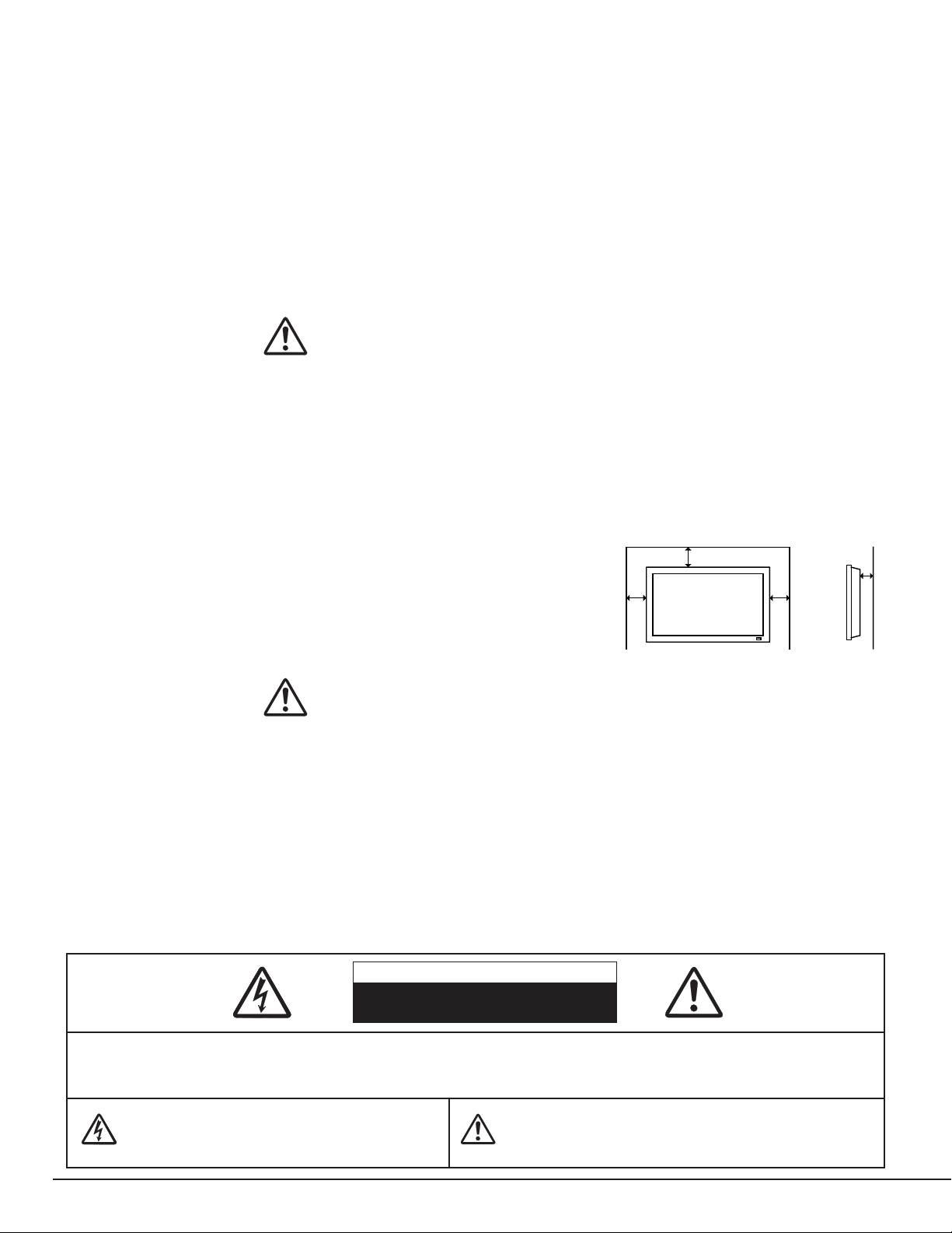
● This Plasma Monitor should be set in the way indicated. If not, it may result in a fire hazard.
● Take appropriate space on the top, sides and rear of the Plasma Monitor cabinet for allowing air circulation and cooling the
Plasma Monitor. Minimum distance should be taken. If the Plasma Monitor is to be built into a compartment or similarly
enclosed, the minimum distances must be maintained. Do not cover the
ventilation slot on the Plasma Monitor. Heat build-up can reduce the life
of your Plasma Monitor, and can also be dangerous.
● If the Plasma Monitor is not to be used for an extended time, unplug the
Plasma Monitor from the power outlet.
READ AND KEEP THIS OWNER'S MANUAL FOR LATER USE.
SIDE and TOP
CAUTION IN INSTALLING
●
Handle the
Plasma
Monitor carefully when installing it and do not drop.
●
Locate set away from heat, excessive dust, and direct sunlight.
●
For correct installation and mounting it is strongly recommended to use a trained, authorized dealer. Failure to follow
correct mounting procedures could result in damage to the equipment or injury to the installer.
10 cm
10 cm
10 cm
NOTE :
When Plasma Monitor is not used for a long period of time, unlighting dots may be observed. This is caused by characteristic of
the Plasma Monitor. If this occurs, turn the Plasma Monitor on and leave it on about 1 hour. These dots will gradually disappear.
6 cm

3
IMPORTANT SAFETY INSTRUCTIONS
Read these instructions.
Keep these instructions.
Heed all warnings.
Follow all instructions.
Do not use this apparatus near water.
Clean only with dry cloth.
Do not block any ventilation openings. Install in accordance
with the manufacturer's instructions.
Do not install near any heat sources such as radiators, heat
registers, stoves, or other apparatus (including amplifiers) that
produce heat.
Do not defeat the safety purpose of the polarized or
grounding-type plug. A polarized plug has two blades with one
wider than the other. A grounding type plug has two blades
and a third grounding prong. The wide blade or the third prong
are provided for your safety. If the provided plug does not fit
into your outlet, consult an electrician for replacement of the
obsolete outlet.
Protect the power cord from being walked on or pinched
particularly at plugs, convenience receptacles, and the point
where they exit from the apparatus.
Only use attachments/accessories specified by the
manufacturer.
Use only with the car, stand, tripod, bracket, or table specified
by the manufacturer, or sold with the apparatus. When a cart
is used, use caution when moving the cart/apparatus
combination to avoid injury from tip-over.
Unplug this apparatus during lighting storms or when unused
for long periods of time.
Refer all servicing to qualified service personnel. Servicing is
required when the apparatus has been damaged in any way,
such as power-supply cord or plug is damages, liquid has
been spilled or objects have fallen into the apparatus, the
apparatus has been exposed to rain or moisture, does not
operate normally, or has been dropped.
An appliance and cart combination
should be moved with care. Quick
stops, excessive force, and uneven
surfaces may cause the appliance and
cart combination to overturn.
Slots and openings in the back and top of the cabinet are
provided for ventilation, to insure reliable operation of the
equipment and to protect it from overheating.
Never push objects of any kind into this
Plasma Monitor
through cabinet slots as they may touch dangerous voltage
points or short out parts that could result in a fire or electric
shock. Never spill liquid of any kind on the
Plasma Monitor
.
This
Plasma Monitor
should be operated only from the type
of power source indicated on the marking label. If you are not
sure of the type of power supplied, consult your authorized
dealer or local power company.
Do not attempt to service this
Plasma Monitor
yourself as
opening or removing covers may expose you to dangerous
voltage or other hazards. Refer all servicing to qualified
service personnel.
Unplug this
Plasma Monitor
from wall outlet and refer
servicing to qualified service personnel under the following
conditions:
a. When the power cord or plug is damaged or frayed.
b. If liquid has been spilled into the
Plasma Monitor
.
c. If the
Plasma Monitor
has been exposed to rain or water.
d. If the
Plasma Monitor
does not operate normally by
following the operating instructions. Adjust only those
controls that are covered by the operating instructions as
improper adjustment of other controls may result in damage
and will often require extensive work by a qualified
technician to restore the
Plasma Monitor
to normal
operation.
e. If the
Plasma Monitor
has been dropped or the cabinet
has been damaged.
f. When the
Plasma Monitor
exhibits a distinct change in
performance-this indicates a need for service.
When replacement parts are required, be sure the service
technician has used replacement parts specified by the
manufacturer that have the same characteristics as the
original part. Unauthorized substitutions may result in fire,
electric shock, or injury to persons.
Upon completion of any service or repairs to this
Plasma
Monitor
, ask the service technician to perform routine safety
checks to determine that the
Plasma Monitor
is in safe
operating condition.
4
COMPLIANCE
The AC Power Cord supplied with this Plasma Monitor meets the requirement for use in the country you purchased it.
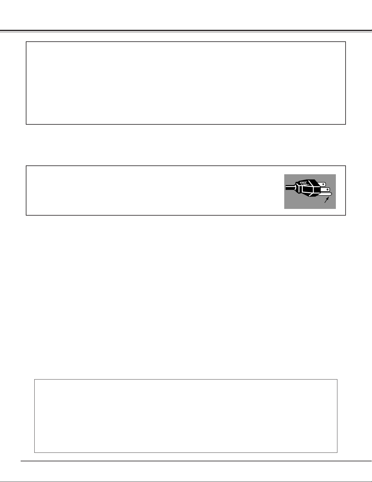
AC Power Cord for the United States and Canada :
AC Power Cord used in the United States and Canada is listed by the Underwriters
Laboratories (UL) and certified by the Canadian Standard Association (CSA).
AC Power Cord has a grounding-type AC line plug. This is a safety feature to be sure that the
plug will fit into the power outlet. Do not try to defeat this safety feature. Should you be
unable to insert the plug into the outlet, contact your electrician.
THE SOCKET-OUTLET SHOULD BE INSTALLED NEAR THE EQUIPMENT AND EASILY ACCESSIBLE.
AC POWER CORD REQUIREMENT
Declaration of Conformity
Model Number : PDP42H2W
Trade Name : Sanyo
Responsible party : SANYO Manufacturing Corporation
Address : 3333 Sanyo Road, Forrest City, AR 72335
Telephone No. : (870) 633-5030
This device complies with Part 15 of the FCC Rules. Operation is subject to the following two conditions :
(1) this device may not cause harmful interference, and
(2) this device must accept any interference received, including interference that may cause undesired operation.
● Do not bump or scratch the panel surface as this causes flaws on the surface of the screen.
● Do not display one non-movement still picture on the screen for a long time. Otherwise, an
afterimage or ghost may appear on a part of the panel. To prevent this symptoms, apply the screen
saver function in the Plasma Monitor.
● There may be some tiny black points and/or blight points on the Plasma Display Panel. These points
are normal.
CARE FOR USING PLASMA MONITOR
GROUND

5
TABLE OF CONTENTS
BEFORE OPERATION 16
COMPUTER MODE 29
VIDEO MODE 33
SETTING 34
APPENDIX 38
PREPARATION 6
NAME OF EACH PART OF PLASMA MONITOR 7
SETTING-UP PLASMA MONITOR 8
CONNECTING PLASMA MONITOR
11
TERMINALS OF PLASMA MONITOR 11
CONNECTING TO VIDEO EQUIPMENT 13
CONNECTING TO COMPONENT VIDEO EQUIPMENT
14
CONNECTING TO COMPUTER 15
OPERATION OF REMOTE CONTROL 16
SELECTING INPUT SOURCE 29
SELECTING COMPUTER SYSTEM 29
PC ADJUSTMENT 30
SELECTING INPUT SOURCE 33
PICTURE SETUP 34
INITIAL SETUP 35
SCREEN SAVER FUNCTION 36
INFORMATION MENU 37
CREANING THE PLASMA MONITOR 37
TROUBLESHOOTING 38
FUNCTIONS OF PRODUCT SAFETY FEATURES
39
TECHNICAL SPECIFICATIONS 41
BASIC OPERATION 18
TRADEMARKS
● Apple, Macintosh, and PowerBook are trademarks or registered trademarks of Apple Computer,Inc.
● IBM and PS/2 are trademarks or registered trademarks of International Business Machines, Inc.
● Each name of corporations or products in the owner's manual is a trademark or a registered trademark of its respective
corporation.
TURNING ON / OFF PLASMA MONITOR 18
OFF TIMER 19
WIDE SCREEN OPERATION 20
SELECTING INPUT SOURCE 21
PICTURE IMAGE LEVEL SELECT 22
OPERATING ON-SCREEN MENU 23
PICTURE ADJUSTMENT 26
SOUND ADJUSTMENT 27
SCREEN ADJUSTMENT 28
6
PREPARATION
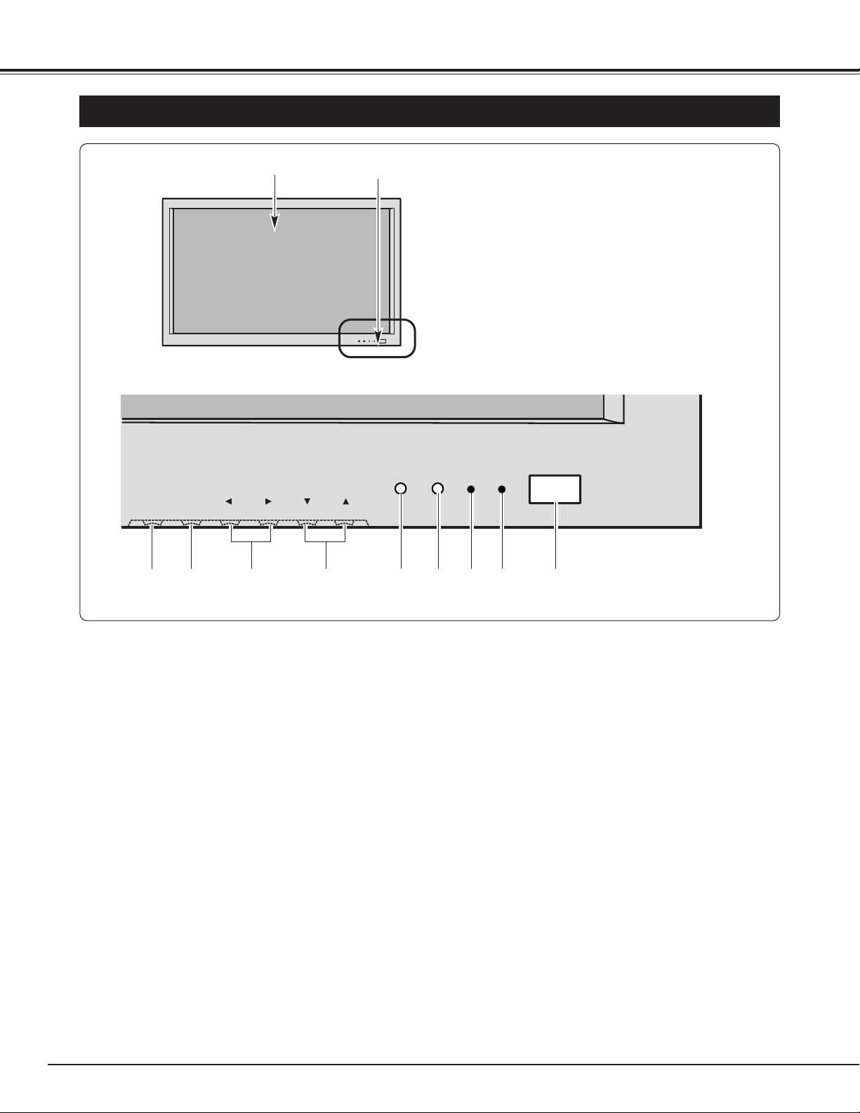
NAME OF EACH PART OF PLASMA MONITOR
!0 INPUT/ OK button
Used to select input source or execute the selected
menu on the On-Screen Menu. (P21, 23)
!1 MENU button
Used to open or close the On-Screen Menu. (P23)
y Infrared Remote Receiver
r
POWER indicator
Lights in green when power is on.
Lights in red when the power is off with the Remote
Control Unit (standby mode), or the Plasma Monitor is in
Power save mode. (P18)
i CURSOR (Up
ee
/Down
dd
) buttons
Used to select an item on the On-Screen Menu. (P23)
t OFF TIMER indicator
Lights in red when the Off timer function is on.
(P19)
e MAIN ON–OFF Switch
Used to turn Plasma Monitor on or off. (P18)
r
q
e
w
tyuio
o CURSOR (Left
77
/Right
88
) /VOLUME +/- buttons
Used to set or adjust the menu data on the On-Screen
Menu or adjust volume. (P23, 27)
Front
!0!1
q Plasma Display Panel
w Front Control and Indicators
u Light Sensor
Detects the ambient light to adjust the display brightness
and contrast. (P34)
OK
–+
INPUTMENU
VOLUME
4
7
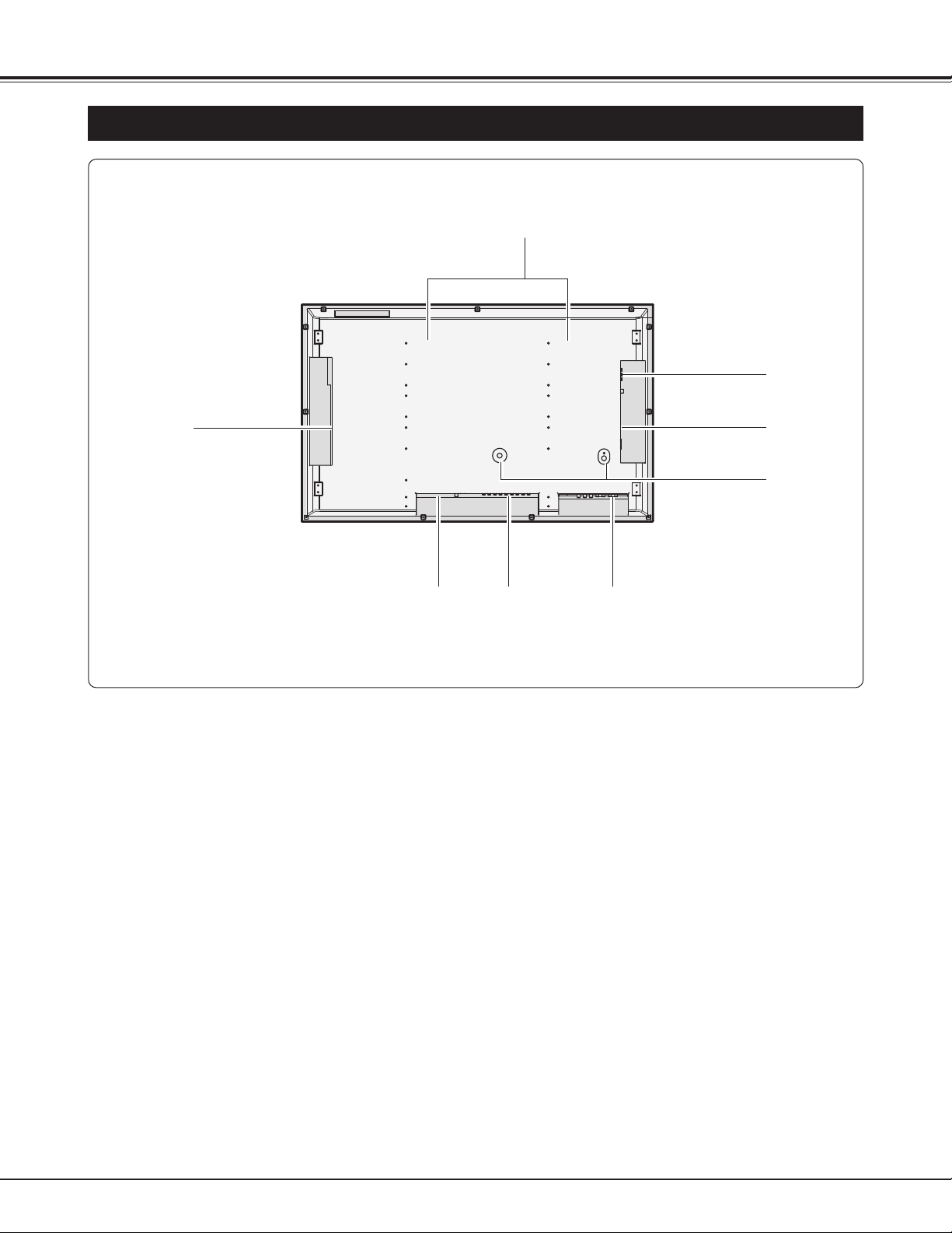
PREPARATION
NAME OF EACH PART OF PLASMA MONITOR
NOTE:
This Plasma Monitor detects internal temperature and automatically
controls operating power of Cooling Fans.
q Cooling Fan
Back
e
Speaker Output Terminals (Left Side)
(Refer to P10)
t Terminals and Connectors (Bottom Center)
(Refer to P12)
w Terminals and Connectors (Left Side)
(Refer to P11)
q
w
y
t
e
r
u
✽
✽ Terminals for Service
These terminals cannot be used in this equipment.
u Speaker Output Terminals (Right Side)
y Power Cord Connector
r Terminals and Connectors (Bottom Left)
(Refer to P12)
8
SETTING-UP PLASMA MONITOR
PREPARATION
This Plasma Monitor uses nominal input voltages of 100120 V AC. It is designed to work with single-phase power
systems having a grounded neutral conductor. To
reduce the risk of electrical shock, do not plug into any
other type of power system.
Consult your authorized dealer or service station if you
are not sure of the type of power supply being in use.
Connect the Plasma Monitor to the peripheral equipment
before turning on the Plasma Monitor. (Refer to P13 ~ 15
for connection.)
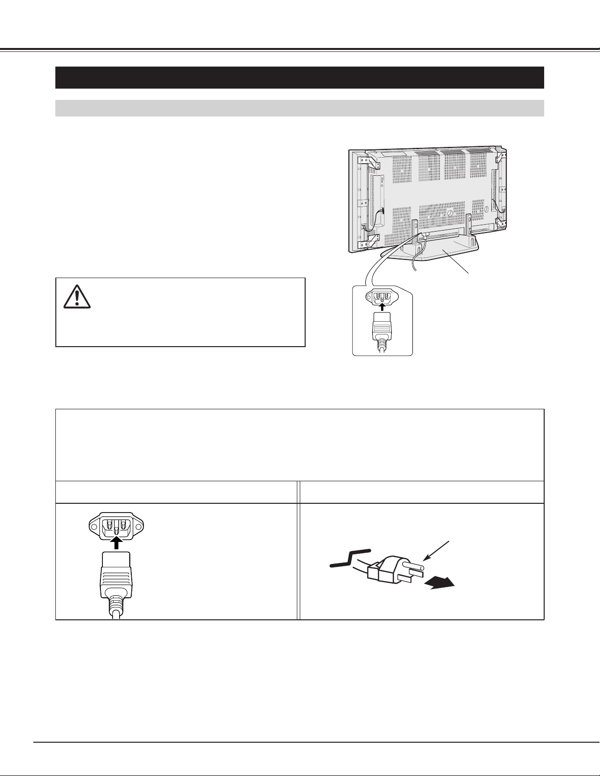
CAUTION
For safety, unplug the AC Power Cord when the
appliance is not used.
CONNECTING AC POWER CORD
Connect the AC Power Cord
(supplied) to the Plasma Monitor.
The AC outlet must be near this
equipment and easily accessible.
To the POWER CORD CONNECTOR
on Plasma Monitor
Plasma Monitor side AC Outlet side
Ground
NOTE ON THE POWER CORD
The AC Power Cord must meet the requirement of the country where you use the Plasma Monitor.
Confirm the AC plug type with the chart below and the proper AC Power Cord must be used.
If the supplied AC Power Cord does not match the AC outlet, contact your sales dealer.
To the AC Outlet.
(120 V AC)
Table Top Stand
9
PREPARATION
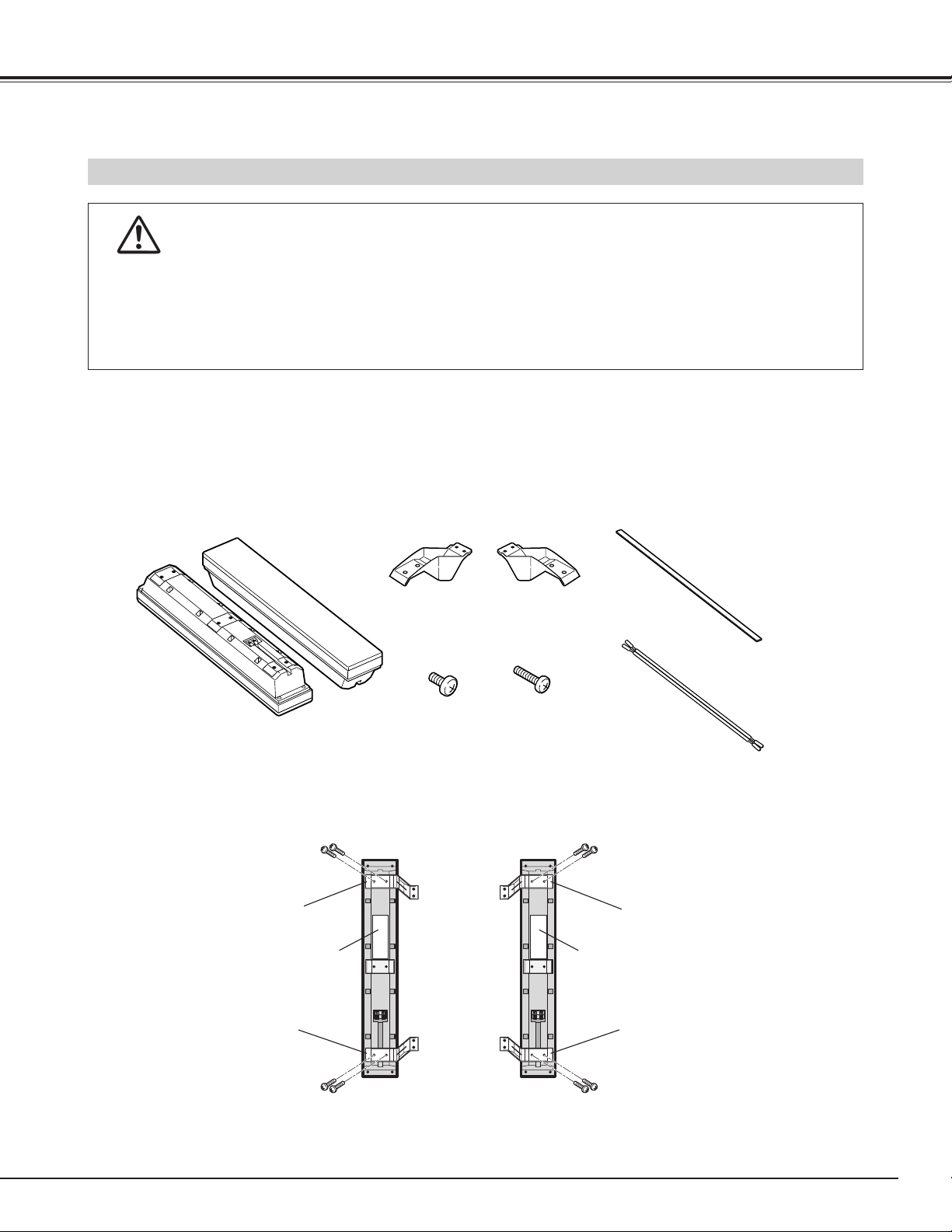
INSTALLATION OF THE SPEAKERS
● It is recommended that the installation work be done by more than two people.
● When holding (moving or lifting) the Plasma Monitor, hold the Monitor's body. Do not handle it by holding the
attached accessory parts (the Speakers), otherwise it may result in damage of the products.
● Leave sufficient space for the installation work.
CAUTION IN INSTALLATION
Speakers
(2pcs)
Brackets-A
(2pcs)
Brackets-B
(2pcs)
Large Screws
(5X12mm)
(8pcs)
Small Screws
(4X12mm)
(8pcs)
Soft Tapes
(2pcs)
Speaker Cables
(2pcs)
Before installation of the Speakers, check all the parts below are contained in the package.
1
Installation Procedures
Attach the brackets A and B to the Speakers with the large screws. Be sure each bracket is attached to the right
position of the speakers as below.
2
Speaker
Speaker
Bracket-B
Bracket-A
Bracket-A
Bracket-B
Large Screws
(2pcs)
Large Screws
(2pcs)
Large Screws
(2pcs)
Large Screws
(2pcs)
NOTE :
It is not required to differentiate the Right Speaker and the Left Speaker.
10
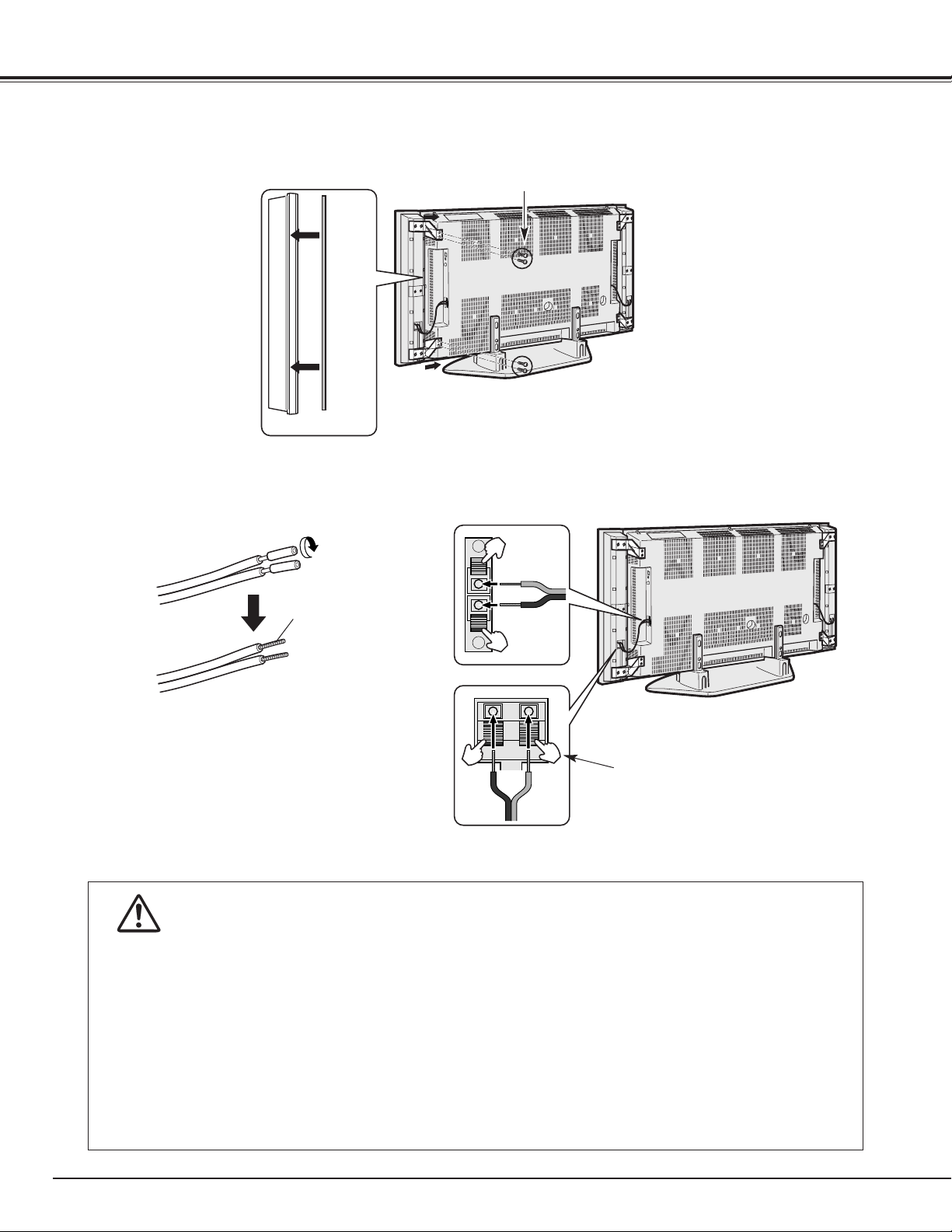
PREPARATION
Install the soft tape on the side of each speaker to contact the Plasma Monitor and fix the speakers to the Plasma
monitor with the small screws.
3
Speaker
Speaker
Soft Tape
Small Screws
(2pcs)
Small Screws
(2pcs)
Connect the Speakers and the Plasma Monitor with the speaker cables.
4
Red (+)
Black (-)
Red
(+)
Black
(-)
Speaker Cables
Twist the wires.
Take off the shield
of the cable end.
NOTE :
Take off the outer shield of the cable end and twist the
inside wires before connecting to the Plasma Monitor as
above.
NOTE :
Hold the terminal tab until the twisted
wires is fully inserted into the hole.
● Do not input over specified power otherwise damaging the Speakers and fire hazard may result.
● Do not locate under direct sun light or moistened place, the Speakers may be damaged.
● The Speakers are not provided with internal magnetic shield. Take a distance from equipment or appliances that
are influenced by magnetic field.
● For cleaning, please wipe lightly with a soft cloth. For heavy stains, carefully wipe with a cloth diluted neutral
detergent and finish off with a dry cloth.
● Wiping with a cloth containing oil or thinner may damage the fine surface. If using a chemically treated cloth,
please follow the instructions carefully.
● Do not spray volatile substances or any liquid, nor put rubber, adhesive tape, or vinyl object on the unit for long
periods of time. It may cause permanent damage to the unit or the fine surface.
CAUTION IN HANDLING THE SPEAKERS
11
CONNECTING PLASMA MONITOR
TERMINALS OF PLASMA MONITOR
This Plasma Monitor has INPUT and OUTPUT terminals on its left and right sides and back for connecting
computers and video equipment. Refer to P13 to 15 for connections.
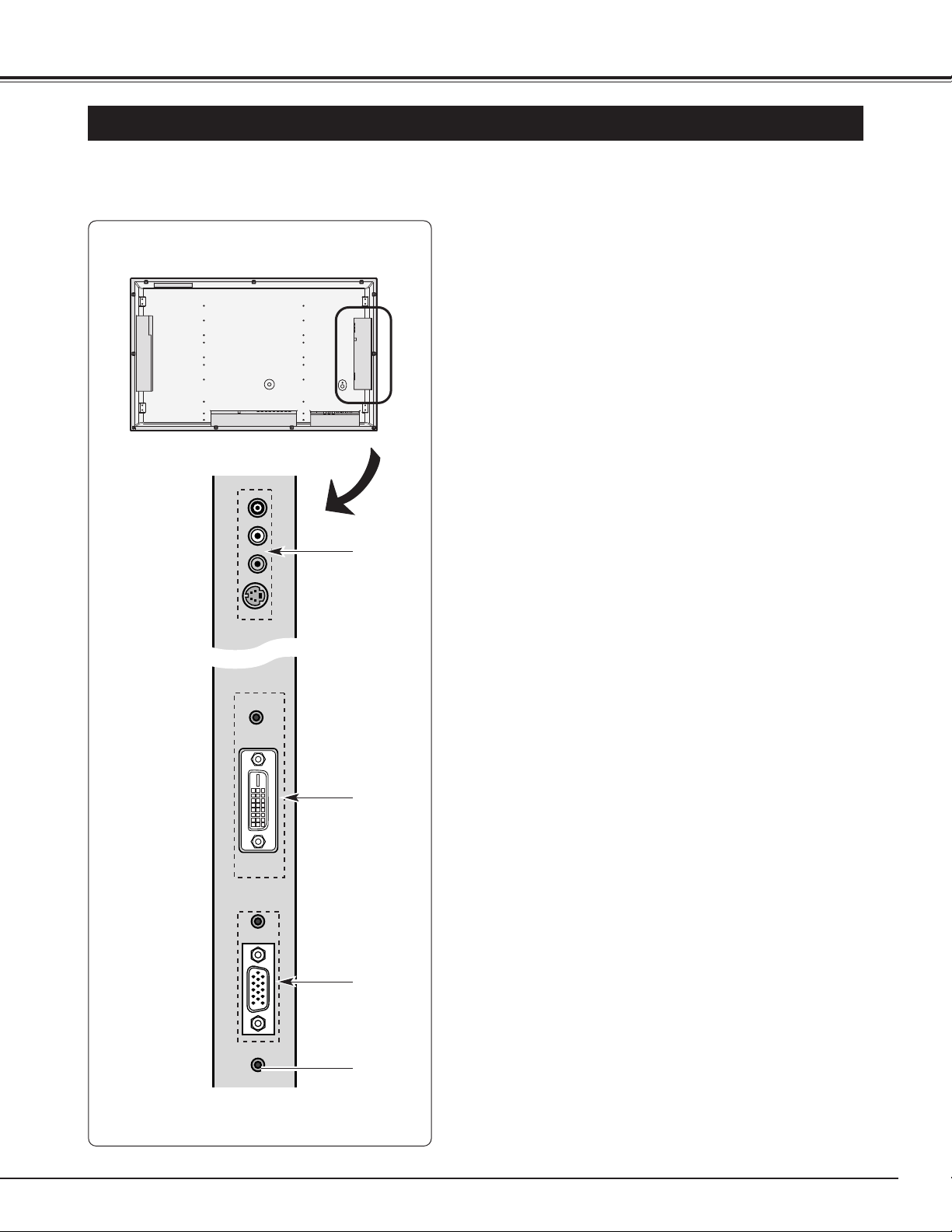
Side (Left)
q AV 3 IN Input Jacks
Connect video and audio outputs from a video
equipment. (Refer to P13.)
● AUDIO R and L(MONO) (RCA-type)
● VIDEO (RCA-type)
● S-VIDEO (Mini DIN 4-type)
e
COMPUTER IN Input Terminals
Connect computer and audio outputs to these terminals.
(Refer to P15.)
● AUDIO R/L (Stereo Mini Jack)
● RGB (D-SUB)
w DVI-D (HDCP/PC) IN Input Terminals
Connect DVI-D and audio outputs to these terminals.
(Refer to P15.)
● AUDIO R/L (Stereo Mini Jack)
● DVI-D (Digital)
r HEADPHONE Jack
Connect a headphone (stereo).
q
w
e
r
NOTE:
Video input jacks have the following priority.
When 2 cables are connected to one of the inputs and the other
inputs are disconnected, S-VIDEO jack has priority over VIDEO
jack.
NOTE:
The Speaker Outoput Terminals are provided for both sides of
the Plasma Monitor in addition to the terminals described above.
12
CONNECTING PLASMA MONITOR
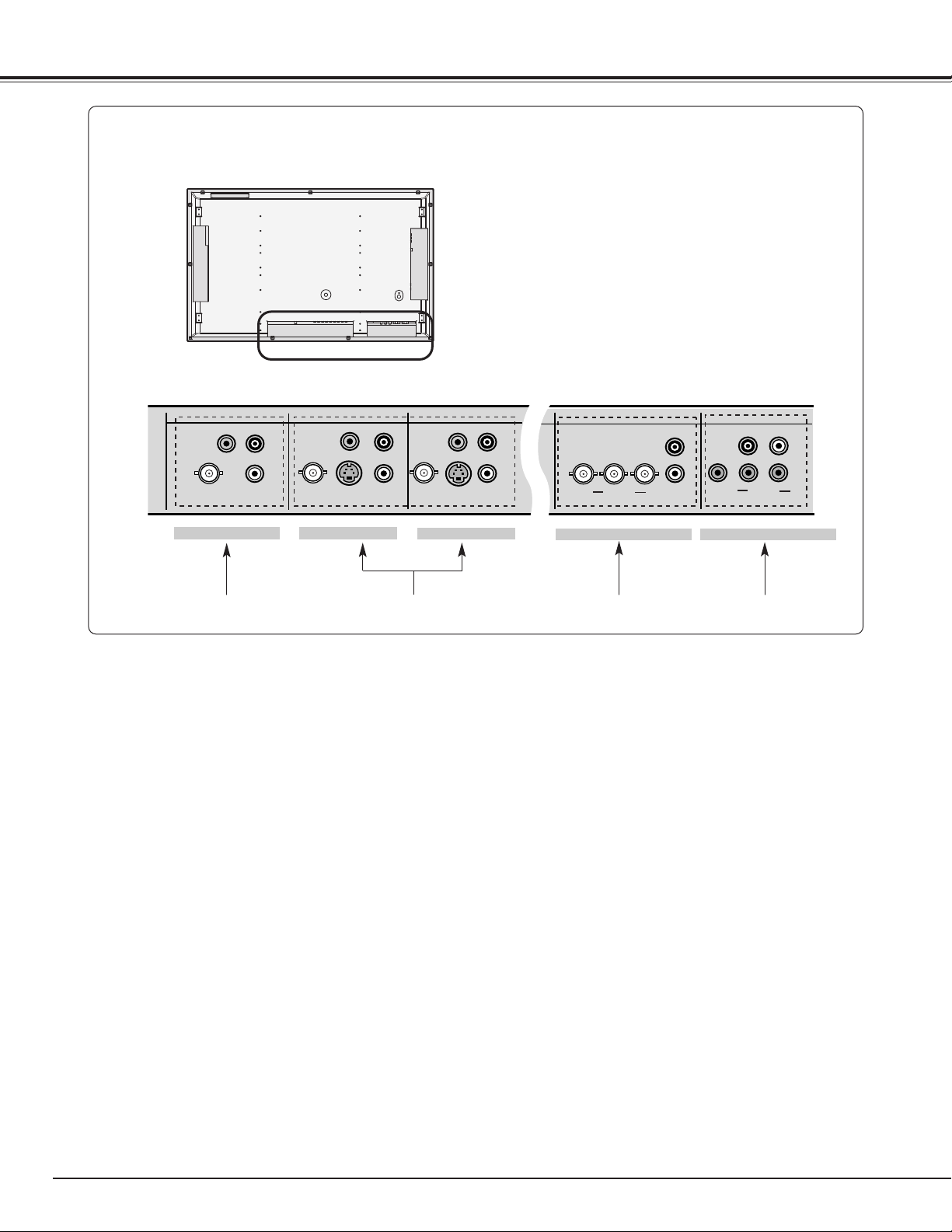
q
w e r
q Monitor Output Jacks
Connect another monitor, a video recorder or an external
audio amplifier to these jacks. (Refer to P13~15)
● VIDEO (BNC-type)
● VIDEO (RCA-type)
● AUDIO R and L (RCA-type)
These terminals are outputs for:
• Video and audio signals from VIDEO1-3 inputs
• Audio signals from PC ,DVI-D and COMPONENT1/2
IN inputs (Not for video signals)
NOTE:
Video input jacks have the following priority.
When 2 or 3 cables are connected to one of the inputs and the
other inputs are disconnected, S-VIDEO jack has priority over
VIDEO jack, and BNC jack has priority over RCA jack.
Back (Bottom Left and Center)
w AV 1 IN or AV 2 IN Input Jacks
Connect video and audio outputs from a video
equipment. (Refer to P13)
● VIDEO (BNC-type)
● VIDEO (RCA-type)
● S-VIDEO (Mini DIN 4-type)
● AUDIO R and L (RCA-type)
e COMPONENT1 IN Input Jacks
Connect component video and audio outputs to these
jacks. (Refer to P14)
● COMPONENT (BNC-type)
● AUDIO R and L (RCA-type)
r COMPONENT2 IN Input Jacks
Connect component video and audio outputs to these
jacks. (Refer to P14)
● COMPONENT (RCA-type)
● AUDIO R and L (RCA-type)
VIDEO
VIDEO
R
L
AUDIO
VIDEO
VIDEO
S-VIDEO
AUDIO
R
L
VIDEO
VIDEO
S-VIDEO
R
L
AUDIO
Pr/Cr Pb/Cb
Y
AUDIO
R
L
Pr/Cr Pb/Cb
R
AUDIO
L
Y
MONITOR OUT
AV 1 IN
AV 2 IN
COMPONENT 1 IN COMPONENT 2 IN
13
CONNECTING PLASMA MONITOR
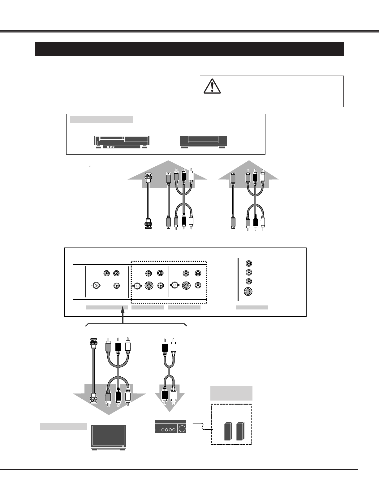
CONNECTING TO VIDEO EQUIPMENT
Video Source (example)
Video Cassette Recorder Video Disc Player
Video Cable
(RCA x 3)
S-VIDEO
Cable
Audio Speaker
(stereo)
S-VIDEO
Output
Audio Amplifier
Cables used for connection ( Cables are not supplied with this Plasma Monitor.)
• Video Cable (BNC x 1)
• Video Cable (RCA x 3)
• S-VIDEO Cable
• Audio Cable (RCA x 2)
NOTE :
When connecting the Plasma Monitor, AC Power
Cords of both the Plasma Monitor and external
equipment should be disconnected from the AC
outlet.
External Audio
Equipment
R L
S-VIDEO
VIDEO
Composite Video
and Audio Output
Audio Cable
(RCA x 2)
VIDEO and
AUDIO
R/L(MONO)
BNC Cable
Composite Video
and Audio Input
VIDEO
Input
External Monitor
Video Cable
(RCA x 3)
VIDEO and
AUDIO R/L
BNC
Cable
VIDEO
AUDIO
VIDEO
Output
SIDE TERMINALS
REAR TERMINALS
S-VIDEO VIDEO and
AUDIO
R/L(MONO)
S-VIDEO
Output
Composite Video
and Audio Output
Video Cable
(RCA x 3)
S-VIDEO
Cable
VIDEO
VIDEO
MONITOR OUT
AUDIO
R
AUDIO
L
VIDEO
S-VIDEO
AV 3 IN
AUDIO
R
VIDEO
L
S-VIDEO
VIDEO
AV 2 IN
R
L
VIDEO
VIDEO
S-VIDEO
AV 1 IN
R
L
AUDIO
14
CONNECTING PLASMA MONITOR
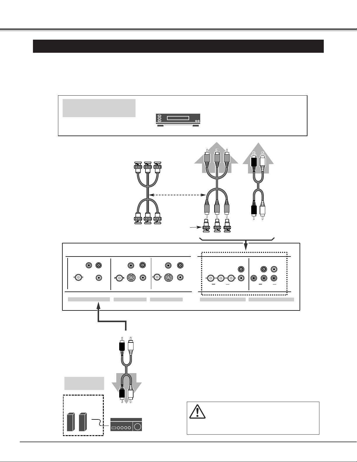
CONNECTING TO COMPONENT VIDEO EQUIPMENT
Component
Video Source
(example)
DVD player
Video Cable
(RCA x 3)
Cables used for connection (Cables are not supplied with this Plasma Monitor.)
• Video Cable (RCA x 3) or (BNC x 3)
• Audio Cable (RCA x 2)
• BNC/RCA Adapters (BNC x 3, Supplied)
NOTE :
When connecting the Plasma Monitor, AC Power
Cords of both the Plasma Monitor and external
equipment should be disconnected from the AC
outlet.
Audio Output
Y
Component video output equipment.
(such as DVD player or
high-definition TV source.)
Audio Cable
(RCA x 2)
Component Video
Output
Video
Cable
(BNC x 3)
Pr/Cr Pb/Cb
or
Audio Speaker
(stereo)
Audio Cable
(RCA x 2)
Audio Amplifier
External Audio
Equipment
R L
REAR TERMINALS
R L
BNC/RCA
Adapters
(Supplied)
VIDEO
VIDEO
R
L
AUDIO
VIDEO
VIDEO
S-VIDEO
AUDIO
R
VIDEO
L
S-VIDEO
VIDEO
AUDIO
R
L
Pr/Cr Pb/Cb
AUDIO
L
R
L
AUDIO
Y
R
Pr/Cr Pb/Cb
Y
MONITOR OUT
AV 1 IN
AV 2 IN
COMPONENT 1 IN COMPONENT 2 IN
 Loading...