

Page 1
INSTRUCTION MANUAL
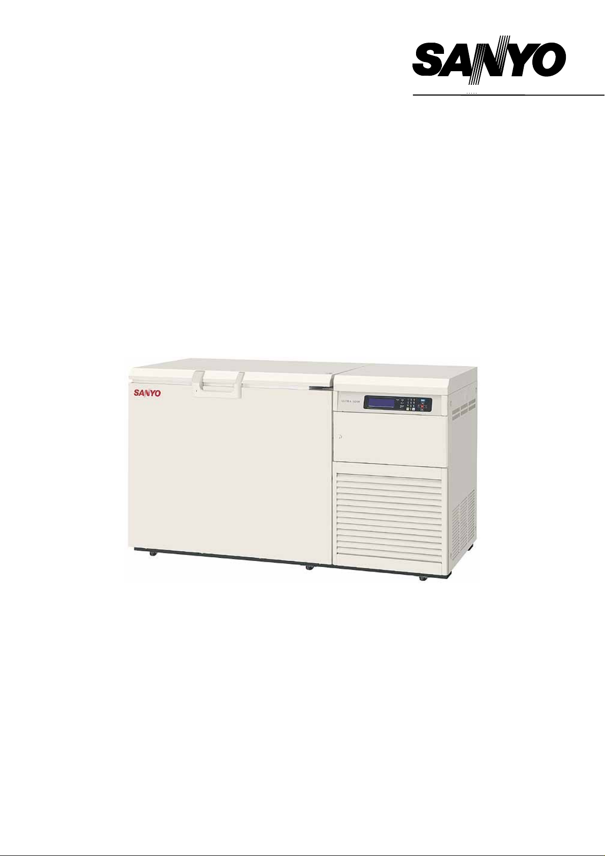
MDF-C2156VAN
Ultra-Low Temperature Freezer
MDF-C2156VANC
Page 2

CONTENTS
INTRODUCTION P. 2
PRECAUTIONS FOR SAFE OPERATION P. 3
ENVIRONMENTAL CONDITIONS P. 7
FREEZER COMPONENTS P. 8
Control panel P. 11
INSTALLATION SITE P. 12
INSTALLATION P. 13
START-UP OF UNIT P. 14
Operation after power failure P. 14
BASIC SCREEN OF CONTROL PANEL P. 15
FUNCTION OF CONTROL PANEL P. 15
RUNNING OPERATION (MENU/Set) P. 16
Key lock function P. 17
Key lock release function P. 17
VARIOUS SETTING (MENU/Log) P. 18
Display of log (Log) P. 18
VARIOUS SETTING (MENU/Tools) P. 20
Initialization (Tools/ Default Setting) P. 20
Date, Time, Set of log interval (Tools/Date Time) P. 21
Set of key lock password (Tools/Key lock PW Setting) P. 22
ALALRM BUZZER P. 22
MONITOR OF FREEZER STATUS P. 23
ALARMS & SELF-DIAGNOSIS FUNCTION P. 23
ALARMS & SAFETY FUNCTIONS P. 24
REMOTE ALARM TERMINAL P. 25
BACK-UP SYSTEM P. 25
ROUTINE MAINTENANCE
Cleaning of cabinet P. 27
Cleaning of condenser filter P. 27
Defrosting of inside wall P. 28
REPLACEMENT OF BATTERY P. 29
TROUBLESHOOTING P. 30
DISPOSAL OF UNIT P. 31
Recycle of battery P. 31
TEMPERATURE RECORDER (OPTION) P. 37
MOUNTING OF INTERFACE BOARD (OPTION) P. 40
SPECIFICATIONS P. 41
PERFORMANCE P. 42
SAFETY CHECK SHEET P. 43
1
Page 3

INTRODUCTION
■ Read this manual carefully before using the appliance and follow the instructions for safety operation.
■ Sanyo never guarantee any safety if the appliance is used for any objects other than intended use or
used by any procedures other than those mentioned in this manual.
■ Keep this manual in an adequate place to refer to it as necessary.
■ The contents of the manual will be subjected to change without notice due to the improvement of
performance or functions.
■ Contact Sanyo sales representative or agent if any page of the manual is lost or page order is incorrect.
■ Contact Sanyo sales representative or agent if any point in this manual is unclear or if there are any
inaccuracies.
■ No part of this manual may be reproduced in any form without the expressed written permission of
Sanyo.
2
Page 4
PRECAUTIONS FOR SAFE OPERATION
It is imperative that the user complies with this manual as it contains
important safety advice.
Items and procedures are described so that you can use this unit correctly and safely.
If the precautions advised are followed, this will prevent possible injury to the user and
any other person.
Precautions are illustrated in the following way:
WARNING
Failure to observe WARNING signs could result in a hazard to personnel
possibly resulting in serious injury or death.
CAUTION
Failure to observe CAUTION signs could result in injury to personnel and
damage to the unit and associated property.
Symbol shows;
Be sure to keep this manual in a place accessible to users of this unit.
< Label on the unit >
this symbol means caution.
this symbol means an action is prohibited.
this symbol means an instruction must be followed.
This mark is labeled on the cover in which the electrical components of high voltage
are enclosed to prevent the electric shock.
The cover should be removed by a qualified engineer or a service personnel only.
WARNING
As with any equipment that uses N2 gas, there is a likelihood of oxygen depletion in the vicinity
of the equipment. It is important that you assess the work site to ensure there is suitable and
sufficient ventilation. If restricted ventilation is suspected, then other methods of ensuring a
safe environment must be considered. These may include atmosphere monitoring and
warning devices.
3
Page 5
PRECAUTIONS FOR SAFE OPERATION
Do not use the unit outdoors. Current leakage or electric shock may result if the unit is exposed to
rain water.
Only qualified engineers or service personnel should install the unit. The installation by
unqualified personnel may cause electric shock or fire.
Install the unit on a sturdy floor and take an adequate precaution to prevent the unit from
turning over. If the floor is not strong enough or the installation site is not adequate, this may result
in injury from the unit falling or tipping over.
Never install the unit in a humid place or a place where it is likely to be splashed by water.
Deterioration of the insulation may result which could cause current leakage or electric shock.
Never install the unit in a flammable or volatile location. This may cause explosion or fire.
Never install the unit where acid or corrosive gases are present as current leakage or electric
shock may result due to corrosion.
Always ground (earth) the unit to prevent electric shock. If the power supply outlet is not
grounded, it will be necessary to install a ground by qualified engineers.
Never ground the unit through a gas pipe, water main, telephone line or lightning rod. Such
grounding may cause electric shock in the case of an incomplete circuit.
Connect the unit to a power source as indicated on the rating label attached to the unit. Use
of any other voltage or frequency other than that on the rating label may cause fire or electric shock.
Never store volatile or flammable substances in this unit if the cylinder cannot be sealed. These
may cause explosion or fire.
Do not insert metal objects such as a pin or a wire into any vent, gap or any outlet on the unit.
This may cause electric shock or injury by accidental contact with moving parts.
Use this unit in safe area when treating the poison, harmful or radiate articles. Improper use
may cause bad effect on your health or environment.
Turn off the power switch (if provided) and disconnect the power supply to the unit prior to any
repair or maintenance of the unit in order to prevent electric shock or injury.
Do not touch any electrical parts (such as power supply plug) or operate switches with a wet
hand. This may cause electric shock.
WARNING
4
Page 6
PRECAUTIONS FOR SAFE OPERATION
Ensure you do not inhale or consume medication or aerosols from around the unit at the time of
maintenance. These may be harmful to your health.
Never splash water directly onto the unit as this may cause electric shock or short circuit.
Never put cylinders with liquid on the unit as this may cause electric shock or short circuit when
the liquid is spilled.
Never bind, process, or step on the power supply cord, or never damage or break the power
supply plug. A broken supply cord or plug may cause fire or electric shock.
Do not use the supply cord if its plug is loose. Such supply cord may cause fire or electric shock.
Never disassemble, repair, or modify the unit yourself. Any such work carried out by an
unauthorized person may result in fire, or electric shock or injury due to a malfunction.
Disconnect the power supply plug if there is something wrong with the unit. Continued
abnormal operation may cause electric shock or fire.
When removing the plug from the power supply outlet, grip the power supply plug, not the cord.
Pulling the cord may result in electric shock or fire by short circuit.
Disconnect the power supply plug before moving the unit. Take care not to damage the power
cord. A damaged cord may cause electric shock or fire.
Disconnect the power plug when the unit is not used for long periods. Keeping the connection
may cause electric shock, current leakage, or fire due to the deterioration of insulation.
If the unit is to be stored unused in an unsupervised area for an extended period, ensure that
children do not have access and that doors cannot be closed completely.
The disposal of the unit should be accomplished by appropriate personnel. Remove doors to
prevent accidents such as suffocation.
Do not put the packing plastic bag within reach of children as suffocation may result.
WARNING
5
Page 7
PRECAUTIONS FOR SAFE OPERATION
Use a dedicated power source (a dedicated circuit with a breaker) as indicated on the rating label
attached to the unit. A branched circuit may cause fire resulting from abnormal heating.
Connect the power supply plug to the power source firmly after removing the dust on the plug.
A dusty plug or improper insertion may cause a heat or ignition.
Never store corrosive substances such as acid or alkali in this unit if the cylinder cannot be sealed.
These may cause corrosion of inner components or electric parts.
Check the setting when starting up of operation after power failure or turning off of power
switch. The stored items may be damaged due to the change of setting.
Be careful not to tip over the unit during movement to prevent damage or injury.
Prepare a safety check sheet when you request any repair or maintenance for the safety of service
personnel.
CAUTION
6
Page 8

ENVIRONMENTAL CONDITIONS
This equipment is designed to be safe at least under the following conditions (based on the IEC-1010-1):
■ Indoor use;
■ Altitude up to 2000 m;
■ Ambient temperature 5
■ Maximum relative humidity 80% for temperature up to 31
o
at 40
C;
■ Mains supply voltage fluctuations not to exceed ±10% of the nominal voltage;
■ Other supply voltage fluctuations as stated by the manufacturer;
■ Transient overvoltages according to Installation Categories (Overvoltage Categories) II; For mains
supply the minimum and normal category is II;
■ Pollution degree 2 in accordance with IEC 664.
o
C to 40oC
o
C decreasing linearly to 50% relative humidity
7
Page 9
FREEZER COMPONENTS
4
6
5
Inside of side table
7
1
15
27
10
17
9
32
5
Rear side
26
16
16
18
14
25
27
19
17
10
13
12
11
8
9
20
21
22
23
24
8
Page 10

FREEZER COMPONENTS
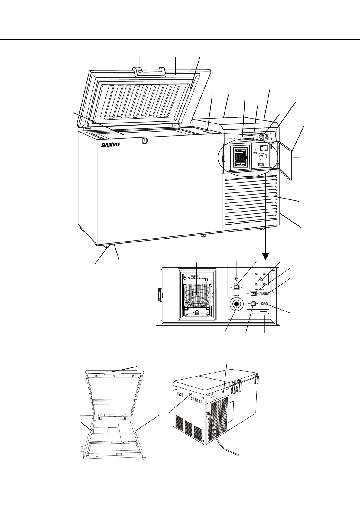
1. Lock: Turn clockwise to 180
2. Door: Hinged type. The door can be opened in any angle on the way to full open.
3. Magnetic door gasket: Seals the door and prevents leakage of cold air.
4. Inner lid: Serves as a means of reducing cold air leakage when the door is open.
5. Access port: Serves a means of leading the measuring cable from the freezing room to the outside.
6. Caster: 6 casters are provided. They make the moving of the unit easier.
7. Leveling foot: Serves to adjust the height and to settle the frame.
8. Grille: Acts as an inlet for air to cool the motor. Be careful not to block this. By pulling down this
grille, you can clean a clogged condenser filter. See page 27 for the details.
9. Exhaust air vent: Be careful not to block this.
10. Side table: A door can be opened. There are an access port and a remote alarm cable output port
in the inside.
11. panel door Lock: To lock the control cover to avoid the setting by accidental contact.
12. Panel door: There is a controller such as a power switch inside the panel door.
13. Control panel: Refer to page 11.
14. Digital temperature indicator: This indicator shows the present temperature or setting
temperature.
15. Temperature recorder (OPTION): Refer to page 38.
16. Back-up system joint: It is positioned at rear of the unit. Serves to connect with the pipelines
from the cylinder (liquid N
17. Remote alarm cable output port
18. Back-up test switch (TEST): Examine the functions of the back-up system. This switch allows
liquid N
19. Back-up switch (BACK UP): Switch on for operation of the back-up system and switch off for
stopping. Handle this switch according to page 26 “Back-up system”.
20. Communication box cover: Refer to “Mounting of interface board (OPTION)” on page 39 for
usage.
to spout under any circumstances. Handle it according to page 26 “Back-up system”.
2
2
o
with a key and the outer door is securely locked.
) at the top right of the rear frame. Refer to page 26 “Back-up system”
9
Page 11

FREEZER COMPONENTS
21. Remote alarm switch (REMOTE ALARM): This switch is for remote alarm. In case of operating
remote alarm, turn on the switch.
22. Remote alarm terminal (MAX DC30V 2A)
23. Analog output terminal (ANALOG VOLTAGE)
24. Power supply switch (POWER): Power switch of the freezer.
25. Battery switch: It is the switch of the battery for the power failure alarm. Turn it on usually. Turn
it off when you do not drive for a long time. (More than 1 month)
26. Temperature control knob (TEMP. SET(
the back-up system device.
27. Side table handle: There is a lever at the center of the front. when it is pulled to the front, the side
table is open.
o
C)): It is the knob which adjusts operation temperature of
10
Page 12
FREEZER COMPONENTS
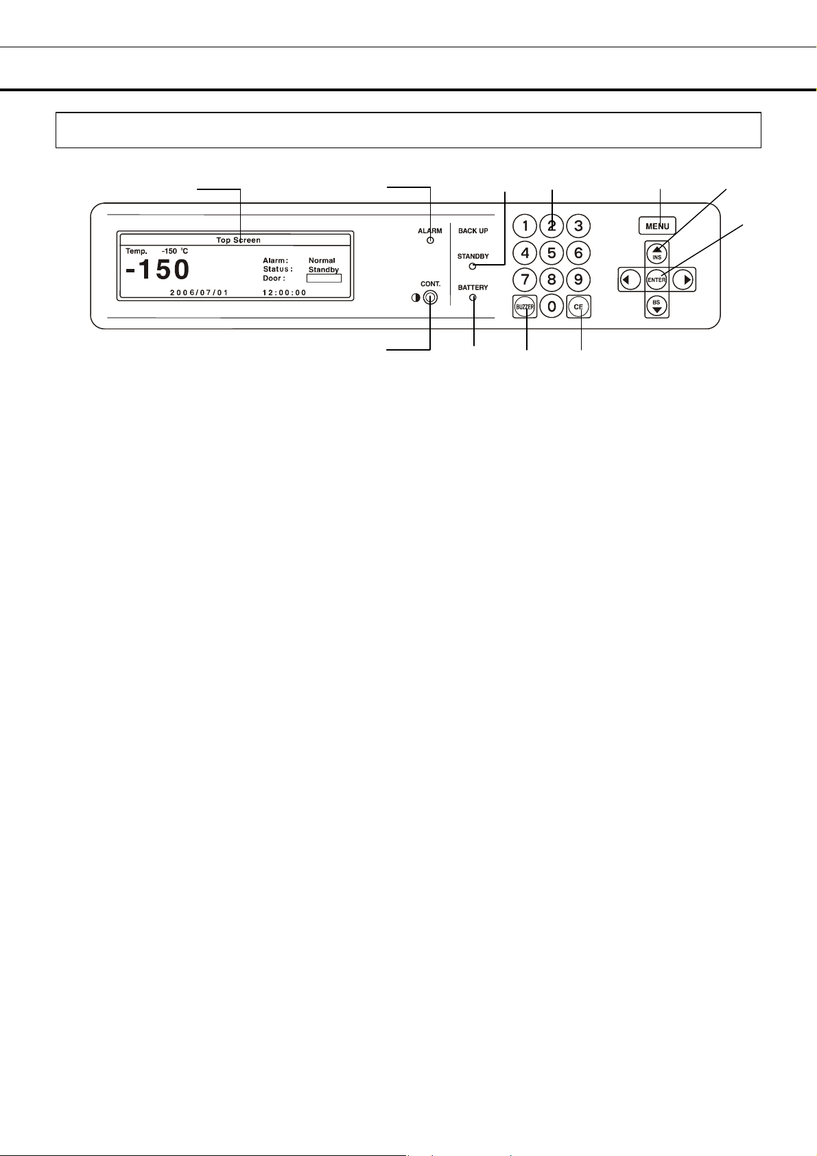
Control panel
1. LCD panel
1
o
C
Closed
2. Battery check lamp (BATTERY): This lamp lights when the battery capacity decreases at the power
failure. Batteries are expendable supplies. Replace a battery with every three years. For the
replacement, consult Sanyo sales representative or agent.
3. Alarm lamp (ALARM): This lamp flashes when the unit is in alarm condition.
4. Back-up lamp (STANDBY): This lamp lights when the back-up switch is on. (This doesn’t show
back-up system is activated.)
5. Figure input key: User for operation setting.
6. Menu button (MENU): To open the menu window.
7. Shift key (Upward, downward, rightward, leftward): To move the cursor on the LCD panel.
8. Enter key (ENTER): To determine the selection of menu.
9. Clear key (CE): To clear the input value during setting.
10. Alarm buzzer stop key (BUZZER):
- Buzzer stop key : Refer to P.22 for the details.
- Alarm test : Refer to P.15 for the details.
- Display of chamber temperature at power failure: Refer to P.24 for the details.
11. LCD contrast adjusting knob (CONT.): To adjust the contrast of LCD panel.
3
11
4
5
6
7
8
2
10 9
11
Page 13
INSTALLATION SITE
To operate this unit properly and to obtain maximum performance, install the unit in a location with the
following conditions:
■ A location not subjected to direct sunlight
Do not install the unit under direct sunlight. Installation in a location subjected to direct sunlight cannot
obtain the intended performance.
■ A location with adequate ventilation
Leave at least 10 cm around the unit for ventilation. Poor ventilation will result in a reduction of the
performance and consequently the failure.
■ A location away from heat generating sources
Avoid installing the unit near heat-emitting appliances such as a heater or a boiler etc. Heat can
decrease the intended performance of the unit.
■ A location with little temperature change
Install the unit under stable ambient temperature. The allowable ambient temperature is between -5 and
o
+35
C.
■ A location with a sturdy and level floor
Always install the unit on a sturdy and level floor. The uneven floor or tilted installation may cause failure
or injury. Install the unit in stable condition to avoid the vibration or noise. Unstable condition may
cause vibration or noise.
WARNING
Install the unit on a sturdy floor. If the floor is not strong enough or the installation site is not
adequate, this may result in injury from the unit falling or tipping over.
Select a level and sturdy floor for installation. This precaution will prevent the unit from tipping.
Improper installation may result in water spillage or injury from the unit tipping over.
■ A location not prone to high humidity
Install the unit in the ambient of 80% R.H. or less humidity. Installation under high humidity may cause
current leakage or electric shock.
WARNING
Do not use the unit outdoors. Current leakage or electric shock may result if the unit is exposed to
rain water.
Never install the unit in a humid place or a place where it is likely to be splashed by water.
Deterioration of the insulation may result which could cause current leakage or electric shock.
■ A location without flammable or corrosive gas
Never install the unit in a flammable or volatile location. This may cause explosion or fire or may result
in the current leakage or electric shock by the corrosion of the electrical components.
■ A location without the possibility of anything fall
Avoid installing the unit in the location where anything can fall down onto the unit. This may cause the
breakdown or failure of the unit.
12
Page 14
INSTALLATION
1. Removing the packaging materials and tapes
Remove all transportation packaging materials and tapes. Open the doors and ventilate the unit. If the
outside panels are dirty, clean them with a diluted neutral dishwashing detergent. (Undiluted detergent
can damage the plastic components. For the dilution, refer to the instruction of the detergent.) After
the cleaning with the diluted detergent, always wipe it off with a wet cloth. Then wipe off the panels with
a dry cloth.
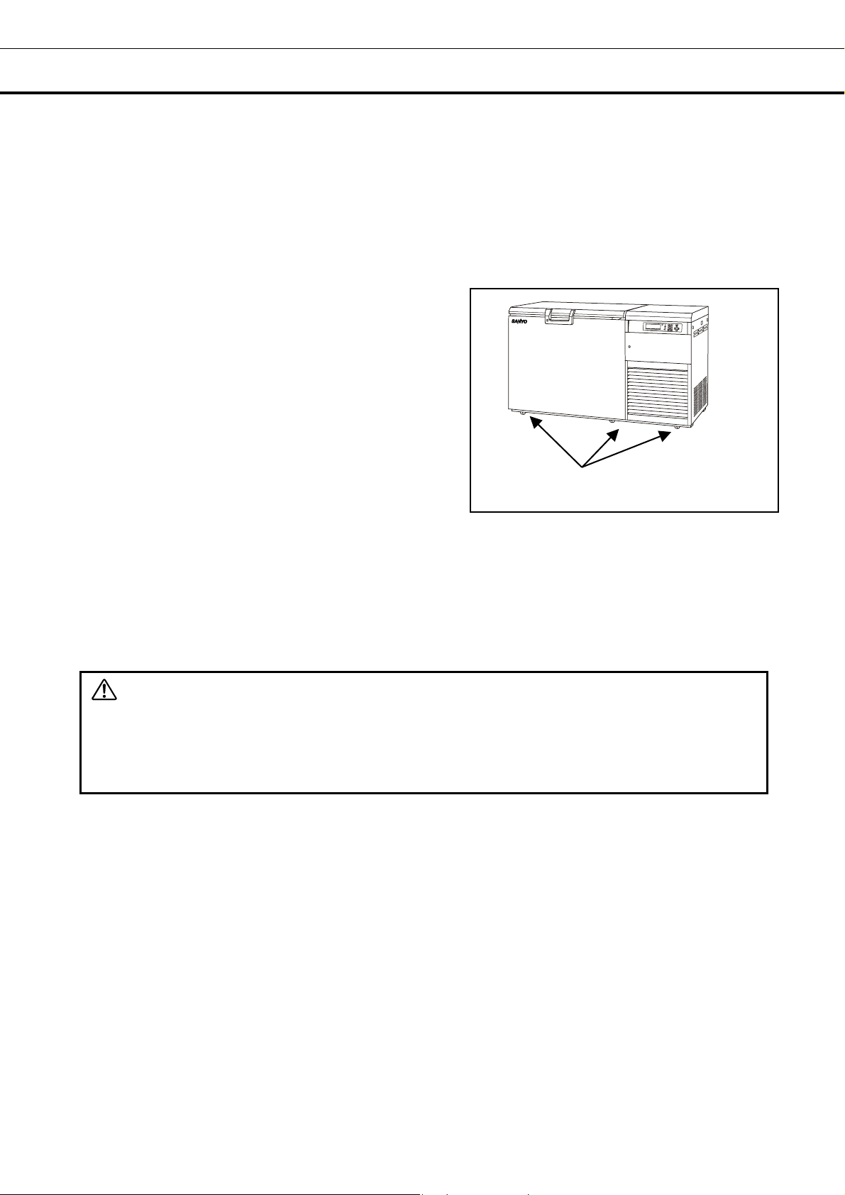
2. Adjusting the leveling foot
Extend the leveling feet by rotating them counterclockwise
to contact them to the floor. Ensure the unit is level.
3. Fixing the unit
Two fixtures are attached to the rear of the frame.
Fix the frame to the wall with these fixtures and rope or
chain.
4. Ground (earth)
The ground (earth) is for preventing the electric shock in the case of the electrical insulation is somehow
degraded. Always ground the unit at the time of installation.
Leveling foot
WARNING
Use a power supply outlet with ground (earth) to prevent electric shock. If the power supply outlet is
not grounded, it is necessary to install a ground by qualified engineers.
Never ground the unit through a gas pipe, water main, telephone line or lightning rod. Such
grounding may cause electric shock in the case of an incomplete circuit.
13
Page 15

START-UP OF UNIT
Follow the procedures for the initial and consequent operations of the unit.
1. Confirm that all switches kinds (power supply switch, battery switch, remote alarm switch and back-up
system switch) are off.
2. Set liquid N
3. Put the inner lid, close the door, and connect a power cord to the power supply.
4. Turn on the power supply switch. The chamber temperature is indicated.
5. Set up the temperature with the temperature control knob when using a back-up system.
6. Turn on the battery switch, remote alarm switch and back-up switch.
7. Push the alalm buzzer stop key (BUZZER) for about 5 seconds, and confirm the flashing of the alarm
lamp and a buzzer sound. When it is pushed again, an alarm test movement is finished.
8. Push the back-up test switch, and confirm that liquid N
9. Turn off a remote alarm switch and a back-up switch when temperature of the sample is high. Then,
turn on these switches under the condition that a sample is refrigerated again.
gas cylinder.
2
flows into the freezer.
2
Operation after power failure
The set value is memorized by nonvolatile memory. Accordingly, the chamber resumes the operation
with setting before power failure. During the power failure, the clock function is operating.
■ Change a setting as necessary because the freezer resumes with -150
discharged.
o
C setting if the battery is
14
Page 16

BASIC SCREEN OF CONTROL PANEL
m
When the power supply switch is turned on, the basic screen of the control panel is indicated. The
numerical value after "Temp" shows set temperature, and a big number under that shows present
chamber temperature. The bottom shows a present date and time.
01 0
4
5
6
2
Top Screen
1
T e
2
Alarm: N
3
S
4
−150
5
2 0 0 6/ 07/ 01 12: 00: 00
6
p - 1 5 0 o C
7
1. Display of alarm (Alarm): An “Alarm” is indicated alternately in the reversal/non-reversal character
during the alarm operation. Warning is indicated alternately in the reversal/non-reversal character at the
time of warning. “Normal” is usually indicated. The complementary message is indicated in the
message column.
・ “Test” is indicated alternately at the alarm test by the reversal/non-reversal.
2. Display of status (Status): The message of the indication (Status) of the status number and the
complement is indicated in the message column. An error message is indicated at the time of warning.
Refer to P.23 for the details. “Stand-by” is usually indicated.
3. Display of door status (Door): “Door” is highlighted when the door is open. When a door is close,
it is indicated with "Closed". (usual character)
4. Display of setting (Temp): Set value of chamber temperature is displayed.
5. Display of current value: Current value of chamber temperature is displayed.
6. Message indication: Various messages are indicated. Refer to P.23 for the details.
7. Display of date and time: The current date and time are displayed.
11 12 13 14 15161718192021222324252627282930313233343536 37 38 39 4
℃
D
or ma l
tatus: St an d - b y
oor: Close d
0
1
2
3
FUNCTION OF CONTROL PANEL
The following functions are available through control panel:
1. Setting of standby operation: To set a running condition at the start-up.(refer to P.16)
2. Setting of log cycle and sending to PC: To set a log cycle of running data and to send a running
log to PC. (P.18)
3. Setting of date and time: To set the date and time shown on the basic screen.(P.21)
4. Setting/display of alarm: High limit (or low limit) temperature setting(P.15). Power failure alarm
(P.23) and filter alarm (P.23) are indicated.
5. Default setting: To set the default for LCD panel and communication (DAQ) speed etc.(P.20)
6. Alarm test: The test of alarm buzzer, alarm lamp and remote alarm is effective by pressing the alarm
buzzer stop key (BUZZER) for about five seconds during normal operation. Pressing the key again
finishes the alarm test.
15
Page 17

RUNNING OPERATION(MENU/Set)
This product is operated with set temperature at the time of start-up.
1. With the basic screen displayed, press the menu button (MENU) to show the menu window. Select
“Set”, and press the enter key (ENTER).
2. A temperature setup screen (Temp. Setting) is indicated. Set up each parameter.
3. Push a menu button (MENU) to finish the settlement of each parameter. Select OK on the menu
window, and push the enter key (ENTER). The setting is memorized.
Each parameter setting range:
●Temperature : It is the set point of chamber temperature. Temperature settable range : -125〜-155oC
(The factory setting is -150
●High Alarm: It is the set point of the high temperature alarm. Temperature settable range: Chamber
temperature +5〜+20
●Low Alarm: It is the set point of the low temperature alarm. Temperature settable range: Chamber
temperature -5〜-20
●Ring Back: This is the duration between the stop of alarm buzzer and next start of alarm buzzer. The
settable range is between 1 minute and 99 minutes. The alarm buzzer is not back again when the
setting is 0. (The factory setting is 15 minutes)
●Door Delay: The settable range of the door alarm delay time is 1 minute and 15 minutes. (The factory
setting is 2 minutes)
●Key Lock: When "Lock" is chosen, a set point can not be changed. The input of the password is
necessary at the time of release.
Note : An alarm buzzer operates 15 minutes after it became a state of alarm. When a door is open,
it is indicated on the basic screen (Door) by "Open" and the reversal.
o
C (The factory setting is +10oC)
o
C (The factory setting is -10oC)
o
C.)
16
Page 18

RUNNING OPERATION(MENU/Set)
Key lock function
1. On the temperature setting screen (Temp. screen), input 1 in the “Key Lock” field. Press the enter
key (ENTER) and the buzzer sounds shortly and the key lock is effective.
2. “Key Lock” is indicated on the top line. The change of setting is impossible.
Key Lock
1
Key lock release function
1. On the temperature setting screen (Temp. Setting), input 0 in the “Key Lock” field, and press the
enter key (ENTER).
2. The cursor is moved to the password column (Password). Input 4-digit password and press the
enter key (ENTER). The buzzer sounds shortly and the key lock is released. The “Key Lock” indication
of the temperature setting screen (Temp. Setting) disappears.
01 0
2
T e mp . S e t t i n g
1
T e mp e r a t u r e - 1 5 0
2
Hi g h A l a r m + 1 0
3
Lo w A l a r m - 10
4
R i n g B a c k 1 5 mi n ( 0 . O F F 1 - 9 9 m i n )
5
Do o r D e l a y 2min (1-15mi n)
K e y L o c k 0 P a s s w o r d
6
11 12 1314151617181920212223242526272829303132333435363738 39 4
Note : The buzzer sounds if a password is wrong. Again, input a password. A user should manage a
password with all of the members. Factory setting is 0000. Refer to P.22.
Key Lock
1
K e y L o c k
Key Lock
o
C ( - 1 2 5oC -155oC)
o
C ( 5oC- 2 0oC)
o
C ( 5oC- 2 0oC)
0
17
Page 19

VARIOUS SETTING (MENU/Log)
Display of log(Log)
1. On the basic screen, press the menu button (MENU) to show the menu window. Select log, and
press the enter key (ENTER).
2. When accumulated data (for one day) are transmitted to the PC: Press the menu (MENU), select “PC
1D” and press the enter key (ENTER). When all accumulated data are transmitted to the PC: Press the
menu button(MENU), select “PC ALL” and press the enter key (ENTER). All accumulated records are
indicated with a dot. A graph display (PC 1D) is indicated. (1 page 24-hour indication)
3. Data transmitting screen is indicated. Specify a transfer, a capture of the textbook and a preservation
file name by the operation on the PC side hyper-terminal. Specify the extension of the preservation file
name with txt or csv. Press the menu button (MENU), select “start” and press the enter key (ENTER).
The transmission is started. The transmission is finished when a finished message comes out.
01 02 03 04 05 06 07 08 091011 12 13 14 15 16 17 18 19 20 212223242526272829303132333435363738394
P r o g r e ss
1
3
S e n d l og d a t a t o P C.
4
L o g D a t e 2 0 0 6 / 0 7 / 0 1
5
F i n i s h ed .
6
Each parameter setting range:
●Temperature range is changed with ↓↑. Temperature :50〜-25
●It is moved with ← and → to date. (←: Past date, →: New date)
●A data interval is 2 minutes from 30 minutes. (The factory setting is 15 min..)
With 15 minutes interval, the recording for about 5 weeks is available. With 6 minutes interval, the
recording for about 2 weeks is possible.
●Pop-up screen is indicated when “PC 1D” is selected. Log data on date (for 1 day) indicated.
●Pop-up screen is indicated when “PC ALL” is selected and all memory log data are transmitted.
●Pop-up screen is indicated when the clear key (CE) is pushed. All log data are erased when OK is
selected by pop-up MENU.
Note :
●When log data are full, it is erased automatically in order from the old data.
●The communication cable for the interface board MTR-480 of the option and 9 pin Dsub cross type for
RS232C is necessary for the data transmission to the PC. Refer to P. 40 for the details.
2006 / 06 / 30
2006 / 06 / 30
MENU
St ar t
Cancel
0
o
C、-25〜-100 oC、-100〜-175 oC
18
Page 20

VARIOUS SETTING (MENU/Log)
The operation of the hyper-terminal on the PC side
1. Transmission starts when a transfer, a capture of the text and a preservation file name are specified
and MENU/Start is selected.
2. The transmission is finished, with “Finished” indication.
Setup of communication: Log data receipt on the PC side (In case of Windows 2000 and XP)
1. Start a program-accessories-communication-hyper-terminal from the starting button. The registration of
the starting menu is to start in the following method, C : Start from ¥Program Files¥ Windows
NT¥hypertrm.exe.
2. Set up the following through the hyper-terminal screen.
●New connection Name (Example) Sanyo
●Setup of the connection Connection port COM1
●Properties of COM1 Setup of the port
●Bit/sec.: 9600 Data bit: 8 Parity: No Stop bit: 1 Flow control: Xon/Xoff
(When a log transmitting screen is opened, terms of communication on the MDF side are set on the
above condition automatically.)
3. The communication cable for the interface board MTR-480 of the option and 9 pin Dsub cross type for
RS232C is necessary for the data transmission to the PC. Refer to P. 40 for the details.
19
Page 21

VARIOUS SETTING(MENU/Tools)
m
m
Various numerical value can be changed from Tools.
1. On the basic screen, press the menu button (MENU), select “Tools” and press the enter key (ENTER).
The setting screen “Select Tools” is displayed.
2. Select the item to be set and press the enter key (ENTER).
01 0
2
T o p S c reen
1
T e m p - 1 5 0
2
Alarm: N
3
S
4
−150℃
5
2 0 0 6 / 0 7 / 0 1 1 2 : 0 0 : 0 0
6
01 02 03 04 05 06 07 080910 11 12 13 14 15 16 17 18 19 20212223242526272829303132333435363738394
S e l e c t T o o l s M D F - 2 1 5 6
1
3
D e f a u lt S e t t i n g
D a t e T i me
4
K e y L o c k S e t t i n g
5
Key Lock PW Setting
L o c k S e t t i n g
6
11 12 13 14 15 16 17 18 19 20212223242526272829303132333435363738394
o
C
D
tatus: St andby
oor : Cl osed
MENU
Set
or mal
Log
T o o l s
MENU
O K
Svc
Canc el
0
0
Initialization(Tools/Default Setting)
1. The settlement of each parameter can be done on the default setting screen (Default Setting). (The
following shows the default setting)
2. After setting, press the menu button (MENU), select “OK” and press the enter key (ENTER) The
setting is memorized.
Each parameter setting range:
●LCD Back Color : Setup of the back light (1. Blue 2. White)
●DAQ Speed should use 0, “2400”. It is DAQ standard command mode.
●DAQ ID: select any ID between 1 and 250 when an optional interface beard is attached.
●DAQ Mode: “0” setting change from PC side is impossible. “1” change of temperature on the stand-by
setting” screen is impossible. “Remote” is indicated on the upper right of the “Stand-by setting” screen.
DAQ Mode is effective when DAQ speed is 0 or 2.
●Filter Buzzer can select ON-OFF of the buzzer sound at the time of the filter alarm.
●Remote Alarm can select ON-OFF of the remote alarm at the time of the alarm.
01 02 03 04 05 06 07 08 09 1011 12 13 14 15 16 17 18 19 20 21 2223242526272829303132333435363738394
D e f a u l t S e t t i n g
1
L C D B a c k C o l o r
3
D A Q S p eed 0 ( 0. 2400 2. 9600)
D A Q I D 0 ( 0 . O f f 1 - 2 5 5 )
4
D A Q M o de 0 ( 0.Local 1.Re
5
F i l t e r Bu z z e r 1 ( 0.Off 1.Active)
R e m o t e A l a r
6
1 ( 1 . B l u e 2 .Wh i t e)
1 ( 0.Off 1.Active)
MENU
O K
Cancel
ot e)
0
20
Page 22

VARIOUS SETTING (MENU/Tools)
m
M
m
m
m
m
y
Setting of date, time, log interval(Tools/Date Time)
1. A date, time and a log interval setup screen (Data Time) is indicated. Set up each parameter.
2. After setting, press the menu button (MENU), select “OK” and press the enter key (ENTER). The
setting is memorized.
Each parameter setting range:
●July 1st, 2006 12:00:00 is set.
It is input with 060701 in the Date cell.
It is input with 120000 in the Time cell.
It is set up with MENU/ OK (ENTER).
●Log Interval: Settable between 2 minutes and 30 minutes. (Factory setting is 15 minutes.) With 15
minutes interval, recording for about 5 weeks is available.
●Comp Delay: Delay time for high temperature side/low temperature side compressor after power failure.
The settable range is between 2 minutes until 30 minutes. (Factory setting is 2 minutes.)
01 02 03 04 05 06 07 0809 10 11 12 13 14 15 16 17 18 1920212223242526272829303132333435363738394
D a t e T i
1
3
D a t e 0 6 / 0 7 / 0 1 ( Y Y /
T i me 1 2 : 0 0 : 0 0 ( h h :
4
5
L o g I n t e r v a l 6
Comp Dela
L . C o
6
e
M/DD)
: s s )
15
p D e l a y 5 min (2-15min)
in (2-30min)
MENU
O K
Canc e l
0
21
Page 23

VARIOUS SETTING (MENU/Tools)
W
W
w
W
Setting of key lock password(Tools/Key Lock PW Setting)
1. On the setting screen (Select Tools), select “Key Lock PW Setting”, select “OK” and press the enter
key (ENTER). Input the present password (4 digits), select “OK” and press the enter key (ENTER).
(Factory setting is 0000.)
2. Input a new password, select “OK” and press the enter key (ENTER).
3. Input the password again, select “OK” and press the enter key (ENTER).
01 0203 04 05 06 07 08 09 10 11 12 13 14151617181920212223242526272829303132333435363738394
K e y L o c k . P
1
C u r r e n t U s e r P a s s w o r d
4
5
6
01 0203 04 05 06 07 08 09 1
K e y L o c P .
1
4
5
6
1
4
5
6
U s e r P a s swor d
N e
010203 04 05 06 07 08 09 10 11 12 1314151617181920212223242526272829303132333435363738394
K e y L o c k . P
N e w U s e r P a s s w o r d ****
R e E n t e r U s e r P a s s w o r d
Setting
1 1 1314151617181920212223242526272829303132333435363738394
0 1 2
Setting
k
Setting
0
0
0
ALARM BUZZER
●Temperature alarm buzzer (intermittent tone)
It is informed with the intermittent tone of the buzzer when a high temperature alarm (High Alarm) or a
low temperature alarm (Low Alarm) occur.
Buzzer informs it with the intermittent sound when an alarm condition goes on for more than fifteen
minutes. Push alarm buzzer stop key (BUZZER) to stop the alarm. The alarm buzzer sounds again if
an alarm isn't solved in the time when it is set up with Ring Back. When alarm sounds, a remote alarm
is activated, too.
●Door alarm buzzer (intermittent tone)
It is informed with the intermittent tone if it is the condition that the door opens beyond the time when it is
set up with Door Delay. It stops if a door is closed.
●Filter alarm buzzer (intermittent tone)
It is informed with the intermittent tone when the temperature of filter sensor is beyond +48.0
Buzzer sound stops when the temperature of the filter sensor is less than +43.0
o
C
※:Buzzer stops if the alarm buzzer stop key (BUZZER) is pushed when an alarm occurs and a buzzer
sounds.
o
C
22
Page 24

MONITOR OF FREEZER STATUS
This product has the operation monitor system which shows it in the table 1. It is the system to inform it
of the operation conditions of the product. Operation conditions are indicated in the Status indication of
the basic screen and the message indication.
Table 1 Operation monitor system(STATUS) list
Kind of function Status Indication If this status continues Remedy
STATUS indication :
Notice of
abnormal
ambient
temperature
Notice of low
voltage
Note:
・Buzzer operation and a remote alarm can not be done with the monitor of the freezer status.
・STATUS indicates only "STATUS_1" when two problems occur in the monitor of the freezer status.
STATUS indicated is to cope with it.
When the ambient
temp. is over approx.
o
35
C or lower than
about 0
When the power
source voltage is
less than approx.
195 V when the rated
voltage is between
220 and 240 V.
o
C.
"Status_1" is indicated.
Message indication :
"Ambient temp is
abnormal" is indicated.
STATUS indication :
"Status_2" is indicated.
Message indication :
"The power-supply is
abnormal" is indicated.
Decrease of cooling
performance or
durability of
refrigerating circuit.
Abnormal heat at
power supply outlet
or degrade of
starting performance
of refrigerating
circuit
Recheck airconditioning of
installed site.
Use dedicated
power source.
ALARMS & SAFETY FUNCTIONS
This product has the alarm & safety function of the table 2.
Table 2 Alarm & safety function list
Alarm & safety Situation Indication Buzzer
If the chamber temperature is
High temp. alarm
Low temp. alarm
Power failure
alarm
higher than the temperature at
which the high temperature
alarm is activated.
If the chamber temperature is
lower than the temperature at
which the low temperature
alarm is activated.
When the power to the unit is
disconnected.
Door alarm When door is open. Door check lamp lights
Filter alarm
When the condenser filter is
clogged.
Note : A message and an alarm date indicate it in the indication of the high temperature alarm/low
temperature alarm/blackout alarm. And, message indication is indicated until an alarm buzzer stop key
(BUZZER) is pushed.
Alarm lamp flashed
Temp. indicator is flashed
Message indication:
“High Temp Warning
20XX/XX/XX XX:XX:XX”
Alarm lamp flashed
Temp. indicator is flashed
Message indication:
“Low Temp Warning
20XX/XX/XX XX:XX:XX”
Alarm lamp flashed
Message indication:
Power failure Warning
20XX/XX/XX XX:XX:XX”
Alarm lamp flashed
Message indication: “Please
check a condenser filter.”
Intermittent tone
with 15 minutes
delay
Intermittent tone
Intermittent tone
with 2 minutes
delay
Intermittent tone
ON/OFF can
be set up
Remote alarm
Safety
operation
Remote alarm with
15 minutes delay
-----
-----
23
Page 25

ALARMS & SAFETY FUNCTIONS
This unit has the alarms and safety functions shown in Table 3, and also self diagnostic functions.
Table 3. Alarms and safety functions
Alarm & safety Situation Indication Buzzer
Record of chamber condition during the
Operation memory
Key lock When the key lock is on. ----- -----
Auto-return
Battery check
Fan motor check
Sensor abnormality
Battery switch check
Condenser temp.
abnormality
power failure.
The memory of the set point before the
power failure.
When there is no key pressing in
each setting mode for 90 seconds.
When about 3 years has passed with
power switch ON.
When a power switch was turned on
and it passed for about 6 years.
If the thermal sensor is disconnected.
If the thermal sensor is short-circuited.
If the cascade sensor is disconnected.
If the cascade sensor is short circuited.
If the filter sensor is disconnected.
If the filter sensor is short-circuited.
If the ambient temperature sensor is
disconnected.
If the ambient temperature sensor is
short-circuited.
When the battery switch is OFF during
alarm test.
In the event of failure of fan motor for
cooling the compressor
Chamber temperature is
displayed.
Message indication:
“Please exchange
batteries.”
Message indication:
“Please exchange a fan
motor.”
Message indication:
“Error E01: Temp sensor is
open.”
Message indication:
“Error E02: Temp sensor is
shorted.”
Message indication:
“Error E03: Cascade
sensor is open.”
Message indication:
“Error E04: Cascade
sensor is shorted.”
Message indication:
“Error E05: Filter sensor is
open.”
Message indication:
“Error E06: Filter sensor is
shorted.”
Message indication:
“Error E07: Ambient temp
sensor is open.”
Message indication:
“Error E08: Ambient temp
sensor is shorted.”
Message indication:
“Error E09: Battery switch
is off.”
Message indication:
“Error E10: Condenser
temp. is abnormal.”
Note:
• When the operation is started in high ambient temperature, the alarm lamp (ALARM) sometimes flashes,
and then the message (Please check a condenser filter) of the filter alarm is indicated on it in the basic
screen. In this case, the lamp is off automatically when the chamber temperature is getting lower.
• The freezer resumes the operation after power failure with the temperature setting before power failure
as the chamber temperature setting and alarm temperature setting are memorized in the nonvolatile
memory.
• The chamber temperature is displayed for 5 seconds by pressing buzzer stop key (BUZZER) during
power failure alarm. Then the buzzer is silenced. The alarm lamp keeps flashing.
----- -----
Intermittent tone
Intermittent tone
Intermittent tone Remote alarm.
Intermittent tone Remote alarm.
Intermittent tone Remote alarm.
Intermittent tone Remote alarm.
Intermittent tone Remote alarm.
Intermittent tone Remote alarm.
Intermittent tone
Safety
operation
The set value is
memorized by
nonvolatile memory.
The freezer resumes
the operation with
setting before power
failure.
Setup can not be
changed.
-----
----- -----
----- -----
----- -----
Finishing of each
setting mode.
Remote alarm.
Unit keeps continuous
running.
Remote alarm.
Unit keeps continuous
running.
Remote alarm.
Compressor of high
temp. side stops.
24
Page 26

REMOTE ALARM TERMINAL
The terminal of the remote alarm is installed at the panel door inside of the unit. The alarm is outputted
from this terminal. Contact capacity is DC 30 V, 2 A.
Contact output:
between COM. and N.O. between COM. and N.C.
At normal Open Close
At abnormal Close Open
Note:
The alarm is actuated when the power cord is disconnected from the outlet or the power switch is OFF.
REMOTE ALARM
N.C. COM N.O.
MAX DC30 V 2 A
BACK-UP SYSTEM
The holding time of chamber temperature due to the change in the ambient temperature.
• The above data use optional MDF-135N (Liquid N
25
20
15
Time (h)
10
5
0 5 10 15 20 25 30 35
MDF-C2156VAN
Temperature(℃)
gas cylinder).
2
25
Page 27

BACK-UP SYSTEM
WARNING
As with any equipment that uses N
gas, there is a likelihood of oxygen depletion in the vicinity of
2
the equipment. It is important that you assess the work site to endure there is suitable and
sufficient ventilation. If restricted ventilation is suspected, then other methods of ensuring a safe
environment must be considered. These may include atmosphere monitoring and warning
devices.
The freezer is provided with an automatic liquid N
prevents the chamber temperature from going up by injecting the liquid N
injection device as a back-up system. This freezer
2
gas when the power supply is
2
disconnected (power failure, disconnection of power cord, breaker OFF) or in the case of failure of freezer
itself. The liquid N
gas is injected with the activation of solenoid valve energized by battery when the
2
chamber temperature reaches the alarm temperature.
Following shows the procedure for setting the back up system.
1. Connect the liquid N
system joint by using the pipeline and the joint
attached with this freezer. This work should be
cylinder with the back-up
2
Rough scheme
Solenoid valve
done by high pressure gas works specialists.
The pressure of liquid N
regulated at 0.5 kg/cm
2
cylinder should be
2
G.
2. Operate the freezer until the freezer temperature
reaches the required level.
Pipe
3. Set the warning indicator of the recorder at 15
higher than the freezer temperature.
o
C
Liquid N
2
gas cylinder
4. Switch on the liquid N
back-up. This
2
completes the back-up system setting.
5. Make sure that liquid N
room with the liquid N
spouts into the freezing
2
back-up test switch.
2
6. This completes the setting of the tank for automatic spouting in case the freezer temperature should
match the alarm set temperature.
Note:
• The liquid N
• There is to be a pressure regulator, and a liquid N
(0.7〜0.5 kg/cm
gas cylinder is to use an exclusive cylinder.
2
gas cylinder is to use the thing that 68.6〜49.0 kPaG
2
G) can adjust pressure.
2
• Use the pipe encloses with the freezer for the setting. (The extension of the pipe is not permitted
because of cooling capacity.)
• Turn off a back-up switch when the operation of the freezer is suspended and when a back-up system is
not used. A battery for the back-up system discharges electricity with on.
26
Page 28

ROUTINE MAINTENANCE
WARNING
Always disconnect the power supply to the unit prior to any repair or maintenance of the unit in
order to prevent electric shock or injury.
Ensure you do not inhale or consume medication or aerosols from around the unit at the time of
maintenance. These may be harmful to your health.
Cleaning of cabinet
• Clean the unit once a month. Regular cleaning keeps the unit looking new.
• Use a dry cloth to wipe off small amounts of dirt on the outside and inside of the unit and all accessories.
If the outside panels are dirty, clean them with a diluted neutral dishwashing detergent. (Undiluted
detergent can damage the plastic components. For the dilution, refer to the instruction of the detergent.)
After the cleaning with the diluted detergent, always wipe it off with a wet cloth. Then wipe off the
cabinet or accessories with a dry cloth.
• Never pour water onto or into the unit. Doing so can damage the electric insulation and cause failure.
• The compressor and other mechanical parts are completely sealed. This unit requires absolutely no
lubrication.
• Check the back-up system by pressing test switch once a month if it is installed.
• Remove the frost or ice on the chamber wall and clean the condenser filter once a month.
Cleaning of condenser filter
This unit is provided with the filter check lamp on the control panel. Clean the filter when this lamp lights.
Clean the filter once a month even if the check lamp is not on since a clogged filter may cause shorter
compressor life as well as the poor cooling.
Clean the filter by the procedure below.
1. Open the grille by pulling it to you as shown in the figure.
2. Take out the condenser filter.
3. Wash the filter with water.
4. Replace the filter and the grille.
5. Check that the filter check lamp is off in the event the
check lamp was ON.
WARNING
Do not touch the condenser directly when the filter is removed for cleaning. This may cause injury by
hot surface.
27
Page 29

ROUTINE MAINTENANCE
Defrosting of inside wall
Defrost the inside wall of the freezer as follows:
Normal defrosting
Remove the frost by the enclosed scraper.
Thorough defrosting
1. Take out and transfer all the contents to another freezer or container which contains liquid N
ice. Switch off the remote alarm and back-up system. Switch off the power supply.
2. Open the door and remove the inner lid. Leave the freezer as it is. The water remaining in the
freezer compartment should be wiped up.
3. After cleaning is completed, restart the operation according to the procedure. Put back the articles
into the sufficiently cooled freezer compartment.
, or dry
2
28
Page 30

REPLACEMENT OF BATTERY
The battery for power failure alarm is an article for consumption. The battery life is approximately 3
years. The buzzer can not be activated at the power failure and the stored items may be influenced if
the battery is left as it is for more than 3 years. It is recommended that the battery is replaced ahead of
time.
For the replacement of the battery, contact Sanyo sales representative or agent.
Location of a lead storage battery
This unit is provided a lead storage battery for the power failure warning device. The battery is located
in the battery box inside the side table. (Fig. 1)
The high voltage components are enclosed in the battery box. The cover should be removed by
a qualified engineer or a service personnel only to prevent the electric shock.
Removal of lead storage battery
1. Turn off the power switch and disconnect the power supply plug.
2. Lift the handle of the side table to the top as shown in the fig. 2, and open the door of the side table.
Remove 6 screws of the battery box cover, and remove a battery box cover.
3. Remove 4 screws which fix a battery fitting on the side table. (Fig. 3)
4. Remove the connector of the battery, and take out a battery from the side table, and remove 4 screws
of the fitting which fixes a battery (4 pcs). (Fig. 4)
Handling of the lead storage battery:
Cover the battery terminal with an insulating tape to avoid the short circuit. Then follow the procedure
for recycling or proper disposal.
Battery bracket
Side table
Battery
Fig.1
Screw
Fig. 3
29
Side table
Battery bracket
Screw
Battery box
cover
Screw
Fig.2
Connector
Battery
Fig.4
Page 31

TROUBLESHOOTING
If the unit malfunctions, check out the following before calling for service.
Malfunction Check/Remedy
If nothing operates even
when switched on
An alarm system works
The cooling is poor
Dew condensation is
settled in the appearance
of the freezer.
Note:
If the malfunction is not eliminated after checking the above items, or the malfunction is not shown in the
above table, contact Sanyo sales representative or agent.
■ The unit is not connected to the power supply.
■ There is a power failure.
■ The fuse is blown or the circuit breaker is activated.
■ Investigate the following cause when an alarm display lamp and
buzzer sound are working.
■ When use starts.
Is temperature of the freezer chamber the value?
■ When it is using.
Were not you taking the condition that opened the change of the
temperature command and a door for a long time?
Did not you put the sample whose temperature was high in the freezer
chamber?
An alarm is canceled naturally when it is left in these cases.
■ The environmental temperature is too high.
■ The door is not shut tightly.
■ The inner lid is not installed correctly.
■ The set temperature in the controller is not set properly.
■ The grille is blocked out.
■ The filter is clogged.
(Clean a filter if an alarm display lamp has a flash and “Please
check a condenser filter.” is indicated by you on the basic screen.)
■ The freezer is in the direct sunlight.
■ There is any heating source near the freezer.
■ A rubber cap and insulation for the access port are not set
correctly.
■ You put too many unfrozen articles into the freezer compartment.
■ When a stifling day lasts, or it sometimes dews in the exterior of the
freezer by the installation features. When humidity is high, it touches
the thing that water in the air is cold, and this is to the benefit that dew
condensation is settled, and it is not a trouble. Take a butterbur with
the cloth which dried when it dewed.
30
Page 32

DISPOSAL OF UNIT
請回收
WARNING
If the unit is to be stored unused in an unsupervised area for an extended period ensure that children
do not have access and doors cannot be closed completely.
The disposal of the unit should be accomplished by appropriate personnel. Always remove
doors to prevent accidents such as suffocation.
Recycle of battery
P
b
廢電池
The unit contains a rechargeable battery. The battery is recyclable. At the end
of it’s useful life, check with you local solid officials option or proper disposal.
*Label indication is obliged to comply with Taiwanese battery regulation.
31
Page 33

DISPOSAL OF UNIT
Note:
This symbol mark and recycle system are applied
and not applied to the countries in the other area of the world.
Waste Electrical and Electronic Equipment (WEEE) Directive-2002/96/EC
(English)
Your SANYO product is designed and manufactured with high quality materials and components which can be
recycled and reused.
This symbol means that electrical and electronic equipment, at their end-of-life, should be disposed of separately
from your household waste.
Please dispose of this equipment at your local community waste collection/recycling centre.
In the European Union there are separate collection systems for used electrical and electronic products.
Please help us to conserve the environment we live in!
(German)
Ihr SANYO Produkt wurde entworfen und hergestellt mit qualitativ hochwertigen Materialien und Komponenten, die
recycelt und wiederverwendet werden können.
Dieses Symbol bedeutet, daß elektrische und elektronische Geräte am Ende ihrer Nutzungsdauer von Hausmüll
getrennt entsorgt werden sollen.
Bitte entsorgen Sie dieses Gerät bei Ihrer örtlichen kommunalen Sammelstelle oder im Recycling Centre.
In der Europäischen Union gibt es unterschiedliche Sammelsysteme für Elektrik- und Elektronikgeräte.
Helfen Sie uns bitte, die Umwelt zu erhalten, in der wir leben!
only to EU countries
32
Page 34

DISPOSAL OF UNIT
(French)
Votre produit Sanyo est conçu et fabriqué avec des matèriels et des composants de qualité supérieure qui peuvent
être recyclés et réutilisés.
Ce symbole signifie que les équipements électriques et électroniques en fin de vie doivent être éliminés
séparément des ordures ménagères.
Nous vous prions donc de confier cet équipement à votre centre local de collecte/recyclage.
Dans l’Union Européenne, il existe des systèmes sélectifs de collecte pour les produits électriques et électroniques
usagés.
Aidez-nous à conserver l’environnement dans lequel nous vivons !
Les machines ou appareils électriques et électroniques contiennent fréquemment des matières qui, si elles sont
traitées ou éliminées de manière inappropriée, peuvent s’avérer potentiellement dangereuses pour la santé
humaine et pour l’environnement.
Cependant, ces matières sont nécessaires au bon fonctionnement de votre appareil ou de votre machine. Pour
cette raison, il vous est demandé de ne pas vous débarrasser de votre appareil ou machine usagé avec vos
ordures ménagères.
(Spanish)
Los productos SANYO están diseñados y fabricados con materiales y componentes de alta calidad, que pueden
ser reciclados y reutilizados.
Este símbolo significa que el equipo eléctrico y electrónico, al final de su ciclo de vida, no se debe desechar con el
resto de residuos domésticos.
Por favor, deposite su viejo “televisor” en el punto de recogida de residuos o contacte con su administración local.
En la Unión Europea existen sistemas de recogida específicos para residuos de aparatos eléctricos y electrónicos.
Por favor, ayúdenos a conservar el medio ambiente!
33
Page 35

DISPOSAL OF UNIT
(Portuguese)
O seu produto SANYO foi concebido e produzido com materiais e componentes de alta qualidade que
podem ser reciclados e reutilizados.
Este símbolo significa que o equipamento eléctrico e electrónico no final da sua vida útil deverá ser
descartado separadamente do seu lixo doméstico.
Por favor, entregue este equipamento no seu ponto local de recolha/reciclagem.
Na União Europeia existem sistemas de recolha separados para produtos eléctricos e electrónicos
usados.
Por favor, ajude-nos a conservar o ambiente em que vivemos!
(Italian)
Il vostro prodotto SANYO è stato costruito da materiali e componenti di alta qualità, che sono riutilizzabili o
riciclabili.
Prodotti elettrici ed elettronici portando questo simbolo alla fine dell’uso devono essere smaltiti
separatamente dai rifiuti casalinghi.
Vi preghiamo di smaltire questo apparecchio al deposito comunale.
Nell’Unione Europea esistono sistemi di raccolta differenziata per prodotti elettrici ed elettronici.
Aiutateci a conservare l’ambiente in cui viviamo!
34
Page 36

DISPOSAL OF UNIT
(Dutch)
Sanyo producten zijn ontwikkeld en gefabriceerd uit eerste kwaliteit materialen, de onderdelen kunnen
worden gerecycled en weer worden gebruikt.
Het symbool betekent dat de elektrische en elektronische onderdelen wanneer deze vernietigd gaan
worden , dit separaat gebeurt van het normale huisafval.
Zorg ervoor dat het verwijderen van de apparatuur bij de lokaal erkende instanties gaat gebeuren.
In de Europese Unie wordt de gebruikte elektrische en elektronische apparatuur bij de daarvoor wettelijke
instanties aangeboden.
Alstublieft help allen mee om het milieu te beschermen.
(Swedish)
Din SANYO produkt är designad och tillverkad av material och komponenter med hög kvalitet som kan
återvinnas och återanvändas.
Denna symbol betyder att elektriska och elektroniska produkter, efter slutanvändande, skall sorteras och
lämnas separat från Ditt hushållsavfall.
Vänligen, lämna denna produkt hos Din lokala mottagningstation för avfall/återvinningsstation.
Inom den Europeiska Unionen finns det separata återvinningssystem för begagnade elektriska och
elektroniska produkter.
Vänligen, hjälp oss att bevara miljön vi lever i!
35
Page 37

TEMPERATURE RECORDER (OPTION)
WARNING
Disconnect the power supply plug before attaching the temperature recorder or it may cause
electric shock or fire.
An automatic temperature recorder is available for this freezer as the optional component. The type of
the recorder is MTR-155H. Consult Sanyo sales representative or agent for the recorder installation.
Following shows the installation procedure.
<The installation method of MTR-155H>
1. Remove four screws (shown by arrows) on the front.
After that, remove a recorder cover (4 screws).
2. It gains a temperature record by using the fixture
(accessory) of the temperature record and
MDF-S30150 (temperature record mounting plate) in
the panel. (Fig. 2)
3. Remove the recorder sensor cover (2 screws) of the
inside (the right back front) of the freezer. (Fig. 3)
Screw
Temperature cover
Screw
Mounting plate
Temperature recorder
fitting
Temperature
recorder
Panel door
Fig. 1
Fig. 2
Screw
Fig.3
36
Page 38

TEMPERATURE RECORDER (OPTION)
4. Pass a recorder sensor through the inside of the
freezer in the hole (It is blocked with the rubber stopper
and the insulation in this hole. Remove it first.) for the
recorder sensor. (Fig. 4)
5. Pass a recorder sensor through the inside of the
freezer, and use the inside clip of the recorder sensor
cover, and fix a recorder sensor with a screw. After that,
a sticker is to have a gap in the recorder sensor hole
with a silicone caulking material. (Fig. 5)
6. Fix a recorder sensor cover with 2 screws. (Fig. 3)
7. The rest of the sensor tubes are to be banded with lead wire fixed part together before the sensor hole.
(Fig. 4) After that, fix it with 4 screws as the Fig. 1.
8. Check that setup temperature is the same as chamber temperature of the freezer.
After that, record indication temperature of the recorder and the freezer internal temperature indication of
the control panel. Adjust it to freezer internal indication temperature with a zero adjustable screw of the
recorder when indication temperature of the recorder and freezer internal temperature indication deviate.
Temperature
recorder
sensor
Recorder
sensor
hole
Rubber
cork
Silicone
caulking
Clip
Fig.4
Fig. 5
37
Page 39

TEMPERATURE RECORDER (OPTION)
WARNING
Disconnect the power supply plug before attaching the temperature recorder or it may cause
electric shock or fire.
The figure below shows the description of a temperature recorder.
Warning indicator
Feeding of chart
1. Open the door and let down the lever of the penholder; the pen
point is apart from the chart. (Fig. 1)
2. Pull the cartridge out of the mounted position. (Fig. 2)
3. Set a new chart in place on the rear bottom of the cartridge.
Set the hole on the chart in the cog of the chart driving assembly
and feed the chart in the direction of the arrow by driving the cog
wheel.
4. Set the chart according to the mark of day and time. (Fig. 3)
5. When mounting, lay down the cartridge first, and push into the
mounting position with the groove set a the projection on the
position.
6. Set up the cartridge and settle in position.
Replacement of cell
Replace the dry cell once a year as follows:
1. Put up the penholder first, then pull out cartridge from the
mounted position.
2. Reset the battery chamber cover with wire, on the bottom left
side, and take out the cell.
3. Set a new cell by turning its anode to this side.
4. Shut the cover after exchanging cells. Mount the cartridge as
before and lay down the penholder.
Setting of back-up temperature
1. There is a red guide on the top of the temperature displayer. Adjust the guide with your finger to
back-up temperature, at which temperature the auxiliary cooling system starts to operate.
2. Set at a temperature 15
Door
Recording indicator
Pen holder lever
Cartridge
o
C higher than that of the freezer compartment.
Time
Fig. 1
Fig. 3
Fig. 2
38
Page 40

TEMPERATURE RECORDER (OPTION)
Penholder
Install a recording pen in the recording hand as shown in the
figure. Make sure that the pen is completely inserted for
accurate recording. The pen is packed together with the chart.
1. Let down the lever of the penholder, then pull out the cartridge
from the mounted position.
2. Insert a new pen.
3. Mount the cartridge into place.
4. Lift up the penholder lever and make sure that the pen point
touches the chart.
39
Page 41

MOUNTING OF INTEFACE BOARD (OPTION)
g
By installing an interface board (MTR-480), the log data can be transmitted to a PC. The mounting
procedure is as follows:
1. Remove 4 screws of the communication box hole cover in the control panel. (Fig.1)
2. Provide an interface board (MTR-480) code from the fitting hole. (Fig. 2)
3. Refer to the instruction manual attached to the interface board for the setup of the TERMINATOR
switch of the interface board (MTR-480). (Fig. 3)
4. Connect to the connector side (the back side of the interface board) of a communication cable
(RS-232C or RS-485) to use for the interface board (MTR-480). (Fig. 5 is a connection example to use
RS-232C.) (Fig. 4 and 5)
5. Fix an interface board (MTR-480) on the control panel with 4 screws. (Fig. 6)
* When a data transmitting function to the personal computer is done, an interface board MTR-480
(option goods) and communication cable of 9 pin Dsub cross type for RS232C are necessary.
Fig.1
Fig. 4
. 2
Fi
Fig. 5
Fig.3
Fig. 6
40
Page 42

SPECIFICATIONS
Name Ultra-Low Temperature Freezer
Model MDF-C2156VAN MDF-C2156VANC
External dimensions W1730 x D765 x H1010 (mm)
Internal dimensions W760 x D495 x H615 (mm)
Effective capacity 231 L
Exterior Painted steel
Interior Aluminum plate
Outer door Painted steel
Inner door Rigid polyurethane foamed-in place
Access port 40 mm diameter, 1 locations (in the side table)
Insulation Vacuum insulation panel + Rigid polyurethane foamed-in place
Compressor High stage side; Hermetic type, Output; 1100 W
Evaporator High stage side; Cascade condenser type, Low stage side; Tube on sheet type
Condenser High stage side; Fin and tube type, Low stage side; Auto cascade type
Refrigerant High stage side; R-407D, Low stage side; HFC mixed refrigerant
Temperature controller Microcomputer control system
Temperature display Digital display
Thermal sensor
Alarm High temp. alarm, Low temp. alarm, Power failure alarm
Remote alarm contact Allowable contact capacity: DC 30 V, 2 A
Battery Lead storage battery, DC 6 V, 7.2 Ah x 4pcs, Auto-recharge
Accessories
Weight 318 kg 325 kg
Voltage booster None Built-in
Optional component Automatic temperature recorder + Mounting kit (MTR-155H + MDF-S30150)
Liquid N
Note:
• Design or specifications will be subject to change without notice.
• The battery for power failure alarm is an article for consumption. It is recommended that the battery will be
replaced about every 3 years. Contact Sanyo sales representative or agent at the time of replacement of the
battery for recycling.
• Fan motors are expendable supplies. Exchange it for about every 6 years. Contact Sanyo sales
representative or agent at the time of replacement of the fan motor.
• When a data transmitting function to the personal computer is done, an interface board MTR-480 (option)
and communication cable of 9 pin Dsub cross type for RS232C are necessary.
Low stage side; Hermetic type, Output; 1100 W
Platinum resistance (Pt 1000Ω)
Filter check
1 set of key, 1 scraper,
1 set connect tube for back-up system
gas cylinder (MDF-135N), Interface board (MTR-480)
2
Aluminum container (MDF-102SR, MDF-49SC)
41
Page 43

PERFORMANCE
Model MDF-C2156VAN, MDF-C2156VANC
Cooling performance -150oC at the center of the chamber (ambient temperature; 30oC, no load)
Temperature control range -125oC to -150oC (ambient temperature; 30oC, no load)
Power source 220V, 50Hz 220V, 60Hz 230V, 50Hz 240V, 50Hz
Rated power consumption 1550 W 1700 W 1550 W 1600 W
Noise level 51 dB [A] (background noise; 20 dB)
Maximum pressure 3085 kPa
Note :
• Specifications will be subject to change without notice.
• The unit with CE mark complies with EC directives 89/336/EEC, 93/68/EEC and 73/23/EEC
42
Page 44

CAUTION
Please fill in this form before servicing.
Hand over this form to the service engineer to keep for his and your safety.
Safety check sheet
1. Freezer contents : □Yes□No
Risk of infection: □Yes□No
Risk of toxicity: □Yes□No
Risk from radioactive sources: □Yes□No
(List all potentially hazardous materials that have been stored in this unit.)
Notes :
2.
Contamination of the unit:
Unit interior: □Yes□No
No contamination: □Yes□No
Decontaminated: □Yes□No
Contaminated: □Yes□No
Others:
3. Instructions for safe repair/maintenance of the unit
a) The unit is safe to work on □Yes□No
b) There is some danger (see below) □Yes□No
Procedure to be adhered to in order to reduce safety risk indicated in b) below.
Date :
Signature :
Address, Division :
Telephone :
Product name: Model: Serial number: Date of installation:
Ultra-low temperature MDF-
freezer
Please decontaminate the unit yourself before calling the service engineer.
43
Page 45

7FB6P10144500
(01 Sep. 2006)
Recycled paper
5-5, Keihan-Hondori 2-Chome
Moriguchi City, Osaka 570-8677 Japan
Printed in Japan
 Loading...