

Page 1
INSTRUCTION MANUAL
CO2 Incubator
MCO-18AIC
MCO-18AIC(UV)
Page 2

Note:
1. No part of this manual may be reproduced in any form without the expressed written
permission of SANYO.
2. The contents of this manual are subject to change without notice.
3. Please contact SANYO if any point in this manual is unclear or if there are any
inaccuracies.
SANYO Electric Biomedical Co., Ltd. All rights reserved. Printed in Japan.
CONTENT
PRECAUTIONS FOR SAFE OPERATION P. 2
CAUTIONS FOR USAGE P. 7
Labels on the unit P. 8
INCUBATOR COMPONENTS P.10
Control panel and keypad P.12
Remote alarm terminal P.13
INSTALLATION
Installation site P.14
Prevent contamination P.15
Installation P.15
BEFORE COMMENCING OPERATION
Sterilizing of chamber and attachments P.16
Connection of CO
Automatic CO
OPERATING INSTRUCTIONS
Set of chamber temperature and CO
UV lamp P.20
Change of setting of UV lamp ON period P.21
Key lock function P.22
Water level sensor P.23
ALARMS & SAFETY FUNCTIONS P.24
SETTING OF ALARM RESUME TIME P.25
ROUTINE MAINTENANCE
Sterilizing of chamber and attachments P.26
Removal of attachments P.27
Filling the humidifying pan P.29
CALIBRATION
Temperature calibration P.30
CO
TROUBLESHOOTING P.31
ENVIRONMENTAL CONDITIONS P.32
DISPOSAL OF UNIT P.32
STACKED MODULE P.33
SPECIFICATIONS P.35
PERFORMANCE P.36
SAFETY CHECK SHEET P.37
calibration P.30
2
gas cylinder P.17
2
cylinder changeover P.18
2
density P.19
2
1
Page 3
PRECAUTIONS FOR SAFE OPERATION
It is imperative that the user complies with this manual as it contains
important safety advice.
Items and procedures are described so that you can use this unit correctly and safely.
If the precautions advised are followed, this will prevent possible injury to the user and
any other person.
Precautions are illustrated in the following way:
WARNING
Failure to observe WARNING signs could result in a hazard to personnel
possibly resulting in serious injury or death.
CAUTION
Failure to observe CAUTION signs could result in injury to personnel and
damage to the unit and associated property.
Symbol shows;
this symbol means caution or warning.
this symbol means an action is prohibited.
this symbol means an instruction must be followed.
Be sure to keep this manual in a place accessible to users of this unit.
< Label on the unit >
This mark is labeled on the cover in which the electrical components of high voltage are
enclosed to prevent the electric shock.
The cover should be removed by a qualified engineer or a service personnel only.
2
Page 4
PRECAUTIONS FOR SAFE OPERATION
Do not use the unit outdoors. Current leakage or electric shock may result if the unit is exposed to
rain water.
Only qualified engineers or service personnel should install the unit. The installation by
unqualified personnel may cause electric shock or fire.
Install the unit on a sturdy floor. If the floor is not strong enough or the installation site is not
adequate, this may result in injury from the unit falling or tipping over.
Never install the unit in a humid place or a place where it is likely to be splashed by water.
Deterioration of the insulation may result which could cause current leakage or electric shock.
Never splash water directly onto the unit as this may cause electric shock or short circuit.
Use a dedicated power source as indicated on the rating label attached to the unit.
Remove dust from the power supply plug before inserting in a power source. A dusty plug or
improper insertion may cause a hazard.
Use a power supply outlet with ground (earth) to prevent electric shock. If the power supply
outlet is not grounded (earthed), it will be necessary to install a ground by qualified engineers.
Never ground the unit through a gas pipe, water main, telephone line or lightning rod. Such
grounding may cause electric shock in the case of an incomplete circuit.
Check the gas type and ensure that it is fit for the purpose. Make sure that all pipes are
connected correctly and are not liable to become disconnected. Ensure that the gas pressure
is set at the specified value. Improper connection of the gas pipe or use of incorrect gas
pressure may result in leakage of CO
health and may lead to asphyxiation and risk of death.
Never store volatile or flammable substances in this unit. This may cause explosion or fire.
Ventilate a room air occasionally when using CO
in an enclosed small room and high level of gas density can be hazardous to health. In addition,
avoid inhaling the chamber air directly when opening the door if CO
Si l’appareil est utilisé dans un evdroit restreint, le niveau de la densité CO2 de l’air peut s’élever
et peut être nocif aux humains. Évitez d’aspirer l’air provenant de l’intérieur de l’appareil quand
vous ouverz la porte.
Do not insert metal objects such as a pin or a wire into any vent, gap or any outlet for inner air
circulation. This may cause electric shock or injury by accidental contact with moving parts.
WARNING
gas. Elevated level of CO2 gas can be hazardous to
2
gas for control. The gas density will increase
2
gas is used.
2
3
Page 5
PRECAUTIONS FOR SAFE OPERATION
As with any equipment that uses CO
vicinity of the equipment. It is important that you assess the work site to ensure there is
suitable and sufficient ventilation. If restricted ventilation is suspected, then other methods
of ensuring a safe environment must be considered. These may include atmosphere
monitoring and warning devices. Keep proper gas pressure to avoid gas leak.
Use this unit in a safe area if using poisonous, harmful or radioactive substances. Improper
use may be harmful to your health or the environment.
Disconnect the power supply to the unit prior to any repair or maintenance in order to prevent
electric shock or injury.
Never expose the eyes directly to UV light as UV light can cause permanent damage to eyes.
Never remove cover when UV light is ON (MCO-18AIC(UV) or when an optional UV system kit
MCO-18UVS2 is installed).
Hazardous UV light. Do not press door switch.
Never disassemble, repair, or modify the unit yourself. Any such work carried out by an
unauthorized person may result in fire or injury due to a malfunction.
Disconnect the power supply plug if there is anything wrong with the unit. Continued
abnormal operation may cause electric shock or fire.
If the unit is to be stored unused in an unsupervised area for an extended period, ensure that
children do not have access and that doors cannot be closed completely.
The disposal of the unit should be undertaken by appropriate personnel. Remove doors to
prevent accidents such as suffocation.
Prepare a safety check sheet when you request any repair or maintenance for the safety of service
personnel.
WARNING
gas, there is a likelihood of oxygen depletion in the
2
4
Page 6
PRECAUTIONS FOR SAFE OPERATION
Select a level and sturdy floor for installation. This precaution will prevent the unit from tipping.
Improper installation may result in water spillage or injury from the unit tipping over.
Connect the unit to a power source as indicated on the rating label attached to the unit. Use
of any other voltage or frequency other than that on the rating label may cause fire or electric shock.
When removing the plug from the power supply outlet, grip the power supply plug, not the cord.
Pulling the cord may result in electric shock or fire by short circuit.
Never damage or break the power supply plug or cord. Do not use the supply plug if its cord
is loose. This may cause fire or electric shock.
Do not touch any electrical parts such as the power supply plug or any switches with a wet
hand. This may cause electric shock.
Do not put a container with water or heavy articles on the unit. It may cause injury if the articles
fall. Current leakage or electric shock may result form deterioration of insulation by spilled water.
Do not climb onto the unit and do not put articles on the unit. This may cause injury by tipping
or damage to the unit. When stacking the unit, follow the procedure shown on page 33.
Always hold the handle when closing the door. This will reduce the likelihood of a trapped finger.
Do not damage the power supply cord. Stepping on the cord, or processing, pulling, twisting, or
binding of cord may cause fire or electric shock by damaged cord.
Never lean or press on the glass or never hit the glass with sharp edge. Intentional force may
cause injury if the glass breaks.
Do not lean on the door. This may cause injury, current leakage, or electric shock if the unit tips
over or door becomes detached.
Always put on gloves at the time of maintenance. The corners of fixtures may cause injury.
Disconnect the power supply plug before moving the unit. Take care not to damage the power
cord. A damaged cord may cause electric shock or fire.
Empty the humidifying pan completely before moving the unit. Spilled or splashed water may
cause current leakage or electric shock.
CAUTION
5
Page 7
PRECAUTIONS FOR SAFE OPERATION
Be careful not to tip over the unit during movement to prevent damage or injury.
Disconnect the power plug when the unit is not used for long periods. The deteriorated insulation
may cause electric shock, current leakage or fire.
Do not put the packing plastic bag within reach of children as suffocation may result
Take care of the inside of the outer door. It may get hot.
CAUTION
6
Page 8

CAUTIONS FOR USAGE
1. Install on a sturdy and level floor
Install the unit on a sturdy and level floor and take precaution for preventing tipping over. Inadequate
installation may result in water leakage or injury from the unit falling or tipping over.
2. Install in a place not subject to direct sunlight and far from heat sources
Never install the unit outdoor, near windows, or in direct sunlight. And install the unit far from heat
sources such as exhausted heat from other equipment. The installation in improper location may result
in insufficient performance.
3. Ventilate a room air
Ventilate a room air occasionally when using CO
enclosed small room and high level of gas density can be hazardous to health. In addition, avoid
inhaling the chamber air directly when opening the door if CO
4. Install in an appropriate environment
With an automatic calibration function, the CO
environment. Place the unit in an environment which will reflect normal atmospheric conditions.
5. Setting of 5
o
C higher than the ambient temperature
The chamber temperature must be at least 5
chamber temperature is set to 37
o
C, the ambient temperature must be less than 32oC. Ensure the
ambient temperature is within the desired range.
Also, do not place the unit in the direct air flow from an air conditioning system. Cool air from an air
conditioning system may cause condensation and lead to possible contamination.
6. Always keep the chamber clean
The condensation may be caused on the inside of the door by spilled water form humidifying pan or
opening of outer door for long period. Wipe off the condensation completely with a sterile dry gauze.
Especially when the culture medium is spilled, clean and disinfect the chamber immediately. Refer to
page 26 “Routine maintenance” for details.
7. Fill the humidifying pan with sterile distilled water
Always use sterile distilled water to fill the pan. The RH PAN lamp on the control panel flashes when the
water level is low. Refill the sterile distilled water to the pan when the RH PAN lamp blinks. Note that
when low temperature water is poured, the chamber temperature drops significantly. Clean the pan
once a month.
8. Always shut the inner door
Shut the inner door completely, and then shut the outer door. If the inner door is not closed completely,
even if the outer door is closed, the unit will fail to exhibit its maximum performance.
9. Open/close the doors gently
Ensure you close the doors gently. Robust closing may cause spillage of medium, incomplete closing,
or damage of gasket. Also, before opening the inner door, check that the UV light is OFF
(MCO-18AIC(UV) or when an optional UV system kit MCO-18UVS2 is installed).
gas for control. The gas density will increase in an
2
sensor is calibrated by utilizing air from the local
2
o
C higher than the ambient temperature. For example, the
gas is used.
2
7
Page 9
CAUTIONS FOR USAGE
10. Use clean containers
The Petri dishes or bottles for culturing may cause contamination in the chamber. Clean the containers
before storing them in the chamber.
11. Allow adequate space between the cultures
When storing cultures in the chamber, keep the Petri dishes or bottles containing the cultures sufficiently
apart from each other to allow adequate air circulation. Inadequate space may result in uneven
temperature distribution and CO
12. Stored materials
Never place acid or alkaline materials or materials that release corrosive gas in the chamber. Such
materials can cause failure resulting from discoloration or corrosion.
13. Alarm
Always investigate the cause and fix the alarm condition immediately when the alarm is activated. Refer
to page 24 for alarm details.
14. Do not use CAL key
Do not use CAL key on the control panel in normal use. Pressing this key leads the calibration mode.
Wrong key operation affects the basic performance. Never touch any other keys on the control panel in
the event of pressing CAL key accidentally. After about 90 seconds, the unit returns to chamber
temperature display mode automatically.
15. If not used for a long period
When the unit is not used for a long period, dispose of the water in the humidifying pan and completely
remove any moisture in the chamber completely. Check that the chamber is completely dry before
closing the doors.
concentration in the chamber.
2
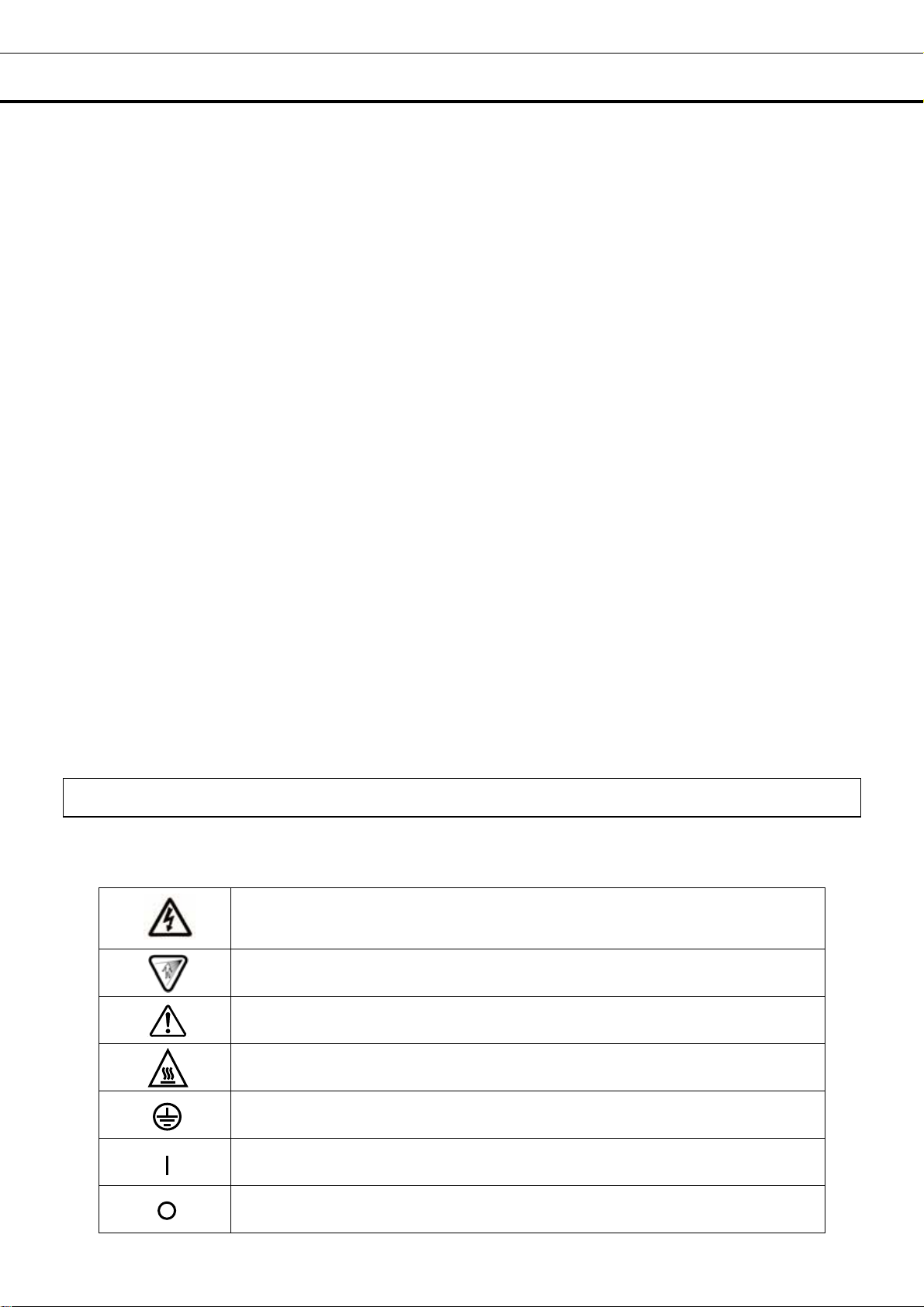
Labels on the unit
Some warning and/or caution labels are attached on the unit. Following shows the description of such
labels.
This label is on the cover in which the electrical components of high voltage are
enclosed to prevent the electric shock. The cover should be removed by a
qualified engineer or a service personnel only.
This symbol means UV caution.
This symbol means attention or refer to document.
This symbol means hot surface.
This symbol means earth.
This symbol means power switch “ON”.
This symbol means power switch “OFF”.
8
Page 10

CAUTIONS FOR USAGE
The cautions below are applicable when the model is MCO-18AIC(UV) or an optional UV system kit
MCO-18UVS2 is installed.
1. Always use humidifying pan and pan cover
The humidifying pan and pan cover prevent the UV light from escaping. Make sure they are installed
even if you do not need humidity.
2. Notice of recommended replacement of UV lamp
This unit is provided with a function to notify the recommendation of UV lamp replacement when the
accumulated ON time of UV lamp is over about 1,000 hours. The blink of the UV indicator on the control
panel recommends the replacement of UV lamp. For the replacement, contact Sanyo sales
representative or agent.
E18 will be displayed on the temperature indicator when the UV lamp is burned out. Contact Sanyo
sales representative or agent for the replacement.
3. Location of UV lamp
The UV lamp is located in the duct. Take care not to damage the lamp at the time of installation/removal
of attachments or humidifying pan.
9
Page 11
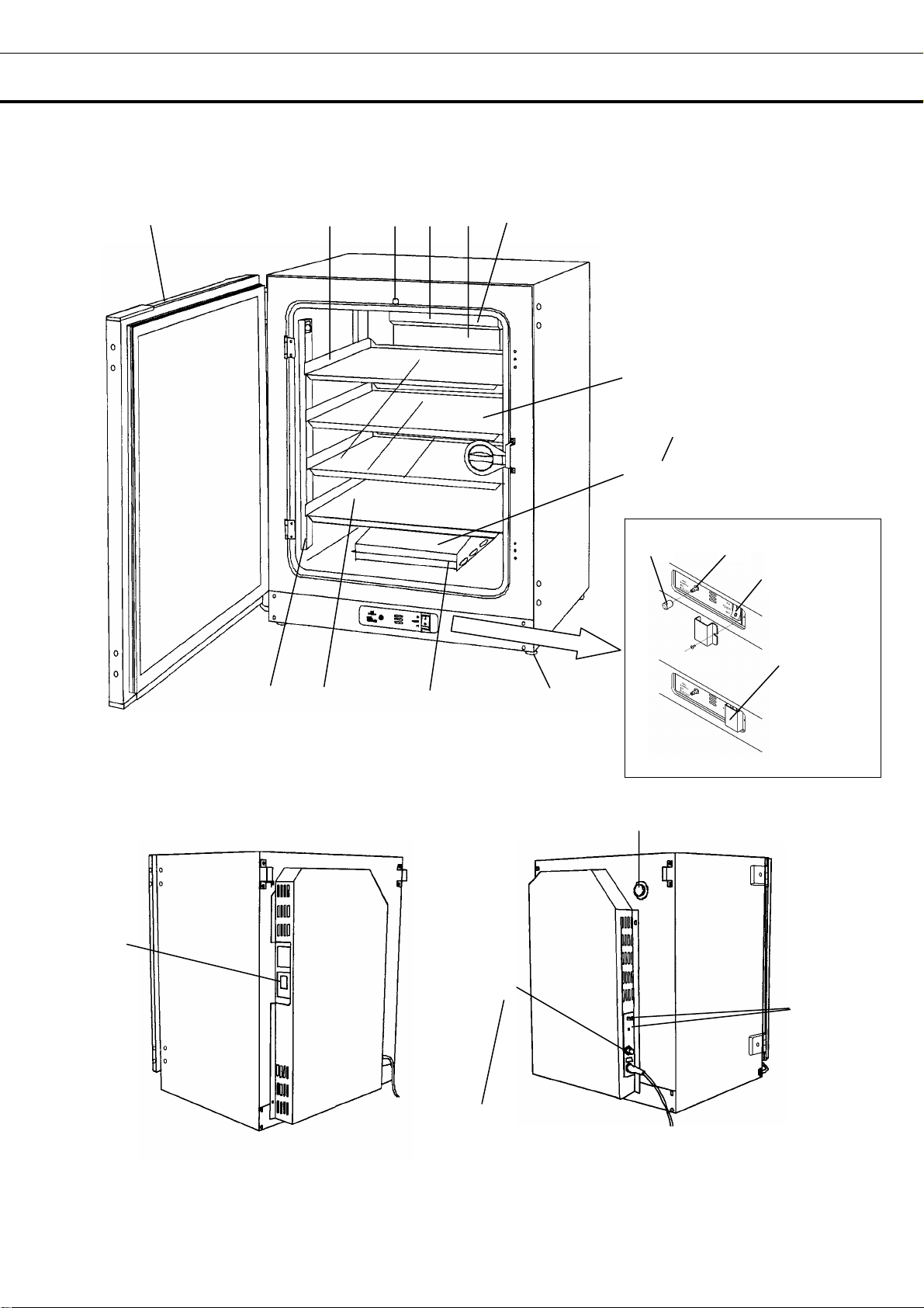
INCUBATOR COMPONENTS
17
1
5
6
7 8 9 (inside)12
14
20
MCO-18AIC(UV) or
When MCO-18UVS2is installed
34
2
MCO-18AIC(UV) or
when MCO-18UVS2is installed
13, 15, 16 (inside)
21
18
10
Rear left side Rear right side
19
Switch cover
11
10
Page 12

INCUBATOR COMPONENTS
1. Outer door: Sticks to frame with magnetic seal. Door heater is installed in the door panel. The
door opening is reversible. Contact Sanyo represent ative or agent to change the door hinge from left to
right or vice versa.
2. Inner door: Made of tempered glass, however avoid excessive impact on the glass.
3. Leveling foot: Screw type for adjusting the height. Adjust the foot so that the unit can be level.
4. Tray: Can be pulled toward you.
5. Tray support: Can be removed by lifting the front side and pulling toward you.
6. Side support: Right and left side supports can be removed for disinfection. See page 27 and 28.
7. Top duct: Inlet of circulating air. Removable.
8. Rear duct: Flow path for circulating air. Removable.
9. Fan (inside the rear duct): Made from polypropylene resin. Can be disinfected by an autoclave.
10. Sample air outlet: This also functions as an internal gas outlet. Normally, cover this outlet with
the sample air outlet cap.
11. Connecting port for CO
cylinder changeover accessory) is installed, both A and B are available. If MCO-21GC is not used, only
A is available. Refer to page 17 for gas cylinder connection. Ensure that the gas pressure is set at
0.03MPaG (0.3kgf/cm
12. Door switch: Detects the door opening/closing and stops the circulating fan and electromagnetic
valve for CO
when an optional UV system kit MCO-18UVS2 is installed).
13. Humidifying pan: Use sterile distilled water to fill the pan. Install the pan properly so that it can be
covered with the pan cover.
14. Humidifying pan cover: Prevents UV light being exposed to the chamber. When filling the pan,
lift the front side and take out the pan. See page 29 for details.
15. UV lamp (MCO-18AIC(UV) or when an optional UV system kit MCO-18UVS2 is installed):
Sanyo UV lamp does not generate ozone. Never look at the UV light directly. For replacement, contact
Sanyo representative or agent.
16. Water level sensor for humidifying pan: Detects the water level in the humidifying pan. See
page 23 for details.
17. Remote alarm terminal: Refer to page 13.
when door is open. UV lamp is also deactivated by door opening (MCO-18AIC(UV) or
2
2
G, 4.3psiG). Refer to page 18 for automatic cylinder changeover.
gas pipe (rear side): When an optional component MCO-21GC (gas
2
18. Access port: When not in use, cap with the rubber cap on both outside and inside.
19. Power switch: Main switch of the unit. Also functions as an over-current breaker. The switch is
covered by a switch cover to prevent the accidental push. To turn on or off the switch, remove the
switch cover by loosening the screw.
20. Glow starter (MCO-18AIC(UV) or when an optional UV system kit MCO-18UVS2 is installed):
For UV lamp (model; FG-7P)
21. Sample air outlet cap: Always attach this cap except at the time of using of sample air outlet.
11
Page 13

INCUBATOR COMPONENTS
Control panel and keypad
12 3
8 9
4
5
6
7
11
12
13
10
1. Digital temperature indicator (TEMPERATURE
o
C): Normally, this indicator shows the chamber
151617 14
temperature. In the setting mode, it shows the set value of the chamber temperature. If the self
diagnostic function detects any abnormality, an error code will be displayed.
2. Heater lamp (HEAT): This lamp lights when the heater is energized.
3. UV indicator (UV): This lamp lights when the UV lamp is ON. The blink of this indicator
recommends the replacement of UV lamp. See page 20 for the details.
4. Door lamp (DOOR): This lamp lights when the outer door is open.
5. Water level alarm lamp (RH PAN): This lamp flashes when the water in the humidifying pan is less
than approximately 1 liter.
6. Upper limit regulator: This regulator is used to set the upper temperature limit.
7. Over heat lamp (OVER HEAT): This lamp lights when the chamber temperature reaches the upper
limit set value.
8. CO
9. Digital CO
chamber. In the setting mode, it indicates the set value of the CO
inject lamp (INJECT): This lamp lights when CO2 gas is being injected.
2
density indicator (CO2 %): Normally, this indicator shows the CO2 concentration in the
2
concentration.
2
10. Set key (SET): Pressing this key to enter the setting mode, and the digits to be set will flash.
11. Calibration key (CAL): By pressing this key for approximately 5 seconds, the unit enters calibration
function mode. Also, used to change the UV lamp ON period. See page 30 and 21 for the details.
12. Alarm buzzer stop key (BUZZER): Press this key to silence the buzzer when the alarm operates
and the buzzer sounds.
13. CO
gas supply line indicator (A/B): The lamp for the supply line currently in use lights up
2
provided that MCO-21GC changeover accessory is installed.
14. CO
an automatic gas cylinder changeover MCO-21GC (option) is installed. When one CO
the CO
gas supply line switching key : This key to select CO2 gas supply line is available only when
2
cylinder is empty,
2
is supplied by the other cylinder automatically.
2
15. Enter key (ENT): Pressing this key memorizes the set value in the controller.
16. Numerical value shift key ( ): Pressing this key in the setting mode causes the numerical value
to shift. In key lock mode, pressing this key makes key lock ON or OFF.
17. Digit shift key ( ): Pressing this key in the setting mode causes the changeable digit to shift.
Pressing this key more than 5 seconds enters key lock mode. See page 22 for the key lock.
12
Page 14

INCUBATOR COMPONENTS
Remote alarm terminal
The remote alarm terminal is located at the rear right side.
The remote alarm terminal is a contact output.
Normal : OPEN
Abnormal : CLOSE
Contact capacity : DC 30V, 2A
Note:
• When the power switch is OFF or the power failure condition, the contact output is CLOSE.
• The remote alarm cannot be silenced by pressing the alarm buzzer stop key (BUZZER) since the
remote alarm is not conjunct with the BUZZER key
Remote alarm terminal
REMOTE ALARM
MAX DC30V 2A
Remote alarm terminal
N. O.
13
Page 15

INSTALLATION
Installation site
To operate this unit properly and to obtain maximum performance, install the unit in a location with the
following conditions:
Note: The ambient temperature must be at least 5oC lower than the set temperature.
1. A location not subjected to direct sunlight or direct air flow from an air conditioner
2. A location with clean air and adequate ventilation (Small and sealed room is not recommended.)
WARNING
If the unit is used in a small confined room, the CO2 density level in the air could rise and may be
harmful to humans.
Ventilate a room air occasionally when using CO
an enclosed small room and high level of gas density can be hazardous to health. In addition, avoid
inhaling the chamber air directly when opening the door if CO
3. A location away from heat generating sources
4. A location with a sturdy and level floor
gas for control. The gas density will increase in
2
gas is used.
2
WARNING
Install the unit on a sturdy floor. If the floor is not strong enough or the installation site is not
adequate, this may result in injury from the unit falling or tipping over.
Select a level and sturdy floor for installation. This precaution will prevent the unit from tipping.
Improper installation may result in water spillage or injury from the unit tipping over.
5. A location without flammable or corrosive gas
WARNING
Never install the unit in a flammable or volatile location. This may cause explosion or fire.
Never install the unit where acid or corrosive gases are present as current leakage or electric shock
may result due to corrosion.
6. A location not prone to high humidity
WARNING
Do not use the unit outdoors. Current leakage or electric shock may result if the unit is exposed to
rain water.
Never install the unit in a humid place or a place where it is likely to be splashed by water.
Deterioration of the insulation may result which could cause current leakage or electric shock.
14
Page 16

INSTALLATION
Prevent contamination
To prevent contamination of the chamber, select an appropriate location for installation as well as
ensuring the complete disinfection of the chamber components.
1. Avoid hot and humid location
Avoid location with high temperature and/or humidity as the presence of bacteria in the air is greater than
in the normal environment.
2. Avoid drafty location and location with many passers-by
Avoid locations near doors, air conditioners, fans, etc., where slight breezes can facilitate the entry of
bacteria into the chamber.
3. Installation in a sterile room
To promote efficient cultivation, it may be best to install the unit in a sterile room.
4. Use clean containers
Contamination is often caused by containers such as Petri dishes or bottles stored in the chamber
introducing contamination. Always keep the containers clean.
Installation
1. Remove the packaging materials and tapes
Remove all transportation packaging materials and tapes. Open the doors and ventilate the unit. If the
outside panels are dirty, clean them with a diluted neutral dishwashing detergent. (Undiluted detergent
can damage the plastic components. For the dilution, refer to the instruction of the detergent.) After
the cleaning with the diluted detergent, always wipe it off with a wet cloth. Then wipe off the panels with
a dry cloth.
2. Adjust the leveling feet
Extend the leveling feet by rotating them counterclockwise so they contact the floor or bench. Ensure
the unit is level.
3. Fix the unit
Two fixtures are attached to the rear of the frame. Fix the frame to the wall with these hooks and rope or
chain.
4. Ground (earth)
WARNING
Use a power supply outlet with ground (earth) to prevent electric shock. If the power supply outlet is
not grounded, it is necessary to install a ground by qualified engineers.
Never ground the unit through a gas pipe, water main, telephone line or lightning rod. Such
grounding may cause electric shock in the case of an incomplete circuit.
15
Page 17

BEFORE COMMENCING OPERATION
Sterilizing of chamber and attachments
Before first start-up of the unit, the chamber and internal attachments should be cleaned and sterilized as
follows.
Note:
Take care not to damage the UV lamp (MCO-18AIC(UV) or when an optional UV system kit
MCO-18UVS2 is installed) or water level sensor at the time of removal or replacement of attachments.
Do not clean the inside of the unit with a solution of disodium chlorate or other halogen-based solution
because this may cause corrosion of metal surfaces.
1. Take out all attachment such as trays, humidifying pans, etc, from the chamber. Refer to page 27 and
28.
2. Clean all of the attachments with neutral detergent and then wash out the detergent with distilled water.
3. Wipe the attachments with a gauze containing alcohol for sterilization and then wipe off with a dry
gauze.
4. Wipe the inside wall of the chamber with a gauze containing alcohol for sterilization and then wipe off
with a dry gauze.
5. Replace all attachments in the chamber.
Note:
Always insert the fan on the motor shaft surely. Improper insertion may cause poor performance.
6. Fill the humidifying pan with sterile distilled water.
16
Page 18

BEFORE COMMENCING OPERATION
Connection of CO2 gas cylinder
WARNING
Check the gas type and ensure that it is fit for the purpose. Make sure that all pipes are
connected correctly and are not liable to become disconnected. Ensure that the gas pressure is
set at the specified value. Improper connection of the gas pipe or use of incorrect gas pressure
may result in leakage of CO
lead to asphyxiation and risk of death.
Use a liquefied CO
gas cylinder, not a siphon (dip tube) type. The CO2 gas should be 99.5% or more
2
pure.
1. Install a pressure regulator (optional accessory MCO-100L) on the cylinder. Use a regulator rated at
25MPaG (250kgf/cm
2
G, 3600psiG) on the primary side and 0.2MPaG (2.0kgf/cm2G, 30psiG) on the
secondary side.
2. Using the gas supply pipe provided, connect the pressure regulator to the CO
left hand side of the CO
2
3. Set the CO
pressure on the secondary side to 0.03MPaG (0.3kgf/cm2G, 4.3psiG) (at gas injection).
2
Excessive pressure may cause disconnection of internal pipes inside the CO
in leakage of CO
gas into the atmosphere. Elevated level of CO2 gas can be hazardous to health
2
and may lead to asphyxiation and risk of death. The repair of the incubator will be necessary if the
internal pipe is disconnected.
4. Check that no gas is leaking at any point where the pipe connects with the CO
incubator.
Note:
• Refer to “Procedure for replacement of gas cylinder” enclosed with the unit at the time of replacement.
• The incubator, including the gas supply pipes and services must be examined at frequent intervals to
ensure they are safe. Ensure that items such as pipes are replaced if there is any sign of deterioration.
gas. Elevated level of CO2 gas can be hazardous to health and may
2
inlet located at the rear
2
incubator.
incubator which will result
2
regulator or the CO2
2
17
Page 19

BEFORE COMMENCING OPERATION
Automatic CO2 cylinder changeover
An automatic CO
kit switches the gas supply line when one CO
Note: The installation of MCO-21GC should be implemented by a qualified service personnel.
After attachment of MCO-21GC, do the following:
1. Connect a CO
on the left back of the unit. (See page 10 and 11.)
2. Connect a CO
for the connection of the gas cylinder.
3. Open the valve of each gas cylinder.
4. Check that the CO
5. Select a CO
6. When one cylinder is empty, the indicator is flashed, buzzer sounds (remote alarm is activated), and
“E01” is displayed alternately on the control panel while the gas supply line is switched to other one. To
silence the buzzer, press the BUZZER key.
7. Replace the empty CO
Note: Exercise caution when handling empty CO
cylinder.
This kit MCO-21GC detects that no more CO
chamber is not increased for a while after opening of CO
supply line. The switching of supply line can be caused by some other reasons; blocking or restricting of
gas tube, reduction of CO
in the cylinder. Therefore, always check the gas quantity in the cylinder prior to disconnection.
cylinder changeover system (MCO-21GC) is available as an optional accessory. This
2
gas cylinder is empty.
2
gas pipe to port A and B respectively. A connecting port for CO2 gas pipe is located
2
gas cylinder provided with a gas pressure regulator to each gas pipe. See page 17,
2
gas supply line indicator on the control panel is lit by pressing the switching key.
2
gas supply line (A or B).
2
gas cylinder.
2
gas cylinders as some gas can still be left in the
2
gas exists in a cylinder when the CO2 density in the
2
gas valve in the unit and switches the gas
2
gas pressure, or improper opening of CO2 gas cylinder, in spite of gas quantity
2
18
Page 20

OPERATING INSTRUCTIONS
Set of chamber temperature and CO2 density
Table below shows the basic procedure for setting the chamber temperature and CO
upper limit alarm temperature setting is also shown in the table. Perform key operations in the sequence
indicated in the table. The example in the table is based on the assumption that the desired temperature
o
is 37
C and CO2 density is 5%. Adjustment of the upper limit regulator should be executed after the
chamber temperature reaches the stable condition.
Note: The unit is set at the factory so that the chamber temperature is 37
Allow at least 4 hours until the next setting after setting of desired chamber temperature and setting CO
density to 0%, at the time of first start-up or start-up after no use for long term.
Basic operation sequence (Example: Chamber temperature; 37
Description of operation Key operated Indication after operation
1 Turn the power switch ON. ----
2 Press SET key. SET
By pressing digit shift key and
3
numerical value shift key, set the
figure to 37.0.
When pressed, the changeable digit is shifted.
4 Press ENT key. ENT
By pressing digit shift key and
5
numerical value shift key, set the
figure to 05.0.
When pressed, the changeable digit is shifted.
The current chamber temperature is displayed
in temperature indicator.
The left digit is flashed.
When pressed, the figure of settable digit
changes.
Set temperature is memorized.
Left digit in CO2 density indicator is flashed.
When pressed, the figure of settable digit
changes.
o
C and CO2 control is 0%.
o
C, CO2 density; 5%)
density. The
2
2
6 Press ENT key. ENT Set CO2 density is memorized.
(Executed after the chamber
temperature reaches the stable
condition)
7
Adjust upper limit regulator so that
the alarm temp. is 1
o
C higher than
In CO
In temperature indicator, upper limit temp. is
displayed. The upper limit temp. can be changed
by turning upper limit regulator.
density indicator, HI is displayed.
2
chamber temperature.
8 Press ENT key. ENT
This is the end of set mode and the indicators
display current temperature and CO
density.
2
Note:
• In each set mode, if the change of the setting is not necessary, pressing SET key skips to next set
mode.
• When the CO
density is set to 00.0, the control is OFF regardless of chamber density.
2
• The upper limit temperature set value will change when the regulator is turned even if the unit is not in
set mode, because the alarm circuit is an independent circuit.
• In each set mode, the indicator returns to the current temperature and CO
density display mode
2
automatically when 90 seconds has passed without any key operation.
19
Page 21

OPERATING INSTRUCTIONS
UV lamp
The clauses below are applicable when the model is MCO-18AIC(UV) or an optional UV system kit
MCO-18UVS2 is installed.
A UV lamp is located inside the rear duct to sterilize the water in the humidifying pan and air circulating in
the chamber.
Following shows precautions and instructions about the UV lamp.
• The UV light is exposed only to the inside of the duct and the humidifying pan cover when all chamber
components are installed properly.
• During cultivation, ensure all components are located adequately and never turn on the UV light without
the humidifying pan cover.
• Even if the unit is operating without turning on the UV lamp, the humidifying pan cover should be
installed properly. An operation without pan cover will affect the temperature distribution and humidify
recovery.
• Even if the unit is operated without humidifying, the humidifying pan and the pan cover should be
installed properly.
• When checking the UV lamp operation, open the outer door and push the door switch with the inner
door closed. The visible blue light can be checked under the humidifying pan cover. The UV light is
harmful to eyes. Never turn on the UV light with the inner door or humidifying pan cover opened.
• The UV lamp is ON for a predetermined period after the outer door is closed, or every 12 hours when
the outer door is not opened more than 12 hours continuously. The period of factory setting is 5 minutes.
The period can be changed when necessary as shown in the page 21.
• The recommended timing of lamp replacement (the ratio of UV output is less than 70% of initial value) is
when the accumulated ON time is over about 1,000 hours. The blink of the UV indicator when the UV
lamp is OFF means the accumulated time has exceeded about 1,000 hours and recommends the
replacement of the lamp. When replacing the UV lamp, contact Sanyo sales representative or agent.
• E18 is displayed on the temperature indicator when the UV lamp is burned out. In this case, replace
the lamp immediately. At the time of replacement, also replace the glow starter (Type; FG-7P). For the
replacement of UV lamp and glow starter, contact Sanyo sales representative or agent.
20
Page 22

OPERATING INSTRUCTIONS
Change of setting for UV lamp ON period
The clauses below are applicable when the model is MCO-18AIC(UV) or an optional UV system kit
MCO-18UVS2 is installed.
Follow the procedure below when changing the setting for UV lamp ON period.
Basic operation sequence (Example: change of UV lamp ON period from 5 minutes to 3 minutes)
Description of operation Key operated Indication after operation
1 Press CAL key for 5 seconds. CAL
By pressing digit shift key and
2
numerical value shift key, set the
figure to F01.
3 Press ENT key. ENT
By pressing digit shift key and
4
numerical value shift key, set the
figure to 003.
5 Press ENT key. ENT
• The available set range for the UV lamp is between 0 and 30 minutes (000 to 030). When set to 000,
the UV lamp is not turned on.
• The UV lamp is turned off during ON period when the outer door is opened. After closing the outer
door, the lamp turns on during predetermined period.
• Condensation will occur and/or temperature distribution may be affected due to the heat of the UV lamp
when the setting of the lamp operation is longer than 5 minutes or if only the outer door is opened
repeatedly.
• For the replacement of UV lamp, contact Sanyo sales representative or gent.
Pressing CAL key for about 5 seconds leads the calibration mode. In the calibration mode, the
calibration of temperature and CO
performance. Never touch any other keys on the control panel in the event of pressing CAL key
accidentally. After about 90 seconds, the unit returns to chamber temperature display mode
automatically.
When pressed, the changeable digit is shifted.
When pressed, the figure of settable digit
When pressed, the changeable digit is shifted.
When pressed, the figure of settable digit
density is possible. Wrong key operation affects the basic
2
The left digit in the temperature
indicator is flashed.
changes.
The current setting is displayed
in the CO
changes.
Set value is memorized and the display return to
normal display mode.
2
density indicator.
21
Page 23

OPERATING INSTRUCTIONS
Key lock function
This unit is provided with a key lock function. When the key lock is ON, change of temperature or CO
density setting through the key pad is not available.
Note: The key lock is set in OFF mode (L0) at the factory.
Display Mode Function
Key lock is OFF Enable to change of temperature and CO2 setting
Key lock is ON Disable to change of temperature or CO2setting
Procedure for key lock setting (change from key lock OFF to key lock ON)
Description of operation Key operated Indication after operation
1 ---- The current chamber temperature and
2 Press digit shift key for 5 seconds.
Press numerical value shift key
3
and scroll the figure to 1.
4 Press ENT key. ENT
Note:
• The key lock function is available for temperature and CO
• To cancel the key lock, set to L0 in the above procedure.
CO
density are displayed.
2
L0 is displayed in the temperature
indicator.
When pressed, the figure of settable
digit changes.
The key lock is set to ON.
The current chamber temperature is displayed.
density setting.
2
2
22
Page 24

OPERATING INSTRUCTIONS
Water level sensor
This unit is provided with a water level sensor for the humidifying pan. The sensor is set in active
position with respect to the installation of the humidifying pan. Take care not to damage the sensor at
the time of removal or installation of the humidifying pan.
When the humidifying pan is removed (side view)
When the humidifying pan is installed (side view)
Note: At the installation, check the humidifying pan is located far depth and the sensor is down.
Note:
• Lift the sensor before installing the humidifying pan if the sensor is in lower position after maintenance.
• At the time of installation of humidifying pan, check that the pan is set properly and sensor is down in
the pan. The water level alarm lamp (RH PAN) blinks if the sensor is not down completely. In this case,
set the pan again in adequate location.
• Use an alcohol for sterilization when cleaning the sensor, taking care not to stress the lead wire.
• The sensor detects the water level every 30 minutes. In addition, detection is executed after operation of
the outer door. It takes several seconds to detect the water level. Therefore, the water level alarm
lamp may flash a few times after the outer door is closed with the humidifying pan filled sufficiently.
Pan
Pan
Sensor
Sensor
23
Page 25

ALARMS & SAFETY FUNCTIONS
This unit has the alarms and safety functions shown in table below, and also self diagnostic functions.
Alarms and safety functions
Alarm & Safety Situation Indication Buzzer Safety operation
Upper limit
temperature alarm
Automatic set
temperature alarm
Automatic set CO
density alarm
Auto-return
Key lock When the key lock is “ON”. ----- ----- The setting is disabled.
Automatic calibration
function
CO2 gas cylinder
empty
Gas line changeover
Chamber
temperature sensor
abnormality
Sensor box
temperature sensor
abnormality
Ambient temperature
sensor abnormality
CO2 sensor
abnormality
Main heater
abnormality
Bottom heater
abnormality
Door heater
abnormality
Sensor box heater
abnormality
Disconnection of
sensor for each
heater
Air pump (for sample
air or auto-zero)
failure
Low humidifying
water
UV lamp failure
Recommendation of
new UV lamp
If the chamber temperature exceeds
the upper limit alarm temperature set
value.
If the chamber temperature deviates
from the set temperature by ±1
more.
If the chamber CO2 density deviates
2
from the set value by ±1% or more.
When there is no key pressing in
each setting mode for 90 seconds.
Normally, the zero point of the CO
sensor is calibrated every 4 hours (or
very 10 minutes for the first hour after
switch ON), using the atmosphere as
the gas to be calibrated.
If the CO2 density does not increase
when the gas valve is opened.
When the gas supply line is switched.
(only when MCO-21GC is installed)
If the temperature sensor is
disconnected.
If the temperature sensor is short
circuited.
If the sensor box temperature sensor is
disconnected.
If the sensor box temperature sensor is
short circuited.
If the ambient temperature sensor is
disconnected.
If the ambient temperature sensor is
short circuited.
If the output voltage of the CO2 sensor
is abnormal.
If the upper limit alarm temperature
alarm operates, or if the main heater is
open circuit, or the main heater relay
short circuit.
If the bottom heater goes open circuit,
or the bottom heater relay short circuit.
If the door heater goes open circuit,
or the door heater relay short circuit.
If the sensor box heater goes open
circuit, or the sensor box relay short
circuit.
If the relay of main heater, bottom
heater or sensor box heater goes open
circuit.
If the air pump (sampling or auto zero)
does not operate, or if there is
something wrong in the gas piping.
If the water in the pan is about 1 liter. RH PAN lamp blinks. ----- ----[MCO-18AIC(UV) or when
MCO-18UVS2 is installed]
When the UV lamp is burned out.
[MCO-18AIC(UV) or When
MCO-18UVS2 is installed]
The accumulated ON time is over about
1,000 hrs.
o
C or
• The alarm can be canceled by pressing the BUZZER key, but the remote alarm cannot be silenced. And the upper
limit temperature alarm cannot be silenced with the BUZZER key.
• E01 is cleared automatically when the gas is connected correctly and the buzzer is silenced with the BUZZER key.
When MCO-21GC is installed, press BUZZER key to silence the alarm after changeover of gas supply line.
• If one of E05 to E17 (except for E12, E13, and E14) is displayed, consult with a Sanyo sales representative or
agent.
Over heat lamp lights.
E12 or E16 and chamber
temperature are displayed
alternately.
All digits on the
temperature indicator blink.
All digits on the CO
density indicator blink.
Normal display mode. -----
2
The decimal point (period)
on the CO
indicator blinks.
E01 is displayed alternately
with the temperature on the
temperature indicator.
E01 is displayed alternately
with the temperature on the
temperature indicator.
Gas supply line indicator
blinks.
E05 is displayed alternately
with the temperature on the
temperature indicator.
E06 is displayed alternately
with the temperature on the
temperature indicator.
E07 is displayed alternately
with the temperature on the
temperature indicator.
E08 is displayed alternately
with the temperature on the
temperature indicator.
E09 is displayed alternately
with the temperature on the
temperature indicator.
E10 is displayed alternately
with the temperature on the
temperature indicator.
E11 is displayed alternately
with the temperature on the
temperature indicator.
E12 is displayed alternately
with the temperature on the
temperature indicator.
E13 is displayed alternately
with the temperature on the
temperature indicator.
E14 is displayed alternately
with the temperature on the
temperature indicator.
E15 is displayed alternately
with the temperature on the
temperature indicator.
E16 is displayed alternately
with the temperature on the
temperature indicator.
E17 is displayed alternately
with the temperature on the
temperature indicator.
E18 is displayed alternately
with the temperature on the
temperature indicator.
UV indicator blinks when
UV lamp is OFF.
2
2
density
Continuous tone
Intermittent tone with
15 minutes delay.
Intermittent tone with
15 minutes delay.
Intermittent tone Remote alarm
Intermittent tone
Intermittent tone
Intermittent tone
Intermittent tone Remote alarm
Intermittent tone
Intermittent tone Remote alarm
Intermittent tone Remote alarm
Intermittent tone Remote alarm
Intermittent tone Remote alarm
Intermittent tone Remote alarm
Intermittent tone
Intermittent tone Remote alarm
Heater OFF
Remote alarm
Remote alarm with 15
minutes delay
Remote alarm with 15
minutes delay
The setting mode is
canceled.
----- -----
Gas supply line is
altered.
Remote alarm
Heater OFF
Remote alarm
valve close.
CO
2
Remote alarm
CO2 valve close.
Remote alarm
CO
valve close.
2
Remote alarm
----- -----
24
Page 26

SETTING OF ALARM RESUME TIME
The alarm buzzer is silenced by pressing BUZZER key on the control panel during alarm condition.
The buzzer will be activated again after certain suspension if the alarm condition is continued. The
suspension time can be set by following the procedure shown in the table below.
The example in the table is based on the assumption that the desired duration is 20 minutes.
Note: The duration is set in 30 minutes at the factory.
Table Changing procedure for alarm resume time (Ex: change from 30 minutes to 20 minutes)
Description of operation Key operated Indication after operation
1 ----
2 Press CAL key for 5 seconds.
3
Set the figure to F25 with the digit
shift key and numerical value shift
CAL
When pressed, the figure of settable
key.
4 Press ENT key. ENT
Set the figure to 020 with the
5
numerical value shift key.
6 Press ENT key. ENT
• The settable alarm resume time are 0, 10, 20, 30, 40, 50, or 60 minutes (The setting is 000, 010, 020,
030, 040, or 060 respectively). The buzzer would not reset if the reset time is set in 000.
• The set mode returns to the temperature display mode automatically when 90 seconds has passed
without any key operation. In this case, any setting before pressing ENT key is not memorized.
The current chamber temperature is
displayed.
The left digit is flashed.
The settable digit is shifted.
digit changes.
The current setting is displayed.
The middle digit is flashed.
When pressed, the figure of settable
digit changes.
The setting is memorized and
the current chamber temperature is
displayed.
25
Page 27

ROUTINE MAINTENANCE
WARNING
Always disconnect the power supply to the unit prior to any repair or maintenance of the unit in
order to prevent electric shock or injury.
Ensure you do not inhale or consume medication or aerosols from around the unit at the time of
maintenance. These may be harmful to your health.
CAUTION
Always put on dry gloves to protect hands at the time of maintenance. Failure to use gloves may
result in cuts or abrasions from any sharp edges or corners.
Sterilizing of chamber and attachments
When the chamber of the unit is contaminated, the chamber and internal attachments should be cleaned
and sterilized as follows.
Note:
Take care not to damage the UV lamp or water level sensor at the time of removal or replacement of
attachments.
Do not clean the inside of the unit with a solution of disodium chlorate or other halogen-based solution
because this may cause rust.
1. Take out all trays and the humidifying pan from the chamber.
2. Remove ducts, side support (right and left side), tray supports, and the fan as shown in the figures on
page 27 and 28.
3. Clean all the attachments with neutral detergent and then rinse away the detergent with distilled water.
4. Wipe the attachments with a gauze containing alcohol for sterilization and then wipe off with a dry
gauze.
5. Wipe the inside wall of the chamber with a gauze containing alcohol for sterilization and then wipe off
with a dry gauze.
6. Replace all attachments in the chamber.
Note:
Always insert the fan on the motor shaft surely. Improper insertion may cause poor performance.
7. Fill the humidifying pan with sterile distilled water.
26
Page 28

ROUTINE MAINTENANCE
Removal of attachments
Note:
Take care not to damage the UV lamp (MCO-18AIC(UV) or when an optional UV system kit
MCO-18UVS2 is installed) or water level sensor at the time of removal or replacement of attachments.
1. Close the valve of the gas cylinder and turn off the power.
2. Open the outer door. Remove 2 pins fixing the inner hinge and remove the inner door.
3. Pull out the all trays. See Fig. 1
4. Remove all tray supports on the right and left side by lifting up the front side. See Fig. 2.
5. By lifting up the humidifying pan cover, unhook it at the rear and remove the cover as shown in Fig. 3.
6. Take out the humidifying pan. See Fig. 4
7. After removing 2 screws fixing the top duct, take out the top duct by removing pin. See Fig. 5.
8. To remove the rear duct, lift it up as shown in Fig. 6.
Fig. 1
Fig. 4 Fig. 5 Fig. 6
Fig. 2 Fig. 3
27
Page 29

ROUTINE MAINTENANCE
9. To removing the circulating fan, pull out the spring and then pull the fan. See Fig. 7.
10. Loosen and remove the screw fixing the clamp and remove the clamp. See Fig. 8 and Fig. 9.
11. By lifting the side support, take it off from the hooks. See Fig. 10.
12. Replace all attachments in the chamber with the reversed order mentioned above.
Note:
• Always insert the fan on the motor shaft surely.
Check that the fan does not hit the rear panel by
turning the fan manually. Improper insertion may
cause poor performance.
• As shown in the figure, set the shelf with the edge
bent downwardly positioned at the front. Improper
setting cause tilted or unstable condition.
Fig. 7
Fig. 9
Downwardbend
Fig. 8
Fig. 10
28
Page 30

ROUTINE MAINTENANCE
Filling the humidifying pan
To fill the humidifying pan or to replace the water in the humidifying pan, do the following:
1. Lift the front side of the humidifying pan cover as
shown in Fig. 1.
2. Pull out the humidifying pan toward you. See Fig.
2.
3. Dispose of the water in the pan and wash it with
neutral detergent. Then rinse the pan with distilled
water sufficiently. Finally, wipe the pan with a soft
cloth and alcohol for disinfection.
4. Wipe off the bottom of the chamber completely.
5. Place the pan under the pan cover and pour the
sterile distilled water (about 3 liters) into it. See Fig.
3. Make sure that the water is pre-heated at 37
6. Push the pan into its correct position and replace
the cover over the pan. Close the inner and outer
door.
7. Check that the water level alarm lamp on the
control panel is off.
Note:
• The sterile water filled in the humidifying pan
should be pre-heated at 37
the chamber temperature.
• Replace the water in the pan by the above
procedure when the water level alarm lamp blinks.
o
C. Cold water lowers
o
C.
Fig. 1
Fig. 2
Fig. 3
29
Page 31

CALIBRATION
Temperature calibration
1. Press the CAL key for approximately 5 seconds.
2. The third digit of the temperature indicator flashes, and the CO
3. Set the present correct temperature with the key and key, then press the ENT key.
4. The unit automatically reverts to the display mode.
[Example]
If the displayed chamber temperature is 37.0
1. Press the CAL key for about 5 seconds.
2. The “3” on the temperature indicator flashes, and the CO
3. Adjust the set value to the actual value of 36.8
4. The unit automatically reverts to the display mode.
Note:
It is important to accurately measure the temperature inside the unit when performing temperature
calibration. Particularly, the temperature gauge used must have an accuracy of 0.5 Class or better.
The temperature must be measured at several points.
The temperature setting must not change by more than ±1.0
error tone is emitted, the input data is ignored, and the unit reverts to the display mode. Consequently, if
it is necessary to change the temperature by more than 1.0
a period of time.
density indicator goes out.
2
o
C (set value) and the actual temperature is 36.8oC.
density indicator goes out.
o
C with the key and key, then press ENT key.
2
o
C during calibration. If it exceeds this, an
o
C, perform calibration in several stages over
CO2 calibration
Span setting
Span setting should be done under stable condition of temperature, humidity, and CO
1. Press the CAL key for about 5 seconds.
2. The third digit on the temperature indicator flashes, and the CO
3. Press the CAL key once again.
4. The third digit on the CO
5. Set the present correct CO
density indicator flashes, and the temperature indicator goes out.
2
density with the key and key, then press the ENT key.
2
6. The unit automatically reverts to the display mode.
Note:
This calibration is available when the setting of CO
density is 2% or more.
2
[Example]
For an internal CO
density of 5.0% (setting) and a measured value of 4.5%.
2
1. Press the CAL key for about 5 seconds.
2. The third digit on the temperature indicator flashes, and the CO
3. Press the CAL key once again.
4. The third digit on the CO
5. Set the present correct CO
density indicator flashes, and the temperature indicator goes out.
2
density (4.5%) with the key and key, then press the ENT key.
2
6. The unit automatically reverts to the display mode.
density indicator goes out.
2
density indicator goes out.
2
density.
2
30
Page 32

TROUBLESHOOTING
If the unit malfunctions, check out the following before calling for service.
The unit does not operate at all
• The unit is not plugged correctly into a power outlet.
• The circuit breaker at the power source is active or a power failure has occurred.
The key operation is disabled
• The key lock function is set in ON mode.
If the alarm function operates
[At the beginning of operation]
• The chamber temperature is not equal to the set value.
• The chamber CO
a. The secondary pressure of the pressure regulator is not equal to the set value (0.03MPaG,
0.3kgf/cm
b. The tube is not connected securely between the pressure regulator and the unit.
[During operation]
• The upper limit alarm temperature is not set at least 1
• The set temperature value was changed, or the door was left open for a long period. Or a low
temperature load was placed inside the unit. In this case, if the unit is left as it is, the alarm will
eventually clear itself.
• The gas tube has slipped off or the gas leaks.
• The set value of the gas density was changed.
• The gas cylinder is empty. Check the primary pressure of the CO
primary pressure of less than 3.8MPaG (38kgf/cm
cylinder soon.
If the chamber temperature is not equal to the set temperature
• The ambient temperature must always be at least 5
• The outer door was closed while the inner door was left open.
If the gas density does not coincide with the set value
• The secondary pressure is not set to 0.03MPaG (0.3kgf/cm
• The gas tube is clogged or chinked.
If the chamber humidity does not rise
• The humidifying pan is not filled with sterile distilled water. (Always use sterile distilled water.)
If the CO
consumption is too much
2
• The door is opened frequently.
• There is any gas leakage at the connection or pin hole on the tube. It is recommended to replace the
tube once a year.
• The gasket of the inner door is not completely sealed.
• The access port at the upper left corner is opened.
If normal cultivation cannot be done and chamber gas density is suspect
• The environment around the unit is not normal. The source of the contaminated gas is nearby.
• The unit is installed in an enclosed space.
If it takes much time to recover the gas density
• HEPA filter is provided in the gas piping. If it takes much time to recover the gas density even though
the gas pressure is normal, it may be that dust on the HEPA filter prevents the gas flow. Consult the
Sanyo dealer or agent.
density is not equal to the set value.
2
2
G, 4.3psiG).
o
C higher than the set chamber temperature.
cylinder once a week. (The
2
G) means a little gas in the cylinder. Replace the
o
C less than the set temperature.
2
G, 4.3psiG).
2
31
Page 33

ENVIRONMENTAL CONDITIONS
This equipment is designed to be safe under the following conditions (based on the IEC 1010-1):
1. Indoor use;
2. Altitude up to 2000 m;
3. Ambient temperature 5
4. Maximum relative humidity 80% for temperature up to 31
humidity at 40
5. Mains supply voltage fluctuations not to exceed ±10% of the nominal voltage;
6. Other supply voltage fluctuations as stated by the manufacturer;
7. Transient overvoltages according to Installation Categories (Overvoltage Categories) II; For mains
supply the minimum and normal category is II;
8. Pollution degree 2 in accordance with IEC 664.
o
C;
o
C to 35oC
o
C decreasing linearly to 50% relative
DISPOSAL OF UNIT
WARNING
If the unit is to be stored unused in an unsupervised area for an extended period ensure that children
do not have access and doors cannot be closed completely.
The disposal of the unit should be undertaken by appropriate personnel. Always remove doors
to prevent accidents such as suffocation.
32
Page 34

STACKED MODULE
This unit can be stacked by using the stacking kit. Following shows the procedure for stacking the unit.
Consult with a Sanyo representative or agent prior to stacking procedure as such work involves dangers.
WARNING
Select a level and sturdy floor having enough strength for installation of stacked module.
Never stack 3 or more units.
Take care not to drop or tip over the unit when stacking as this can cause injury or damage of the
unit.
1. Turn off the power switch and disconnect a plug of each unit.
2. The stacking plate A and B are attached on the back of each unit. To prepare the stacking plate A
and B, remove the rear cover by unscrewing 6 screws on the rear cover. See the figure below.
3. Take out the stacking plate A and B by loosening 2 fixing screws on each unit.
4. Replace the rear cover and fix it with 6 screws.
5. Check that the lower unit is level.
Note:
When stacking the unit, 2 stacking plates A and 2 stacking plates B are necessary. Each unit has 1
stacking plate A and 1 stacking plate B attached to the back. Remove stacking plate A and B from back
of each unit.
Rear cover
Stacking plate A
Fixing screws
Stacking plate B
33
Page 35

STACKED MODULE
6. Apply the protective sticker enclosed with the unit at each corner on the top of the lower unit to avoid
scratches or damage.
7. Fix the stacking plate A at 2 locations on the top front of the lower unit by using 2 screws removed in
step 3.
8. Remove the front panel on the upper unit by unscrewing the 4 fixing screws and then disconnect the
wires and gas tube.
9. Stack the unit so that both units can be aligned straight. Also check the upper unit is level. If it is not
level, keep the unit even by adjusting the leveling legs.
10. Secure the upper unit with the stacking plate A and 2 screws removed in step 3.
11. Remove 2 hooks on the rear side of the lower unit by unscrewing each 2 fixing screws.
12. Remove 1 screw on the bottom right and left on the rear side of the upper unit.
13. Fix the stacking plate B at the right and left on the rear of the lower and upper unit with 3 screws
removed in step 11 and 12.
14. Replace the front panel on the upper unit after connecting the wires and gas tube.
15. Fix the stacked unit to the wall with 2 hooks on the rear of the upper unit and rope or chain.
Front panel
Stacking plate A
Protective sticker
Stacking plate B
Hook
34
Page 36

SPECIFICATIONS
Name CO2 Incubator
Model MCO-18AIC MCO-18AIC(UV)
External dimensions W620 x D710 x H900 (mm)
Internal dimensions W490 x D523x H665 (mm)
Interior volume 170 L
Exterior Painted steel
Interior Stainless steel containing copper
Outer door Painted steel
Inner door Tempered glass
Tray 4 trays made of stainless steel containing copper
Access port Inner diameter; 30 mm, On the back side
Insulation Rigid polyurethane foamed-in place (CFC-FREE)
Heating system DHA system (heater jacket + air jacket system)
Heater 314 W
Humidifying system Natural evaporation with humidifying pan
Temperature controller PID control system
Temperature display Digital display
CO2 controller PID control system
CO2 density display Digital display
Air circulation Fan assisted
Air filter
UV lamp
Water level sensor
Alarm
Remote alarm contact Allowable contact capacity: DC 30 V, 2 A
CO2 inlet connection 4 to 6 mm diameter tube
CO2 inlet pressure 0.03MPaG (0.3kgf/cm2G, 4.3psiG)
Accessories 4 trays, 4 sets of tray support, 1 gas tube, 1 humidifying pan,
Weight 93 kg
Optional accessory
Note: Design or specifications will be subject to change without notice.
The ballast is not user replaceable part. Please contact a qualified service personnel.
High/Low temperature alarm, CO
Stacking plate A and B (fixed on rear of the unit), 4 protective stickers, 2 tube bands
Automatic CO
Extra tray (MCO-46ST) including 2 tray supports, Half tray (MCO-25ST)
UV system kit (MCO-18UVS2), Roller base (MCO-18RB)
W450 x D450 x H12 (mm), Maximum load; 7 kg/tray
0.3μm, Efficiency; 99.97% or more
----- 4W X 1 (ozone-free emission)
Optical type
density alarm, Upper limit temperature alarm
2
Door alarm, UV lamp failure alarm
cylinder regulator (MCO-100L)
CO
2
cylinder changeover system (MCO-21GC)
2
UV lamp replacement kit (MCO-20UV)
35
Page 37

PERFORMANCE
Temperature control range
Temperature distribution
Temperature variation
Ambient temperature +5
o
± 0.25
C* (ambient temperature; 25oC, setting; 37oC, 5%, no load)
o
± 0.1
C (ambient temperature; 25oC, setting; 37oC, 5%, no load)
CO2 control range
CO2 variation
± 0.15% (ambient temperature; 25
Chamber humidity
Maximum heat emission
Temperature; 5
Usable environment condition
(The designed performance may not be obtained when
the ambient temperature is equal or less than 15
Maximum power consumption
Total maximum
current
350 W 310 W
110 to 120 V, 60 Hz 220 V, 60 Hz 220 to 240 V, 50 Hz
2.8 A 1.4 A 1.4 A
Note: The unit with CE mark complies with EC directives 89/336/EEC, 93/68/EEC and 73/23/EEC.
* It is based on our measuring method.
o
C to 50oC (ambient temperature; 5oC to 35oC)
0 to 20%
o
C, setting; 37oC, 5%, no load)
95 ± 5% R.H.
1120 kJ/h
o
C to 35oC, Humidity; equal or less than 80% R.H.
o
C)
36
Page 38

CAUTION
Please fill in this form before servicing.
Hand over this form to the service engineer to keep for his and your
safety.
Safety check sheet
1. Incubator contents :
Risk of infection:
Risk of toxicity:
Risk from radioactive sources:
(List all potentially hazardous materials that have been stored in this unit.)
Notes :
2.
Contamination of the unit
Unit interior
No contamination
Decontaminated
Contaminated
Others:
3. Instructions for safe repair/maintenance of the unit
a) The unit is safe to work on
b) There is some danger (see below)
Procedure to be adhered to in order to reduce safety risk indicated in b) below.
Date :
Signature :
Address, Division :
Telephone :
□Yes □No
□Yes □No
□Yes □No
□Yes □No
□Yes □No
□Yes □No
□Yes □No
□Yes □No
□Yes □No
□Yes □No
Product name :
CO
incubator
2
Please decontaminate the unit yourself before calling the service engineer.
Model :
MCO-18AIC
MCO-18AIC(UV)
Serial number : Date of Installation :
37
Page 39

(
7FB6P101338005
18 May 2005)
Recycled paper
CEM
SANYO Electric Biomedical Co., Ltd.
10-15 Hongo 3-Chome
Bunkyoku, Tokyo 113-8434 Japan
Printed in Japan
 Loading...