

Page 1
FILE NO.
Service Manual
CD Portable Radio
Cassette Recorder
CONTENTS
Laser beam safety precaution..........................................1
Wiring Connection...........................................................2
Tuner Adjustments ........................................................... 3
Exploded View (Cabinet & Chassis) ................................5
Parts List .......................................................................... 6
IC Block Diagram & Description.......................................8
Wiring Diagram (BATTERY, CD SW, CASS).................13
Schematic Diagram (Main) .............................................. 14
Schematic Diagram (CD MAIN) ....................................... 16
Wiring Diagram (CD MAIN)............................................18
Wiring Diagram (DISPLAY)............................................Rear
MCD-S935F (AU)
(XE)
PRODUCT CODE No.
164 126 01 XE
164 126 02 AU
REFERENCE No. SM5810655
Page 2
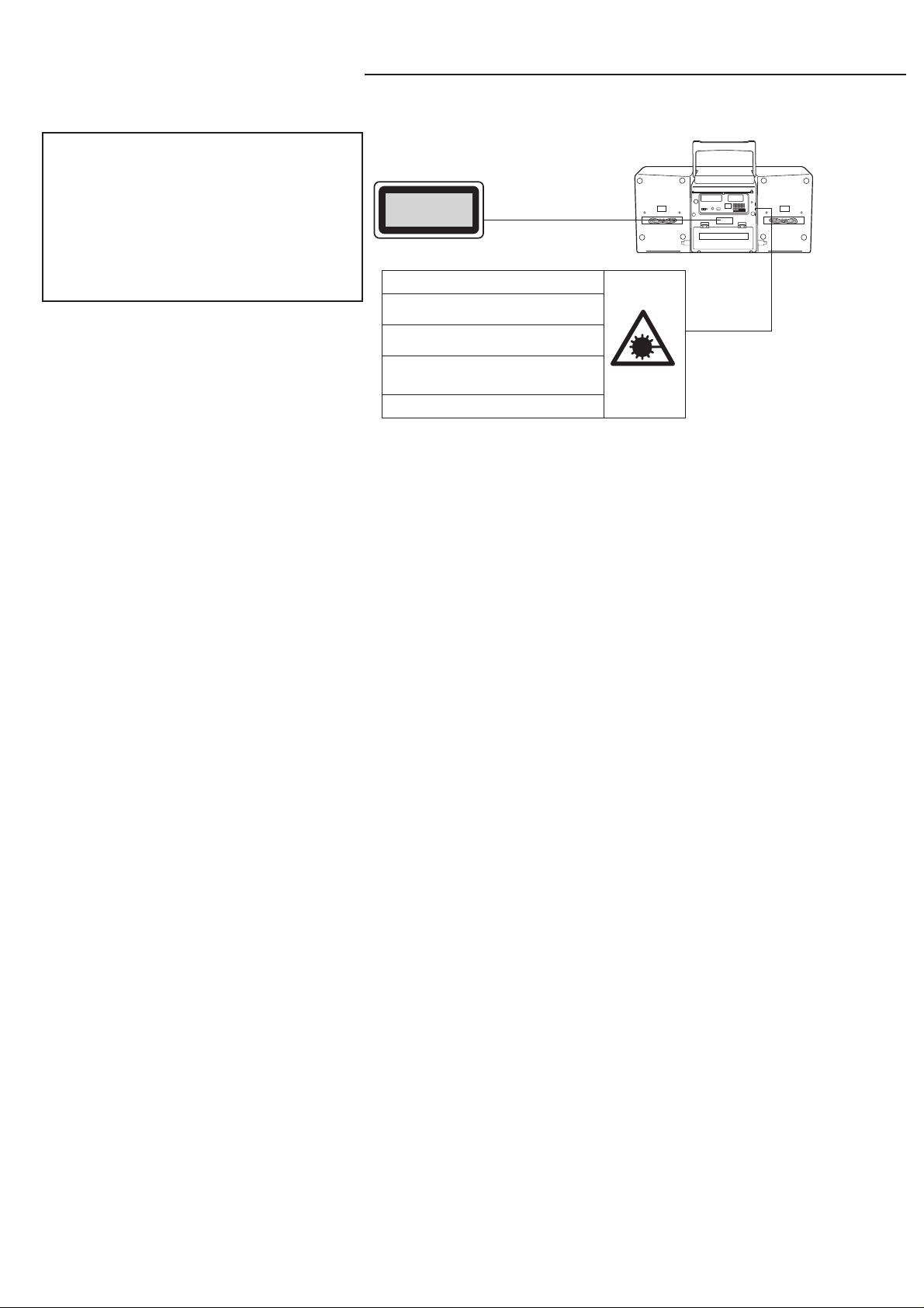
LASER BEAM SAFETY PRECAUTION
• Pick-up that emits a laser beam is used in this CD player section.
CAUTION :
USE OF CONTROLS OR ADJUSTMENTS
OR PERFORMANCE OF PROCEDURES
OTHER THAN THOSE SPECIFIED HEREIN
MAY RESULT IN HAZARDOUS RADIATION
EXPOSURE
CLASS 1 LASER PRODUCT
LUOKAN 1 LASERLAITE
KLASS 1 LASERAPPARAT
LASER OUTPUT..........0.6 mW Max. (CW)
WAVELENGTH ............. 790 nm
CAUTION-INVISIBLE LASER RADIATION WHEN OPEN AND
INTERLOCKS DEFEATED. AVOID EXPOSURE TO BEAM.
ADVARSEL-USYNLIG LASER STRÅLING VED ÅBNING, NÅR
SIKKERHEDSAFBRYDERE ER UDE AF FUNKTION, UNDGÅ
UDS ÆTTELSE FOR STRÅLING.
VARNING-OSYNLIG LASER STRÅLNING NÄR DENNA DEL
ÄR ÖPPNAD OCH SPÄRR ÄR URKOPPLAD. STRÅLEN ÄR
FARLIG.
VORSICHT! -UNSICHTBARE LASERSTRAHLUNG TRITT
AUS, WENN DECKEL GEÖFFNET UND ENN
SICHERHEITSVERRIEGELUNG ÜBERBRÜCKT IST. NICHT,
DEM STRAHL AUSSETZEN.
VARO !-Avattaessa ja suojalukitus ohitettaessa olet alttiina
näkymättömälle lasersäteilylle. Älä katso säteeseen.
- 1 -
Page 3
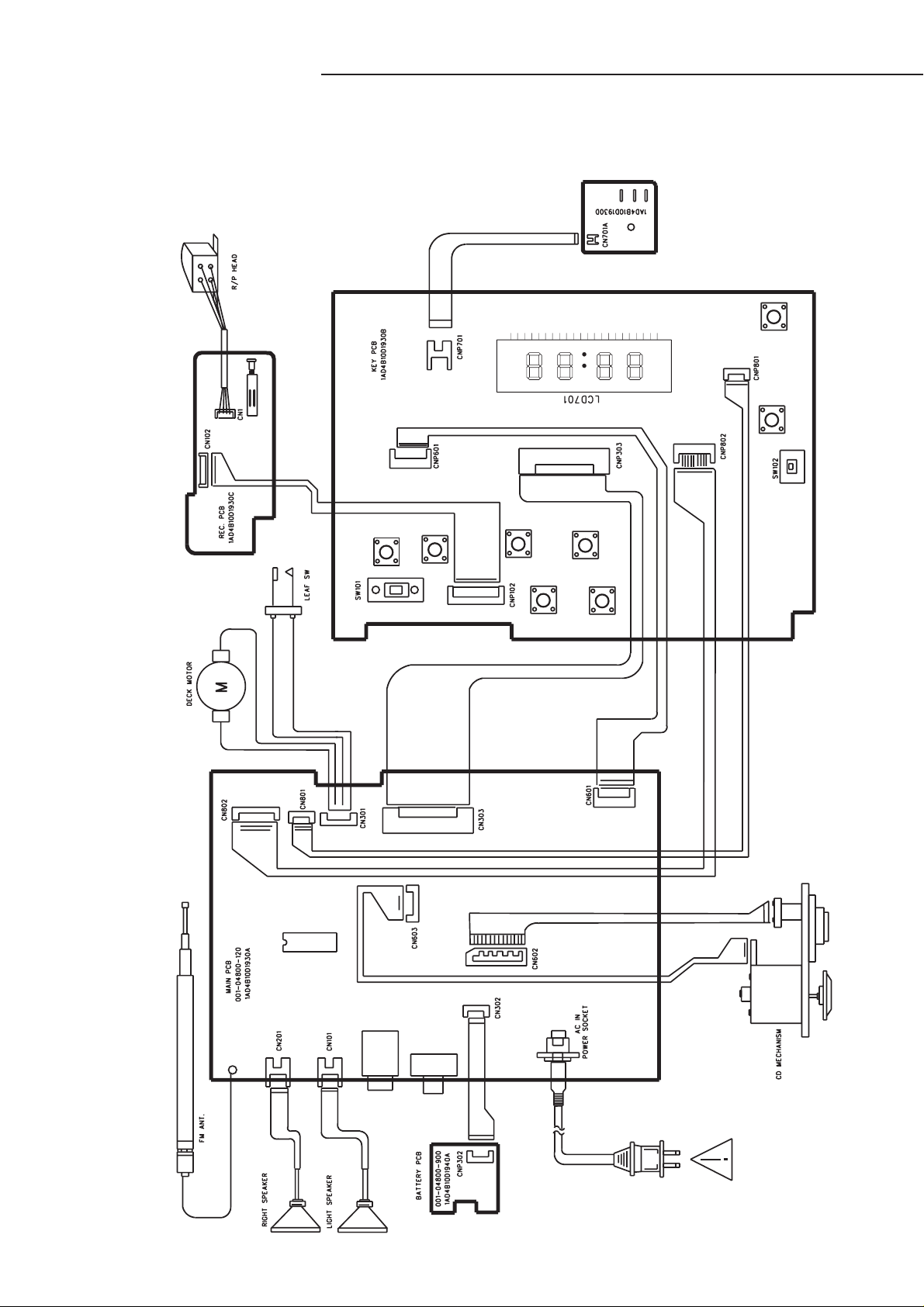
WIRING CONNECTION
This is a basic wiring connection .
- 2 -
Page 4
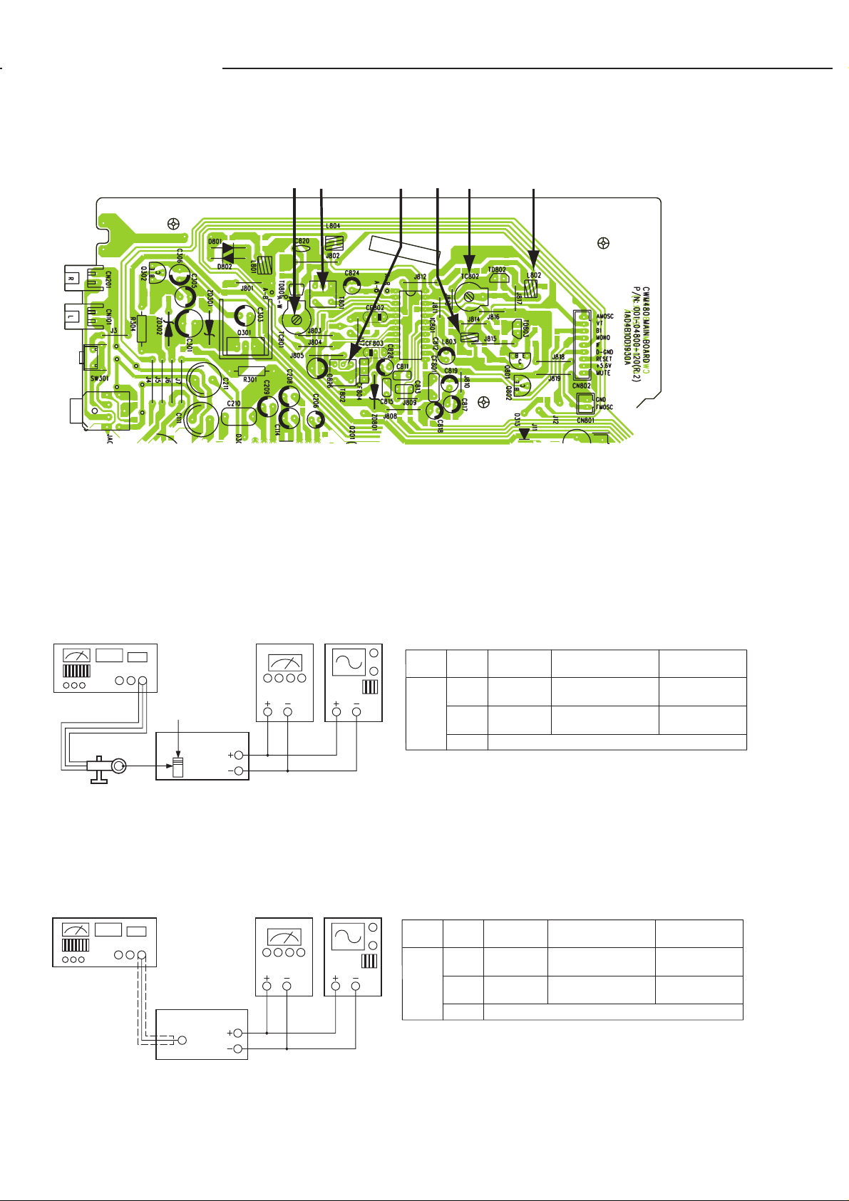
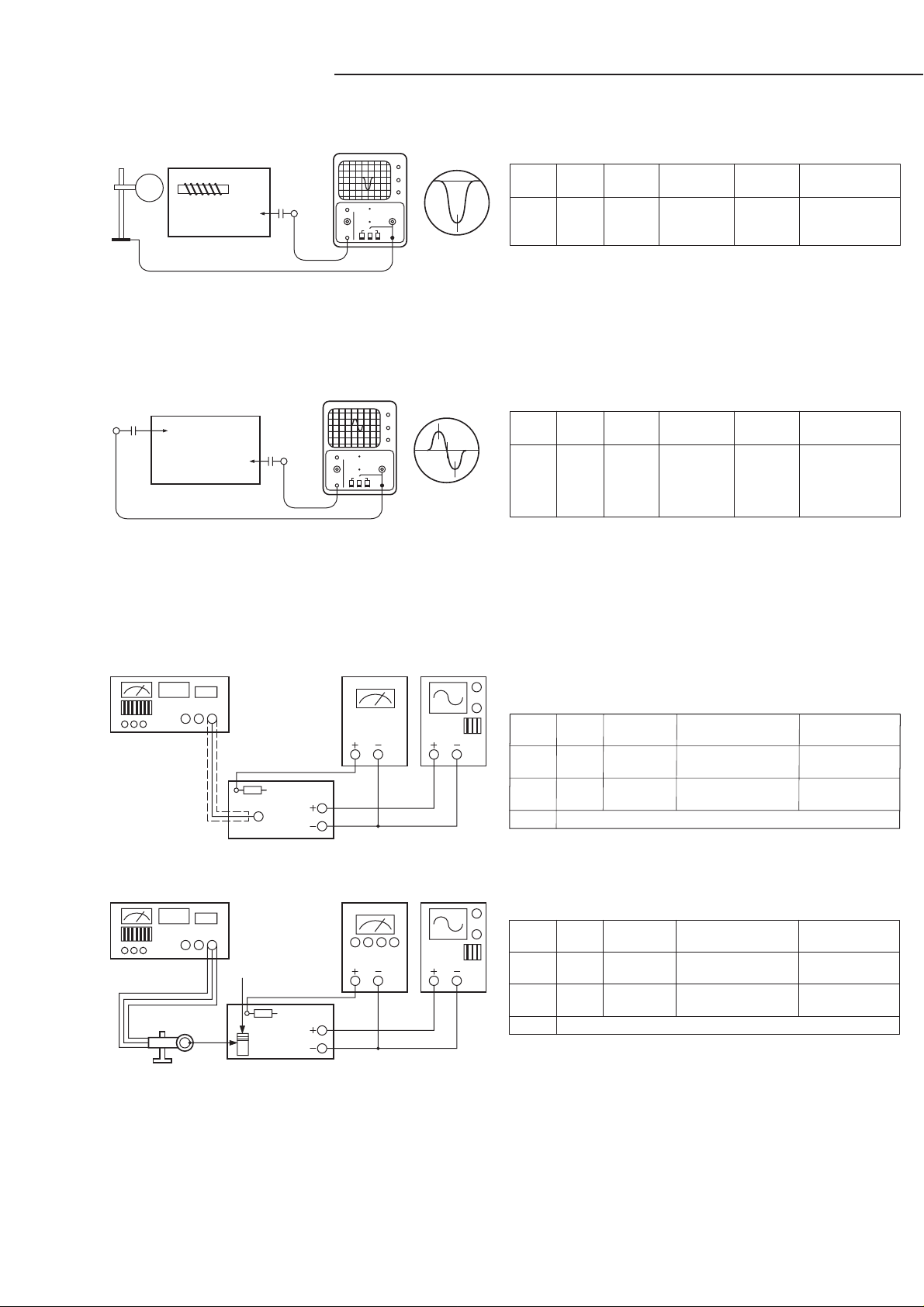
TUNER ADJUSTMENTS
Part Location
TC801 T801 T802 L803 TC802 L802
(1). AM TRACKING ADJUSTMENT
Signal Generator ...... Connects to the AM ANT. Coil througt the loop antenna.
Adjust for the indication of VTVM of the wave form scope to be maximum.
AM-SG
AC EVM
OUT
AM LOOP ANT
60cm
(FIG.4)
OSCILLOSCOPE
(USA)
BANDAMSTEP
1
2
3
SING.
FRE.
600KHz
1400KHz
REPEAT STEP 4 AND 5 SEVERAL TIMES
ADJUST FOR
MAXIMUM
SENSITIVITY
MAXIMUM
SENSITIVITY
(2). FM RF TRACKING ADJUSTMENT
Signal Generator ...... Connects to the FM ANT JACK (FM IN) through the dummy.
FM-SG
75 OHM
FM ANT
AC EVM
OUTPUT
OSCILLOSCOPE
BANDFMSTEP
1
2
3
SING.
FRE.
90MHz
106MHz
REPEAT STEP 1 AND 2 SEVERAL TIMES
ADJUST FOR
MAXIMUM
SENSITIVITY
MAXIMUM
SENSITIVITY
ADJUSTMENT
L805
(ANT COIL)
TC801
ADJUSTMENT
L802
TC802
(FIG.5)
- 3 -
Page 5
TUNER ADJUSTMENTS
(3). AM IF ADJUSTMENT
AM LOOP ANT
IC301
18PIN
(4). FM IF ADJUSTMENT
0.1U
(FIG.1)
450 KHz
BAND
MW-IF
STEP1SING.
FRE.
450KHz
RADIO
SETTING
ADJUST-
MENT
T802
REMARKS
ADJUST FOR
BEST IF WAVE
FORM
300PF
0.1U
(FIG.2)
10.5MHz
10.7
10.9
WAVE FORM
(MHZ)
(5). TUNING FREQUENCY RANGE ADJUSTMENT
FM-SG
75 OHM
FM BAND
CD
VOLTAGE
METER
R803
OUTPUT
FM ANT
OSCILLOSCOPE
BAND
FM-IF
STEP1SING.
FRE.
10.7MHz
RADIO
SETTING
ADJUST-
MENT
- - - -
(USA)
FM Band: Set the internal modulation of Singnal
generator to 1 KHz Dev. 22.5KHz
NO.
BAND
SING.
ADJUST FOR
FRE.
FM
87.5MHz
1
CHECK
1.4V~1.5V
FM
107.9MHz
2
CHECK
5.0V~5.5V
3
REPEAT STEP 1 AND 2 SEVERAL TIMES
REMARKS
- - - -
ADJUSTMENT
L803
- - - -
AM-SG
AM LOOP ANT
60cm
AM BAND
CD
VOLTAGE
METER
R803
OUTPUT
(FIG.3)
OSCILLOSCOPE
AM Band: Set the internal modulation of Singnal
generator to 30% 1KHz
NO.
BAND
SING.
ADJUST FOR
FRE.
AM
520KHz
4
CHCK
1.5V~1.6V
AM
1710KHz
5
CHECK
8V~8.5V
6
REPEAT STEP 4 AND 5 SEVERAL TIMES
- 4 -
ADJUSTMENT
T801
- - - -
Page 6
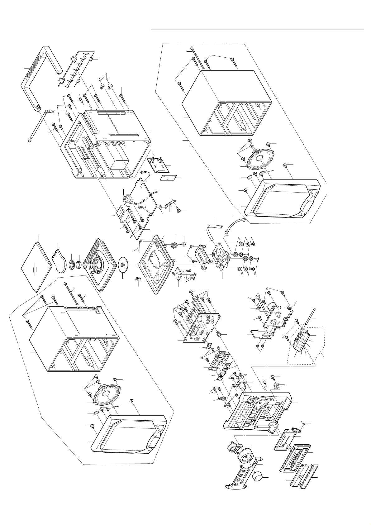
EXPLODED VIEW(CABINET & CHASSIS)
1
3
4
5
10
11
Y01
Y03
Y02
Y02
Y03
Y07
Y08
Y09
Y09
Y11
Y11
Y25
Y25
Y25
Y25
Y25
Y26
Y26
Y26
Y26
Y12
Y12
Y13
Y14
Y15
Y17
Y18
Y19
Y20
Y21
Y22
Y22
Y22
Y22
Y23
Y24
Y10
Y05
Y06
Y06
Y04
12
14
15
17
16
6
7
9
2
13
8
18
19
71
72
73
74
75
20
21
22
23
24
25
26
27
28
29
30
31
32
42
33
34
43
44
45
46
47
49
64
65
64
65
66
66
50
49
51
35
36
37
38
39
40
41
61
62
63
Y27
Y27
Y27
Y27
53
54
52
67
68
55
21A
- 5 -
Page 7

PARTS LIST
PRODUCT SAFETY NOTICE
EACH PRECAUTION IN THIS MANUAL SHOULD BE FOLLOWED DURING SERVICING. COMPONENTS IDENTIFIED WITH
!!
THE IEC SYMBOL
CAN OF SPECIAL SIGNIFICANCE. WHEN REPLACING A COMPONENT IDENTIFIED , USE ONLY THE REPLACEMENT
PARTS DESIGNATED, OR PARTS WITH THE SAME RATINGS OF RESISTANCE, WATTAGE OR VOLTAGE THAT ARE
DESIGNATED IN THE PARTS LIST IN THIS MANUAL. LEAKAGE-CURRENT OR RESISTANCE MEASUREMENTS MUST
BE MADE TO DETERMINE THAT EXPOSED PARTS ARE ACCEPTABLY INSULATED FROM THE SUPPLY CIRCUIT BEFORE
RETURNING THE PRODUCT TO THE CUSTOMER.
CAUTION : Regular type resistors and capacitors are not listed. To know those values, refer to the schematic diagram.
PACKING & ACCESSORIES
REF.NO. PART NO. DESCRIPTION
!!
!
!!
!
CABINET & CHASSIS
REF.NO. PART NO. DESCRIPTION
1 645 060 2917 CASS DOOR COVER
2 645 060 2665 CASS DOOR LENS
3 645 060 2641 LID CASS
4 645 060 2900 CASS DOOR BKT
5 645 049 6240 CASS DOOR SPRING
6 645 060 2726 VOLUME KNOB,ROTARY
7 645 060 2634 FRONT PANEL
8 645 060 2870 VOLUME KNOB RING,
9 645 060 2887 TUNING KNOB RING,
10 645 073 6186 ASSY CABINET FRONT
11 645 026 6454 ASSY,CASS GEAR
12 645 060 2788 TUNING BUTTON,UP/DOWN
13 645 060 2689 REMOTE SENSOR LENS
14 645 060 2757 PRESET BUTTON
15 645 060 2764 BAND BUTTON
16 645 060 2740 STOP/CLEAR BUTTON
17 645 060 2771 PLAY/PAUSE BUTTON
18 645 060 2801 CTL BUTTON SET,
19 645 060 2733 SLIDE KNOB,
20 645 060 2795 BASS BUTTON
21A 645 069 2956 ASSY CASS BUTTON
21 645 060 2818 CASS BUTTON REC
22 645 060 2825 CASS BUTTON PLAY
23 645 060 2832 CASS BUTTON REW
24 645 060 2849 CASS BUTTON FFWD
25 645 060 2856 CASS BUTTON STOP/EJE
26 645 060 2863 CASS BUTTON PAUSE
27 645 049 6257 CASS BUTTON SHAFT
28 645 026 5686 RECORDING BRACKET,
29 645 049 6486 HARD RUBBER,NO:RY-105112 DA11
30 645 049 6479 SOFT RUBBER,NO:RY-105118 DA11
31 645 025 2556 CD BRACKET 9503
32 645 025 1542 ASSY,GEAR CD DOOR
33 645 054 0066 CD BRACKET,
34 645 049 6493 CD DOOR SPRING,S925
35 645 069 3038 SW CD LOCKER
36 645 069 3120 MAGNET CHUCK PLATE
!
IN THE PARTS LIST AND THE SCHEMATIC DIAGRAM DESIGNATE COMPONENTS IN WHICH SAFETY
Regular type resistors are less than 1/4W carbon type and 0 ohm chip resistors.
Regular type capacitors are less than 50V and less than 1000µF of Ceramic type and Electrolytic type.
REF.NO. PART NO. DESCRIPTION
37 645 060 2658 LID CD
645 069 4929 INSTRUCTION MANUAL(XE)
645 069 4912 INSTRUCTION MANUAL(AU)
645 020 3626 POLBAG,FOR AC CORD
645 060 2948 POLYFOAM BOTTOM
645 060 2931 POLYFOAM TOP
645 073 6346 POP CARD
645 047 8703 REMOTE CONTROL,
REMOTE CTL HANDSET
645 073 6261 AC CORD SET,SAA(AU)
645 037 8454 AC LINE CORD,VDE(XE)
645 073 6315 CARTON BOX(AU)
645 073 6322 CARTON BOX(XE)
38 645 025 2549 MAGNET NMB FERRITE CORES
39 645 060 3044 CD MAGNET COVER TOP
40 645 060 2894 CD TUN PLATE,TUN COVER
41 645 060 2672 CD DOOR LENS
42 645 049 6264 BKT PCB MOUNTING,MAIN PCB
43 645 049 6042 BATT COVER PLATE,REAR CAB
44 645 053 9565 ASSY CABINET REAR
45 645 060 2580 BATTERY SPRING ( - ),S925
46 645 053 9862 LID BATTERY
47 645 053 9893 HANDLE
49 645 060 2429 ASSY BOX FRONT
50 645 060 2436 ASSY BOX REAR L
51 645 060 2443 ASSY BOX REAR R
52 645 069 3113 CD MECHANISM DA11V
53 645 060 2467 ASSY SPEAKER BOX L
54 645 060 2474 ASSY SPEAKER BOX R
55 645 069 3045 CASS MECHANISM,
WS-21F DT821 (H) 12V
FIXING PARTS
REF.NO. PART NO. DESCRIPTION
Y01 645 025 2365 SCREW 3X8,CASS EJECT GEAR
Y02 645 016 5078 SCREW,CASS LID
VOLUME KNOB BKT
TUNING KNOB BKT
REPEAT/FM MODE/MEMORY
FUNTION CD/TAPE/RADIO
CASS MECHA
NEVER TOUCH THE LENS
Y03 645 025 2365 SCREW 3X8
Y04 645 025 2365 SCREW 3X8
Y05 645 025 2365 SCREW 3X8
Y06 645 014 1911 SCREW,CD KEY BD TO F PANEL
Y07 645 036 2644 SCR 3X8,CASS KEY SHAFT
Y08 645 026 6164 SCREW 2X4,REC BKT
Y09 645 016 5078 SCREW,CASS MECHA
Y10 645 016 5078 SCREW
Y11 645 036 2606 SCR 2.6X8,CD MECHA
Y12 645 025 2433 FIBER WASHER,FOR CD MECHA
Y13 645 025 2402 SCREW 2X8,CD MECHA BKT
Y14 645 016 5078 SCREW,CD SW BD
Y15 645 049 6288 SCR 3 X 8,EJECT GEAR HOLDER
Y17 645 049 6271 SCR 2.6 X 10
Y18 645 017 1895 FIBRE,WASHER,FOR BKT
Y19 645 049 6271 SCR 2.6 X 10,MAIN PCB
Y20 645 018 3690 SCREW,FOR AC SKT
Y21 645 025 2426 SCREW 3X12,PWR TRANS
Y22 645 049 6295 SCR 3 X 25,F CAB TO R CAB
Y23 645 018 3690 SCREW,CD HEAD REAR CAB
Y24 645 036 2644 SCR 3X8,FM ANT
Y25 645 018 0521 SCREW,SPK NET
Y26 645 025 2372 SCREW 3X8,SPK BOX
Y27 645 026 6218 SCREW 3X20,SPK BOX
- 6 -
Page 8

PARTS LIST
ELECTRICAL-PARTS
REF.NO. PART NO. DESCRIPTION
61 645 027 0000 6P J.WIRE AWG28UL,
CN603 TO CD MECHA
62 645 060 2566 16P FILM CABLE,
CN602 TO CD MECHA
63 645 049 5847 ROD ANTENNA
64 645 049 5786 BUZZER
65 645 049 5779 5" SPK,W/BLACK CAP
66 645 049 5694 2P J WIRE AWG22UL,SPK TO MAIN
67 645 038 2321 PWR TRANS
or 645 073 6254 POWER TRANSFORMER
68 645 022 1590 AC SOCKET
645 016 1919 2P J.WIRE AWG26UL,
CTL CNP701 TO SW CN701
645 060 2528 2P J WIRE AWG26UL,
MAIN CN302 TO BATT CNP30
645 060 2535 2P S SHIELD WIRE AWG,
CTL CNP801 TO MAIN CN801
645 026 9332 4P J.WIRE AWG26UL,
MAIN CN301 TO TAPE MOTOR
645 041 6453 4P 3 CORE SHIELD W,
TAPE HEAD TO CN1
645 069 2994 8P F WIRE UL,CNP601 TO CN601
645 049 5724 8P F WIRE UL,CNP102 TO CN102
645 049 5731 15P F WIRE UL,CNP303 TO CN303
645 049 5755 10P TML, 9 JIS D SH,
CNP802 TO CN802
DISPLAY P.W.BOARD ASSY
REF.NO. PART NO. DESCRIPTION
71 614 332 6137 ASSY,PWB,DISPLAY,CTL KEY
(Only initial)
C0101 403 060 6904 POLYESTER 3300P M 50V
C0201 403 060 6904 POLYESTER 3300P M 50V
C0714 403 135 4507 ELECT 1000U M 10V
CN701 645 014 1218 2P WAFFR H-TYPE
D0702 645 060 2511 DIODE 1SS133
D0703 645 060 2511 DIODE 1SS133
D0704 645 060 2511 DIODE 1SS133
D0705 645 016 8956 SW DIODE 1N4148
D0706 645 016 8956 SW DIODE 1N4148
D0707 645 016 8956 SW DIODE 1N4148
D0708 645 016 8956 SW DIODE 1N4148
D0709 645 016 8956 SW DIODE 1N4148
D0710 645 016 8956 SW DIODE 1N4148
D0711 645 016 8956 SW DIODE 1N4148
D0712 645 016 8956 SW DIODE 1N4148
D0713 645 016 9250 RECTIFIER
D0714 645 016 8956 SW DIODE 1N4148
D0715 645 016 8956 SW DIODE 1N4148
D0716 645 016 8956 SW DIODE 1N4148
D0717 645 016 8956 SW DIODE 1N4148
D0721 645 016 8956 SW DIODE 1N4148
IC702 645 060 2504 IC LC72336 9B62
L0701 645 021 5438 AXIAL INDUCTOR 10UH
LD701 645 049 5854 LCD DISPLAY
Q0701 645 016 9205 TRANSISTOR
Q0702 645 016 9205 TRANSISTOR
Q0703 645 016 9205 TRANSISTOR
Q0704 645 016 9205 TRANSISTOR
Q0705 645 041 4459 TR 2SA1522
Q0706 645 026 8540 TRANSISTOR,2SC3916
Q0707 645 026 8540 TRANSISTOR,2SC3916
Q0708 645 026 8540 TRANSISTOR,2SC3916
Q0709 645 026 8540 TRANSISTOR,2SC3916
Q0710 645 016 9205 TRANSISTOR
RX701 645 060 2597 REMOTE RECEIVER,
INFRARED DETECTOR
S0701 645 041 4596 TACT SW KTL-TC-0103,PRESET
or 645 069 2970 SWITCH TACT,PRESET
S0702 645 041 4596 TACT SW KTL-TC-0103,BAND
or 645 069 2970 SWITCH TACT,BAND
S0703 645 041 4596 TACT SW KTL-TC-0103,REW
or 645 069 2970 SWITCH TACT,REW
REF.NO. PART NO. DESCRIPTION
S0704 645 041 4596 TACT SW KTL-TC-0103,STOP
or 645 069 2970 SWITCH TACT,STOP
S0705 645 041 4596 TACT SW KTL-TC-0103,PLAY
or 645 069 2970 SWITCH TACT,PLAY
S0706 645 041 4596 TACT SW KTL-TC-0103,FWD
or 645 069 2970 SWITCH TACT,FWD
S0707 645 041 4596 TACT SW KTL-TC-0103,MEMORY
or 645 069 2970 SWITCH TACT,MEMORY
S0708 645 041 4596 TACT SW KTL-TC-0103,REPEAT
or 645 069 2970 SWITCH TACT,REPEAT
SW101 645 049 5670 SW SLIDE,SS43D01M10
SW102 645 036 2002 SWITCH PUSH,PS-22E08L-0
VR101 645 036 3122 ROTARY VR
XT701 645 049 5861 CRYSTAL 4.5MHZ
CASS P.W.BOARD ASSY
REF.NO. PART NO. DESCRIPTION
72 614 332 6144 ASSY,PWB,CASS(Only initial)
C0001 403 061 9003 POLYESTER 4700P M 50V
C0002 403 059 4409 POLYESTER 2200P M 50V
C0003 403 059 4409 POLYESTER 2200P M 50V
C0004 403 061 9003 POLYESTER 4700P M 50V
C0005 403 063 0800 POLYESTER 6800P M 50V
C0006 403 063 0800 POLYESTER 6800P M 50V
C0007 403 061 9003 POLYESTER 4700P M 50V
C0008 403 061 9003 POLYESTER 4700P M 50V
C0014 403 058 1904 POLYESTER 1500P M 50V
C0016 403 058 1904 POLYESTER 1500P M 50V
C0018 403 060 1305 POLYESTER 2700P M 50V
C0020 403 061 9003 POLYESTER 4700P M 50V
C0026 403 057 1202 POLYESTER 0.01U M 50V
CN001 645 017 2045 4P WAFER
CN102 645 026 8823 8P WAFTR
IC001 645 041 6408 IC TA7668BP
Q0002 645 025 1665 TR 2SC3330U
Q0003 645 025 1641 TR 2SA1346-AC
Q0004 645 016 9205 TRANSISTOR
SW001 645 049 5687 SW PUSH,0820250/PS 825
T0001 645 014 1058 BIAS/OSC,AHK809461
CD SW P.W.BOARD ASSY
REF.NO. PART NO. DESCRIPTION
73 614 332 6113 ASSY,PWB,CD SW,CD DOOR SW
(Only initial)
SW701 645 025 1818 MICRO SW LF-101-0,LF-101-0
CD MAIN P.W.BOARD ASSY
REF.NO. PART NO. DESCRIPTION
74 614 332 6120 ASSY,PWB,CD MAIN(Only initial)
C0110 403 057 3800 POLYESTER 0.1U M 50V
C0111 403 125 5507 ELECT 1000U M 16V
C0210 403 057 3800 POLYESTER 0.1U M 50V
C0211 403 125 5507 ELECT 1000U M 16V
C0312 403 135 5702 ELECT 4700U M 25V
C0602 403 059 8902 POLYESTER 0.22U M 50V
C0603 403 060 8908 POLYESTER 0.033U M 50V
C0606 403 060 6904 POLYESTER 3300P M 50V
C0607 403 062 1105 POLYESTER 0.047U M 50V
C0608 403 058 6008 POLYESTER 0.15U M 50V
C0613 403 056 8905 POLYESTER 1000P M 50V
C0614 403 057 3800 POLYESTER 0.1U M 50V
C0615 403 058 4004 POLYESTER 0.015U M 50V
C0616 403 059 0708 POLYESTER 0.018U M 50V
C0617 403 060 6904 POLYESTER 3300P M 50V
C0622 403 060 6904 POLYESTER 3300P M 50V
C0633 403 057 1202 POLYESTER 0.01U M 50V
C0638 403 060 8908 POLYESTER 0.033U M 50V
C0640 403 059 4409 POLYESTER 2200P M 50V
C0645 403 057 3800 POLYESTER 0.1U M 50V
C0646 403 057 3800 POLYESTER 0.1U M 50V
C0651 403 135 4507 ELECT 1000U M 10V
C0811 403 058 1904 POLYESTER 1500P M 50V
C0813 403 057 1202 POLYESTER 0.01U M 50V
C0815 403 057 1202 POLYESTER 0.01U M 50V
C0842 403 060 8908 POLYESTER 0.033U M 50V
- 7 -
Page 9

PARTS LIST
REF.NO. PART NO. DESCRIPTION
C0844 403 060 8908 POLYESTER 0.033U M 50V
CF801 645 020 2988 CERAMIC DISCRIMINATOR
CF802 645 049 5762 CERAMIC FILTER
CF803 645 049 5762 CERAMIC FILTER
CF804 645 027 7672 CERAMIC FILTER
CN101 645 026 8816 2P WAFFR
CN201 645 026 8816 2P WAFFR
CN301 645 025 1917 4P WAFER
CN303 645 049 5748 15P WAFER
CN601 645 026 8823 8P WAFTR
CN602 645 060 2542 16P STRAIGHT CONNECT,FFC
CN603 645 017 2052 6P WAFER
CN801 645 016 9342 2P WAFER
CN802 645 014 1232 9P WAFTR V-TYPE
D0301 645 016 9250 RECTIFIER
D0306 645 016 9250 RECTIFIER
D0307 645 016 9250 RECTIFIER
D0308 645 016 9250 RECTIFIER
D0309 645 016 9250 RECTIFIER
D0313 645 016 8956 SW DIODE 1N4148
D0601 645 060 2511 DIODE 1SS133
D0801 645 016 8956 SW DIODE 1N4148
D0802 645 016 8956 SW DIODE 1N4148
FU001 645 014 1447 1.6A APP FUSEDIA5X20 250V,FU1
FU002 645 026 7925 PROTECTOR,LITTEL FUSE
IC101 645 060 2481 IC UTC TA8227P
IC601 645 060 2498 IC LA9242M
IC602 645 025 1610 IC LC78622E
IC603 645 025 1580 IC LA6541D
IC801 645 049 5649 IC LA1823
JACK1 645 036 4372 ST.PHONE JACK,EJS-7-1535B
L0601 645 026 7857 AXIAL INDUCTOR
L0602 645 026 7857 AXIAL INDUCTOR
L0604 645 026 7857 AXIAL INDUCTOR
L0801 645 020 9338 FM COIL
L0802 645 041 4589 FM COILS
L0803 645 014 1072 FM COIL
L0804 645 020 9338 FM COIL
Q0101 645 025 1658 TR 2SD1936-U-AC
Q0201 645 025 1658 TR 2SD1936-U-AC
Q0301 645 036 1937 TR 2SD882
REF.NO. PART NO. DESCRIPTION
Q0302 645 027 3162 TR 2SD400-F-MPC
Q0600 645 069 2963 TR 2SA608NF NPA WA
Q0601 645 025 1627 TR 2SB764E
Q0801 645 041 4473 TR 2SC2999D
Q0802 645 016 9205 TRANSISTOR
R0304 401 006 9903 CARBON 100 JA 1/2W
SC01 645 025 2396 SCREW 3X8,FOR Q301
SW301 645 027 7634 SWITCH,TACT,IH-1236A
SW901 645 016 1896 SWITCH,SK23D04 G9
T0801 645 027 7603 OSC COIL,AM OSC
T0802 645 049 5663 AM IFT,OH-827538-00
TC801 645 032 4451 TRIMMER 20PF,PHILIPS
TC802 645 016 6495 TRIMMER,PHILIPS
TD801 645 043 7564 TUNING DIODE SVC348
TD802 645 027 7573 TUNING DIODE SVC 201SPA
TD803 645 027 7573 TUNING DIODE SVC 201SPA
XT601 645 036 3573 CERAMIC RESONATOR
ZD301 645 025 1696 ZENER
ZD302 645 027 7566 ZENER DIODE 5.6V
ZD801 645 036 2804 ZENER 4.7V
645 041 6422 BEAD COIL 25UH,FM ANT
645 014 2246 FUSE HOLDER,FOR FU1
645 020 3503 TEST PINS,ANT
645 026 5716 NUT M3,FOR Q301
645 036 2668 HEAT SINK,FOR IC101
645 036 2675 HEAT SINK B,FOR Q301
645 060 2573 SOLID WIRE
645 060 2559 FERRITE CORE,CN801 WIRE
645 069 2949 ASSY BAR ANT
BATTERY P.W.BOARD ASSY
REF.NO. PART NO. DESCRIPTION
75 614 331 2451 ASSY,PWB,BATTERY(Only initial)
CNP302 645 026 8816 2P WAFFR
J099A 645 060 2573 SOLID WIRE
J099B 645 060 2573 SOLID WIRE
J099C 645 060 2573 SOLID WIRE
J099D 645 060 2573 SOLID WIRE
645 060 2580 BATTERY SPRING ( - ),S925
IC BLOCK DIAGRAM & DESCRIPTION
IC001 TA7668BP (PRE AMP W/2ch ALC)
Rec.
OUT
Mute
Mute
1
OUT
IN
15345
Mute
OUT
DND
Rre.IN
NF.
Pre.IN
ALC
Pre.IN
Pre.IN
NF.
6
7
8
10
11
Pre.OUT
& Rec.IN
Pre
ALC DET
Pre
Rec.
& Rec.IN
DND
Pre OUT
Rec
Rec
ch
Rec.
OUT
11413129
Rec.
IC603 LA6541 (CD Driver)
Vcc Vref VIN4 VG4 Vo8 Vo7 GND Vo6 Vo5 VG3 VIN3 CD RES
11k Ω 11k Ω
Vcc
16
2
Vs.
Vcc Mute VIN1 VG1 Vo1 Vo2 GND Vo3 Vo4 VG2 VIN2 Reg OUT Reg IN
Level
Sift
Level
Sift
123 456 789
BTL
Driver
BTL
Driver
Vcc
BTL
Driver
BTL
Driver
Level
Sift
Level
Sift
11k Ω11k Ω
10 11 12
131415161718192021222324
RESET
Regulator
- 8 -
Page 10

IC BLOCK DIAGRAM & DESCRIPTION
68
66
67
65
19
20
21
22
64
63
62
61
23
24
25
26
27
29
30
28
32
33
34
35
36
37
38
39
40
41
42
43
44
45
46
47
48
49
50
51
52
53
54
55
59
60
56
57
58
78
77 E01
E02
COM1
COM2
COM3
Vdd2
Vdd1
S1
S2
S3
S4
S5
S6
S7
S8
S9
S10
S11
S15
S12
S13
S14
S16
S17/PE0
S18/PE1/SCK2
S19/PE2/SO2
S20/PE3/SI2
S21/PF0
S22/PF1/SCK1
S23/PF2/SO1
S24/PF3/SI1
S28/PM3
S25/PM0
S26/PM1
S27/PM2
S29/PN0/BEEP
S31/PN2
S30/PN1
S32/PN3
PJ3/DAC3
PJ2/DAC2
PJ1/DAC1
PJ0/DAC0
PK3
PK2
PK1/INT1
PK0/INT0
PH3/ADI3
PH2/ADI2
PH1/ADI1
PH0/ADI0
1
80
74
XIN
XOUT
FMIN
75
72
73
76
70
71
AMIN
SNS
HOLD
VDD
VSS
HCTR
LCTR
69
79
2
18
17
16
15
14
13
12
11
10
9
8
7
TEST1
TEST2
PA0
PA1
PA2
PA3
PB0
PB1
PB2
PB3
PC0
PC1
PC2
PC3
6
5
4
3
PG0
SCK0/PG1
SO0/PG2
SI0/PG3
LATCH
BUS
DRIV.
LATCH
BUS
DRIV.
LATCH
BUS
DRIV.
SIO
BUS
DRIV.
1 / 2
V-DET
SNSFF
1 / 16,1 / 17
PROGRAMMABLE DIVIDER
LATCH
UNIVERSAL
COUNTER
(20bits)
RAN
512 x 4bits
RAN
6K x 16bits
ADDRESS
DECODER
BUS
DRIVER
INSTRUC-
TION
DECODER
ADDRESS DECODER
PROGRAM COUNTER
STACK
JUDGE
ALU
DAC
ADC
LATCH
BUS
DRIV.
LATCH
BUS
DRIV.
LATCH
BUS
DRIV.
LATCH
BUS
DRIV.
LATCH
BUS
DRIV.
LATCH
BUS
DRIV.
LATCH
BUS
DRIV.
MPX
INTERRUPT
MPX
MPX
MPX
MPX
MPX
BEEP
LCPA/B
LCDA/B
SEG
PLA
LATCH
LCD
PORT
DRIVER
96
4
4
7
SELECTER
PHASE
DETECTOR
UNLOCK
F/F
COMMON
DRIVER
REFERENCE DIVIDERDIVIDER
IC602 LC78622 (Digital Signal Processor)
DEFI
EFMIN
FSEQ
CLV+
CLV-
V/P
PW
SBCK
SBSY
SFSY
CS
WRQ
SQOUT
CQCK
COIN
RWC
1
10
Syncrnous Detect
22
EFM Demodulation
12
13
14
49
51
Subcode Dxract
47
50
63
53
55
57
56
54
EFMO VVDDVVSSPDO ISET FR PCK TAI
9
Slice level
Control
CLV
Digital Servo
QCRC
µCOM
Inter Fase
Servo Commander
4
6
VCO Clock Oscillator
& Clock Control
General Ports
357 2
TEST2 TEST4
TEST11
TEST1 TEST3 TEST5
21
59 64 11 32 33 62
2K
RAM
C1 C2 Error Detect &
Correct Control Flag
X'tal Root
Timing Generator
VDDV
SS
23
8
X
8bit
RAM Address
Generatorl
Interpolalation Mute
C2F
30
Billingual
Digital Out
31
DOUT
Digital Attenuator
Quadruple Over Sampling
Digital Filter
(NC)
1bit DAC
34
L.P.F
15 16 17 20 19 58 18 24 25 26 27 28 29 48 60 61 46 52 45 44 43 39 41 42 40 37 35 38 36
TGL
RESJP+JP-TOFFTESHFL
IC070 LC723369557 (LCD Driver)
CONT1
CONT2
CONT3
CONT4
4.2M16MEFLGEMPHCONT5
XV
SS
XINFSX
XOUT
XV
DD
RV
RV
DD
RCHO
SS
MUTER
MUTELLCHO
DD
LV
LV
SS
- 9 -
Page 11

IC BLOCK DIAGRAM & DESCRIPTION
IC070 LC723369557 (LCD Driver)
XIN
XOUT
FMIN
AMIN
SNS
VDD
VSS
HCTR
LCTR
HOLD
TEST1
TEST2
PA0
PA1
PA2
PA3
PB0
PB1
PB2
PB3
PC0
PC1
PC2
PC3
PG0
SCK0/PG1
SO0/PG2
SI0/PG3
80
74
75
72
73
76
70
71
69
79
18
17
16
15
14
13
12
11
10
1
1 / 16,1 / 17
SNSFF
V-DET
1 / 2
2
BUS
DRIV.
LATCH
BUS
DRIV.
9
8
7
6
5
4
3
LATCH
BUS
DRIV.
SIO
LATCH
BUS
DRIV.
REFERENCE DIVIDERDIVIDER
PROGRAMMABLE DIVIDER
LATCH
UNIVERSAL
COUNTER
(20bits)
RAN
512 x 4bits
RAN
6K x 16bits
ADDRESS DECODER
PROGRAM COUNTER
STACK
ALU
SELECTER
ADDRESS
DECODER
BUS
DRIVER
INSTRUCTION
DECODER
JUDGE
DAC
PHASE
DETECTOR
UNLOCK
F/F
LCDA/B
4
SEG
4
PLA
LCPA/B
BEEP
7
LATCH
BUS
DRIV.
LATCH
BUS
DRIV.
LATCH
BUS
DRIV.
LATCH
BUS
DRIV.
LATCH
BUS
DRIV.
COMMON
DRIVER
LATCH
MPX
96
MPX
MPX
MPX
MPX
LCD
PORT
DRIVER
77 E01
78
E02
58
COM1
57
COM2
56
COM3
Vdd1
60
59
Vdd2
S1
55
54
S2
53
S3
52
S4
51
S5
50
S6
49
S7
S8
48
S9
47
46
S10
S11
45
44
S12
43
S13
S14
42
41
S15
40
S16
39
S17/PE0
38
S18/PE1/SCK2
S19/PE2/SO2
37
36
S20/PE3/SI2
S21/PF0
35
34
S22/PF1/SCK1
33
S23/PF2/SO1
S24/PF3/SI1
32
30
S25/PM0
29
S26/PM1
28
S27/PM2
27
S28/PM3
26
S29/PN0/BEEP
25
S30/PN1
24
S31/PN2
23
S32/PN3
61
PJ3/DAC3
62
PJ2/DAC2
63
PJ1/DAC1
64
PJ0/DAC0
ADC
- 10 -
LATCH
BUS
DRIV.
MPX
LATCH
BUS
DRIV.
INTERRUPT
19
PK3
20
PK2
21
PK1/INT1
22
PK0/INT0
65
PH3/ADI3
66
PH2/ADI2
67
PH1/ADI1
68
PH0/ADI0
Page 12

IC BLOCK DIAGRAM & DESCRIPTION
IC602 LC78622 (Digital Signal Processor)
Terminal
No.
Terminal
symbols
1 DEFI I
2 TAI I Input terminal for test. Pull-down resistor incorporated. Make sure to ground.
3 PDO O Output terminal for phase-comparator for external VCO control.
4 VVSS - For PLL Ground terminal for internal VCO. Make sure to ground.
5 ISET AI Resistive connection terminal for current regulation of PDO output.
6 VVDD - Power terminal for internal VCO.
7FRAI For VCO frequency range control.
8 VSS 9 EFMO O Output terminal for EFM signals.
10 EFMIN I Input terminal for EFM signals.
11 TEST2 I
12 CLV+ O
13 CLV- O
14 V/*P O
15 HFL I
16 TEST2 I
17 TOFF O
18 TGL O
19 JP+ O
20 JP- O
21 PCK O
22 FSEQ O
23 VDD -
24 CONT1 I/O
25 CONT2 I/O
26 CONT3 I/O
27 CONT4 I/O
28 CONT5 I/O
29
30 C2F O
31 DOUT O
32 TEST3 I
33 TEST4 I
34 PCCL I
35
36 LVDD -
37 LCHO O
38 LVSS 39 RVSS 40 RCHO O
41 RVDD -
42
EMPH/
CONT6
MUTEL/C
ONT7
MUTER/C
ONT8
I/O
Input terminal for defect detection signals (DEF). (Ground when not used.)
Ground terminal for digital signals. Make sure to ground.
For slice level
control
Input terminal for test. Pull-down resistor incorporated. Make sure to ground.
Output for disk motor control. 3 values can be output by a command.
Output terminal for automatic switching monitor between rough servo and phase control. (Rough servo on "H"position,
phase servo on "L".
Input terminal for track detection signals. Schmitt input.
Input terminal for tracking error signals. Schmitt input.
Output terminal for tracking-off.
Output terminal for tracking gain switching. "L" position increases gain.
Output for track jump control. 3 values can be output by a command.
Terminal for clock monitor for EFM data reproduction. 4.3218 MHz when phase locked.
Output terminal for synchronizing signal detection. "H" position when the synchronizing signals detected in EFM signals
match with the synchronizing signals generated internally.
Power terminal for digital signals.
Generalized I/O terminal 1
Generalized I/O terminal 2
Generalized I/O terminal 3
Generalized I/O terminal 4
Generalized I/O terminal 5
Terminal for de-emphasis monitor. De-emphais disk is being reproduced while in the "H" position. Or generalized Output
O
terminal 6.
Output terminal for C2 flag.
Output terminal for digital OUT. (EIAJ format)
Input terminal for test. Pull-down resistor incorporated. Make sure to ground.
Input terminal for test. Pull-down resistor incorporated. Make sure to ground.
Generalized I/O terminal for command identification. Pull-down resistor incorporated. When used as the same function
as LC78622E, open circuit or ground. ("H" position: enables only generalized I/O command to be controlled. "L" position:
enables all the c
O
L channel 1bit DAC
R channel 1bit DAC
O
Mute output terminal for L channel. Or generalized output terminal 7.
Power terminal for L channel.
Output terminal for L channel.
Ground terminal for L channel. Make sure to ground.
Ground terminal for R channel. Make sure to ground.
Output terminal for R channel.
Power terminal for R channel.
Mute output terminal for R channel. Or generalized output terminal 8.
Controlled by a serial data command from micro-computer. When not used, either use
as input terminal and then ground or use as output terminal and then open circuit.
DESCRIPTION
- 11 -
Page 13

IC BLOCK DIAGRAM & DESCRIPTION
IC602 LC78622 (Digital Signal Processor)
Terminal
No.
Note: Each power terminal (VDD, VVDD, LVDD, RVDD and XVDD) must be supplyed with the same voltage.
Terminal
symbols
43 XVDD 44 XOUT O
45 XIN I
46 XVSS 47 SBSY O
48 EFLG O
49 PW O
50 SFSY O
51 SBCK I
52 FSX O
53 WRQ O
54 RWC I
55 SQOUT O
56 COIN I
57 *CQCK I
58 *RES I
59 TST11 O
60 16M O
61 4.2M O
62 TEST5 I
63 *CS I
64 TEST1 I
I/O
DESCRIPTION
Power terminal for crystal oscillator
Joining terminal for crystal resonator (16.9344 MHz)
Ground terminal for crystal oscillator. Make sure to ground.
Output terminal for synchronizing signals of sub-code clock.
Monitor terminal for 1 bit or 2 bit error correction
Output terminal for sub-code P, Q, R, S, T, U or W.
Output terminal for synchronizing signals of sub-code frame. When sub-code is stood by, falls.
Input terminal for clock to read out sub-code. Schmitt input (when not used, make sure to ground.)
Output terminal for synchronizing signal (7.35 kHz) which is divided from crystal oscillator.
Output terminal for Q output standby of sub-code.
Input terminal for read/write control. Schmitt input.
Output terminal for Q output of sub-code.
Input terminal for command from micro-computer.
Input terminal either for clock to take in command input or for clock to take out sub-code from SQOUT. Schmitt input.
Input terminal for reseting this LSI. Switches to "L" position for a moment at power-on.
Output terminal for test. Make sure to open circuit. (Normally "L" output)
Output terminal of 16.9344 MHz
Output terminal of 4.2336 MHz
Input terminal for test. Pull-down resistor incorporated. Make sure to ground.
Input terminal for chip selecting. Pull-down resistor incorporated. Make sure to ground when not controlled.
Input terminal for test. No pull-down resistor. Make sure to ground.
IC801 LA1823 (Tuner)
- 12 -
Page 14

WIRING DIAGRAM (BATTERY,CD SW,CASS)
BATTERY
A SIDE
B SIDE
CD SW
A SIDE B SIDE
CASS
- 13 -
Page 15

SCHEMATIC DIAGRAM (MAIN)
This is a basic schematic diagram.
- 15 -- 14 -
Page 16

SCHEMATIC DIAGRAM (CD MAIN)
This is a basic schematic diagram.
- 17 -- 16 -
Page 17

WIRING DIAGRAM (CD MAIN)
A SIDE
- 18 -
B SIDE
Page 18

WIRING DIAGRAM (DISPLAY )
A SIDE
Aug./ '04 BB Printed in Japan
B SIDE
SANYO Electric Co., Ltd.
Osaka, Japan
- 19 -
 Loading...