

Sanyo LNS-T03 User Manual
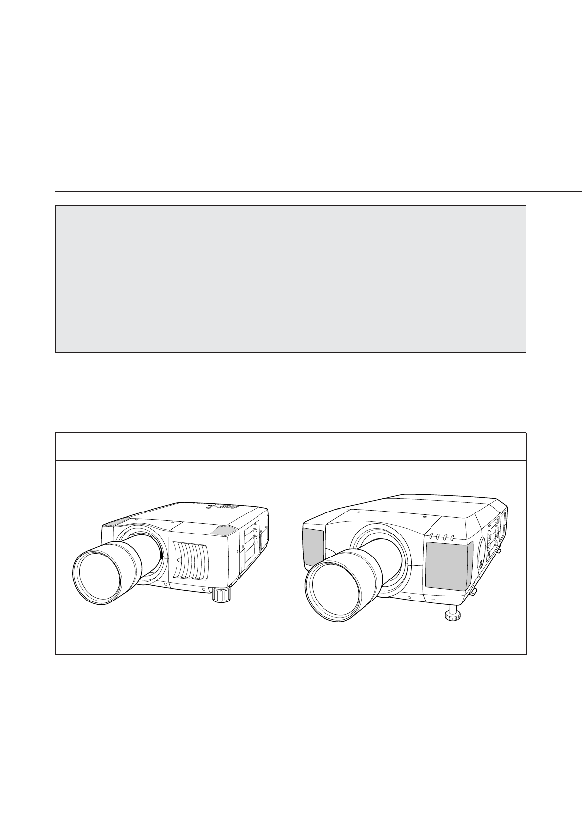
Type of the Cabinet (1) (See Page 2)
LCD PROJECTOR LENS
MODEL NO. LNS-T03
LENS REPLACEMENT
AND INSTALLATION PROCEDURES
NOTES ON REPLACEMENT AND INSTALLATION
The procedures and the needed pars for lens installation depend on the type of
cabinet. Before installing or replacing the lens, make sure the type of cabinet of your
projector.
When installing or replacing the lens, make sure the Lens Model No. matches with to
your projector. Refer to the catalog, or contact your sales dealer for the proper Lens
Model No.
TYPE OF THE CABINET AND INSTALLATION PROCEDURES
Check the type of cabinet of your projector and follow the respective installation procedure
to install the lens correctly.
Type of the Cabinet (2) (See Page 5)
1AA6P1P4097-- (IDLS)
For lens installation to the other models than above, contact your sales dealer.
Not all the parts included may be used for lens installation or replacement. Keep these
parts for later use.
Note : Illustrations in this manual may differ from the actual product.
NOTES ON LENS INSTALLATION
• Lens installation and replacement should be made by the qualified service personnel.
• Be sure to install the lens following this procedure precisely.
• The lens cover is attached to the lens for protection. Be sure to remove the lens
cover from the lens before installation.
• When installing or replacing the lens, be careful not to stain, scratch or damage
its surface.
After installing or replacing the lens, be sure to confirm the followings for safety.
1. Make sure the lens is fixed on the projector.
2. Make sure no part is missing, or loose.
BE SURE TO CHECK THE FOLLOWING MATTERS FOR SAFETY
LIST OF CONTENTS
Following parts are included in the package.
• LENS 1 pc
• DRIVER 1 pc
-1-
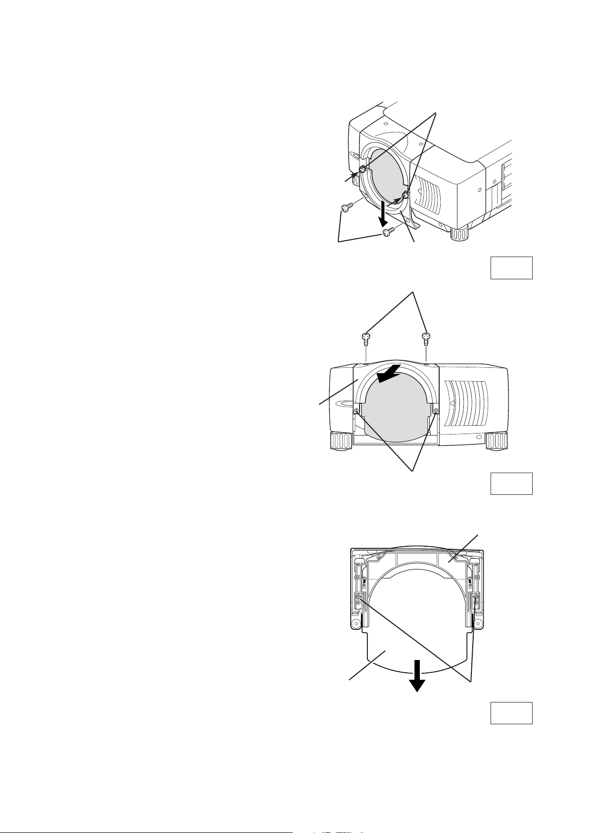
LENS REPLACEMENT AND INSTALLATION PROCEDURE
{Type (1) Cabinet}
-2-
1
Remove 2 Screws A and Remove Lower Lens
Cover. Push part B and pull the Lower Lens
Cover down and remove it. (See Fig. 1.)
2
Remove 4 Screws C. Pull the Upper Lens Cover
toward front and remove it. (See Fig. 2.)
3
Remove 2 Screws D and Cover Plate from the
back of the Upper Lens Cover. (See Fig. 3.)
A
C
C
B
Fig-3
Fig-1
Fig-2
UPPER LENS
COVER
COVER PLATE
UPPER LENS
COVER
LOWER LENS
COVER
D
 Loading...