

SANYO LNSS30 User Manual

Following checks and confirmations should be taken for safety.
Check the following things by the time of the cabinet assembly after the lens
replacement.
1. Check the lens is securely fixed.
2. Check the proper wiring and the wires are fixed properly.
3. Check each connector is connected properly.
4. Check no wiring is tangled on the gear of lens motor or the other mechanical parts.
5. Check no parts is missing, or no mounting part is loose.
LCD PROJECTOR LENS
MODEL LNS-S30/S31
LENS REPLACEMENT PROCEDURE
NOTES ON LENS REPLACEMENT
Lens replacement should be performed by the qualified service personnel.
It should be followed by this procedure precisely.
Before attempt to replace the lens, confirm the model number (both the LCD
projector and the lens) and use the proper lens.
The lens cover is on the lens for protection. Be sure to remove the lens cover
before installation.
When installing or removing the lens, be careful not to stain, scratch or
damage the lens.
If you have any questions, contact the dealers.
Following parts are contained in the packing.
1AA6P1P3245-- (IDEJ)
PARTS LIST
● LENS
● DRIVER (3 mm, Green)
● DRIVER (4 mm, Yellow)
● LIGHT-BLOCK SHEET For LNS-S30
For LNS-S31
1 piece
1 piece (Part No. 610 287 7328)
1 piece (Part No. 610 275 6029)
1 piece Type PA1 (Part No. 610 285 3735)
1 piece Type PE1 (Part No. 610 293 9804)
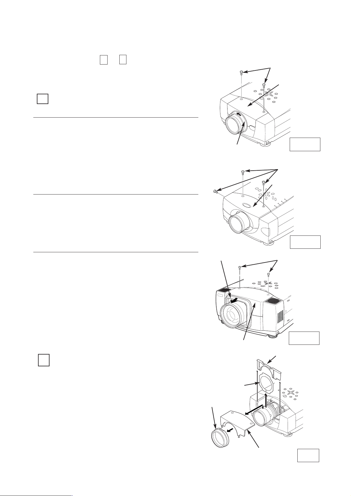
Turn the lens cover to counter-clockwise and
pull it toward front and remove the Lens
Cover.
Remove 2 Screws-A.
Remove the front cabinet
REMOVE THE LENS COVER AND
FRONT CABINET
1
1.
2.
2
REMOVE THE LIGHT-BLOCK SHEET BASE
AND LIGHT-BLOCK SHEET (See Figure-2)
Perform the steps
to
for lens replacement.
1
6
First set the lens at the fully lower position with
lens shift adjustment.
3.
Slide the light-block sheet base upward
and remove it.
Remove the light-block sheet from lens.
1.
2.
Fig-2
LIGHT-BLOCK
SHEET BASE
FRONT
CABINET
LENS COVER
LIGHT-BLOCK
SHEET
LENS REPLACEMENT PROCEDURE
SCREW "A"
SCREW "A"
SCREW "A"
Fig-1-1
Fig-1-2
Fig-1-3
Remove 2 Screws-A.
Remove the front cabinet
See Figure-1-2 and 2.
1.
2.
Pull Lens Cover toward front and remove it.
Remove 2 Screws-A.
Remove the front cabinet
See Figure-1-3 and 2.
1.
2.
3.
LENS COVER
FRONT CABINET
LENS COVER
FRONT CABINET
FRONT CABINET
-2-
See Figure-1-1 and 2.
4
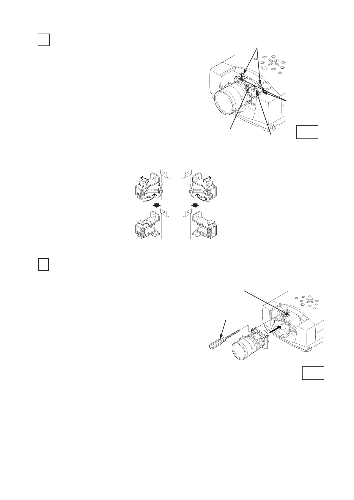
MOUNT THE LENS (See Figure-5)
Remove protective caps (front and back) on the
lens.
Mount the lens on lens mounting bracket with
Upper 2 screws. (locate motor on left side).
Use the driver included with the lens to fasten the
screws.
Slide the lens lock latches to "LOCK" position and
lock the lens. (See Figure-4)
Connect the lens motor connector to terminal.
(See Figure-3)
1.
2.
3.
4.
DRIVER
IN THE LENS
LENS MOUNTING
BRACKET
Fig-5
Fig-3
SCREW "B"
LENS LOCK
LATCHES
CONNECTOR
3
REMOVE THE LENS (See Figure-3 and 4)
Remove the lens motor connector from terminal.
Loosen the screws-B (2 screws) which fastens
the lens. (Use the driver included with the lens to
loosen the screws.)
Slide the lens lock latches to "UNLOCK" position
and remove the lens.
1.
2.
Be careful not to drop the lens when removing the
screws. After using, save the driver for latter use.
3.
TERMINAL
LENS LOCK LATCHES
LOCK
POSITION
UNLOCK
POSITION
Fig-4
-3-
 Loading...