

Page 1
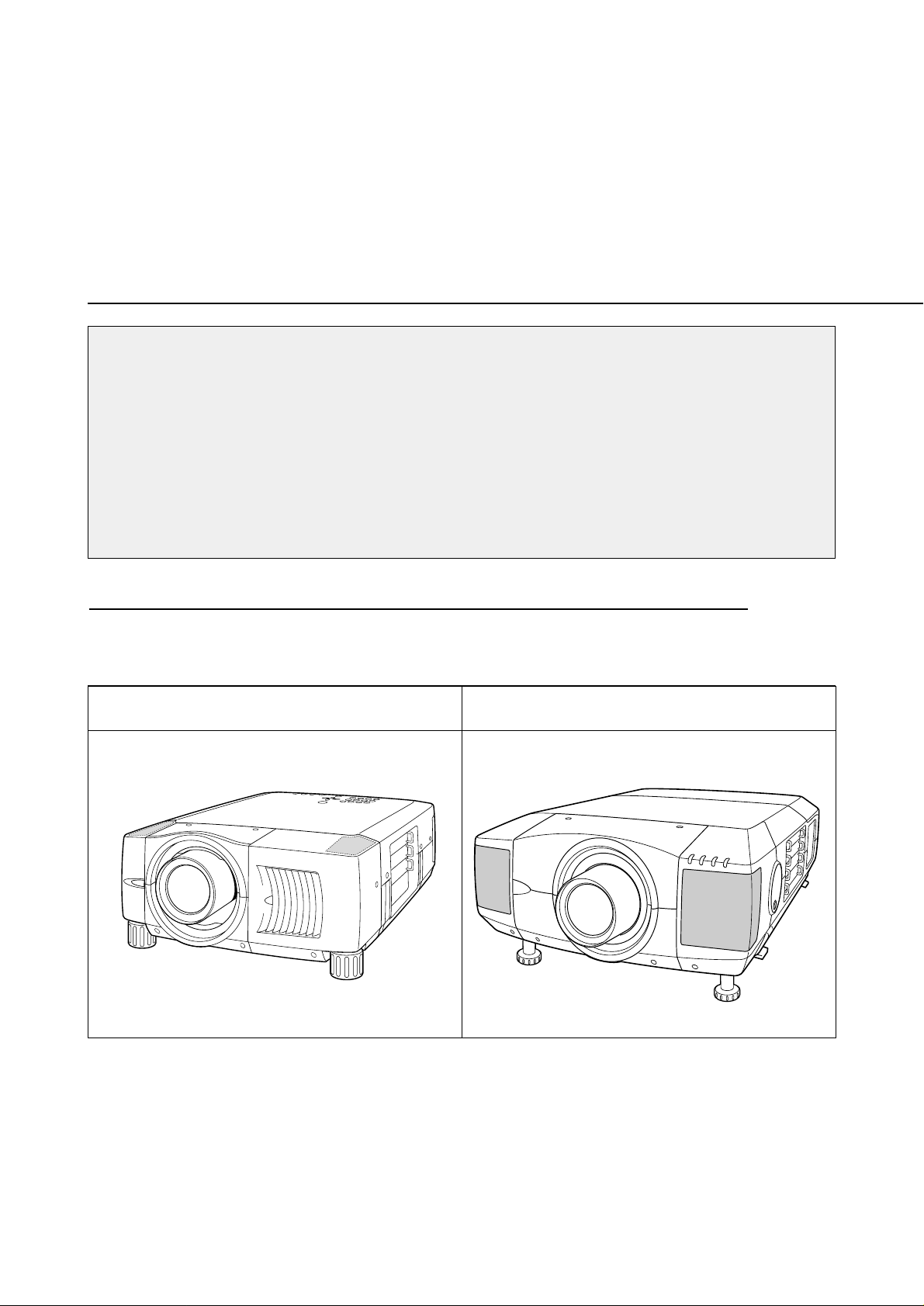
Type of the Cabinet (1) See Page 2
LCD PROJECTOR LENS
MODEL NO. LNS-S03
LENS REPLACEMENT
AND INSTALLATION PROCEDURES
NOTES ON REPLACEMENT AND INSTALLATION
The procedures and the needed pars for lens installation depend on the type of
cabinet. Before installing or replacing the lens, make sure the type of cabinet and be
sure to refer to the Installations corresponding with your projector.
When installing or replacing the lens, make sure the Lens Model No. matches with
your projector. Refer to the catalog, or contact your sales dealer for the proper Lens
Model No.
TYPE OF THE CABINET AND INSTALLATION PROCEDURES
Refer to the Installation procedure corresponding to your projector and install the lens
correctly. (See the chart below.)
Type of the Cabinet (2) See Page 6
1AA6P1P2987-- (IDAJ)
※ For use the other models (other than above cabinet), contact your sales dealer.
Page 2
Some parts are not used for installation or replacement. Keep these parts for later use.
Note : Figures in this manual may be differ from the actual product.
NOTES ON LENS INSTALLATION
• Lens installation and replacement should be made by the qualified service personnel.
• Be sure to install the lens following this procedure precisely.
• The lens cover is on the lens for protection. Be sure to replace the lens cover
before installation.
• When installing or replacing the lens, be careful not to stain, scratch or damage
the lens.
After installing or replacing the lens, be sure to check the following for safety.
1. Check the lens is securely fixed by 4 screws.
2. Check no part is missing, or no mounting part is loose.
BE SURE T O CHECK FOR SAFETY
LIST OF CONTENTS
Following parts are included in the packing.
• LENS 1 pc.
• DRIVER 1 pc.
-1-
Page 3
LENS REPLACEMENT AND INSTALLATION PROCEDURE
{Type (1) Cabinet}
-2-
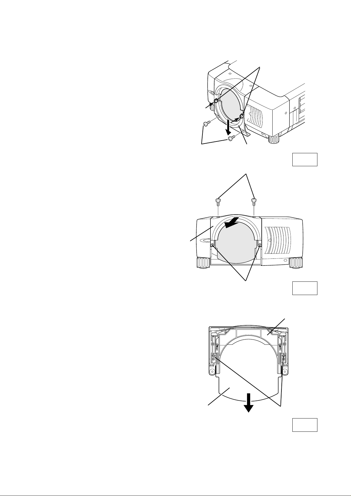
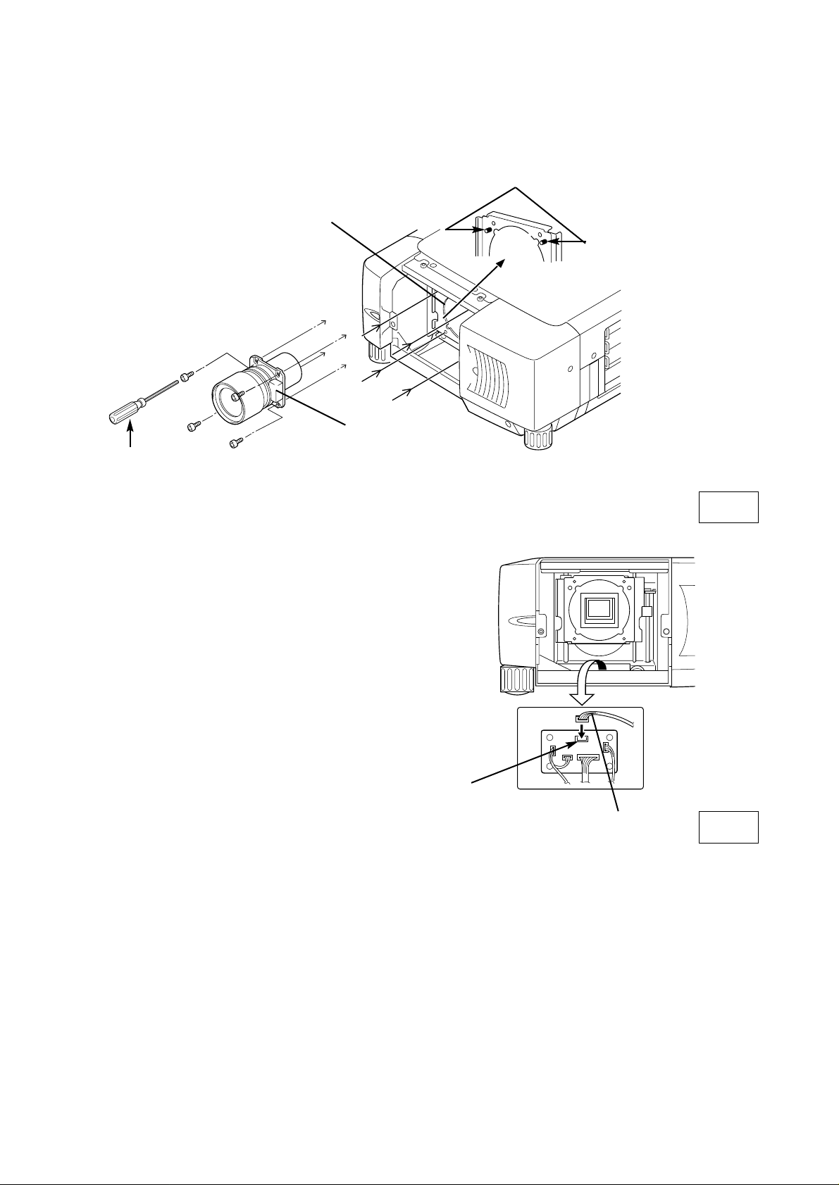
1
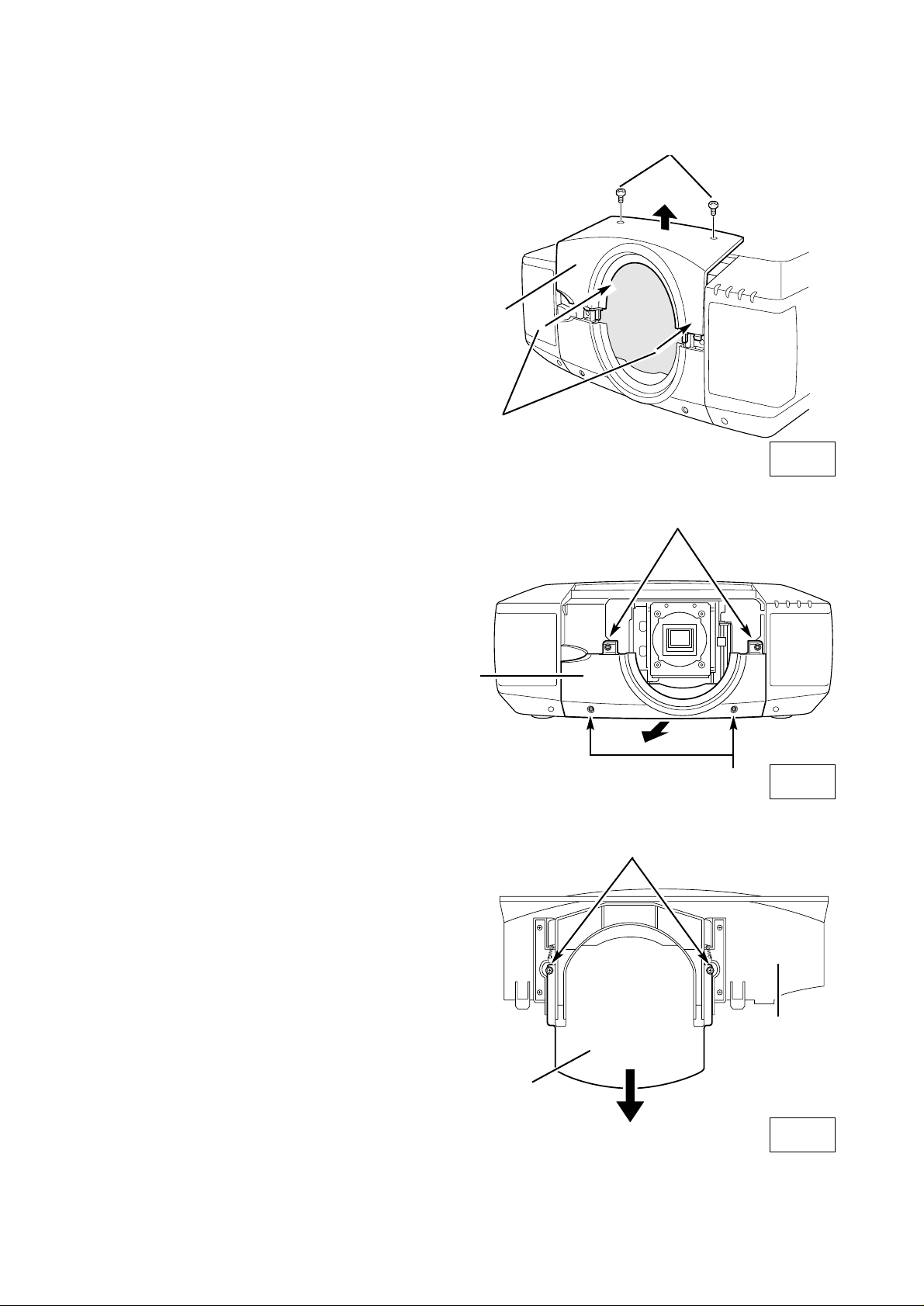
Remove Lower Lens Cover. Remove 2 Screws A.
Push part B and pull Lower Lens Cover down.
(See Fig. 1.)
2
Remove 4 Screws C. Pull Upper Lens Cover
toward front and remove. (See Fig. 2.)
3
Remove 2 Scres D and Cover Plate on the back of
Upper Lens Cover. (See Fig. 3.)
A
C
C
B
Fig-3
Fig-1
Fig-2
UPPER LENS
COVER
COVER PLATE
UPPER LENS
COVER
LOWER LENS
COVER
D
Page 4
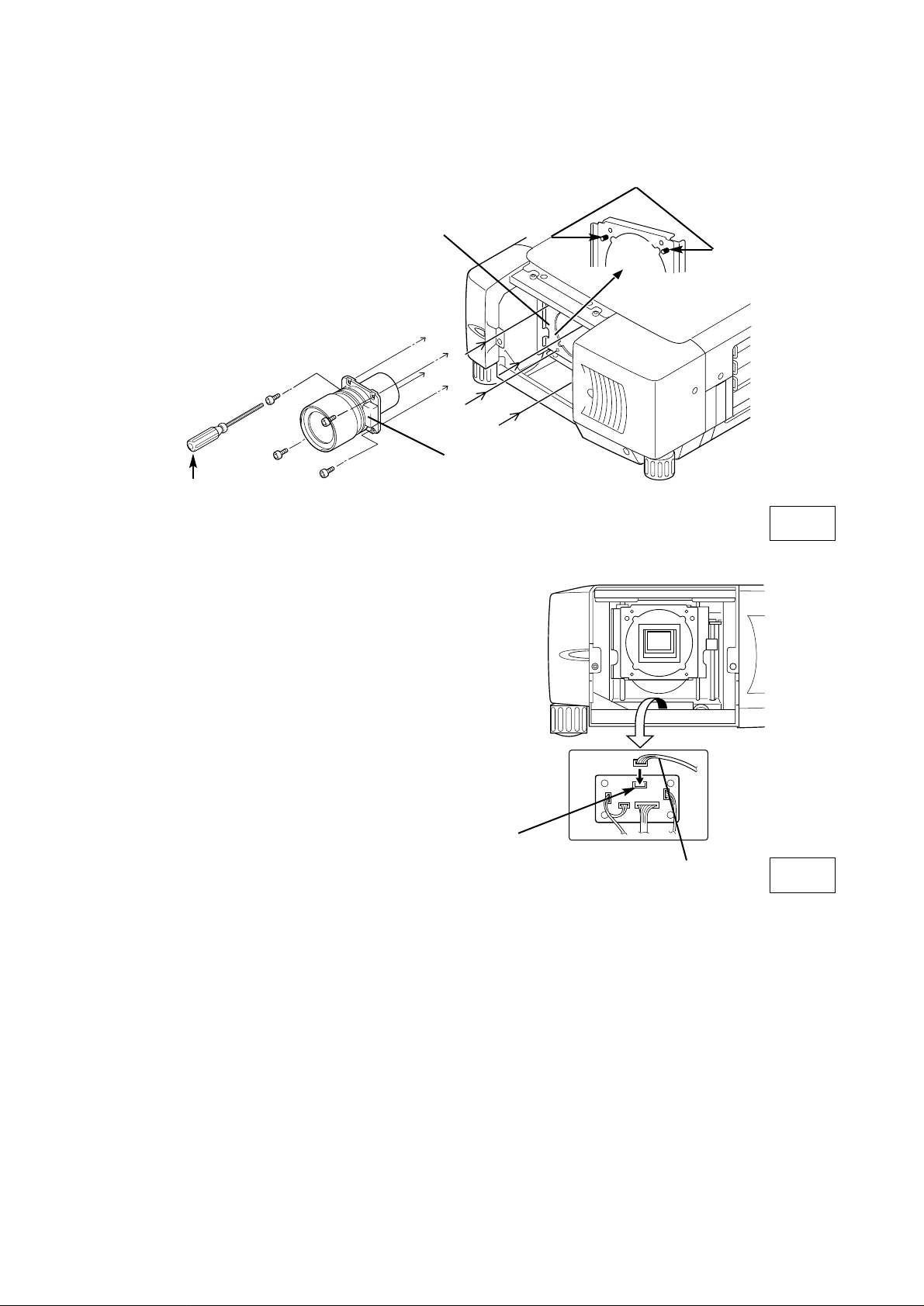
5
Connect Lens Motor Lead to the connector
"K96T" on the circuit board under the lens.
4
Replace Lens Cap on the rear (mounting side) of Projection Lens and mount the lens on Lens
Mouting Bracket with 4 Screws. To mount the lens with Lens Motor on the right. (See Fig. 4.)
GUIDE PIN
Fig-4
DRIVER
IN THE LENS
LOCATE MOTOR
ON RIGHT SIDE
LENS MOUNTING
BLACKET
Fig-5
K96T CONNECTOR
LENS MOTOR LEAD
Part No. (610 275 6029)
-3-
Page 5
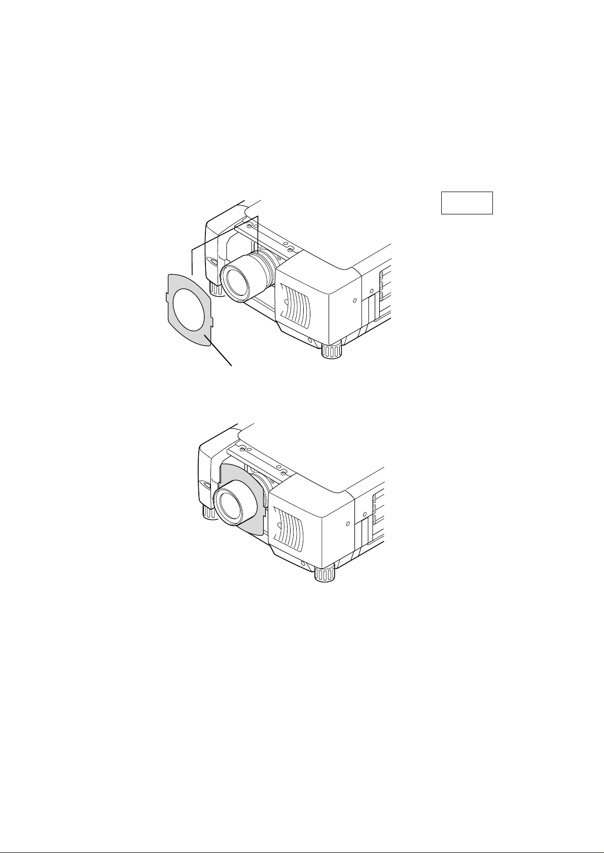
Fig-6
LIGHT BLOCK SHEET
Make sure the sheet figure and put
on proper position.
-4-
6
Use a Light-Block Sheet (provided with projector) corresponding with lens. (Refer to the Type No.
below.) Set Light-Block Sheet through the lens.
Make sure the shape of Light-Block Sheet and be sure to set them as shown in the Fig. 6.
NOTE:
●
Be sure to set a Light-Block Sheet as shown in Fig-6.
●
Make sure the mark (TOP and BACK) on Light-Block Sheet and set them properly.
Use light-block sheet Type No. TYPE FD1 (PART No. 610 290 9258)
Page 6
-5-
7
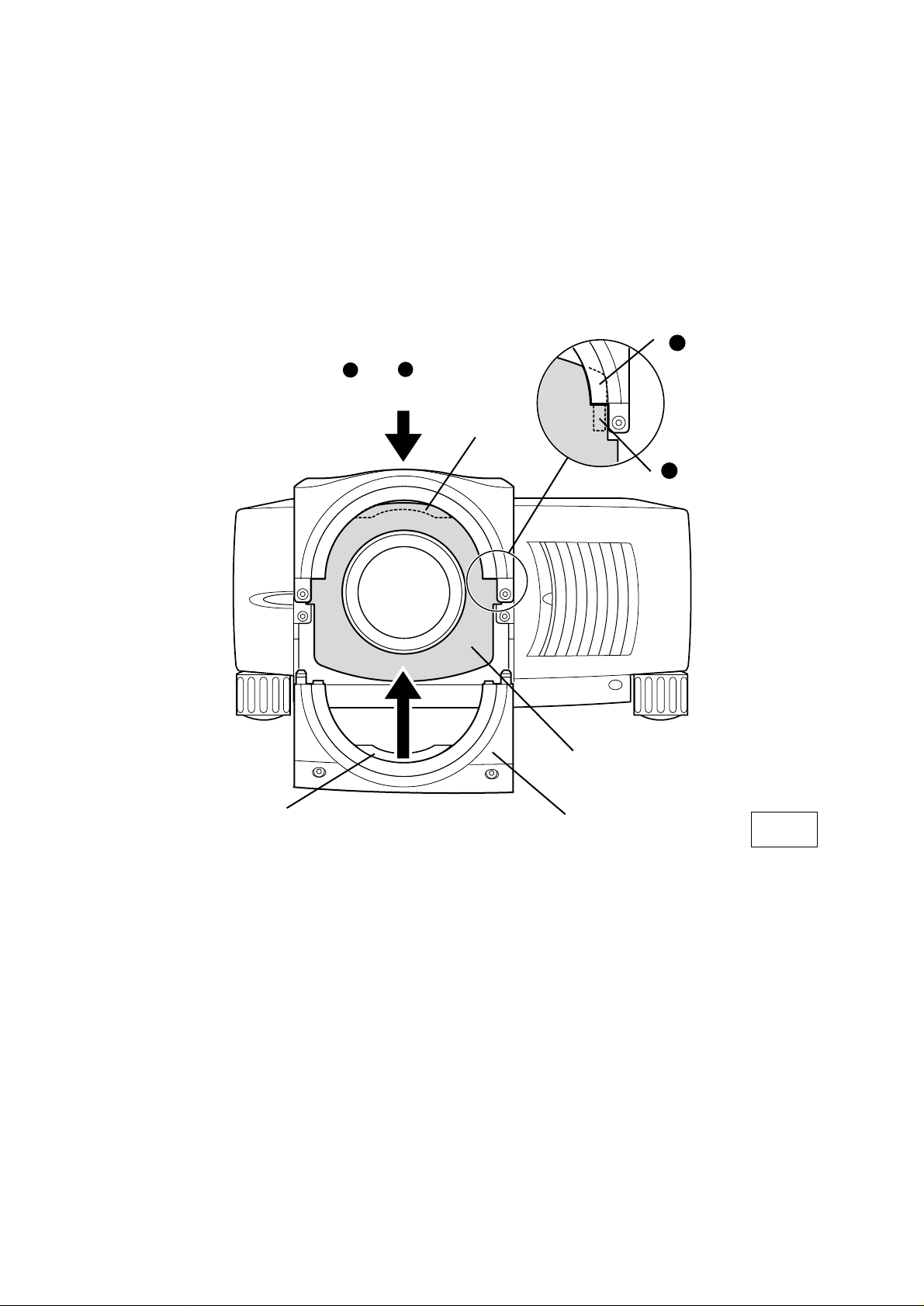
Replace Upper Lens Cover. Slide Light-Block Sheet into the guide of Upper Lens Cover and set
them in front of the flap. (See Fig. 7.) Fix Upper Lens Cover with 4 Screws C. (See Fig. 2.)
8
Replace Lower Lens Cover. Slide Light-Block Sheet into the guide of Lower Lens Cover and set
them in front of the flap. (See Fig. 7.) Fix Lower Lens Cover with 2 Screws A. (See Fig. 1.)
9
Turn the projector on and operate Lens shift, Zoom and Focus fully to check Light-Block Sheet. If
Light-Block Sheet interfere with those operations, check Light-Block Sheet is set properly.
Fig-7
LOWER LENS
COVER
LIGHT-BLOCK
SHEET
Slide into front
of the flap.
FLAP
Slide upper both side of LIGHT BLOCK
SHEET into between and
.
GUIDE
UPPER LENS
COVER
FLAP
1
2
2
1
Page 7
LENS REPLACEMENT AND INSTALLATION PROCEDURE
{Type (2) Cabinet}
-6-
1
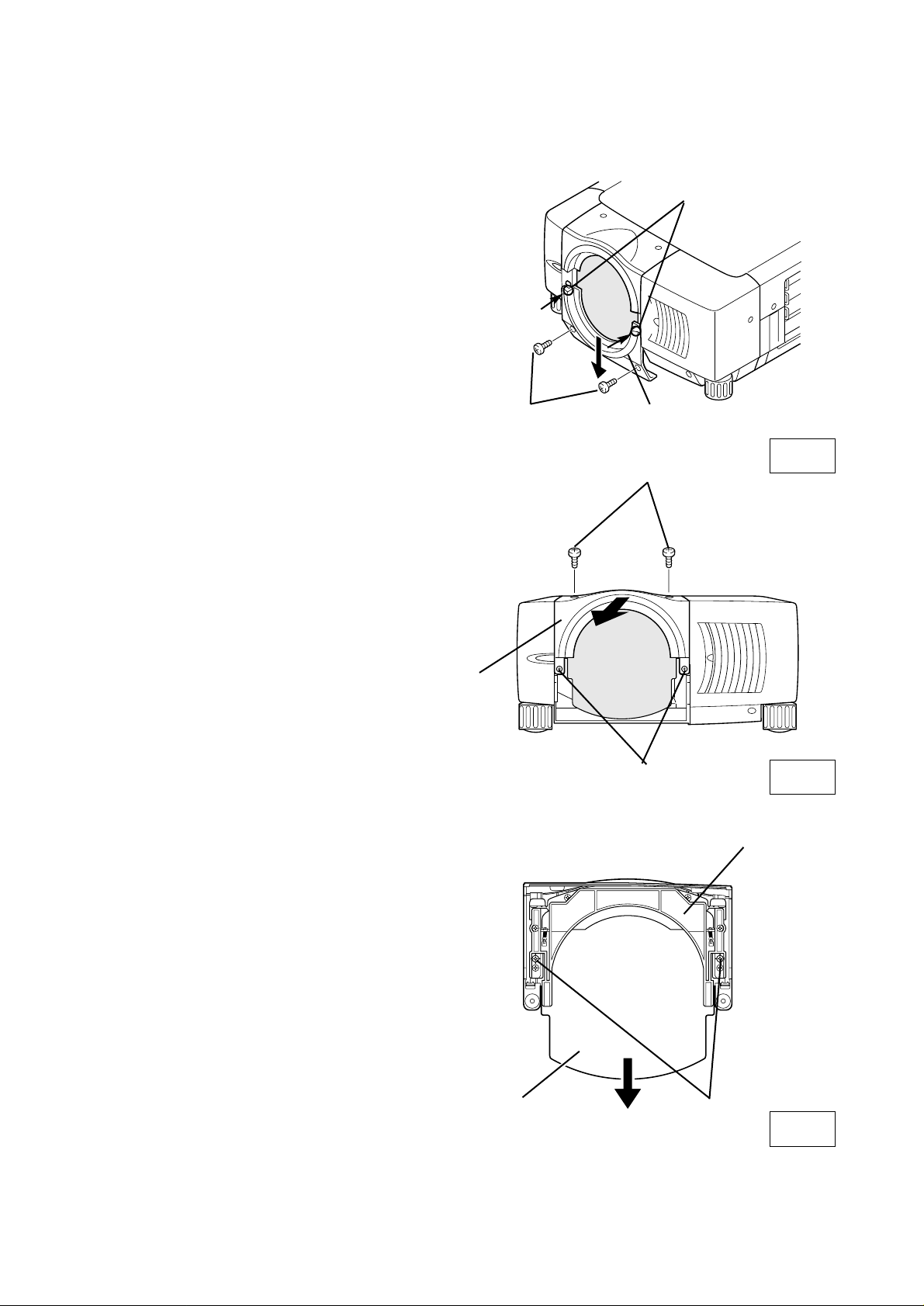
Remove Lens Cover. Remove 2 Screws A. Push
part B and pull Upper Lens Cover up.
(See Fig. 1.)
2
Remove 4 Screws C. Pull Lower Lens Cover
toward front and remove. (See Fig. 2.)
3
Remove 2 Screws D and Cover Plate on the
back of Upper Lens Cover. (See Fig. 3.)
Fig-1
UPPER LENS
COVER
Fig-2
LOWER LENS
COVER
C
COVER PLATE
UPPER LENS
COVER
D
Fig-3
C
B
A
Page 8

-7-
5
Connect Lens Motor Lead to the connector
"K96T" on the circuit board under the lens. Fix
Lens Motor Lead with the lead holder on the circuit board.
Fig-5
LEAD
HOLDER
K96T
CONNECTOR
Fig-4
LENS MOTOR LEAD
LENS MOUNTING
BLACKET
GUIDE PIN
4
Replace Lens Cap on the rear (mounting side) of Projection Lens and mount the lens on Lens
Mouting Bracket with 4 Screws. To mount the lens with Lens Motor on the right. (See Fig. 4.)
LOCATE MOTOR
ON RIGHT SIDE
DRIVER
IN THE LENS
Part No. (610 275 6029)
Page 9

6
Use 2 Light-Block Sheets (provided with projector) corresponding with lens. (Refer to the Type No.
below.) Set 2 Light-Block Sheets through the lens.
Make sure the shape of Light-Block Sheets and be sure to set them as shown in the Fig. 6.
Fig-6
LIGHT BLOCK SHEETS
Make sure the sheets figure and
put on proper position.
-8-
NOTE:
●
Be sure to set each Light-Block Sheets as shown in Fig-6.
●
Make sure the mark (TOP and BACK) on Light-Block Sheets and set them properly.
Use light-block sheets Type No. TYPE FC1 (PART No. 610 284 2500)
TYPE FC2 (PART No. 610 284 2494)
Page 10

-9-
7
Replace Lower Lens Cover. Slide Light-Block Sheets into the guide of Lower Lens Cover and set
them in front of the flap. (See Fig. 7.) Fix Lower Lens Cover with 4 Screws C. (See Fig. 2.)
8
Replace Upper Lens Cover. Slide Light-Block Sheets into the guide of Upper Lens Cover and set
them in front of the flap. (See Fig. 7.) Fix Upper Lens Cover with 2 Screws A. (See Fig. 1.)
9
Turn the projector on and operate Lens shift, Zoom and Focus fully to check Light-Block Sheets. If
Light-Block Sheets interfere with those operations, check Light-Block Sheets are set properly.
Fig-7
LOWER LENS
COVER
UPPER LNES
COVER
LIGHT-BLOCK
SHEETS
FLAP
Slide into front
of the flap.
Slide into front
of the flap.
FLAP
Slide upper both side of LIGHT BLOCK
SHEETS into between and
.
CABINET
GUIDE
1
2
1
2
Page 11

キャビネットの形状 (2)6ページ参照
1AA6P1P2987-- (IDAJ)
液晶プロジェクターレンズ
品番 LNS-S03
レンズ交換・取付作業手順書
ご注意:レンズを取り付けるまえに
レンズはご使用になるプロジェクターのキャビネットの形状により、取付部品、お
よび取付方法が異なります。取り付けるまえにキャビネットの形状をよくお確かめ
のうえ、キャビネットに合った取付作業手順にしたがい、正しくご使用ください。
レンズは液晶プロジェクターに適合した正しい品番のものをお使いください。詳し
くはカタログ、または販売店でお確かめください。
キャビネットの形状と取付作業手順
キャビネットの形状により取付作業手順が異なります。下図を参照のうえ、正しい作業
手順で行ってください。
キャビネットの形状 (1)2ページ参照
※上記形状以外の機種へのご使用については取扱販売店へご相談ください。
Page 12

レンズの取り付け、または交換のあとに、お使いにならない部品が残る場合があります。
これらの部品は後日必要となる場合がありますので、大切に保管してください。
※説明文中の図は実際のものと異なる場合があります。
取り付け作業上の注意
●レンズの取り付け、交換作業はサービス技術員が行ってください。
●レンズの取り付け、交換作業はこの作業手順書にしたがい、正しく行ってくだ
さい。
●レンズにはレンズ保護のためのキャップが付いています。レンズを取り付ける
まえに、かならずキャップをはずしてください。
●レンズの取り付け、取り外しのとき、レンズの表面を手でさわったり傷を付け
たりしないようご注意ください。
レンズを取り付けたあと、レンズカバーを取り付けるまえに、つぎの点検を行って
ください。
1. レンズが4本のスクリューでしっかり固定されているか。
2. 外れている部品はないか。
安全のため、必ずつぎの点検と確認を行ってください。
部品明細
梱包には以下の部品が入っています。
・レンズ本体 1個
・専用ドライバー 1本
-1-
Page 13
レンズの交換と取り付けかた {キャビネット形状 (1)の場合}
-2-
1
レンズカバー下のスクリューA(2本)を外し、
B部を矢印の方向に押し、レンズカバー下を下
方へ引いて外します。(図-1参照)
2
スクリューC(4本)を外し、レンズカバー上
を手前に引いて外します。(図-2参照)
3
レンズカバー上裏面のスクリューD(2本)を外
し、カバープレートを外します。(図-3参照)
図-1
レンズカバー下
A
図-2
レンズカバー上
C
C
B
D
図-3
レンズカバー上
カバ−プレ−ト
Page 14
-3-
5
レンズモーターリードの接続を行います。レン
ズモーターのコネクターをレンズ下にあるプリ
ント基板のコネクターK96Tに接続します。
(図-5参照)
図-5
K96T
レンズモーターリード
4
レンズ後面についているレンズ保護キャップを外し、レンズをプロジェクターのレンズマウント
ブラケットにレンズに付属の4本のスクリューで取り付けます。(モーターを右側にして取り付け
ます。)(図-4参照)
ガイドピン
レンズマウント
ブラケット
レンズモーターを
右側にします。
図-4
レンズに付属
のドライバー
品番 (6102756029)
Page 15

6
プロジェクターに同梱されている遮光プレートをレンズに通して取り付けます。(遮光プレート
にTypeNo.が表示がされています。)
プレートを下図の方向に取り付けてください。(図-6参照)
・ 形状を確認し、前後を間違えない様注意ください。
・ 遮光プレートには取り付け方向が表示されています。THISSIDEBACKを後方に、TOPを上
側に取り付けます。
使用する遮光プレートのTypeNo.TYPEFD1(PARTNo.6102909258)
図-6
遮光プレート
形状を確認のうえ、方向を間違え
ない様注意ください。
-4-
Page 16

7
レンズカバー上を取り付けます。遮光プレートをレンズカバー上に差し込んで取り付けます(遮
光プレートカバーのガイドとレンズカバー上の間に差し込みます。遮光プレートがカバー上のフ
ラップ前面になる様に取り付けてください。(図7-参照)レンズカバー上のスクリューの取り付
けは図-2を参照ください。
8
レンズカバー下を取り付けます。遮光プレートカバーのガイドとキャビネットの間に差し込みま
す。遮光プレ−トはフラップの前面になる様に取り付けます。(図7-参照)
レンズカバ−下を2本のスクリューで取り付けます。レンズカバー下のスクリューの取り付けは
図-1を参照ください。
9
プロジェクターに電源を入れ、レンズシフトを上下に、またズーム・フォーカスを動かし、遮
光プレートがレンズと共に正しく動くか確認します。遮光プレートがレンズの動きを妨げてい
ればもう一度遮光プレートが正しく取り付けられているか確認ください。
遮光プレート上部の両サイドを と の
間に差し込みます。
ガイド
レンズカバー上
遮光プレート
フラップの前面へ
差し込む
フラップ
フラップ
レンズカバー下
図-7
-5-
2
1
1
2
Page 17

レンズの交換と取り付けかた {キャビネット形状 (2)の場合}
-6-
1
キャビネット前面のスクリューA(2本)を外
し、B部を矢印の方向に押し、レンズカバー上
を上方へ引いて外します。(図-1参照)
2
スクリューC(4本)を外し、レンズカバー下
を手前に引いて外します。(図-2参照)
3
レンズカバー上裏面のスクリューD(2本)を
外し、カバープレートを外します。
(図-3参照)
図-1
レンズカバー上
A
図-2
レンズカバー下
C
カバ−プレ−ト
レンズカバー上
D
図-3
B
B
Page 18

5
レンズモーターリードの接続を行います。レン
ズモーターのコネクターをレンズ下にあるプリ
ント基板のコネクターK96Tに接続します。
モーターリード線をプリント基板のリードホ
ルダーで固定します。(図-5参照)
図-5
リードホルダー
K96T
図-4
レンズモーターリード
4
レンズ後面についているレンズ保護キャップを外し、レンズをプロジェクターのレンズマウント
ブラケットにレンズに付属の4本のスクリューで取り付けます。(モーターを右側にして取り付け
ます。)(図-4参照)
レンズに付属
のドライバー
レンズモーターを
右側にします。
レンズマウント
ブラケット
ガイドピン
品番 (6102756029)
-7-
Page 19

-8-
6
プロジェクターに同梱されている遮光プレートをレンズに通して取り付けます。(遮光プレート
にTypeNo.が表示がされています。)
遮光プレートは2枚使用します。各プレートを下図の方向に取り付けてください。(図-6参照)
・ 形状を確認し、前後を間違えない様注意ください。
・ 遮光プレートには取り付け方向が表示されています。THISSIDEBACKを後方に、TOPを上
側に取り付けます。
図-6
遮光プレート
形状を確認のうえ、方向を間違え
ない様注意ください。
使用する遮光プレートのTypeNo.TYPEFC1(PARTNo.6102842500)
TYPEFC2(PARTNo.6102842494)
Page 20

-9-
7
レンズカバー下を取り付けます。遮光プレートをカバー下に差し込んで取り付けます。
遮光プレートがカバー下のフラップ前面になる様に取り付けてください。(図7-参照)レンズカ
バー下のスクリューの取り付けは図-2を参照ください。
8
レンズカバー上を取り付けます。遮光プレートをカバーのガイドとキャビネットの間に差し込み
ます。遮光プレートはフラップの前面になる様に取り付けます。(図-7参照)
上面カバーを2本のスクリューで取り付けます。スクリューの取り付けは、図-1を参照くださ
い。
9
プロジェクターに電源を入れ、レンズシフトを上下左右に、またズーム・フォーカスを動かし、
遮光プレートがレンズと共に正しく動くか確認します。遮光プレートがレンズの動きを妨げて
いればもう一度遮光プレートが正しく取り付けられているか確認ください。
図-7
レンズカバー下
レンズカバー上
遮光プレート
フラップ
フラップの前面へ
差し込む
フラップの前面へ
差し込む
フラップ
遮光プレート上部の両サイドを と の
間に差し込みます。
キャビネット上
ガイド
2
1
1
2
Page 21

documentation manual, user maintenance, brochure, user reference, pdf manual
This file has been downloaded from:
User Manual and User Guide for many equipments like mobile phones, photo cameras, monther board, monitors, software, tv, dvd, and othes..
Manual users, user manuals, user guide manual, owners manual, instruction manual, manual owner, manual owner's, manual guide,
manual operation, operating manual, user's manual, operating instructions, manual operators, manual operator, manual product,
 Loading...