


PARTS LIST
Following parts are contained in the packing.
· LENS
· LENS MOUNTING SCREWS
· DRIVER
· LIGHT-BLOCK SHEET
NOTES ON LENS INSTALLATION
LCD PROJECTOR LENS
MODEL NO. LNS-M01
LNS-S01
Lens installation should be performed by the qualified service personnel.
It should be followed by this procedure precisely.
Before attempt to install the lens, confirm the model number (both the LCD
projector and the lens) and use the proper lens.
If you have any questions, contact to the dealers.
Following checks and confirmations should be taken for safety.
Check the following things by the time of the cabinet assembly after the
lens installation.
1. Confirm the lens is securely fixed by 4 screws.
2.Wiring must not be tangled in the gear of the lens motor or the other
mechanical part.
3.There is no missing part, or no loosing mounting part.
1AA6P1P1980-- (ICPP)
1 piece
6 screws (2 for spare)
1 piece
1 sheet
LENS REPLACEMENT AND
INSTALLATION PROCEDURE
LENS REPLACEMENT AND INSTALLATION PROCEDURE
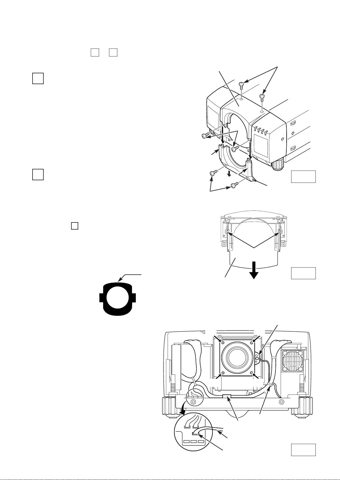
Remove screws A (2 screws).
Pull down the lower lens cover while pushing
the part D, then remove it.
Remove screws B (2 screws).
Remove screws C (2 screws) and remove
upper lens cover.
1
4
Perform the steps to for lens replacement and installation.
1
1.
2.
A
Fig-1
Fig-2
● IN CASE OF MODEL WITHOUT LENS
Remove 2 screws and pull down the plate.
2
3.
4.
UPPER LENS COVER
LOWER LENS COVER
C
B
D
D
COVER PLATE
REMOVE THE LENS COVER. (See figure-1)
(At the step , insert the light-block sheet in the same
position as the removed cover plate has been placed.
Two screws are not used.)
Use the light-block sheet included with lens.
Set the light-block sheet, so that the large rounder side
is set over the lens.
4
REMOVE THE COVER PLATE OF THE LENS COVER. (See figure-2)
LENS MOT OR LEAD
CONNECTOR “ K16B”
(D)
(D)
(D)
(D)
B
LENS MOT OR
Fig-3
❋Figure shown inside of the cabinet.
REMOVE THE LENS. (See figure-3.)
1. Remove the connector “K16B” of the
circuit board.
2. Loosen the A, B wire holder and
remove the lens motor lead.
3. Remove screws D (4 screws) which
fastens the lens and remove the lens.
● IN CASE OF MODEL WITH LENS
A
Set the light-block
sheet, so that the
large rounder side
is set over the lens.
SCREWS
WIRE HOLDER
 Loading...