

Page 1
SERVICE MANUAL
INDUSTRIAL LCD MONITOR
LMU-TK15A3 (GENERAL)
(GENERAL)
LMU-TK15A3TC
(With Touch Screen)
(GENERAL)
LMU-TK15A3TS
(With Touch Screen)
PRODUCT CODE NO.
LMU-TK15A3 1 938 102 77
LMU-TK15A3TC 1 938 102 78
LMU-TK15A3TS 1 938 102 83
REFERENCE No. SM920018
Page 2

_ _
1
INDEX
Page
PRECAUTIONS ---------------------------------------------------------------------------------- 2
1, MAIN SPECIFICATION --------------------------------------------------------------------- 3,4
2, TROUBLESHOOTING ----------------------------------------------------------------------- 5,6
3, MAINTENANCE
3-1 LUM-TK15A3 ------------------------------------------------------------------------------ 7
3-2 LUM-TK15A3TC -------------------------------------------------------------------------- 8
3-3 LUM-TK15A3TS -------------------------------------------------------------------------- 9
4, BLOCK DIAGRAM ---------------------------------------------------------------------------- 10
5, CONNECTION DIAGRAM
5-1 LUM-TK15A3 ------------------------------------------------------------------------------ 11
5-2 LUM-TK15A3TC -------------------------------------------------------------------------- 12
5-3 LUM-TK15A3TS --------------------------------------------------------------------------
6, TABLE OF SIGNAL NAME ------------------------------------------------------------------ 14,15
13
7, EXPLODED VIEW AND PARTS LIST
7-1 Exploded View
7-1-1 LUM-TK15A3 ------------------------------------------------------------------------7-1-2 LUM-TK15A3TC ---------------------------------------------------------------------
7-1-3 LUM-TK15A3TS ---------------------------------------------------------------------
16
17
18
7-2 Parts List
7-2-1 LUM-TK15A3 ------------------------------------------------------------------------7-2-2 LUM-TK15A3TC ---------------------------------------------------------------------
7-2-3 LUM-TK15A3TS ---------------------------------------------------------------------
19
20
21
8, APPENDIX -------------------------------------------------------------------------------------- 22
Refer to the separate volume User’s Manual and CD-ROM
that included for instruction.
Page 3

_ _
2
PRECAUTIONS
Placement precautions
Avoid placing the unit in humid or dusty places, or where it will be exposed to excessive heat
(direct sunlight, heaters, etc.)
Do not step on or set anything on the AC cord.
DAMAGE TO THE AC CORD IS A SAFETY RISK AND CAN CAUSE A FIRE.
Do not connect the unit to the same AC as outlet with appliances that generate large amounts of
interference (such as heaters with thermostats, appliances with motors, etc.). It is best to use a
completely separate electrical outlet.
Keep the unit away from water. If water accidentally enters the unit, unplug the AC power cord
immediately. DO NOT PLUG IN THE UNIT AGAIN.
Handling precautions
Avoid bending, kinking or damaging the AC power cord.
Never insert or remove the power cord with wet hands. Also, be sure to hold cord by the plug when
removing it from the outlet.
Do not remove any parts that are held in place with screws. (The unit does not contain any user
serviceable items.)
Maintain standard room temperature (5
o
C to 35 oC, or 41oF to 95 oF) during use. Do not subject the
unit to shock or vibration. Do not move the unit while it is in use.
A rapid increase in room temperature in cool weather can cause condensation to from inside the unit.
If this occurs, wait at least 15 minutes after turning the unit on before attempting to operate it.
Page 4
_ _
3
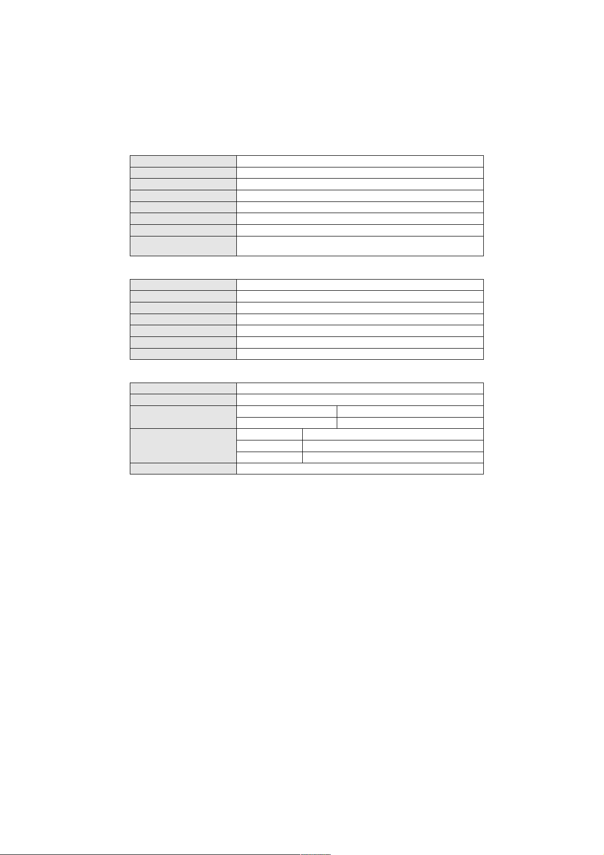
1. MAIN SPECIFICATION
Dimensions 384 (W) x 308 (H) x 46 (D) mm
Weight 3.7kg
Operating Conditions Operating Temperature: 5°C to 40°C
Humidity: 30% to 85% RH (no condensation)
Power Supply/AC Adapter Model Name: GI40-US1225
Input: 115-240VAC 1.0A-0.55A, 50-60Hz
Output: DC 12V 2.5A
Power Consumption 28W (5W in Energy Saving mode)
Liquid Crystal Panel TFT
Display Size 15.0''
Pixel Configuration 1,024 x 768
Pixel Pitch 0.297 x 0.297 mm
Brightness 250 cd/m
2
Response Time 40 ms
Contrast 350 : 1 typ.
Angle of Visibility Up 50, Down 55, Right 60, Left 60 degrees
(contrast ratio of less than 10)
Note : To improve this LCD monitor’s performance level, its specifications and
appearance are subject to change without notice.
LCD
Video
Physical
Vertical signal 56 - 75Hz
Horizontal signal 31.4 - 60.2kHz
Video Signal Analog RGB 75ohm 0.7Vp-p
No. of Colors 16.77 million
OSD Language English, German, French, Spanish
Plug & Play VESA DDC1, DDC2B
Power Management VESA DPMS
LMU-TK15A3
Page 5
_ _
4
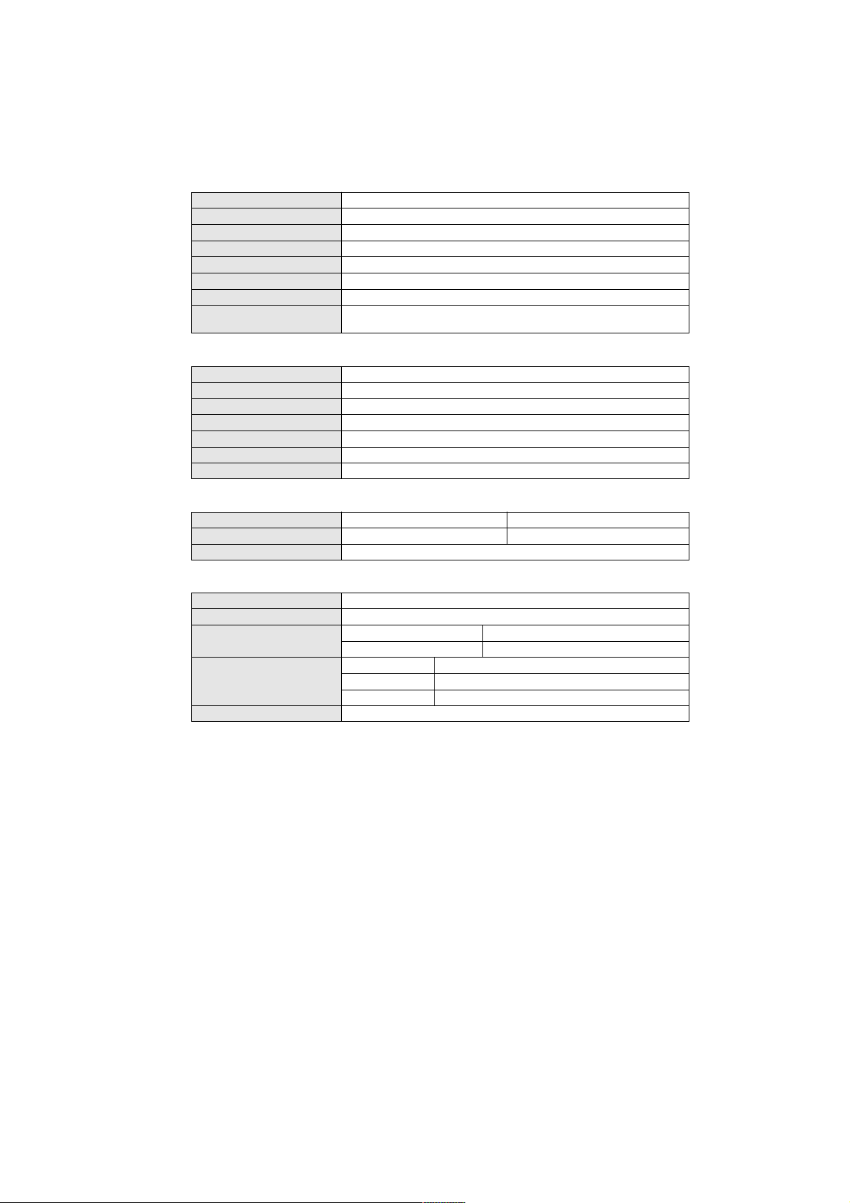
Dimensions 385 (W) x 309 (H) x 54 (D) mm
Weight 4.2kg
Operating Conditions Operating Temperature: 5°C to 40°C
Humidity: 30% to 85% RH (no condensation)
Power Supply/AC Adapter Model Name: GI40-US1225
Input: 115-240VAC 1.0A-0.55A, 50-60Hz
Output: DC 12V 2.5A
Power Consumption 30W (5W in Energy Saving mode)
Liquid Crystal Panel TFT
Display Size 15.0''
Pixel Configuration 1,024 x 768
Pixel Pitch 0.297 x 0.297 mm
Brightness 250 cd/m
2
Response Time 40 ms
Contrast 350 : 1 typ.
Angle of Visibility Up 50, Down 55, Right 60, Left 60 degrees
(contrast ratio of less than 10)
Note : To improve this LCD monitor’s performance level, its specifications and
appearance are subject to change without notice.
LCD
Video
Physical
Vertical signal 56 - 75Hz
Horizontal signal 31.4 - 60.2kHz
Video Signal Analog RGB 75ohm 0.7Vp-p
No. of Colors 16.77 million
OSD Language English, German, French, Spanish
Plug & Play VESA DDC1, DDC2B
Power Management VESA DPMS
Touch Screen
Type Capacitive (LMU-TK15A3TC) Surface Wave (LMU-TK15A3TS)
Electrical Resolution 10bit (1,024 x 1,024) 0.86 x 0.86 mm
Communication Bi-directional asynchronous RS-232C serial communication
LMU-TK15A3TC/LMU-TK15A3TS
Page 6

_ _
5
Check the following for troubles of LCD monitor.
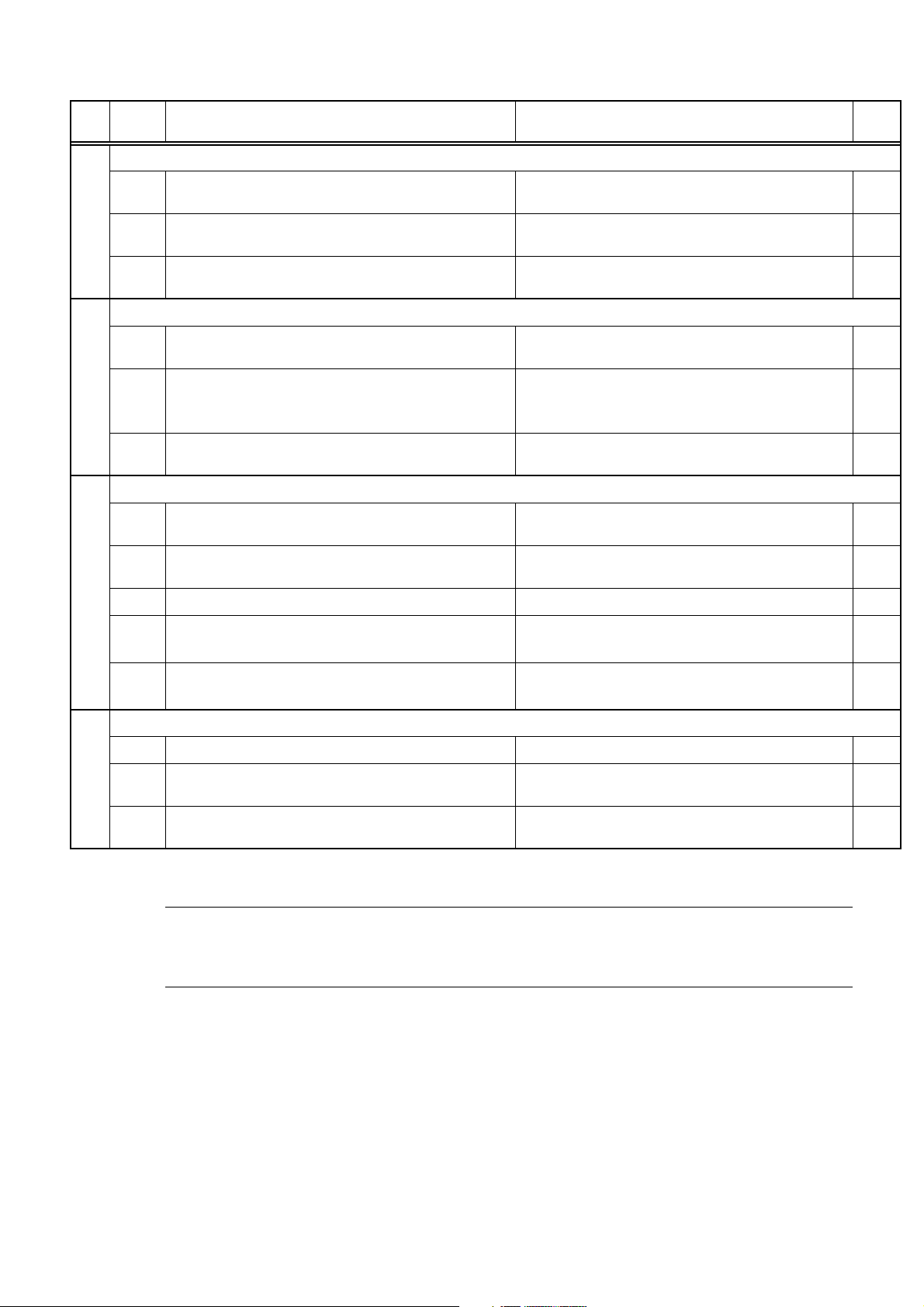
2. TROUBLESHOOTING
Symptom
No. Check Points Treatments Class
1
No Picture with Back light OFF
1 Is the Power "ON" to a LCD Monitor ?
2 Is the Power "ON" to a Computer ? Check the Power for a Computer A
3 Is a signal cable connected securely ? Check the connection of a signal cable A
4 Is a computer standing by ?
Disconnected a signal cable ? or Bent a
5
terminal pin ?
6 Is an AC Adapter defective? Replace an AC Adapter with the new one C
Is the wire harness between main PCB and
7
LCD module secured firmly ?
Is the wire harness between LCD module and
8
DC/DC Comnv. secured firmly ?
Is the wire harness between DC IN PCB and
9
DC/DC Conv. PCB secured firmly ?
Is the wire harness between main PCB and DC
10
IN PCB secured firmly ?
11 Is the LCD module defective ? Replace a LCD module with the new one C
Check AC outlet, AC cord, DC Jack and
Power switch for a LCD monitor
Be out of standing by condition, by operating
to a computer
Ensure the connection of a signal cable B
Check the connection of wire harness C
Check the connection of wire harness C
Check the connection of wire harness C
Check the connection of wire harness C
A
A
12 Is the Inverter block on LCD module defective ? Replace a LCD module with the new one C
13 Is the DC/DC Conv. PCB defective ?
14 Is the display circuit on main PCB defective ? Replace the main PCB with the new one C
Is the Power Supply circuit on main PCB
15
defective ?
No Picture with Back light ON
2
1 Is a screen saver programming running ?
Is the computer’s signal timing not agreeable to
2
the LCD’s specification ?
Is the Image Processing circuit on main PCB
3
defective ?
White/Grey on whole screen(Nothing on screen)
3
Is the wire harness between main PCB and
1
LCD module secured firmly ?
2 Is the LCD module defective ? Replace a LCD module with the new one C
Is the Image Processing block circuit on main
3
PCB defective ?
Replace a DC/DC Conv. PCB with the new
one
Replace the main PCB with the new one C
Press any key or touch the mouse, to end the
screen saver program
Adjust the computer’s signal timing, if
possible
Replace the main PCB with the new one C
Ensure the connection of wire harness C
Replace the main PCB with the new one C
C
A
B
A It is possible to treated by end-user
B It might be possible to treat by end-user in some case.
C It must be treated by Professional Technical Staff
Page 7
_ _
6
No. Check Points Treatments Class
4
1
Is the wire harness between inverter and a LCD
module secured firmly ?
Ensure the connection of a wire harness C
2
Is the wire harness between one of inverters
and main PCB secured firmly ?
Ensure the connection of a wire harness C
3 Is the display circuit on main PCB defective ? Replace the main PCB with the new one C
5
1
Is the adjustment for screen performed
correctly ?
Adjust the screen correctly A
2
Is the output level on image from a computer
not agreeable to LCD’s specification ?
Check the specification of a computer B
3 Is the size of screen set correctly ?
Set the size of screen again(refer to User’s
Manual for computer)
A
6
1
Is the adjustment for screen performed
correctly ?
Adjust the screen correctly A
2 Is a signal cable connected securely ? Check the connection of a signal cable A
3 Is a sigil cable extended ? Don’t extend a signal cable A
4
Is the output level on image from a computer
not agreeable to LCD’s specification ?
Check the specification of a computer B
5
Is the Image Processing circuit on main PCB
defective ?
Replace the main PCB with the new one C
7
1 Is a signal cable connected securely ? Check the connection of a signal cable A
2
Is the connection between main PCB and a
LCD module securely ?
Ensure the connector of wire harness C
3
Is the Image Processing circuit on main PCB
defective ?
Replace the main PCB with the new one C
Screen’s display range is incorrect
Screen is distorted
Part of colors (R/G/B) is not displayed. Black line appears in vertically
Dark screen
Symptom
A It is possible to treated by end-user
B It might be possible to treat by end-user in some case.
C It must be treated by Professional Technical Staff
Page 8

_ _
7
3-1 LMU-TK15A3
3. MAINTENANCE
Disassembling the major components
(1) Cabinet
1. Unscrew to secure the cabinet (8-position)
2. Pull the cabinet upward to remove it
(2) LCD Panel
1. Unscrew to secure the LCD panel (4-position)
2. Pull the LCD panel up, and pull two connectors out from inverter unit
3. Disconnect two cables from the Main PCB
(3) Main PCB
1. Pull the RGB signal cable out
2. Unscrew to secure the Main PCB (5-position)
3. Disconnect the cables on the Main PCB (6-position)
/ Two connectors from the LCD module
/ One connector from the VR PCB
/ One connector from the DC-IN PCB
/ One connector from the Inverter PCB
/ One connector from the CN PCB
4. Unscrew to secure the bracket for RGB Connector (2-position)
(4) VR PCB
1. Unscrew to secure the VR PCB (2-position)
2. Disconnect the cable from the Main PCB
(5) DC-IN PCB
1. Unscrew to secure the DC-IN PCB (2-position)
2. Disconnect two cables, one is from power switch and another one is from the Main PCB
(6) CN PCB
1. Unscrew to secure the bracket for CN PCB (2-position)
2. Disconnect the cable from the Main PCB
(7) DC-AC Inverter
1. Unscrew to secure the DC-AC Inverter (4-position)
2. Disconnect the cable from the Main PCB
Page 9

_ _
8
3-2 LMU-TK15A3TC
Disassembling the major components
(1) Cabinet
1. Unscrew to secure the cabinet (8-position)
2. Pull the cabinet upward to remove it
(2) LCD Panel
1. Unscrew to secure the LCD panel (4-position)
2. Pull the LCD panel up, and pull two connectors out from inverter unit
3. Disconnect two cables from the Main PCB
(3) Main PCB
1. Pull the RGB signal cable out
2. Unscrew to secure the Main PCB (5-position)
3. Disconnect the cables on the Main PCB (6-position)
/ Two connectors from the LCD module
/ One connector from the VR PCB
/ One connector from the DC-IN PCB
/ One connector from the Inverter PCB
/ One connector from the CN PCB
4. Unscrew to secure the bracket for RGB Connector (2-position)
(4) VR PCB
1. Unscrew to secure the VR PCB (2-position)
2. Disconnect the cable from the Main PCB
(5) DC-IN PCB
1. Unscrew to secure the DC-IN PCB (2-position)
2. Disconnect two cables, one is from power switch and another one is from the Main PCB
(6) CN PCB
1. Unscrew to secure the bracket for CN PCB (2-position)
2. Disconnect the cable from the Main PCB
(7) DC-AC Inverter
1. Unscrew to secure the DC-AC Inverter (4-position)
3. Disconnect the cable from the Main PCB
(8) Touch Controller
1. Unscrew to secure the Touch Controller (2-position)
2. Disconnect two cables from Touch Controller
Page 10

_ _
9
3-3 LMU-TK15A3TS
Disassembling the major components
(1) Cabinet
1. Unscrew to secure the cabinet (8-position)
2. Pull the cabinet upward to remove it
(2) LCD Panel
1. Unscrew to secure the LCD panel (4-position)
2. Pull the LCD panel up, and pull two connectors out from inverter unit
3. Disconnect two cables from the Main PCB
(3) Main PCB
1. Pull the RGB signal cable out
2. Unscrew to secure the Main PCB (5-position)
3. Disconnect the cables on the Main PCB (6-position)
/ Two connectors from the LCD module
/ One connector from the VR PCB
/ One connector from the DC-IN PCB
/ One connector from the Inverter PCB
/ One connector from the CN PCB
4. Unscrew to secure the bracket for RGB Connector (2-position)
(4) VR PCB
1. Unscrew to secure the VR PCB (2-position)
2. Disconnect the cable from the Main PCB
(5) DC-IN PCB
1. Unscrew to secure the DC-IN PCB (2-position)
2. Disconnect two cables, one is from power switch and another one is from the Main PCB
(6) CN PCB
1. Unscrew to secure the bracket for CN PCB (2-position)
2. Disconnect the cable from the Main PCB
(7) DC-AC Inverter
1. Unscrew to secure the DC-AC Inverter (4-position)
2. Disconnect the cable from the Main PCB
(8) Touch Controller
1. Unscrew to secure the Touch Controller (4-position)
2. Disconnect three cables from Touch Controller
Page 11

_ _
10
_
4. BLOCK DIAGRAM
Main Board
DDC
RED
BLUE
GREEN
Hsync
IRQ
HCLK
HFS
HDATA
EEPROM
Micro
Controller
Video Controller ASIC
Host
Interface
ADC
Interface
Generator
ROM
Panel
Clock
OSD Buttons
R・G・B Even Data
R・G・B B Odd Data
ODCK
LCD
DE
15inch
XGA
TFT
LCD
Panel
Inverter
Vsync
RS232C
DC/DC Converter
Power Supply
Micro
Controller
TOUCH CONTROLLER
ROM
AMP
A/D Conv.
Touch Senset Interface
NVRAM
Micro Controller Interface
Touch Control Board (for LMU-TK15A3TC, LMU-TK15A3TS only)
Rotally
Volume
Touch Senser
Page 12

_ _
11
5. CONNECTION DIAGRAM
5-1 LUM-TK15A3
Inverter
P.C.B
CN3
123
V_HIGH
V_LOW
123
30
CN2
CN1
29
28
27
26
25
24
23
22
21
20
19
18
17
16
15
14
13
12
11
10
9
8
7
6
5
4
3
2
1
45
44
43
42
41
40
39
38
37
36
35
34
33
32
31
30
29
28
27
26
25
24
23
22
21
20
19
18
17
16
15
14
13
12
11
10
9
8
7
6
5
4
3
2
1
CN4
TFT 15.0-inch Liquid Crystal
Display
123
V_HIGH
123
CN3
CN2
V_LOW
CN1
12345
GND
VIN
PPWR
N.C.
CONT
12345
30
RE0
29
RE1
28
RE2
27
RE3
26
GND
25
RE4
24
RE5
23
RE6
22
RE7
21
GND
20
GE0
19
GE1
18
GE2
17
GE3
16
GND
15
GE4
14
GE5
13
GE6
12
GE7
11
GND
10
BE0
9
BE1
8
BE2
7
BE3
6
GND
5
BE4
4
BE5
3
BE6VR2
2
BE7
1
GND
VCC
VCC
RO0
RO1
RO2
RO3
GND
RO4
RO5
RO6
RO7
GND
GO0
GO1
GO2
GO3
GND
GO4
GO5
GO6
GO7
GND
BO0
BO1
BO2
BO3
GND
BO4
BO5
BO6
BO7
GND
GND
N.C.
GND
N.C.
GND
DEVSYNC
GND
DCLK
GND
CN201
45
44
43
42
41
40
39
38
37
36
35
34
33
32
31
30
29
28
27
26
25
24
23
22
21
20
19
18
17
16
15
14
13
12
11
10
9
8
7
6
5
4
3
2
1
CN200
CN450
2
1
CN400
3
2
1
CN451
8
7
6
5
4
3
CN301
2
MAIN P.C.B
CN100
1
1
9
2
10
3
11
4
12
5
13
6
14
7
15
8
DC IN
GND
+12V
N.C
N.C
VRC
VR1
RED
N.C.
GREEN
GND
BLUE
N.C.
N.C.
DDDA
GND
HSYNC
GND
GND
DDCLK
GND
AC
P.C.B
2
1
CN202
5
4
3
2
1
N.C
N.C
N.C
GND
UP
DOWN
SEL
MENU
Plug
CN6
CN501
5
4
3
2
1
AC
Adapter
J201
CN201
VR1
Connector
P.C.B
GND
DDCLK
815714613512411310291
Power Switch
2
1
h
External OSD
Switc
Brightness Volume
P.C.B
5
4
3
2
1
CN502
GND
VSYNC
GND
GND
HSYNC
DDDA
N.C.
N.C.
VGA
BLUE
GND
N.C.
GREEN
RED
Mini D-SUB 15pin
Personal
Computer
Page 13

_ _
12
5. Connection Diagram
5-2 LUM-TK15A3TC
CN2
123
V_LOW
V_HIGH
123
CN3
Capacitive
Touch Screen
123
V_HIGH
123
CN3
V_LOW
CN4
TFT 15.0-inch Liquid Crystal
Inverter
P.C.B
30
29
28
27
26
25
24
23
22
21
20
19
18
17
16
15
14
13
12
11
10
9
8
7
6
5
4
3
2
1
CN2
45
44
43
42
41
40
39
38
37
36
35
34
33
32
31
30
29
28
27
26
25
24
23
22
21
20
19
18
17
16
15
14
13
12
11
Display
10
9
8
7
6
5
4
3
2
1
CN1
CN1
12345
CONT
PPWR
N.C.
GND
VIN
12345
30
RE0
29
RE1
28
RE2
27
RE3
26
GND
25
RE4
24
RE5
23
RE6
22
RE7+12V
21
GND
20
GE0
19
GE1
18
GE2
17
GE3
16
GND
15
GE4
14
GE5
13
GE6
12
GE7
11
GND
10
BE0
9
BE1
8
BE2
7
BE3
6
GND
5
BE4
4
BE5
3
BE6
2
BE7
1
CN201
45
44
43
42
41
40
39
38
37
36
35
34
33
32
31
30
29
28
27
26
25
24
23
22
21
20
19
18
17
16
15
14
13
12
11
10
9
8
7
6
5
4
3
2
1
CN200
GND
RO4
RO5
RO6
RO7
GND
GO0
GO1
GO2
GO3
GND
GO4
GO5
GO6
GO7
GND
BO0
BO1
BO2
BO3
GND
BO4
BO5
BO6
BO7
GND
GND
N.C.
GND
N.C.
GND
DE
GND
DCLK
GND
GND
VCC
VCC
RO0
RO1
RO2
RO3
CN450
2
1
CN400
3
2
1
CN451
8
7
6
5
4
3
CN301
2
MAIN P.C.B
CN100
1
1
9
2
10
3
11
4
12
5
13
6
14
7
15
8
RED
N.C.
GREEN
GND
BLUE
N.C.
N.C.
DDDA
GND
HSYNC
GND
VSYNC
GND
DDCLK
GND
DC IN
P.C.B
2
GND
1
N.C
N.C
VR2
VRC
VR1
N.C
N.C
N.C
GND
UP
DOWN
SEL
MENU
5
4
3
2
1
AC
Plug
CN202
CN6
5
4
3
2
1
AC
J201
VR1
CN501
Adapter
2
1
CN201
Brightness Volume
P.C.B
5
4
3
2
1
CN502
Connector
P.C.B
DDCLK
GND
815714613512411310291
GND
VSYNC
GND
HSYNC
GND
N.C.
DDDA
N.C.
VGA
BLUE
Power Switch
External OSD
Switch
N.C.
RED
GREEN
GND
Mini D-SUB 15pin
For LMU-TK15A3TC only
+12V
CHASSIS GND
BACK
UR
LR
UL
LL
POWER GND
CABLE NVRAM
1
NOVCLK
2
NOVCE
3
NOVDATA
4
EVDD
5
GND
6
GND
7
+12V
8
BACK
9
UR
10
LR
11
UL
12
LL
JP2
CN402
1
2
Controller
Touch Screen
Personal
JP1
Computer
SERIAL PORT
594837261
GND
DTR
N.C.
7
6
5
GND
4
3
TXD
2
RXD
1
RTS
5
9
4
8
3
7
2
6
1
5
N.C.
9
N.C.
4
8
3
7
2
N.C.
6
N.C.
1
TXD
CTS
D-SUB 9PIN
DSR
DCD
RTS
RXD
Page 14

_ _
13
5-3 LUM-TK15A3TS
CN2
123
V_HIGH
V_LOW
123
CN3
Touch Screen
Surface Acoustic Wave
123
V_HIGH
123
Inverter
P.C.B
CN3
V_LOW
30
RE0
CN4
29
RE1
28
RE2
27
RE3
26
GND
25
RE4
24
RE5
23
RE6
22
RE7
21
GND
20
GE0
19
GE1
18
GE2
17
GE3
16
GND
15
GE4
14
GE5
13
GE6
12
GE7
11
GND
10
BE0
9
BE1
8
BE2
7
BE3
6
GND
5
BE4
4
BE5
3
BE6
2
BE7
1
CN2
TFT 15.0-inch Liquid Crystal
Display
CN1
GND
45
44
43
42
VCC
41
VCC
40
RO0
39
RO1
38
RO2
37
RO3
36
GND
35
RO4
34
RO5
33
RO6
32
RO7
31
GND
30
GO0
29
GO1
28
GO2
27
GO3
26
GND
25
GO4
24
GO5
23
GO6
22
GO7
21
GND
20
BO0
19
BO1
18
BO2
17
BO3
16
GND
15
BO4
14
BO5
13
BO6
12
BO7
11
GND
10
9
GND
8
N.C.
7
GND
6
N.C.
5
GND
4
DE
3
GND
2
DCLK
1
GND
CN1
12345
VIN
GND
CONT
N.C.
12345
30
29
28
27
26
25
24
23
22
21
20
19
18
17
16
15
14
13
12
11
10
9
8
7
6
5
4
3
2
1
CN201
45
44
43
42
41
40
39
38
37
36
35
34
33
32
31
30
29
28
27
26
25
24
23
22
21
20
19
18
17
16
15
14
13
12
11
10
9
8
7
6
5
4
3
2
1
CN200
PPWR
CN450
MAIN P.C.B
CN100
CN400
CN451
CN301
1
9
2
10
3
11
4
12
5
13
6
14
7
15
8
2
1
3
2
1
8
7
6
5
4
3
2
1
DC IN
GND
+12V
N.C
N.C
VR2
VRC
VR1
RED
N.C.
GREEN
GND
BLUE
N.C.
N.C.
DDDA
GND
HSYNC
GND
VSYNC
GND
DDCLK
GND
AC
P.C.B
2
1
CN202
5
4
3
2
1
N.C
N.C
N.C
GND
UP
DOWN
SEL
MENU
Plug
CN6
CN501
5
4
3
2
1
VR1
AC
Adapter
J201
2
1
CN201
Brightness Volume
CN502
Connector
P.C.B
HSYNC
DDCLK
VSYNC
GND
GND
GND
815714613512411310291
P.C.B
5
4
3
2
1
GND
DDDA
N.C.
N.C.
VGA
Power Switch
External OSD
Switch
RED
GREEN
BLUE
GND
N.C.
Mini D-SUB 15pin
For LMU-TK15A3TS only
N.C.
N.C.
Y_RE+
Y_TR+
Y_REY_TRGND
X_TRX_REX_TR+
X_RE+
N.C.
CN402
1
2
1
2
3
4
5
6
7
8
9
10
11
12
P3
Controller
Touch Screen
P4
P2
2
GND
1
+5V
7
6
5
GND
4
3
TXD
2
RXD
1
RTS
5
9
4
8
3
7
2
6
1
Personal
5
9
4
8
3
7
2
6
1
Computer
SERIAL PORT
594837261
DTR
GND
N.C.
N.C.
N.C.
CTS
N.C.
N.C.
TXD
D-SUB 9PIN
DSR
DCD
RXD
RTS
Page 15

_ _
14
6. TABLE OF SIGNAL NAME
MAIN Board
Symbol Location
RED CN100-1
GREEN CN100-2
BLUE CN100-3
DDDA CN100-12
HSYNC CN100-13
VSYNC CN100-14
DDCK CN100-15
RO0 CN200-40
RO1 CN200-39
RO2 CN200-38
RO3 CN200-37
RO4 CN200-35
RO5 CN200-34
RO6 CN200-33
RO7 CN200-32
GO0 CN200-30
GO1 CN200-29
GO2 CN200-28
GO3 CN200-27
GO4 CN200-25
GO5 CN200-24
GO6 CN200-23
GO7 CN200-22
BO0 CN200-20
BO1 CN200-19
BO2 CN200-18
BO3 CN200-17
BO4 CN200-15
BO5 CN200-14
BO6 CN200-13
BO7 CN200-12
RE0 CN201-30
RE1 CN201-29
RE2 CN201-28
RE3 CN201-27
RE4 CN201-25
RE5 CN201-24
RE6 CN201-23
RE7 CN201-22
GE0 CN201-20
GE1 CN201-19
GE2 CN201-18
GE3 CN201-17
GE4 CN201-15
GE5 CN201-14
GE6 CN201-13
GE7 CN201-12
BE0 CN201-10
BE1 CN201-9
BE2 CN201-8
BE3 CN201-7
BE4 CN201-5
BE5 CN201-4
BE6 CN201-3
BE7 CN201-2
ODCK CN200-2
LCD_DE CN200-2
VCC CN200-41,42
LCD_DE CN200-4
VR1,2 CN451-1,3
VRC CN451-2
MENU CN301-1
SELECT CN301-2
DOWN CN301-3
UP CN301-4
VIN CN450-1
CONT CN450-3
PPWR CN450-5
g
y
y
y
g
g
g
y
y
g
g
y
y
Signal Name
g
g
Notes
RED/Analog Video Signal
GREEN/Analo
BLUE/Analo
DDC Data
Horizontal S
Vertical S
DDC Data Clock
Red Data - Odd
Red Data - Odd
Red Data - Odd
Red Data - Odd
Red Data - Odd
Red Data - Odd
Red Data - Odd
Red Data - Odd
Green Data - Odd
Green Data - Odd
Green Data - Odd
Green Data - Odd
Green Data - Odd
Green Data - Odd
Green Data - Odd
Green Data - Odd
Blue Data - Odd
Blue Data - Odd
Blue Data - Odd
Blue Data - Odd
Blue Data - Odd
Blue Data - Odd
Blue Data - Odd
Blue Data - Odd
Red Data - Even
Red Data - Even
Red Data - Even
Red Data - Even
Red Data - Even
Red Data - Even
Red Data - Even
Red Data - Even
Green Data - Even
Green Data - Even
Green Data - Even
Green Data - Even
Green Data - Even
Green Data - Even
Green Data - Even
Green Data - Even
Blue Data - Even
Blue Data - Even
Blue Data - Even
Blue Data - Even
Blue Data - Even
Blue Data - Even
Blue Data - Even
Blue Data - Even
Data Clock Si
Data enable Si
Power Suppl
Data enable Si
Bri
htness Volume
htness Volume
Bri
MENU Ke
SELECT Ke
DOWN Ke
UP Ke
Inverter Power
Controlled Volta
Panel Power
Video Signal
Video Signal
nchronizing Signal
nchronizing Signal
nal
nal
nal
e
H/L:Light ON/OFF
Page 16

_ _
15
Touch Controller Board
y
g
y
g
(For LMU-TK15A3TC only)
Symbol Location
RTS JP1-1
RXD JP1-2
TXD JP1-3
CTS JP1-4
DCD N.C.
DTR N.C.
GND N.C.
DSR N.C.
GND N.C.
UR JP2-9
LR JP2-10
UL JP2-11
LL JP2-12
(For LMU-TK15A3TS only)
Symbol Location
RTS P2-1
RXD P2-2
TXD P2-3
Y_RE+ P3-3
Y_TR+ P3-4
Y_RE- P3-5
Y_TR- P3-6
X_TR- P3-8
X_RE- P3-9
X_TR+ P3-10
X_RE+ P3-11
Request To Send
Receive Data
Transmit Data
Clear To Send
Data Carrier Detect
Data Terminal Read
Signal ground
Data Set Read
Chassis Ground
Upper Ri
Lower Ri
Upper Left Corner
Lower Left Corner
Request To Send
Receive Data
Transmit Data
Y Receive+
Y Transmit+
Y ReceiveY TransmitX TransmitX ReceiveX Transmit+
X Receive+
Signal Name
ht Corner
ht Corner
Signal Name Notes
Notes
Page 17

_ _
16
LMU-TK15A3/SS
A
B
C
12
I
J
G
H
35
J
38
5
9
1938 102 77
1
2
2
2
2
18
A
B
36
14
19
17
16
15
11
37
PCB
3
45
46
10
6
6
PCB
2
PCB
4
47
7
43
55
C
H
G
E
I
42
41
40
39
26
PCB
1
8
44
48
7. EXPLODED VIEW AND PARTS LIST
7-1-1 Exploded view (LMU-TK15A3)
Page 18

_ _
17
26
25
30
30
30
30
LMU-TK15A3TC/SS
A
B
C
17
54
52
C
42
41
40
44
48
39
53
PCB
4
3
3
4
49
D
E
E
F
F
G
H
H
I
J
34
34
A
B
36
28
28
19
1
26
27
2
2
2
2
27
21
20
32
24
23
22
29
29
25
30
30
35
35
30
32
10
31
13
51
11
46
G
45
38
12
5
6
6
7
47
43
1938 102 78
37
1
PCB
3
PCB
2
PCB
4
D
I
J
8
18
14
15
50
8
9
33
16
8
55
7-1-2 Exploded view (LMU-TK15A3TC)
Page 19

_ _
18
LMU-TK15A3TS
1
4
3
4
A
B
C
12
I
J
G
H
35
53
J
38
28
52
28
5
9
20
24
24
24
24
D
21
21
22
22
49
C
H
F
G
E
I
42
41
40
39
54
1938 102 83
2
2
2
2
27
3
18
A
B
24
24
36
23
23
14
19
17
16
15
26
20
25
25
29
29
25
27
PCB
1
11
8
37
PCB
3
45
46
10
6
6
PCB
2
PCB
4
47
7
43
13
33
D
E
F
30
34
31
51
50
31
32
55
44
48
7-1-3 Exploded view (LMU-TK15A3TS)
Page 20

_ _
19
7-2 PARTS LIST
7-2-1 LMU-TK15A3
Each precaution in this manual should be followed during servicing. Components identified with the IEC symbol in the parts list and the schematic
diagram designate components in whitch safety can be of special significance. When replacing a component identified with use only the replacement
PRODUCT SAFETY NOTICE
!
!
parts designated, or parts with the same ratings of resistance, wattage or voltage that are designated in the parts list in this manual.
Leakage-current or resistance measurements must be made to determine that exposed parts are acceptably insulated from the supply circuit before
returning the product to the customer.
Ref. No. PART No. DESCRIPTION Q'tyRef. No. PART No. DESCRIPTION Q'ty
OUTER
661 022 4492 INNER CARTON 1
632 758 4209 LABEL, BAR CODE 1
INDIVIDUAL
632 861 5414 PAD, TOP 1
632 889 7827 ACCESSORY CASE 1
632 889 7834 PAD 1
661 000 9587 PAD, CORNER 8
632 862 2696 POLYETHYLENE BAG, 400X550 1
632 298 2376 POLYETHYLENE BAG 1
CONTROL BOX
632 607 4824 POLYETHYLENE BAG,L180X270 2
632 567 2588 POLYETHYLENE BAG, 200X300 1
RGB CABLE
ACCESSORY
661 022 4102 INSTRUCTION MANUAL,ENGLIS 1
55 661 001 3164 REMOTE CONTROLLER ASS’Y 1
CABINET
1 632 892 6589 TOP LID 1
2 411 027 2401 SCR S-TPG BIN 3X5 8
661 033 8861 RATING LABEL 1
632 892 0983 LABEL, CONNECTOR 1
CHASSIS
5 661 022 4515 CHASSIS ASSY,BOTTOM 1
7 411 183 0907 SCR PAN+SW+W 2.5X6 2
PCB VR-CHASSIS
6 411 001 8504 SCR BIN 3X4 2
CHASSIS-BRACKET
8 411 047 0104 SCR PAN+SW+W 3X8 5
MAIN PCB-CHASSIS
9 411 047 0104 SCR PAN+SW+W 3X8 2
DC-IN-CHASSIS
10 411 030 6403 SCR BIN 2X5 2
OSD CN-CHASSIS
11 411 044 7700 SCR PAN+SW 2X6 4
INVERTER-CHASSIS
14 661 022 4522 BRACKET,LCD-LS 1
LCD
16 411 031 3104 SCR BIN 3X10 2
LCD
15 411 001 1802 SCR S-TPG BIN 3X5 2
17 661 022 4539 BRACKET,LCD-RS 1
19 411 031 3104 SCR BIN 3X10 2
18 411 001 1802 SCR S-TPG BIN 3X5 2
12 632 890 7427 INSULATOR, INVERTER 1
26 661 007 8439 CUSHION, RUBBER, LCD 1
35 661 001 2570 SPECIAL SCREW, CN100 2
BRACKET,LCD-CHASSIS
LCD
LCD
BRACKET
INVERTER
LCD
CHASSIS ELECTRICAL
36 661 010 5524 LCD 1
37 661 010 6088 POWER UNIT,DC-AC INVERTER 1
38 632 877 9321 SEESAW SWITCH 1
39 661 010 2264 FFC,MAIN-LCD 30P 1
40 632 892 0778 CORE,FFC 1
41 661 010 2271 FFC,MAIN-LCD 45P 1
42 632 892 0785 CORE,FFC 1
43 632 889 8909 WIRE HARNESS, MAIN-CN 1
44 632 846 2667 WIRE HARNESS,MAIN-INVERTE 1
45 661 035 8487 WIRE HARNESS, DC-PWR 1
46 632 889 8893 WIRE HARNESS, MAIN-DC IN 1
47 661 023 1186 WIRE HARNESS,3P-370MM,MAIN-VR 1
48 661 002 5006 HEAT SINK 1
!
632 880 5488 AC ADAPTOR 1
661 011 6865 RGB CABLE,1.5M 1
!
632 873 0926 AC CORD 1
MAIN P.C.B. ASSEMBLY
PCB1 661 038 9146 PCB-ML ASSY,MAIN 1
VR P.C.B. ASSEMBLY
PCB2 632 843 3469 PW BOARD ASS’Y, VR 1
DC-IN P.C.B. ASSEMBLY
PCB3 632 889 3188 PW BOARD ASS’Y, DC-IN 1
CN P.C.B. ASSEMBLY
PCB4 661 023 0264 PW BOARD ASS’Y, CN 1
NOTES: 1. Part orders must contain Model Number, Part Number and Description.
2. Ordering quantity of screws and resistors must be multiple of 10 pcs.
3. Regular type resistor and capacitor are omitted. Check the schematic diagram for these values.
Page 21

_ _
20
7-2-2 LMU-TK15A3TC
PRODUCT SAFETY NOTICE
Each precaution in this manual should be followed during servicing. Components identified with the IEC symbol in the parts list and the schematic
diagram designate components in whitch safety can be of special significance. When replacing a component identified with use only the replacement
parts designated, or parts with the same ratings of resistance, wattage or voltage that are designated in the parts list in this manual.
Leakage-current or resistance measurements must be made to determine that exposed parts are acceptably insulated from the supply circuit before
returning the product to the customer.
Ref. No. PART No. DESCRIPTION Q'tyRef. No. PART No. DESCRIPTION Q'ty
!
!
OUTER
661 022 4492 INNER CARTON 1
632 758 4209 LABEL, BAR CODE 1
INDIVIDUAL
632 861 5414 PAD, TOP 1
632 889 7827 ACCESSORY CASE 1
632 889 7834 PAD 1
661 000 9587 PAD, CORNER 8
632 862 2696 POLYETHYLENE BAG, 400X550 1
632 298 2376 POLYETHYLENE BAG 1
CONTROL BOX
632 607 4824 POLYETHYLENE BAG,L180X270 2
632 567 2588 POLYETHYLENE BAG, 200X300 1
RGB CABLE
ACCESSORY
661 022 4102 INSTRUCTION MANUAL,ENGLIS 1
632 867 2325 CD-ROM DISK, TOUCHWARE 1
55 661 001 3164 REMOTE CONTROLLER ASS’Y 1
CABINET
1 632 858 6219 TOP LID 1
2 411 027 2401 SCR S-TPG BIN 3X5 8
3 661 036 3931 CUSHION,TAPE A 2
TOP LID
4 661 036 3955 CUSHION,TAPE B 2
TOP LID
661 033 8861 RATING LABEL 1
661 004 5967 LABEL, CONNECTOR 1
CHASSIS
5 661 010 0222 CHASSIS ASSY,BOTTOM 1
6 411 001 8504 SCR BIN 3X4 2
CHASS BOTT-BRACKET
7 411 183 0907 SCR PAN+SW+W 2.5X6 2
PCB VR-CHASSIS BOTT
8 411 047 0104 SCR PAN+SW+W 3X8 3
CONT PCB-CHASSIS
9 411 090 4104 WASHER Y 3X8X0.5 1
10 411 047 0104 SCR PAN+SW+W 3X8 5
MAIN PCB-CHASSIS
11 411 047 0104 SCR PAN+SW+W 3X8 2
DC IN PCB-CHASSIS
12 411 030 6403 SCR BIN 2X5 2
OSD CN-CHASSIS
13 411 044 7700 SCR PAN+SW 2X6 4
14 632 872 9760 HEAT SINK, CONTROL 1
15 632 868 7367 INSULATOR 1
16 661 036 3986 CUSHION,CONTROL 1
17 632 890 7427 INSULATOR, INVERTER 1
18 411 008 0402 WASHER OUT TW 3 1
19 661 022 4553 BRACKET,LCD-LST 1
LCD
20 411 001 1802 SCR S-TPG BIN 3X5 2
BRACKET-CHASSIS
21 411 031 3104 SCR BIN 3X10 2
LCD
22 661 022 4560 BRACKET,LCD-RST 1
LCD
23 411 001 1802 SCR S-TPG BIN 3X5 2
24 411 031 3104 SCR BIN 3X10 2
25 661 022 4577 BRACKET,TOUCH 2
26 661 022 4584 SPACER,TOUCH-8S 2
27 661 022 4591 SPACER,TOUCH-8L 2
28 661 022 4607 SPACER,T1 2
29 661 022 4614 SPACER,T3 2
30 661 022 4621 SPACER,T4 8
31 661 007 8439 CUSHION, RUBBER, LCD 1
32 411 001 1802 SCR S-TPG BIN 3X5 4
33 632 250 0167 WIRE FIXTURE 2
34 661 004 8456 PLATE SPRING, EMI 2
35 632 863 1247 GASKET 2
BRACKET-CHASSIS
LCD-BRACKET
CHASSIS
LCD
LCD
BRACKET
BRACKET
BRACKET
LCD
CHASSIS ELECTRICAL
36 661 010 5524 LCD 1
37 661 010 6088 POWER UNIT,DC-AC INVERTER 1
38 632 877 9321 SEESAW SWITCH 1
39 661 010 2264 FFC,MAIN-LCD 30P 1
40 632 892 0778 CORE,FFC 1
41 661 010 2271 FFC,MAIN-LCD 45P 1
42 632 892 0785 CORE,FFC 1
43 632 889 8909 WIRE HARNESS, MAIN-CN 1
44 632 846 2667 WIRE HARNESS,MAIN-INVERTE 1
45 661 035 8487 WIRE HARNESS, DC-PWR 1
46 632 889 8893 WIRE HARNESS, MAIN-DC IN 1
47 661 023 1186 WIRE HARNESS,3P-370MM 1
48 661 002 5006 HEAT SINK 1
49 632 865 2136 TOUCH SENSOR 1
50 632 891 1066 SERIAL CONTROLLER,14-112V 1
51 632 861 4868 CABLE, RS232C 1
52 661 001 2570 SPECIAL SCREW,CABLE 2
53 632 889 5083 BRACKET, SERIAL,CABLE R232 1
54 632 866 8397 SERIAL CABLE, 1.8M 1
632 880 5488 AC ADAPTOR 1
!
661 011 6865 RGB CABLE,1.5M 1
MAIN-VR
!
632 873 0926 AC CORD 1
MAIN P.C.B. ASSEMBLY
PCB1 661 038 8538 PCB-ML ASSY,MAIN 1
VR P.C.B. ASSEMBLY
PCB2 632 843 3469 PW BOARD ASS’Y, VR 1
DC-IN P.C.B. ASSEMBLY
PCB3 632 889 3188 PW BOARD ASS’Y, DC-IN 1
CN P.C.B. ASSEMBLY
PCB4 661 023 0264 PW BOARD ASS’Y, CN 1
NOTES: 1. Part orders must contain Model Number, Part Number and Description.
2. Ordering quantity of screws and resistors must be multiple of 10 pcs.
3. Regular type resistor and capacitor are omitted. Check the schematic diagram for these values.
Page 22

_ _
21
7-2-3 LMU-TK15A3TS
PRODUCT SAFETY NOTICE
Each precaution in this manual should be followed during servicing. Components identified with the IEC symbol in the parts list and the schematic
diagram designate components in whitch safety can be of special significance. When replacing a component identified with use only the replacement
parts designated, or parts with the same ratings of resistance, wattage or voltage that are designated in the parts list in this manual.
Leakage-current or resistance measurements must be made to determine that exposed parts are acceptably insulated from the supply circuit before
returning the product to the customer.
Ref. No. PART No. DESCRIPTION Q'tyRef. No. PART No. DESCRIPTION Q'ty
!
!
INDIVIDUAL
661 022 4492 INNER CARTON 1
632 758 4209 LABEL, BAR CODE 1
632 861 5414 PAD, TOP 1
632 889 7827 ACCESSORY CASE 1
632 889 7834 PAD 1
661 000 9587 PAD, CORNER 8
632 862 2696 POLYETHYLENE BAG, 400X550 1
632 298 2376 POLYETHYLENE BAG 1
CONTROL BOX
632 607 4824 POLYETHYLENE BAG,L180X270 2
632 567 2588 POLYETHYLENE BAG, 200X300 1
RGB CABLE
ACCESSORY
661 022 4102 INSTRUCTION MANUAL,ENGLIS 1
55 661 001 3164 REMOTE CONTROLLER ASS’Y 1
CABINET
1 632 858 6219 TOP LID 1
2 411 027 2401 SCR S-TPG BIN 3X5 8
3 661 001 8589 CUSHION, PE-L 2
TOP LID
4 661 001 8596 CUSHION, PE-S 2
TOP LID
661 033 8861 RATING LABEL 1
661 004 5967 LABEL, CONNECTOR 1
CHASSIS
5 661 010 0222 CHASSIS ASSY,BOTTOM 1
6 411 001 8504 SCR BIN 3X4 2
CHASSIS-BRACKET
7 411 183 0907 SCR PAN+SW+W 2.5X6 2
PCB VR-CHASSIS
8 411 047 0104 SCR PAN+SW+W 3X8 5
MAIN-CHASSIS
9 411 047 0104 SCR PAN+SW+W 3X8 2
DC-IN-CHASSIS
10 411 030 6403 SCR BIN 2X5 2
OSD CN-CHASSIS
11 411 044 7700 SCR PAN+SW 2X6 4
INVERTER-CHASSIS
12 632 890 7427 INSULATOR, INVERTER 1
13 411 008 0402 WASHER OUT TW 3 1
14 661 022 4553 BRACKET,LCD-LST 1
LCD
15 411 001 1802 SCR S-TPG BIN 3X5 2
BRACKET-CHASSIS
16 411 031 3104 SCR BIN 3X10 2
LCD
17 661 022 4560 BRACKET,LCD-RST 1
LCD
18 411 001 1802 SCR S-TPG BIN 3X5 2
BRACKET-CHASSIS
19 411 031 3104 SCR BIN 3X10 2
LCD
20 661 022 4577 BRACKET,TOUCH 2
CHASSIS
21 661 029 3023 SPACER,TOUCH-12S 2
LCD
22 661 029 3030 SPACER,TOUCH-12L 2
LCD
23 661 022 4607 SPACER,T1 2
BRACKET
24 661 029 3047 SPACER,T2 6
25 661 029 3054 SPACER,T5 3
26 661 007 8439 CUSHION, RUBBER, LCD 1
27 411 001 1802 SCR S-TPG BIN 3X5 4
28 661 004 8456 PLATE SPRING, EMI 2
29 632 863 1247 GASKET 2
30 661 001 8633 BRACKET, ERO 1
31 411 047 0104 SCR PAN+SW+W 3X8 2
32 411 001 1802 SCR S-TPG BIN 3X5 4
33 411 047 0104 SCR PAN+SW+W 3X8 1
34 632 250 0167 WIRE FIXTURE 1
632 250 2802 WIRE BAND 1
35 661 001 2570 SPECIAL SCREW,CN100 2
BRACKET
BRACKET
LCD
BRACKET-CHASSIS
CHASSIS
BRACKET
CONTROL PCB
CONTROL PCB-BRACKET
CHASSIS ELECTRICAL
36 661 010 5524 LCD 1
37 661 010 6088 POWER UNIT,DC-AC INVERTER 1
38 632 877 9321 SEESAW SWITCH 1
39 661 010 2264 FFC,MAIN-LCD 30P 1
40 632 892 0778 CORE,FFC 1
41 661 010 2271 FFC,MAIN-LCD 45P 1
42 632 892 0785 CORE,FFC 1
43 632 889 8909 WIRE HARNESS, MAIN-CN 1
44 632 846 2667 WIRE HARNESS,MAIN-INVERTE 1
45 661 035 8487 WIRE HARNESS, DC-PWR 1
46 632 889 8893 WIRE HARNESS, MAIN-DC IN 1
47 661 023 1186 WIRE HARNESS,3P-370MM 1
48 661 002 5006 HEAT SINK 1
53 661 001 2570 SPECIAL SCREW 2
54 632 889 5083 BRACKET, SERIAL 1
!
632 880 5488 AC ADAPTOR 1
661 011 6865 RGB CABLE,1.5M 1
MAIN-VR
!
632 873 0926 AC CORD 1
661 002 6348 TOUCH PANEL 1
661 002 7543 CONTROLLER 1
661 004 2119 WIRE HARNESS, PWR 1
OR 661 036 1203 WIRE HARNESS, SERIAL 1
661 002 6157 WIRE HARNESS, SERIAL 1
CABLE
CABLE RS232C
632 866 8397 SERIAL CABLE, 1.8M 1
MAIN P.C.B. ASSEMBLY
PCB1 661 038 9153 PCB-ML ASSY,MAIN 1
VR P.C.B. ASSEMBLY
PCB2 632 843 3469 PW BOARD ASS’Y, VR 1
DC-IN P.C.B. ASSEMBLY
PCB3 632 889 3188 PW BOARD ASS’Y, DC-IN 1
CN P.C.B. ASSEMBLY
PCB4 661 023 0264 PW BOARD ASS’Y, CN 1
NOTES: 1. Part orders must contain Model Number, Part Number and Description.
2. Ordering quantity of screws and resistors must be multiple of 10 pcs.
3. Regular type resistor and capacitor are omitted. Check the schematic diagram for these values.
Page 23

_ _
22
8. APPENDIX
Version of Firmware
The Version of Firmware is displayed on screen.
Turn the Power Switch to OFF . While pressing of the [ENTER] button, turn the Power
Switch to ON .
 Loading...