

Page 1
SERVICE MANUAL
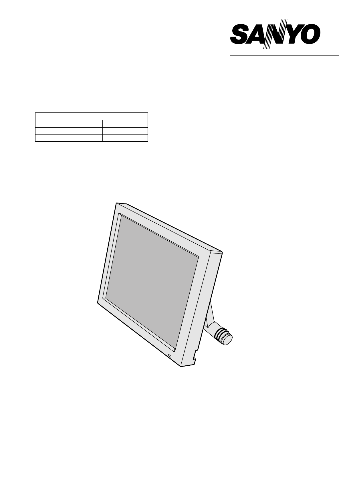
INDUSTRIAL MONITOR
PRODUCT CODE NO.
L
MU-T 12ATC/SS 1 938 102 12
LMU-TK12ATC(K)/SS
LMU-TK12ATC(K)/UK
1 938 102 37
1 938 102 38
LMU-TK12ATC
(GENERAL)
(With Touch Panel)
REFERENCE NO. SM 920016
Page 2

INDEX
Page
PRECAUTIONS ---------------------------------------------------------------------------------- 2
1, MAIN SPECIFICATION --------------------------------------------------------------------- 3
2, TROUBLE SHOOTING ---------------------------------------------------------------------- 4,5
3, MAINTENANCE
Disassembling the major components ------------------------------------------------------6
4, BLOCK DIAGRAM ---------------------------------------------------------------------------- 7
5, CONNECTION DIAGRAM ------------------------------------------------------------------ 8
6, TABLE OF SIGNAL NAME ----------------------------------------------------------------- 9,10
7, EXPLODED VIEW AND PARTS LIST
7-1Exploded View ---------------------------------------------------------------------------11
7-2 Parts List ------------------------------------------------------------------------------------- 12-14
8, APPENDIX ------------------------------------------------------------------------------------- 15
Refer to the separate volume user’s guide for instruction.
-1-
Page 3

PRECAUTIONS
Placement precautions
l Avoid placing the unit in humid or dusty places, or where it will be exposed to excessive heat
(direct sunlight, heaters, etc.)
l Do not step on or set anything on the AC cord.
DAMAGE TO THE AC CORD IS A SAFETY RISK AND CAN CAUSE A FIRE.
l Do not connect the unit to the same AC as outlet with appliances that generate large amounts of
interference (such as heaters with thermostats, appliances with motors, etc.). It is best to use a
completely separate electrical outlet.
l Keep the unit away from water. If water accidentally enters the unit, unplug the AC power cord
immediately. DO NOT PLUG IN THE UNIT AGAIN.
Handling precautions
l Avoid bending, kinking or damaging the AC power cord.
l Never insert or remove the power cord with wet hands. Also, be sure to hold cord by the plug when
removing it from the outlet.
l Do not remove any parts that are held in place with screws. (The unit does not contain any user
serviceable items.)
l Maintain standard room temperature (5oC to 40 oC, or 41oF to 104 oF) during use. Do not subject the
unit to shock or vibration. Do not move the unit while it is in use.
l A rapid increase in room temperature in cool weather can cause condensation to from inside the unit.
If this occurs, wait at least 15 minutes after turning the unit on before attempting to operate it.
-2-
Page 4
1.MAIN SPECIFICATION
Display
Liquid Crystal Panel: TFT
Display Size: 12.1''
Pixel Configuration: 800 x 600
Pixel Pitch: 0.308 x 0.308 mm
2
Brightness: 200 cd/m
Response Time: 50 ms
Contrast: 150 : 1 typ.
Angle of Visibility: Left 60 degrees,Right 60 degrees, Up 30 degrees, Down 45 degrees.
Video Control
Vertical signal 55 - 77Hz
Horizontal signal: 24 - 61 kHz
Colors: 16.19 million
Adjustment Functions: BRIGHTNESS, DOT-CLOCK, PHASE, H-POSITION, V-POSITION,
LEVEL, R-LEVEL, G-LEVEL, B-LEVEL
Plug & Play: VESA DDC1, DDC2B
Power Management: VESA DPMS
max.
Touch Panel
Type: Resistive (LMU-TK12AT) Capacitive (LMU-TK12ATC)
Electrical Resolution: 10bit (1024 x 1024)
Communication: Bi-directional asynchronous RS-232C serial communication
Physical
Input: Video 15pin mini D-SUB
Serial 9pin D-SUB
Power DC jack
Dimensions(Exclude Stand)
Weight: 2 kg (LMU-TK12AT) 2.2kg (LMU-TK12ATC)
Operating Conditions: Operating Temperature Operating: 5°C to 40°C
Power Supply:
/AC Adapter:
Power Consumption: 20 W (5W in Energy Saving mode)
Model
Input
Output
: 295 (W) x 233 (D) x 42 (H) mm
Storage: –20°C to 60°C
Humidity: 30% to 85% RH (no condensation)
LMU-TK12AT
GI40-US1225
100-240V 50-60Hz
12v 2.6A
LMU-TK12ATC
GI40-US1225
100-240VAC 1.0A-0.55A, 50-60Hz
DC 12v 2.5A
- 3 -
Page 5
2. TROUBLE SHOOTING
The "TROUBLESHOOTING for LCD Monitor" is described in below. Please refer to the manual "TROUBLE SHOOTING
for Touch-Screen" in CD-ROM.
No. SYMPTOM CHECK POINTS TREATMENTS
1 No Picture with Power
Indicator OFF
2 No Picture with Power
Indicator in Amber
3 No Picture with Power
Indicator in Green
1 Is the Power to a LCD monitor "ON"? Check AC outlet, AC cord, DC Jack and
Power switch for a LCD monitor
2 Is an AC Adapter defective? Replace an AC Adapter with the new
one
3 Is the wire harness between main PCB
and DC-IN PCB secured firmly ?
4 The Power Supply circuit on main PCB
may be defective
1 Is the Power to a computer "ON"? Check AC outlet, AC cord, DC Jack and
2 Is a computer standing by ? Be out of standing by condition, by
3 The Image Processing circuit on main
PCB may be defective
1 Is a screen saver programming
running ?
2 Is a signal cable connected securely ? Check the connection of a signal cable
3 Disconnected a signal cable ? or Bent a
terminal pin ?
Check the connection
Replace the main PCB with the new one
Power switch for a computer
operating to a computer
Replace the main PCB with the new one
Press any key or touch the mouse, to
end the screen saver program
Replace a signal cable with the new one
4 No Picture with Power
Indicator blinking in
Green
4 Is the computer's signal timing not
agreeable to the LCD's specification ?
5 Is the wire harness between Inverter
PCB and a LCD module secured
firmly ?
6 Is the wire harness between main PCB
and Inverter PCB secured firmly ?
7 The Brightness control volume may be
defective
8 The LCD module may be defective Replace a LCD module with the new
9 The Inverter unit may be defective Replace an Inverter unit with the new
10 The display circuit on main PCB may
be defective ?
1 Is a computer standing by ? Be out of standing by condition, by
2 Is a signal cable connected securely ? Check the connection of a signal cable
3 Disconnected a signal cable ? or Bent a
terminal pin ?
Adjust the computer's signal timing, if
possible
Check the connection of wire harness
Check the connection of wire harness
Replace the Volume PCB with new one,
and check the screen
one
one
Replace the main PCB with the new one
operating to a computer
Replace a signal cable with the new one
It is possible to treated by end-user
It must be treated by Professional Technical Staff
It might be possible to treat by end-user in some case.
- 4 -
Page 6

No. SYMPTOM CHECK POINTS TREATMENTS
5 White/Grey on whole
screen
(Nothing on screen)
6 Screen's display range
is incorrect
7 Screen is distorted
8 Part of colors(R/G/B) is
not displayed
Black line is appeared
vertically
1 Is the wire harness between main PCB
and LCD module secured firmly ?
2 Is the LCD module defective ? Replace a LCD module with the new
3 Is the main PCB defective ? Replace the main PCB with the new one
1 Is the adjustment for screen performed
correctly ?
2 Is the output level on image from a
computer not agreeable to LCD's
specification ?
3 Is the size of screen set correctly ? Set the size of screen again(refer to
1 Is the adjustment for screen performed
correctly ?
2 Is a signal cable connected securely ? Check the connection of a signal cable
3 Is a sig nal cable extended ? Don't extend a signal cable
4 Is the output level on image from a
computer not agreeable to LCD's
specification ?
5 The Image Processing circuit on main
PCB may be defective
1 Is a signal cable connected securely ? Check the connection of a signal cable
2 Is the connection between main PCB
and a LCD module securely ?
3 The Image Processing circuit on main
PCB may be defective
Check the connection of wire harness
one
Adjust the screen correctly
Check the specification of a computer
User's Manual for computer)
Adjust the screen correctly
Check the specification of a computer
Replace the main PCB with the new one
Check the connector
Replace the main PCB with the new one
It is possible to treated by end-user
It must be treated by Professional Technical Staff
It might be possible to treat by end-user in some case
- 5 -
Page 7

3 MAINTENANCE
Disassembling the major components
(1) Cabinet
1. Unscrew to secure the cabinet (8-position)
2. Pull the cabinet upward to remove it
(2) LCD Panel and Touch Panel
1. The Touch panel is on the LCD panel. The clearance between the Touch Panel and
the bottom case are filled with 8 rubber pieces. Pull the right side of the Touch panel
upward carefully, then turn it over at the left side of the bot t om case.
2. Unscrew to secure the LCD panel (4-position)
3. Pull the LCD panel up carefully. Disconnect the FPC from main PCB, and pull the
connector out to inverter unit.
4. Unscrew to secure the earth terminal (1-position)
5. Disconnect the cable on the main PCB (Orange, Grey)
6. Disconnect the cable on the Touch controller PCB
(3) Inverter Unit
1. Unscrew to secure the Inverter Unit (3-position)
2. Disconnect the cable from the main PCB
(4) Main PCB
1. Pull the RGB signal cable out
2. Unscrew to secure the main PCB (4-position)
3. Disconnect the cables on the main PCB (6-position)
/ Two cables have already been disconnected
/ One connector from the Joint PCB
/ One connector from the VR PCB
/ One connector from the DC-IN PCB
/ One connector from the Inverter PCB
4. Unscrew to secure the bracket for RGB Connector (2-position)
(5) Touch Controller PCB
1. Unscrew to secure the Touch controller PCB (2-position)
2. Disconnect the serial cable
(6) Serial Cable (Connector and Cable with bracket)
1. Unscrew to secure the bracket for serial cable (2-position)
(7) Joint PCB
1. Unscrew to secure the Joint PCB (2-position)
2. Disconnect the cables from the main PCB and the LED PCB
(8) VR PCB
1. Unscrew to secure the VR PCB (2-position)
2. Disconnect the cable to the main PCB
(9) DC-IN PCB
1. Unscrew to secure the DC-IN PCB (2-position)
2. Disconnect one cable from Power Switch, and another cable from the main PCB
(10) Power Switch
1. Remove the Power Switch, while pressing the hook of the Power Swit ch
(11) LED PCB
1. Unscrew to secure the LED PCB (1-position)
2. One cable has already been disconnected.
Page 8

4 BLOCK DIAGRAM
EEROM
Micro
Video
Video
SVGA
ADC
OSD Key
V
PLL
H
Amp
Controller
Controller
Cheetah 2
LED
ROM
TFT
LCD
Panel
R
G
B
RS232C
Clock Gen.
Volume
Control Board Touch Screen
Inverter
- 7 -
Page 9

5. CONNECTION DIAGRAM
Inverter
CN2
123
N.C.
H.V
LGND
TFT 12-inch
Liquid Crystal
Display
AC
AC
Adapter
Plug
Unit
CN1
12345
VR1
ON (5V)
+12V
VR2
GND
12345
P1
41
40
39
38
37
36
35
34
33
32
31
30
29
28
27
26
25
24
23
22
21
20
19
18
17
16
15
14
13
12
11
10
9
8
7
6
5
4
3
2
1
N.C.
VDD
VDD
TEST
DE
VSS
B5
B4
B3
VSS
B2
B1
B0
VSS
VSS
VSS
G5
G4
G3
VSS
G2
G1
G0
VSS
VSS
VSS
R5
R4
R3
VSS
R2
R1
R0
VSS
VSS
VSS
VSYNC
HSYNC
VSS
DCLK
VSS
41
40
39
38
37
36
35
34
33
32
31
30
29
28
27
26
25
24
23
22
21
20
19
P4
18
17
16
15
14
13
12
11
10
9
8
7
6
5
4
3
2
1
J201
1
GND
+12V
DC IN
P.C.B
1
P7
Analogue
Interface
P.C.B
SANDDUNE 1
P6
2
1
CN201
2
CN202
2
LED
123
P.C.B
Power Switch
CN401
RED
GND
GREEN
123
CN501
Connector
CN6
CN503
CN502
P.C.B
Volume
P.C.B
5
GND
4
UP
3
DOWN
2
SEL
1
MENU
External OSD
Switch
8
7
6
5
4
3
P2
2
1
3
2
1
P5
1
9
2
10
3
11
4
12
5
13
6
14
7
15
8
VR2
VRC
VR1
RED
N.C.
GREEN
GND
BLUE
N.C.
N.C.
SDA
GND
HSYNC
GND
VSYNC
GND
SCL
GND
LED-G
VCC
LED-R
GND
UP
DOWN
SEL
MENU
8
7
6
5
4
3
2
1
3
2
1
Touch Screen
1
N.C.
2
N.C.
3
N.C.
4
N.C.
5
POWER GND
6
CHASSIS GND
7
+12V
8
BACK
9
UR
LR
UL
LL
1
2
P8
1
RED
9
N.C.
2
GREEN
10
GND
3
BLUE
11
N.C.
4
N.C.
12
SDA
5
GND
13
HSYNC
6
GND
14
VSYNC
7
GND
15
SCL
8
GND
594837261
7
N.C.
JP1
6
N.C.
5
GND
4
CTS
3
TXD
2
RXD
1
RTS
N.C.
N.C.
N.C.
N.C.
5
9
4
8
3
7
2
6
1
5
N.C.
9
N.C.
4
8
3
7
2
N.C.
6
N.C.
1
Controller
10
11
12
JP2
Touch Screen
GND
DTR
NC
CTS
Personal
Computer
DSR
DCD
RTS
TXD
RXD
- 8 -
Page 10

6. TABLE OF SIGNAL NAME
Symbol Signal Name Location Notes
DCLK Data Clock P4-2
HSYNC Horizontal Sync. P4-4 This signal is invalid, input H or L.
VSYNC Vertical Sync. P4-5 This signal is invalid, input H or L.
R0 Red Data (LSB) P4-9
R1 Red Data P4-10
R2 Red Data P4-11
R3 Red Data P4-13
R4 Red Data P4-14
R5 Red Data (MSB) P4-15
G0 Green Data (LSB) P4-19
G1 Green Data P4-20
G2 Green Data P4-21
G3 Green Data P4-23
G4 Green Data P4-24
G5 Green Data (MSB) P4-25
B0 Blue Data (LSB) P4-29
B1 Blue Data P4-30
B2 Blue Data P4-31
B3 Blue Data P4-33
B4 Blue Data P4-34
B5 Blue Data (MSB) P4-35
DE Data Enable (positive) P4-37
TEST Display test P4-38 For display test, to be L.
VDD Power Supply P4-39 3.3V
VDD Power Supply P4-40 3.3V
VIN Inverter Power P1-1 12V
VR1,2 Controlled Voltage P13,4
ON Back Light Control P1-5 H : Light ON
VR1,2 Brightness Volume P5-1,3
VRC Brightness Volume P5-2
MENU MENU Key P2-1
SEL SELECT Key P2-2
DOWN DOWN Key P2-3
UP UP Key P2-4
LED-R LED Red P2-6
LED-G LED Green P2-8
RED VIDEO Red Signal P6-1
GREEN VIDEO Green Signal P6-2
BLUE VIDEO Blue Signal P6-3
HSYNC Horizontal Sync. P6-13
VSYNC Vertical Sync. P6-14
SDA DDC Data P6-12
SCL DDC Clock P6-15
VR1,2 Controlled Voltage P1-3,4
ON Back Light Control P1-5 H : Light ON
- 9 -
Page 11

6. TABLE OF SIGNAL NAME
Touch Screen Controller
Symbol Signal Name Location Notes
RTS Request To Send JP1-1
RXD Receive Data JP1-2
TXD Transmit Data JP1-3
CTS Clear To Send JP1-4
DCD Data Carrier Detect NC
DTR Data Terminal Ready NC
GND Signal ground NC
DSR Data Set Ready NC
GND Chassis (earth) ground NC
UR Upper right (UR) corner JP2-9
LR Lower right (LR) corner JP2-10
UL Upper left (UL) corner JP2-11
LL Lower left (LL) corner JP2-12
- 10 -
Page 12

7. EXPLODED VIEW AND PART RLIST
(LMU-TK12ATC/SS)
(LMU-TK12ATC(K)/SS)
(LMU-TK12ATC(K)/UK)
41
42
46
1
36
6
44
43
47
40
37
PCB
5
21
34
8
31
24
LCD
1
PCB
1
4
29
45
7
27
3
5
5
25
39
PCB
2
30
2
35
33
4
26
- 11 -
PCB
3
S1
28
PCB
4
Page 13

7-2. PARTS LIST
[LMU-TK12ATC/SS]
PRODUCT SAFETY NOTICE
Each precaution in this manual should be followed during servicing. Components identified with the IEC symbol in the parts list and the schematic
diagram designate components in whitch safety can be of special significance. When replacing a component identified with use only the replacement
parts designated, or parts with the same ratings of resistance, wattage or voltage that are designated in the parts list in this manual.
Leakage-current or resistance measurements must be made to determine that exposed parts are acceptably insulated from the supply circuit before
returning the product to the customer.
Ref. No. PART No. DESCRIPTION Q'ty Ref. No. PART No. DESCRIPTION Q'ty
OUTER
632 872 2563 OUTER CARTON,TC(K) 1
632 758 4209 LABEL, BAR CODE 1
INDIVIDUAL
632 872 2570 PAD, BOTTOM 1
632 872 2587 PAD, SIDE 1
632 872 2594 PAD, ACCESSORY 1
632 872 2600 PAD, TOP 1
632 298 2376 POLYETHYLENE BAG 1
SERIAL CABLE CNT
632 822 4425 POLYETHYLENE BAG, 300X450 1
632 607 4824 POLYETHYLENE BAG,L180X270 1
MANUAL
632 567 2588 POLYETHYLENE BAG, 200X300 1
RGB CABLE
632 607 4824 POLYETHYLENE BAG,L180X270 1
SERIAL CABLE
CLAMP-MAIN-CHASSIS
411 001 8702 SCR BIN 3X6 1
CHASSIS - LED PCB
411 001 8702 SCR BIN 3X6 4
LCD - CHASSIS
632 888 1598 LABEL, TIK 1
4 632 872 9777 PLATE SPRING, EARTH 4
LCD - BOTTOM
5 632 250 0655 WIRE FIXTURE 2
411 030 5000 SCR BIN 2X3 1
WIRE FIX.-CHASSIS
6 632 887 8260 CUSHION, FELT, FELT 1
TOUCH PANEL CN
7 661 020 3398 STAND ASSY 1
411 041 8700 SCR PAN 3X6 2
632 607 4732 POLYETHYLENE BAG,L 70X100 1
632 607 4855 POLYETHYLENE BAG,L 260X380 1
ACCESSORY
41 632 860 9925 FLOPPY DISK 1
42 632 867 2325 CD-ROM DISK, TOUCHWARE 1
632 869 1968 INSTRUCTION MANUAL,ENGLIS 1
632 892 8422 LEAFLET, ADAPTOR 1
632 869 1975 INSTRUCTION MANUAL,GERMAN 1
661 000 1031 LEAFLET, CE 1
43 632 880 5488 AC ADAPTOR 1
44 632 873 4696 VGA CABLE, 150CM 1
45 632 866 8397 SERIAL CABLE, 1.8M 1
46 632 876 9834 REMOTE CONTROLLER ASS'Y 1
632 875 1815 CONTROLL BOX 1
632 876 9841 LABEL, 1
632 887 7072 CORE, 50 1
OR 661 001 7278 CORE 1
OR 632 876 0480 CORE, 50 1
!
47 632 873 0926 AC CORD, 1
47 OR 632 880 1596 AC CORD, 1.8M 1
!
CABINET
1 632 880 1336 TOP LID ASSY 1
CHASSIS
2 661 037 0427 BOTTOM LID ASSY 1
3 632 868 5615 BASE, CUSHION 2
411 001 8702 SCR BIN 3X6 2
CHASSIS - DC-IN
411 030 8803 SCR BIN 2.5X6,CHASSIS-VR 2
411 030 6403 SCR BIN 2X5 3
CHASSIS - INV.
411 030 6403 SCR BIN 2X5 2
CHASSIS - JOINT
411 001 8702 SCR BIN 3X6 2
CHASSIS - CONTROL
411 001 8702 SCR BIN 3X6 3
CHASSIS - MAIN
411 008 0402 WASHER OUT TW 3 1
8 632 886 5789 CLAMP 1
411 001 8900 SCR BIN 3X8 1
21 632 880 1442 FPC BOARD ASS'Y 1
24 632 868 6261 WIRE HARNESS, MAIN-INV. 1
25 632 873 7796 WIRE HARNESS, MAIN-VOLUME 1
26 632 868 6247 WIRE HARNESS, MAIN-DC IN 1
27 632 837 2713 CORE 1
HARNESS MAIN-DC IN
28 632 873 7802 WIRE HARNESS, DC IN-PWR 1
29 632 869 6796 WIRE HARNESS, MAIN-JOINT 1
40 661 002 9882 CORE 1
30 661 037 0113 DC-AC INVERTER ASSY 1
31 632 861 4868 CABLE, RS232C 1
33 661 001 2570 SPECIAL SCREW,CABLE 2
34 632 889 5083 BRACKET, SERIAL,CABLE 1
35 632 773 6011 SPECIAL SCREW,P6(VGA) 2
LCD1 632 884 7655 LIQUID CRYSTAL DISPLAY, 1
36 661 021 0624 TOUCH SENSOR ASSY 1
37 632 886 2443 SERIAL CONTROLLER 1
S1 632 887 8024 SEESAW SWITCH 1
39 632 873 4139 GASKET 2
MAIN P.C.B. ASSEMBLY
PCB1 661 019 8946 PW BOARD ASSY, MAIN 1
VR P.C.B. ASSEMBLY
PCB2 632 843 3469 PW BOARD ASS'Y, VR 1
DC IN P.C.B. ASSEMBLY
PCB3 632 873 4146 PW BOARD ASS'Y, DC IN 1
LED P.C.B. ASSEMBLY
PCB4 632 869 5256 PW BOARD ASS'Y, LED 1
JOINT P.C.B. ASSEMBLY
PCB5 632 869 5263 PW BOARD ASS'Y, JOINT 1
!
!
CHARGER
CHASSIS ELC.
NOTES: 1. Part orders must contain Model Number, Part Number and Description.
2. Ordering quantity of screws and resistors must be multiple of 10 pcs.
3. Regular type resistor and capacitor are omitted. Check the schematic diagram for these values.
- 12 -
Page 14

[LMU-TK12ATC(K)/SS]
PRODUCT SAFETY NOTICE
Each precaution in this manual should be followed during servicing. Components identified with the IEC symbol in the parts list and the schematic
diagram designate components in whitch safety can be of special significance. When replacing a component identified with use only the replacement
parts designated, or parts with the same ratings of resistance, wattage or voltage that are designated in the parts list in this manual.
Leakage-current or resistance measurements must be made to determine that exposed parts are acceptably insulated from the supply circuit before
returning the product to the customer.
Ref. No. PART No. DESCRIPTION Q'ty Ref. No. PART No. DESCRIPTION Q'ty
OUTER
632 872 2563 OUTER CARTON,TC(K) 1
632 758 4209 LABEL, BAR CODE 1
INDIVIDUAL
632 872 2570 PAD, BOTTOM 1
632 872 2587 PAD, SIDE 1
632 872 2594 PAD, ACCESSORY 1
632 872 2600 PAD, TOP 1
632 298 2376 POLYETHYLENE BAG 1
SERIAL CABLE CNT
632 822 4425 POLYETHYLENE BAG, 300X450 1
632 607 4824 POLYETHYLENE BAG,L180X270 1
MANUAL
632 567 2588 POLYETHYLENE BAG, 200X300 1
RGB CABLE
632 607 4824 POLYETHYLENE BAG,L180X270 1
SERIAL CABLE
8 632 886 5789 CLAMP 1
411 001 8900 SCR BIN 3X8 1
CLAMP-MAIN-CHASSIS
411 001 8702 SCR BIN 3X6 1
CHASSIS - LED PCB
411 001 8702 SCR BIN 3X6 4
LCD - CHASSIS
4 632 872 9777 PLATE SPRING, EARTH 4
LCD - BOTTOM
5 632 250 0655 WIRE FIXTURE 2
411 030 5000 SCR BIN 2X3 1
WIRE FIX.-CHASSIS
6 632 887 8260 CUSHION, FELT, FELT 1
TOUCH PANEL CN
7 661 020 3398 STAND ASSY 1
411 041 8700 SCR PAN 3X6 2
632 607 4732 POLYETHYLENE BAG,L 70X100 1
632 607 4855 POLYETHYLENE BAG,L 260X380 1
!
!
CHARGER
ACCESSORY
41 632 860 9925 FLOPPY DISK 1
42 632 867 2325 CD-ROM DISK, TOUCHWARE 1
632 869 1968 INSTRUCTION MANUAL,ENGLIS 1
632 892 8422 LEAFLET, ADAPTOR 1
632 869 1975 INSTRUCTION MANUAL,GERMAN 1
661 000 1031 LEAFLET, CE 1
43 632 880 5488 AC ADAPTOR 1
44 632 873 4696 VGA CABLE, 150CM 1
45 632 866 8397 SERIAL CABLE, 1.8M 1
46 632 876 9834 REMOTE CONTROLLER ASS'Y 1
632 875 1815 CONTROLL BOX 1
632 876 9841 LABEL, 1
632 887 7072 CORE, 50 1
OR 661 001 7278 CORE 1
OR 632 876 0480 CORE, 50 1
!
47 632 873 0926 AC CORD, 1
47 OR 632 880 1596 AC CORD, 1.8M 1
!
CABINET
1 661 021 1898 TOP LID ASSY 1
411 174 2705 SCR BIN 2.5X5 8
TOP LID - BOTTOM
21 632 880 1442 FPC BOARD ASS'Y 1
24 632 868 6261 WIRE HARNESS, MAIN-INV. 1
25 632 873 7796 WIRE HARNESS, MAIN-VOLUME 1
26 632 868 6247 WIRE HARNESS, MAIN-DC IN 1
27 632 837 2713 CORE 1
HARNESS MAIN-DC IN
28 632 873 7802 WIRE HARNESS, DC IN-PWR 1
29 632 869 6796 WIRE HARNESS, MAIN-JOINT 1
40 661 002 9882 CORE 1
30 632 880 1428 DC-AC INVERTER ASS'Y 1
31 632 861 4868 CABLE, RS232C 1
33 661 001 2570 SPECIAL SCREW,CABLE 2
34 632 889 5083 BRACKET, SERIAL,CABLE 1
35 632 773 6011 SPECIAL SCREW,P6(VGA) 2
LCD1 632 884 7655 LIQUID CRYSTAL DISPLAY, 1
36 661 021 0624 TOUCH SENSOR ASSY 1
37 632 886 2443 SERIAL CONTROLLER 1
S1 632 887 8024 SEESAW SWITCH 1
39 632 873 4139 GASKET 2
PCB1 661 019 8946 PW BOARD ASSY, MAIN 1
CHASSIS ELC.
MAIN P.C.B. ASSEMBLY
CHASSIS
2 661 021 2468 BOTTOM LID ASSY 1
3 632 868 5615 BASE, CUSHION 2
411 001 8702 SCR BIN 3X6 2
CHASSIS - DC-IN
411 030 8803 SCR BIN 2.5X6,CHASSIS-VR 2
411 030 6403 SCR BIN 2X5 3
CHASSIS - INV.
411 030 6403 SCR BIN 2X5 2
CHASSIS - JOINT
411 001 8702 SCR BIN 3X6 2
CHASSIS - CONTROL
411 001 8702 SCR BIN 3X6 3
CHASSIS - MAIN
411 008 0402 WASHER OUT TW 3 1
PCB2 632 843 3469 PW BOARD ASS'Y, VR 1
PCB3 632 873 4146 PW BOARD ASS'Y, DC IN 1
PCB4 632 869 5256 PW BOARD ASS'Y, LED 1
PCB5 632 869 5263 PW BOARD ASS'Y, JOINT 1
VR P.C.B. ASSEMBLY
DC IN P.C.B. ASSEMBLY
LED P.C.B. ASSEMBLY
JOINT P.C.B. ASSEMBLY
NOTES: 1. Part orders must contain Model Number, Part Number and Description.
2. Ordering quantity of screws and resistors must be multiple of 10 pcs.
3. Regular type resistor and capacitor are omitted. Check the schematic diagram for these values.
- 13 -
Page 15

[LMU-TK12ATC(K)/UK]
PRODUCT SAFETY NOTICE
Each precaution in this manual should be followed during servicing. Components identified with the IEC symbol in the parts list and the schematic
diagram designate components in whitch safety can be of special significance. When replacing a component identified with use only the replacement
parts designated, or parts with the same ratings of resistance, wattage or voltage that are designated in the parts list in this manual.
Leakage-current or resistance measurements must be made to determine that exposed parts are acceptably insulated from the supply circuit before
returning the product to the customer.
!
!
NOTES: 1. Part orders must contain Model Number, Part Number and Description.
2. Ordering quantity of screws and resistors must be multiple of 10 pcs.
3. Regular type resistor and capacitor are omitted. Check the schematic diagram for these values.
!
!
OUTER
632 872 2563 OUTER CARTON,TC(K) 1
632 758 4209 LABEL, BAR CODE 1
INDIVIDUAL
632 872 2570 PAD, BOTTOM 1
632 872 2587 PAD, SIDE 1
632 872 2594 PAD, ACCESSORY 1
632 872 2600 PAD, TOP 1
632 298 2376 POLYETHYLENE BAG 1
SERIAL CABLE CNT
632 822 4425 POLYETHYLENE BAG, 300X450 1
632 607 4824 POLYETHYLENE BAG,L180X270 1
MANUAL
632 567 2588 POLYETHYLENE BAG, 200X300 1
RGB CABLE
632 607 4824 POLYETHYLENE BAG,L180X270 1
SERIAL CABLE
ACCESSORY
41 632 860 9925 FLOPPY DISK 1
42 632 867 2325 CD-ROM DISK, TOUCHWARE 1
632 869 1968 INSTRUCTION MANUAL,ENGLIS 1
632 892 8422 LEAFLET, ADAPTOR 1
661 000 1031 LEAFLET, CE 1
43 632 880 5488 AC ADAPTOR 1
44 632 873 4696 VGA CABLE, 150CM 1
45 632 866 8397 SERIAL CABLE, 1.8M 1
46 632 876 9834 REMOTE CONTROLLER ASS'Y 1
632 875 1815 CONTROLL BOX 1
632 876 9841 LABEL, 1
632 887 7072 CORE, 50 1
OR 661 001 7278 CORE 1
OR 632 876 0480 CORE, 50 1
47 632 892 0792 AC CORD, 1.8M 1
47 OR 632 893 2610 AC CORD, 1.8M 1
CABINET
1 632 880 1336 TOP LID ASSY 1
CHASSIS
2 661 021 2468 BOTTOM LID ASSY 1
3 632 868 5615 BASE, CUSHION 2
411 001 8702 SCR BIN 3X6 2
CHASSIS - DC-IN
411 030 8803 SCR BIN 2.5X6,CHASSIS-VR 2
411 030 6403 SCR BIN 2X5 3
CHASSIS - INV.
411 030 6403 SCR BIN 2X5 2
CHASSIS - JOINT
411 001 8702 SCR BIN 3X6 2
CHASSIS - CONTROL
411 001 8702 SCR BIN 3X6 3
CHASSIS - MAIN
411 008 0402 WASHER OUT TW 3 1
8 632 886 5789 CLAMP 1
411 001 8900 SCR BIN 3X8 1
CLAMP-MAIN-CHASSIS
411 001 8702 SCR BIN 3X6 1
CHASSIS - LED PCB
411 001 8702 SCR BIN 3X6 4
LCD - CHASSIS
632 888 1598 LABEL, TIK 1
4 632 872 9777 PLATE SPRING, EARTH 4
4 LCD - BOTTOM
5 632 250 0655 WIRE FIXTURE 2
411 030 5000 SCR BIN 2X3 1
WIRE FIX.-CHASSIS
6 632 887 8260 CUSHION, FELT, FELT 1
6 TOUCH PANEL CN
CHARGER
7 661 020 3398 STAND ASSY 1
411 041 8700 SCR PAN 3X6 2
632 607 4732 POLYETHYLENE BAG,L 70X100 1
632 607 4855 POLYETHYLENE BAG,L 260X380 1
CHASSIS ELC.
21 632 880 1442 FPC BOARD ASS'Y 1
24 632 868 6261 WIRE HARNESS, MAIN-INV. 1
25 632 873 7796 WIRE HARNESS, MAIN-VOLUME 1
26 632 868 6247 WIRE HARNESS, MAIN-DC IN 1
27 632 837 2713 CORE 1
HARNESS MAIN-DC IN
28 632 873 7802 WIRE HARNESS, DC IN-PWR 1
29 632 869 6796 WIRE HARNESS, MAIN-JOINT 1
40 661 002 9882 CORE 1
30 661 037 0113 DC-AC INVERTER ASSY 1
31 632 861 4868 CABLE, RS232C 1
33 661 001 2570 SPECIAL SCREW,CABLE 2
34 632 889 5083 BRACKET, SERIAL,CABLE 1
35 632 773 6011 SPECIAL SCREW,P6(VGA) 2
LCD1 632 884 7655 LIQUID CRYSTAL DISPLAY, 1
36 661 021 0624 TOUCH SENSOR ASSY 1
37 632 886 2443 SERIAL CONTROLLER 1
S1 632 887 8024 SEESAW SWITCH 1
39 632 873 4139 GASKET 2
MAIN P.C.B. ASSSEMBLY
PCB1 661 019 8946 PW BOARD ASSY, MAIN 1
VR P.C.B. ASSEMBLY
PCB2 632 843 3469 PW BOARD ASS'Y, VR 1
DC IN P.C.B. ASSEMBLY
PCB3 632 873 4146 PW BOARD ASS'Y, DC IN 1
LED P.C.B. ASSEMBLY
PCB4 632 869 5256 PW BOARD ASS'Y, LED 1
JOINT P.C.B. ASSEMBLY
PCB5 632 869 5263 PW BOARD ASS'Y, JOINT 1
- 14 -
Ref. No. PART No. DESCRIPTION Q'ty Ref. No. PART No. DESCRIPTION Q'ty
Page 16

APPENDIX
Version of Firmware
The Version of Firmware is displayed on screen.
Turn the Power Switch to ‘OFF’. While pressing of the [SELECT] button, turn the Power
Switch to ‘ON’.
- 15 -
 Loading...