

Sanyo lmu tk12a schematic
SERVICE MANUAL
INDUSTRIAL MONITOR
PRODUCT CODE NO .
LMU-TK12A 1 938 102 06
LMU-TK12AT 1 938 102 07
LMU-TK12A (Without Touch Panel)
LMU-TK12AT (With Touch Panel)
(GENERAL)
REFERENCE NO. SM 920004

INDEX
Page
PRECAUTIONS ----------------------------------------------------------------------------------2
1, MAIN SPECIFICATION ---------------------------------------------------------------------3
2, TROUBLE SHOOTING ---------------------------------------------------------------------- 4,5
3, MAINTENANCE
Disassembling the major components ------------------------------------------------------6
4, BLOCK DIAGRAM ---------------------------------------------------------------------------- 7
5, CONNECTION DIAGRAM ------------------------------------------------------------------ 8
6, TABLE OF SIGNAL NAME ----------------------------------------------------------------- 9,10
7, EXPLODED VIEW AND PARTS LIST
7-1Exploded View ---------------------------------------------------------------------------11,12
7-2 Parts List ------------------------------------------------------------------------------------- 13,14
8, APPENDIX ------------------------------------------------------------------------------------- 15
Refer to the separate volume user’s guide for instruction.
-1-

PRECAUTIONS
Placement precautions
l Avoid placing the unit in humid or dusty places, or where it will be exposed to excessive heat
(direct sunlight, heaters, etc.)
l Do not step on or set anything on the AC cord.
DAMAGE TO THE AC CORD IS A SAFETY RISK AND CAN CAUSE A FIRE.
l Do not connect the unit to the same AC as outlet with appliances that generate large amounts of
interference (such as heaters with thermostats, appliances with motors, etc.). It is best to use a
completely separate electrical outlet.
l Keep the unit away from water. If water accidentally enters the unit, unplug the AC power cord
immediately. DO NOT PLUG IN THE UNIT AGAIN.
Handling precautions
l Avoid bending, kinking or damaging the AC power cord.
l Never insert or remove the power cord with wet hands. Also, be sure to hold cord by the plug when
removing it from the outlet.
l Do not remove any parts that are held in place with screws. (The unit does not contain any user
serviceable items.)
l Maintain standard room temperature (5oC to 40 oC, or 41oF to 104 oF) during use. Do not subject the
unit to shock or vibration. Do not move the unit while it is in use.
l A rapid increase in room temperature in cool weather can cause condensation to from inside the unit.
If this occurs, wait at least 15 minutes after turning the unit on before attempting to operate it.
-2-
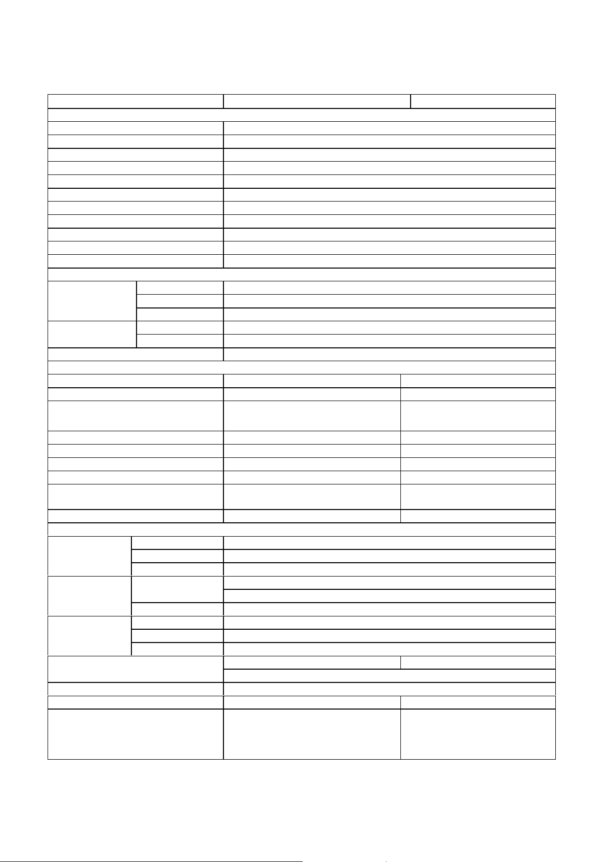
1. MAIN SPECIFICATION
Model Name LMU-TK12AT LMU-TK12A
Display
Panel Type TFT
Screen Size 12.1"
Pixel Pitch 0.308 X 0.308 mm
Effective Viewing Area 246.0 X 184.5 mm
Pixel Format 800 X 600
Brightness 200cd/m2 typ.
Response Time 50ms
Contrast 150 : 1 typ.
Viewing Angle (minimum) Left & Right :60 deg Up :30 deg Down :45 deg
Back Light CCFL x 1
Panel Life Time 20,000 hours
Video Control
System Analog RGB
Input Signal
Frequencies
Colors 16.19million
Touch panel
Type Resistive Electrical Resolution 10bit (1,024 X 1,024) -
Communication
Baud rate 9,600 BPS (1,200 - 19,200 BPS) -
Data 7 bit (7bit or 8bit) Stop bit 2 bit (1bit or 2bit) Parity non (odd, even, or non) -
Touch Life
Touch Down Speed 15 ms -
Physical
Power Supply
(AC Adapter)
Power Supply Consumption
Dimensions 295(W) X 233(D) X 42(H) mm
Weight 2.0 kg 1.8 kg
Accessories
Video 0.7Vp-p 75 ohm
Sync.Type/Level Separate TTL (+/-)
Horizontal 24.8k - 53.7kHzSynchronization
Vertical 56.4 - 85Hz
Bi-directional asynchronous RS-
232C serial communication
Greater than 20 million touches
in any location.
Video Signal 15pin mini D-Sub
Serial 9pin D-SubInput
Power Supply DC Jack
Operating
Temperature
Humidity 30% to 80% RH
Model Name G140-US1225
Input 100-240V 1.0A-0.55A, 50-60Hz
Output 12V 2.5A
20W max. 15W max.
AC Adapter, Power Cord, RGB
cable, Serial cable, OSD control box,
Adjustment FD, Touch Ware
CD-ROM, User's Guide
operating : 5oC to 40 oC
Storage : -20 oC to 60 oCEnvironment
5W in Energy Saving mode
AC Adapter, Power Cord, RGB
cable, OSD control box,
Adjustment FD, User's Guide
-
-
- 3 -
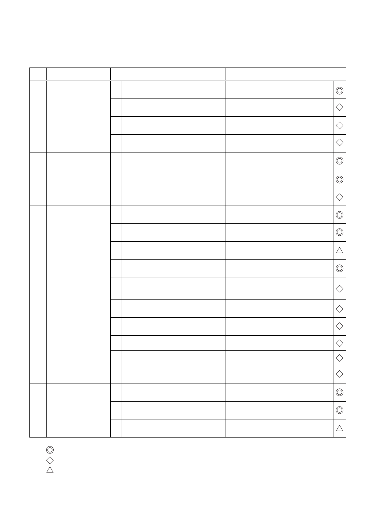
2. TROUBLE SHOOTING
The "TROUBLESHOOTING for LCD Monitor" is described in below. Please refer to the manual "TROUBLE SHOOTING
for Touch-Screen" in CD-ROM.
No. SYMPTOM CHECK POINTS TREATMENTS
1 No Picture with Power
Indicator OFF
2 No Picture with Power
Indicator in Amber
3 No Picture with Power
Indicator in Green
1 Is the Power to a LCD monitor "ON"? Check AC outlet, AC cord, DC Jack and
Power switch for a LCD monitor
2 Is an AC Adapter defective? Replace an AC Adapter with the new
one
3 Is the wire harness between main PCB
and DC-IN PCB secured firmly ?
4 The Power Supply circuit on main PCB
may be defective
1 Is the Power to a computer "ON"? Check AC outlet, AC cord, DC Jack and
2 Is a computer standing by ? Be out of standing by condition, by
3 The Image Processing circuit on main
PCB may be defective
1 Is a screen saver programming
running ?
2 Is a signal cable connected securely ? Check the connection of a signal cable
3 Disconnected a signal cable ? or Bent a
terminal pin ?
Check the connection
Replace the main PCB with the new one
Power switch for a computer
operating to a computer
Replace the main PCB with the new one
Press any key or touch the mouse, to
end the screen saver program
Replace a signal cable with the new one
4 No Picture with Power
Indicator blinking in
Green
4 Is the computer's signal timing not
agreeable to the LCD's specification ?
5 Is the wire harness between Inverter
PCB and a LCD module secured
firmly ?
6 Is the wire harness between main PCB
and Inverter PCB secured firmly ?
7 The Brightness control volume may be
defective
8 The LCD module may be defective Replace a LCD module with the new
9 The Inverter unit may be defective Replace an Inverter unit with the new
10 The display circuit on main PCB may
be defective ?
1 Is a computer standing by ? Be out of standing by condition, by
2 Is a signal cable connected securely ? Check the connection of a signal cable
3 Disconnected a signal cable ? or Bent a
terminal pin ?
Adjust the computer's signal timing, if
possible
Check the connection of wire harness
Check the connection of wire harness
Replace the Volume PCB with new one,
and check the screen
one
one
Replace the main PCB with the new one
operating to a computer
Replace a signal cable with the new one
It is possible to treated by end-user
It must be treated by Professional Technical Staff
It might be possible to treat by end-user in some case.
- 4 -
 Loading...