

Page 1
SERVICE MANUAL
15" COLOR LCD MONITOR
PRODUCT CODE NO .
LMU-TF150A2
1 938 102 10
LMU-TF150A2
(GENERAL)
SANYO Electric Co., Ltd.
OSAKA, JAPAN
REFERENCE NO. SM 920008
Page 2

INDEX
Page
PRECAUTIONS ----------------------------------------------------------------------------------- 2
1, MAIN SPECIFICATION ----------------------------------------------------------------------3
2, TROUBLE SHOOTING ---------------------------------------------------------------------- 4,5,6
3, MAINTENANCE
Disassembling the major components ---------------------------------------------- 7
4, BLOCK DIAGRAM ---------------------------------------------------------------------------- 8
5, CONNECTION DIAGRAM ------------------------------------------------------------------ 9
6, TABLE OF SIGNAL NAME ----------------------------------------------------------------- 10,11
7, EXPLODED VIEW AND PARTS LIST
7-1 Exploded View ------------------------------------------------------------------------ 12
7-2 Parts List -------------------------------------------------------------------------------- 13
8, APPENDEX ------------------------------------------------------------------------------------- 14
Refer to the separate volume user's guide for instruction.
- 1 -
Page 3

PRECAUTIONS
Placement precautions
l Avoid placing the unit in humid or dusty places, or where it will be exposed to excessive heat
(direct sunlight, heaters, etc.)
l Do not step on or set anything on the AC cord. DAMAGE TO THE AC CORD IS A
SAFETY RISK AND CAN CAUSE A FIRE.
l Install the unit only on a stable and smooth surface.
l Do not connect the unit to the same AC outlet with appliances that generate large amounts of
interference (such as heaters with thermostats, appliances with motors, etc.). It is best to use a
completely separate electrical outlet.
l Keep the unit away from water. If water accidentally enters the unit, unplug the AC power cord
immediately. DO NOT PLUG IN THE UNIT AGAIN.
Handling precautions
l Avoid bending, kinking or damaging the AC power cord.
l Never insert or remove the power cord with wet hands. Also, be sure to hold cord by the plug
when removing it from the outlet.
l Do not remove any parts that are held in place with screws. (The unit does not contain any user
serviceable items.)
l Maintain standard room temperature (5oC to 35 oC, or 41oF to 95 oF) during use. Do not subject
the unit to shock or vibration. Do not move the unit while it is in use.
l A rapid increase in room temperature in cool weather can cause condensation to from inside the
unit. If this occurs, wait at least 15 minutes after turning the unit on before attempting to operate it.
- 2 -
Page 4
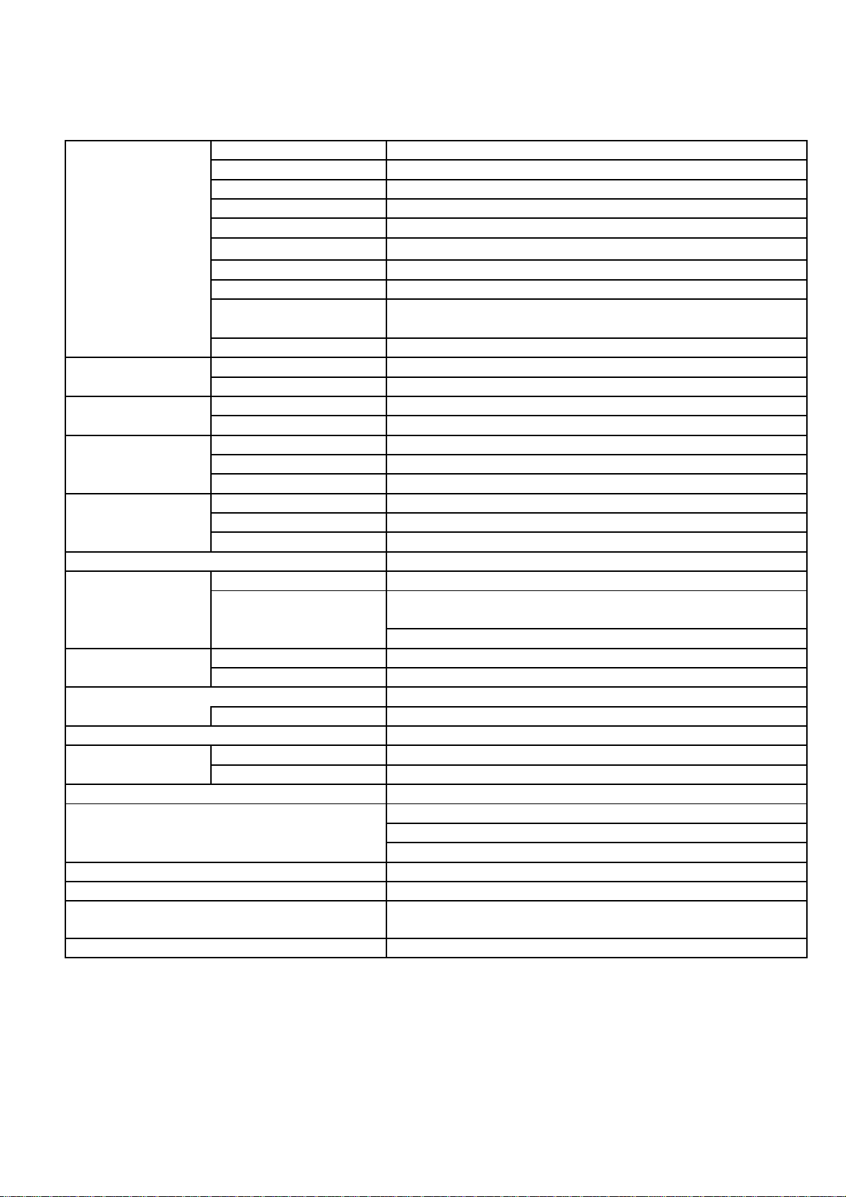
1. MAIN SPECIFICATION
LCD
Panel Type
TFT
Screen Size
15.0"
Pixel Pitch
0.2970 X0.2970 mm
Pixel Format
1,024 X 768
Effective Viewing Area
304.1 X 228.1 mm
Brightness 200 cd/m
2
Response Time
40 ms
Contrast
350 : 1
Viewing Angle
Up:55, Down:65, Right:70, Left:70 deg.
(Contrast Ratio:5)
Color
16.77 million
Back Light
Type
CCFL
No.
2 pcs
Synchronization
Horizontal
24.8 - 60.2 kHz
Frequencies
Vertical
60.0 - 75.0 Hz
Input Signal
System
Analog RGB, Video 0.7Vp-p
Input Impedance
75 ohm
Sync. Type/Level
Separate TTL (+/-)
Audio
Line in
Stereo (Mini Jack X 1)
Headphone
Stereo (Mini Jack X 1)
Speaker
Stereo (0.2W X 2)
Video
15PIN MINI D-SUB
External Control
Switch/Volume
Brightness, Power Switch, Audio Volume
Auto Adjust, Contrast, Horizontal Size, Focus, Horizontal
Language :English, German, French, Spanish
Environment
Temperature
Operating : 5 to 35deg. Storage : -20 to 60deg.
Humidity
30 - 85% RH (Non Condensing)
Power Supply (AC Adapter)
Input : AC 115 - 240V Output : DC12V
GI40-US1225
Power Consumption
30W (Standby : 5W max.)
Physical
Dimensions (WXHXD)
399 X 412 X 199 mm
Weight
4.5kg
Power Management
VESA DPMS
USB HUB
USB standard Rev. 1.1
Self-Powered/Bus Powered
Upstream X 1, Downstream X 3
Tilt/Swivel
Up 20 deg., Down 0 deg., / Swivel Function
Plug & Play
DDC1, DDC2B (VESA Standard)
Auto Display Adjustment, Digital Smoothing Full Screen
Accessories
AC Adapter & Cord, RGB Cable, Audio Cable, USB Cable
On-Screen Display
Position, Vertical Position, Color, Recall, Black level
Other Features
Model Name
Expansion
- 3 -
Page 5
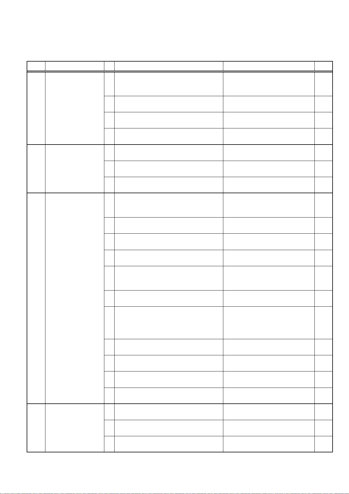
2. TROUBLESHOOTING
Check the following for troubles of LCD monitor.
No. Symptom Check Points Treatments Class
Check AC outlet, AC cord, DC
No Picture with
1
Power Indicator OFF
No Picture with
Power Indicator in
2
Amber
No Picture with
Power Indicator in
3
Green
No Picture with
Power Indicator
4
blinking in Green
1 Is the Power "ON" to a LCD Monitor ?
2 Is an AC Adapter defective?
Is the wire harness between main PCB
3
and DC IN PCB secured firmly ?
Is the Power Supply circuit on main
4
PCB defective ?
1 Is the Power "ON" to a Computer ?
2 Is a computer standing by ?
Is the Image Processing circuit on
3
main PCB defective ?
Is a screen saver programming
1
running ?
2 Is a signal cable connected securely ?
Disconnected a signal cable ? or Bent
3
a terminal pin ?
Is the computer's signal timing not
4
agreeable to the LCD's specification ?
Is the wire harness between Inverter
5
PCB and a LCD module secured firmly
?
Is the wire harness between main PCB
6
and Inverter PCB secured firmly ?
Is the wire harness between main PCB
and SW/LED PCB or main PCB and
7
Brightness control volume connected
securely ?
Is the Brightness control volume
8
defective ?
9 Is the LCD module defective ?
10 Is the Inverter unit defective ?
Is the display circuit on main PCB
11
defective ?
1 Is a computer standing by ?
2 Is a signal cable connected securely ?
Disconnected a signal cable ? or Bent
3
a terminal pin ?
Jack and Power switch for a
LCD monitor
Replace an AC Adapter with the
new one
Check the connection B
Replace the main PCB with the
new one
Check the Power Supply for a
Computer
Be out of standing by condition,
by operating to a computer
Replace the main PCB with the
new one
Press any key or touch the
mouse, to end the screen saver
program
Check the connection of a signal
cable
Replace a signal cable with the
new one
Adjust the computer's signal
timing, if possible
Check the connection of wire
harness
Check the connection of wire
harness
Ensure the connection of a wire
harness
Replace the Volume PCB with
new one, and check the screen
Replace a LCD module with the
new one
Replace an Inverter unit with the
new one
Replace the main PCB with the
new one
Be out of standing by condition,
by operating to a computer
Check the connection of a signal
cable
Replace a signal cable with the
new one
A
B
B
A
A
B
A
A
C
A
B
B
B
B
B
B
B
A
A
C
- 4 -
Page 6

No. Symptom Check Points Treatments Class
White/Grey on
whole
5
screen(Nothing on
screen)
Is the wire harness between main PCB
1
and LCD module secured firmly ?
2 Is the LCD module defective ?
3 Is the main PCB defective ?
Check the connection of wire
harness
Replace a LCD module with the
new one
Replace the main PCB with the
new one
B
B
B
6
Dark screen
Screen's display
7
range is incorrect
8
Screen is distorted
Part of colors(R/G/B)
is not displayed.
9
Black line appears in
vertically
No sound
10
Is the wire harness between inverter
1
and a LCD module secured firmly ?
Is the wire harness between one of
2
inverters and main PCB secured firmly
?
Is the display circuit on main PCB
3
defective ?
Is the adjustment for screen performed
1
correctly ?
Is the output level on image from a
2
computer not agreeable to LCD's
specification ?
Ensure the connection of a wire
harness
Ensure the connection of a wire
harness
Replace the main PCB with the
new one
Adjust the screen correctly A
Check the specification of a
computer
Set the size of screen
3 Is the size of screen set correctly ?
again(refer to User's Manual for
computer)
Is the adjustment for screen performed
1
correctly ?
2 Is a signal cable connected securely ?
Adjust the screen correctly A
Check the connection of a signal
cable
3 Is a sigil cable extended ? Don't extend a signal cable A
Is the output level on image from a
4
computer not agreeable to LCD's
specification ?
Is the Image Processing circuit on
5
main PCB defective ?
1 Is a signal cable connected securely ?
Is the connection between main PCB
2
and a LCD module securely ?
Is the Image Processing circuit on
3
main PCB defective ?
Is the audio cable connected securely?Ensure the connection of the
1
Is the position of audio volume at the
2
minimum position ?
Is the volume setting for an audio
3
equipment adequately ?
Is the wire harness between main PCB
4
and Audio PCB securely ?
Is the wire harness between Audio
5
PCB and Volume PCB securely ?
Check the specification of a
computer
Replace the main PCB with the
new one
Check the connection of a signal
cable
Check the connector B
Replace the main PCB with the
new one
audio cable
Set the audio volume at the
appropriate position
Refer to the user's manual for an
audio equipment
Ensure the connection of a wire
harness
Ensure the connection of a wire
harness
B
B
B
C
A
A
C
B
A
B
A
A
A
B
B
- 5 -
Page 7

No. Symptom Check Points Treatments Class
Provide AC power to a LCD
connect an AC Adapter to a LCD
A It is possible to treated by end-user
B It might be possible to treat by end-user in some case.
C It must be treated by Professional Technical Staff
10
No sound
USB devise does not
11
work(a PC does not
detect an USB Hub)
USB devise does not
work(a PC does not
12
detect an USB
devise)
Is the wire harness between Audio
6
PCB and DC IN PCB securely ?
Is the wire harness to speakers
7
securely ?
8 Is the Audio PCB defective ?
Is a LCD monitor connected to an USB
1
devise securely with USB cable ?
Upon a timing, a PC does not detects
2
an USB Hub
Upon a PC's OS or version, a PC
3
cannot control USB devise
Is the wire harness between main PCB
4
or DC IN PCB and USB PCB secured
firmly ?
Is the wire harness between USB PCB
5
and a relay PCB for USB secured
firmly ?
6 Is the USB PCB defective ?
Is a LCD monitor connected to an USB
1
devise securely with USB cable ?
Upon a timing, a PC does not detects
2
an USB devise
Is the driver software for a USB devise
3
loaded correctly ?
4 Is the USB PCB defective ?
Ensure the connection of a wire
harness
Ensure the connection of a wire
harness
Replace the Volume PCB with
new one, and check the screen
Ensure the connection of the
USB cable
Reinstall the USB cable A
Refer to the user's manual for a
PC and OS. Ensure a PC
supports USB
Ensure the connection of a wire
harness
Ensure the connection of a wire
harness
Replace the USB PCB with new
one
Ensure the connection of the
USB cable
Reinstall the USB cable A
Refer to the user's manual for an
USB devise. Reload it to a PC.
Replace the USB PCB with new
one
B
B
B
A
A
B
B
B
A
A
B
A connected USB
devise in self-
13
powered does not
work
Is the USB devise in self-powered
1
connected with a LCD Monitor AC is
not providing ?
Is the connection between the USB
2
PCB and DC IN PCB secured firmly ?
3 Is the USB PCB defective ?
- 6 -
Monitor. Check Warning is not
displayed. Refer to the User's
manual for an USB devise,
Ensure the connection B
Replace the USB PCB with the
new one
A
B
Page 8

3. MAINTENANCE
How to remove the major components
(1) Stand Cover
1.Place your fingers in a hollow of the Stand Cover. While pressing the Stand Cover
hollow inside, and pull it your side.
(2) Main unit and Stand
1.Unscrew a Stand at the metal bracket to be secured with a Main unit (4-Screws)
2.Disconnect the USB cable
(3) Cabinet
1.Unscrew a Rear Cabinet (6-Screws)
2.While pressing the top portion of a Front Cabinet, pull the hooks your side
3.Disconnect the lead wires to Switch/LED PCB
(4) Switch/LED PCB and Brightness Volume PCB
1.Unscrew the Switch/LED PCB and Brightness Volume (6-Screws)
2.Disconnect the leads wire from Switch/LED PCB
3.Disconnect the leads wire from Brightness Volume PCB
(5) LCD Panel
1.Unscrew a LCD Panel (4-Screws)
2.Holding a LCD Panel up, then disconnect two lead wires from Inverter unit
3.Disconnect two FPC connectors from the Main Logic PCB
(6) Inverter Units
1.Disconnect lead wires to the Main Logic PCB
2.Unscrew the Inverter PCB (4-Screws)
(7) Main Logic PCB
1.Disconnect a RGB cable
2.Unscrew the shield plate over the Main Logic PCB (5-Screws)
3.Remove the Inverter connector, DC connector and Switch/LED connector
4.Unscrew a metal bracket to be secured with RGB connector (2-Screws)
(8) DC-IN PCB
1.Unscrew the DC-IN PCB (2-Screws)
2.Disconnect the connectors from a Power Switch, the DC connector and the
Audio/USB connector
(9) Power Switch
1.While pressing the hook of a Power Switch, and pull it out
(10) USB PCB in a Stand
1.Unscrew a Stand Base (4-Screws)
2.Remove a Stand Base
3.Unscrew the USB PCB (3-Screws)
4.Disconnect the lead wires from Audio/USB-IN PCB
5.Disconnect the lead wires from AUDIO PCB
(11) AD-IN PCB
1.Unscrew the AD-IN PCB (2-Screws)
2.Disconnect the lead wires from USB PCB
3.Disconnect the lead wires from Audio/USB PCB
(12) Audio PCB
1.Unscrew the Audio PCB (3-Screws)
2.Disconnect the lead wires from Audio/USB-IN PCB
3.Disconnect the lead wires from USB PCB
4.Disconnect the lead wires from Audio/USB-IN PCB
5.Disconnect the lead wires from Speaker (Right/Left)
- 7 -
Page 9

4. BLOCK DIAGRAM
TFT
XGA LCD PANEL
PANEL CONTROL
ROM
MICRO CONTROLLER
POWER SUPPLY
CHEETAH3
CRC
DB15
Vsync
PLL
SAMPLING
Hsync
- 8 -
Red
VIDEO
Green
PRE-AMP
Blue
Page 10

5. Connection Diagram
er
t
Invert
Uni
HOT1
CN3
1
2
3
N.C.
1
COLD
HOT1
CN2
1
2
3
N.C.
1
COLD
AC
Plug
CN1
1
2
3
4
5
AC
Adapter
GND
+12V
VR2
VR1
ON(=5V)
1
2
3
4
5
Power Switch
VCC
-DATA
+DATA
D
GND
F_GN
USB Device
ND
VCC
GND
-DATA
+DATA
F_G
ND
VCC
GND
-DATA
+DATA
F_G
P3
30
29
28
27
26
25
24
23
22
21
20
19
18
17
16
15
14
13
12
11
10
9
8
7
6
5
4
3
2
1
h
45
44
43
42
41
40
39
38
37
36
35
34
33
32
31
30
29
28
27
TFT 15-inc
Liquid Crystal
Display
26
25
24
23
22
21
20
19
18
17
16
15
14
13
12
11
10
9
8
7
6
5
4
3
2
1
VRB2
VRBC
VRB1
2
GND
1
12V
LED_G
VCC
LED_R
GND
UP
DOWN
SEL
MENU
3
CN20
01
J1
HEADPHONE OUT
VR2
VRC
VR1
2
1
P7
30
RE0
29
RE1
28
RE2
27
RE3
26
GND
25
RE4
24
RE5
23
RE6
22
RE7
21
GND
20
GE0
19
GE1
18
GE2
17
GE3
16
GND
15
GE4
14
GE5
13
GE6
12
GE7
GND
BE0
BE1
BE2
BE3
GND
BE4
BE5
BE6
BE7
GND
TEST
TEST
TEST
VCC
VCC
RO0
RO1
RO2
RO3
GND
RO4
RO5
RO6
RO7
GND
GO0
GO1
GO2
GO3
GND
GO4
GO5
GO6
GO7
GND
BO0
BO1
BO2
BO3
GND
BO4
BO5
BO6
BO7
GND
NC
GND
HD
GND
VD
GND
DENA
GND
DCLK
GND
P10
11
10
9
8
7
6
5
4
3
2
1
45
44
43
42
41
40
39
38
37
36
35
34
33
32
31
30
29
28
27
26
25
24
23
22
21
P9
20
19
18
17
16
15
14
13
12
11
10
9
8
7
6
5
4
3
2
1
Analogue Interface P.C.B
SANDDUNE2
3
2
1
P5
8
7
6
5
4
3
2
1
P2
P6
8
7
6
5
4
3
2
9
15
14
13
1
12
11
10
IN
DC
2
CN20
N.C.
N.C.
1
2
J201
1
CN20
.B
P.C
1
2
1
2
1
2
GND
12V
2
CN10
P.C.B
MUTE
4
3
2
1
12V
GND
1
2
1
2
3
CN2
CN1
VR2
Audio
1
2
3
4
1
+
CN10
R-
UTL+
SPOUTL-
SPO
SPOUT
SPOUTR
VCC
1
CN3
-DATA
GND
L
GND
R
2
+DATA
3
CN50
1
D
GND
F_GN
4
Frame
2
3
D
VCC
VCC
GND
-DATA
+DATA
F_GN
1
2
3
4
Frame
CN4
CN5
.B
B
US
P.C
CN2
1
2
3
4
VCC2
+DATA2
GND
-DATA2
GND
4
1
2
3
4
CN20
4
3
1
2
1
CN20
3
1
2
3
4
Frame
CN20
ND
GND
+DATA
-DATA
VCC
Port
F_G
USB Upstream
1
5
5
-DATA
2
2
CN20
+DATA
3
GND
4
D
F_GN
Frame
IO
.B
nnector
USB/AUD
Co
P.C
LINE IN
Speaker (R)
Speaker (L)
N.C.
5
N.C.
4
2
3
3
VRB2
2
2
VRBC
1
CN20
13
12
11
10
9
8
7
6
5
4
3
1
h / LED
2
1
CN20
Switc
VRB1
C.B
P.
VR1
1
CN6
Volume
C.B
Brightness
P.
C
LK
GND
GND
GND
GND
GND
HSYNC
GND
DDDA
N.C.
N.C.
BLUE
GREEN
RED
ND
GND
VCC
+DATA
-DATA
C
LK
DDC
HSYNC
N.C.
N.C.
BLUE
N.C.
GND
GND
GND
VSYN
8
15
7
14
6
13
RED
GND
GND
DDDA
GREEN
5
12
4
11
3
10
2
9
1
F_G
1
2
3
4
Frame
DDC
VSYN
puter
VGA
Port
Com
USB
Downstream Port
- 9 -
Page 11

6. TABLE OF SIGNAL NAME
Symbol
Signal Name
Location
Notes
RED RED/Analog Video Signal P6-1
GREEN
GREEN/Analog Video Signal
P6-2
BLUE
BLUE/Analog Video Signal
P6-3
DDDA(ID1)
DDC Data
P6-12
HSYNC
Horizontal Synchronizing Signal
P6-13
VSYNC
Vertical Synchronizing Signal
P6-14
DDCK(ID3)
DDC Data Clock
P6-15
BE7
BLUE Data[MSB]-Even
P10-2
POLARITY +
BE6
BLUE Data
P10-3
POLARITY +
BE5
BLUE Data
P10-4
POLARITY +
BE4
BLUE Data
P10-5
POLARITY +
BE3
BLUE Data
P10-7
POLARITY +
BE2
BLUE Data
P10-8
POLARITY +
BE1
BLUE Data
P10-9
POLARITY +
BE0(EVEN)
BLUE Data[LSB]-Even
P10-10
POLARITY +
GE7
GREEN Data[MSB]-Even
P10-12
POLARITY +
GE6
GREEN Data
P10-13
POLARITY +
GE5
GREEN Data
P10-14
POLARITY +
GE4
GREEN Data
P10-15
POLARITY +
GE3
GREEN Data
P10-17
POLARITY +
GE2
GREEN Data
P10-18
POLARITY +
GE1
GREEN Data
P10-19
POLARITY +
GE0(EVEN)
GREEN Data[LSB]-Even
P10-20
POLARITY +
RE7
RED Data[MSB]-Even
P10-22
POLARITY +
RE6
RED Data
P10-23
POLARITY +
RE5
RED Data
P10-24
POLARITY +
RE4
RED Data
P10-25
POLARITY +
RE3
RED Data
P10-27
POLARITY +
RE2
RED Data
P10-28
POLARITY +
RE1
RED Data
P10-29
POLARITY +
RE0(EVEN)
RED Data[LSB]-Even
P10-30
POLARITY +
DCLK
Data Clock
P9-2
DENA
Data Enable
P9-4
POLARITY -
VD
Vertical Synchronizing Signal
P9-6
POLARITY +
HD
Horizontal Synchronizing Signal
P9-8
POLARITY +
BO7
BLUE Data[MSB]-Odd
P9-12
POLARITY +
BO6
BLUE Data
P9-13
POLARITY +
BO5
BLUE Data
P9-14
POLARITY +
BO4
BLUE Data
P9-15
POLARITY +
BO3
BLUE Data
P9-17
POLARITY +
BO2
BLUE Data
P9-18
POLARITY +
BO1
BLUE Data
P9-19
POLARITY +
BO0
BLUE Data[LSB]-Odd
P9-20
POLARITY +
GO7
GREEN Data[MSB]-Odd
P9-22
POLARITY +
GO6
GREEN Data
P9-23
POLARITY +
GO5
GREEN Data
P9-24
POLARITY +
GO4
GREEN Data
P9-25
POLARITY +
GO3
GREEN Data
P9-27
POLARITY +
GO2
GREEN Data
P9-28
POLARITY +
GO1
GREEN Data
P9-29
POLARITY +
- 10 -
Page 12

Symbol
Signal Name
Location
Notes
GO0 GREEN Data[LSB]-Odd P9-30 POLARITY +
RO7
RED Data[MSB]-Odd
P9-32
POLARITY +
RO6
RED Data
P9-33
POLARITY +
RO5
RED Data
P9-34
POLARITY +
RO4
RED Data
P9-35
POLARITY +
RO3
RED Data
P9-37
POLARITY +
RO2
RED Data
P9-38
POLARITY +
RO1
RED Data
P9-39
POLARITY +
RO0
RED Data[LSB]-Odd
P9-40
POLARITY +
TEST
Test Signal Out(*)
P9-43
TEST
Test Signal Out(*)
P9-44
TEST
Test Signal Out(*)
P9-45
+12V
for Output Voltage (+)
P3-1
VR1,2
for Contrast Volume
P3-3,4
ON=5V
for Back-Light Control
P3-5
H: Light ON
VR1,2
Brightness Control
P5-1,3
VRC
Brightness Control
P5-2
MENU
Menu Key Input
P2-1
SEL
Select Key Input
P2-2
DOWN
Down Key Input
P2-3
UP
Up Key Input
P2-4
LED R
LED/RED, Control Signal
P2-6
LED G
LED/GREEN, Control Signal
P2-8
* : This terminal must be opened at System-side.
- 11 -
Page 13

20
19
21
Page 14

CAUTION
Parts marked as Are very important to secure safety.
In case of replacement, it is required to use designted parts for safety.
7-2 Parts List
REF NO.
PART No.
DESCRIPTION
Q'ty
NOTES
OUTER
(632 880 4986)
OUTER CARTON
1
(632 613 4436)
LABEL, BARCODE
1
INDIVIDUAL
(632 834 2815)
STYRO-FOAM CUSHION, R
1
(632 834 2839)
STYRO-FOAM CUSHION, L
1
(632 834 2891)
PAD, ACCESSORY
1
(632 297 9901)
POLYETHYLENE BAG, 450X425X380
1
(632 607 4824)
POLYETHYLENE BAG, L180X270
1
(632 298 2376)
POLYETHYLENE BAG, 120X320
1
(632 607 4794)
POLYETHYLENE BAG, L120X230
2
(632 840 4056)
PAD, CUSHION
1
(632 840 3639)
PAD
1
ACCESSORY
(632 885 5698)
INSTRUCTION MANUAL, ENGLISH
1
(632 887 4460)
INSTRUCTION MANUAL, GERMANY
1
CABINET1
1
(632 888 6302)
CABINET ASS'Y, 150AT
1
8
(632 888 6319)
BOTTOM LID ASS'Y, 150T
1
18
(632 880 4993)
RATING PLATE
1
CHASSIS
4
(632 888 6333)
SHIELD CASE ASS'Y
1
STAND
10
(632 888 6388)
STAND ASS'Y
1
9
(632 832 1957)
COVER, STAND
1
CHASSIS ELC.
3
(632 888 6326)
LIQUID CRYSTAL DIS. ASS'Y
12(632 825 8291)
FFC ASS'Y
1
7
(632 888 6364)
DC-AC INVERTER ASS'Y
1
16
(632 880 5488)
AC ADAPTER
1
17
(632 873 0926)
AC CORD
1
11
(632 850 6095)
POWER SWITCH ASS'Y
112(632 888 8689)
WIRE HARNESS ASS'Y
1
13
(632 872 9494)
VGA CABLE, 1.5M
1
14
(632 872 9715)
USB CABLE, 1.5M
1
15
(632 883 7083)
AUDIO CABLE, 1.5M
1
PC BOARD 1
5
(632 888 6340)
PW BOARD ASS'Y, MAIN
1
PC BOARD 4
6
(632 888 6357)
PW BOARD ASS'Y, DC-IN
1
PC BOARD 5
20
(632 893 0456)
PW BOARD ASS'Y, AUDIO
1
PC BOARD 6
21
(632 893 0463)
PW BOARD ASS'Y, AUDIO/USB-IN
1
PC BOARD 7
19
(632 893 0470)
PW BOARD ASS'Y, USB
1
FOR MONITOR
FOR USER'S GUIDE
FOR RGB CABLE
FOR AC ADAPTER, AC CORD
- 13 -
Page 15

APPENDIX
Version of Firmware
The Version of Firmware is displayed on screen.
Turn the Power Switch to ‘OFF’. While pressing of the [SELECT] button, turn the Power
Switch to ‘ON’.
- 14 -
 Loading...