

Sanyo LCE-32R83DT-C Schematic
FILE NO.
SERVICE MANUAL
LED-LCD TV
LCE-32R83DT(C)
PRODUCT CODE No.
PRODUCT CODE No.
1 682 352 40: PAL/SECAM
-B/G, D/K, I
NTSC(AV)
INPUT
3
2
1
6
5
4
8
9
7
FREEZE
0
SLEEP
DISPLAY
ENTER
EXIT
MENU
MUTE
VOL CH
FAVORITE
TTX
FUNCTION
ZOOM
MIX
AUTO/STEREO
INDEX
PICTURE
SUBTITLE
SOUND
TEXT/USB
REFERENCE No.:SM0915247

CONTENTS
Safety precautions………………………………………………………………………..…
Alignment instructions …………………………….…….…………………………………
Software upgrade instructions ..................................................................................
Working principle analysis……………………………….………….…………...............
Block diagram…………………………………..………………………………….…………
IC block diagram………………………………………………………………………..……
Wiring diagram …………………………………………………………………………….
Troubleshooting flow chart ………………………………………………………………..……
Schematic diagram…………………………………………………………………………
APPENDIX-A: Assembly list
APPENDIX-B: Exploded View
Assembling the Stand
WALL MOUNTING INSTRUCTIONS
3
5
11
16
17
18
32
33
36

Attention: This service manual is only for service personnel to take reference with. Before
servicing please read the following points carefully.
Safety precautions
1. Instructions
Be sure to switch off the power supply before replacing or welding any components or
inserting/plugging in connection wire. Anti static measures must be taken (throughout the entire
production process!):
a) Do not touch here and there by hand at will;
b) Be sure to use anti static electric iron;
c) It’s necessary for the welder to wear anti static gloves.
Please refer to the part list before replacing components that have special safety requirements.
Do not replace with different components with different specs and type at will.
2. LCD servicing precautions
2.1 Screens are different from one model to another and therefore not interchangeable. Be sure to
use the screen of the original model for replacement.
2.2 Be sure to take proper measures in protecting yourself and the machine when testing
the system in the course of normal operation or right after the power is switched off. Please do not
touch the circuit or the metal part of the module that is in operation mode. Relevant operation is
possible only one minute after the power is switched off.
2.3 Do not use any adapter that is not identical with the TV set. Otherwise it will cause fire or
damage to the set.
2.4 Never operate the set or do any installation work in bad environment such as wet bathroom,
laundry, kitchen, or nearby fire source, heating equipment and devices or exposure to sunlight etc.
Otherwise bad effect will result.
2.5 If any foreign substance such as water, liquid, metal slices or other matters happens to fall into
the module, be sure to cut the power off immediately and do not move anything on the module lest
it should cause fire or electric shock due to contact with the high voltage or short circuit.
2.6 Should there be smoke, abnormal smell or sound from the module, please shut the power off
at once. Likewise, if the screen is not working after the power is on or in the course of operation,
the power must be cut off immediately and no more operation is allowed under the same
condition.
2.7 Do not pull out or plug in the connection wire when the module is in operation or just after the
power is off because in this case relatively high voltage still remains in the capacitor of the driving
circuit. Please wait at least one minute before the pulling out or plugging in the connection wire.
2.8 When operating or installing LCD please don’t subject the LCD components to bending,
twisting or extrusion, collision lest mishap should result.
2.9 As most of the circuitry in LCD TV set is composed of CMOS integrated circuits, it’s necessary
to pay attention to anti statics. Before servicing LCD TV make sure to take anti static measure and
ensure full grounding for all the parts that have to be grounded.
2.10 There are lots of connection wires between parts behind the LCD screen. When servicing or
moving the set please take care not to touch or scratch them. Once they are damaged the screen
would be unable to work and no way to get it repaired.
If the connection wires, connections or components fixed by the thermotropic glue need to
disengage when service, please soak the thermotropic glue into the alcohol and then pull them
out in case of dagmage.
2.11 Special care must be taken in transporting or handling it. Exquisite shock vibration may lead
to breakage of screen glass or damage to driving circuit. Therefore it must be packed in a strong
case before the transportation or handling.
2.12 For the storage make sure to put it in a place where the environment can be controlled so as
to prevent the temperature and humidity from exceeding the limits as specified in the manual. For
prolonged storage, it is necessary to house it in an anti-moisture bag and put them altogether in
one place. The ambient conditions are tabulated as follows:
Temperature Operation range +5 ~ +35 oC
Storage range -20 ~ +60 oC
Humidity Operation range 20% ~ 80%
Storage range 10% ~ 90%
2.13 Display of a fixed picture for a long time may cause a permanent after-image on the screen,
as commonly called “ghost shadow”. The degree of the after-image varies with the maker of LCD
screen. This phenomenon doesn’t represent failure. This “ghost shadow” may remain in the
picture for a period of time (several minutes). But when operating it please avoid displaying still
picture in high brightness for a long time.
3. Installation precautions
3.1 The front panel of LCD screen is made of glass. When installing it please make sure to put it in
place.
3.2 For service or installation it’s necessary to use specified screw lest it should damage the
screen.
3.3 Be sure to take anti dust measures. Any foreign substance that happens to fall down between
the screen and the glass will affect the receiving and viewing effect
3.4 When dismantling or mounting the protective partition plate that is used for anti vibration and
insulation please take care to keep it in intactness so as to avoid hidden trouble.
3.5 Be sure to protect the cabinet from damage or scratch during service, dismantling or
mounting.
Adjustment Instructions
1 Safety Instructions
1.1 Power supply must be cut off when replacing or welding any component or inserting / pulling out
connective lines;
1.2 Anti-electrostatic measures must be carried out during the whole producing processes!
a) Do not touch IC by hands at will;
b) Use anti-electrostatic iron;
c) Welder must wear anti-electrostatic glove;
1.3 Replacing any component with special safety requirement must refer to component list without
changing its specification and model at will.
1.4 Power supply voltage must be ~(100-240) V±10% 50 Hz.
2 Adjustment Equipments
VG-848 (YPbPr, VGA signal generator)
VG-849 (HDMI signal generator)
CA-210
3 Adjustment Processes
3.1 Power voltage test
According to the wiring diagram ‘9232ME7001JL’, connect power board assembly, data
processing assembly, IR/Key board assembly correctly, supply with power, press button standby
to turn on the TV set.
3.11 Model LC-32MEXX
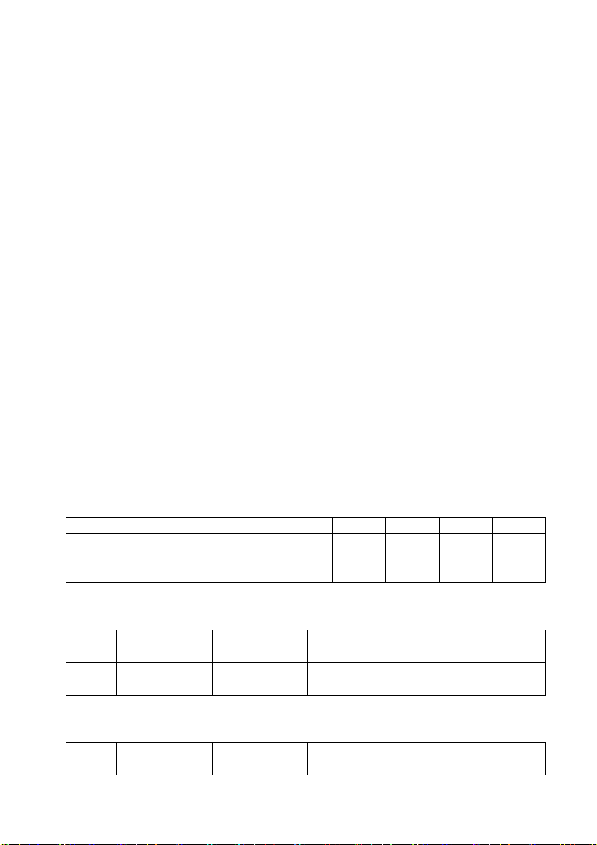
Test voltage of X301 each pin on power board in turn shown as Table 1:
Table 1 Voltage of X301 each pin
X301
Min. (V) 0 11.3 0 4.85 4.85 4.85 3.25 4.85
Typical(V) 0 12.0 0 5.00 5.00 5.00 3.30 5.00
Max. (V) 0 12.6 0 5.35 5.35 5.35 3.35 5.07
Pin 1
2、3 4、5
6 7 8 9 10
3.12 Model LE-32/42MEXX and LC-39/46/50MEXX
Test voltage of X301 each pin on power board in turn shown as Table 2:
Table 2 Voltage of X301 each pin
Pin 1、2 3、4 5、6 7、8
X301
Min. (V) 11.3 0 11.3 0 4.85 4.85 4.85 3.25 4.85
Typical(V) 12.0 0 12.0 0 5.00 5.00 5.00 3.30 5.00
Max. (V) 12.6 0 12.6 0 5.35 5.35 5.35 3.35 5.07
9 10 11 12 13
3.13 Model LE-46/55MEXX
Test voltage of X301 each pin on power board in turn shown as Table 3:
Table 3 Voltage of X301 each pin
Pin 1、2 3、4 5、6 7、8
X301
Min. (V) 24.3 0 11.3 0 4.85 4.85 4.85 3.25 4.85
9 10 11 12 13
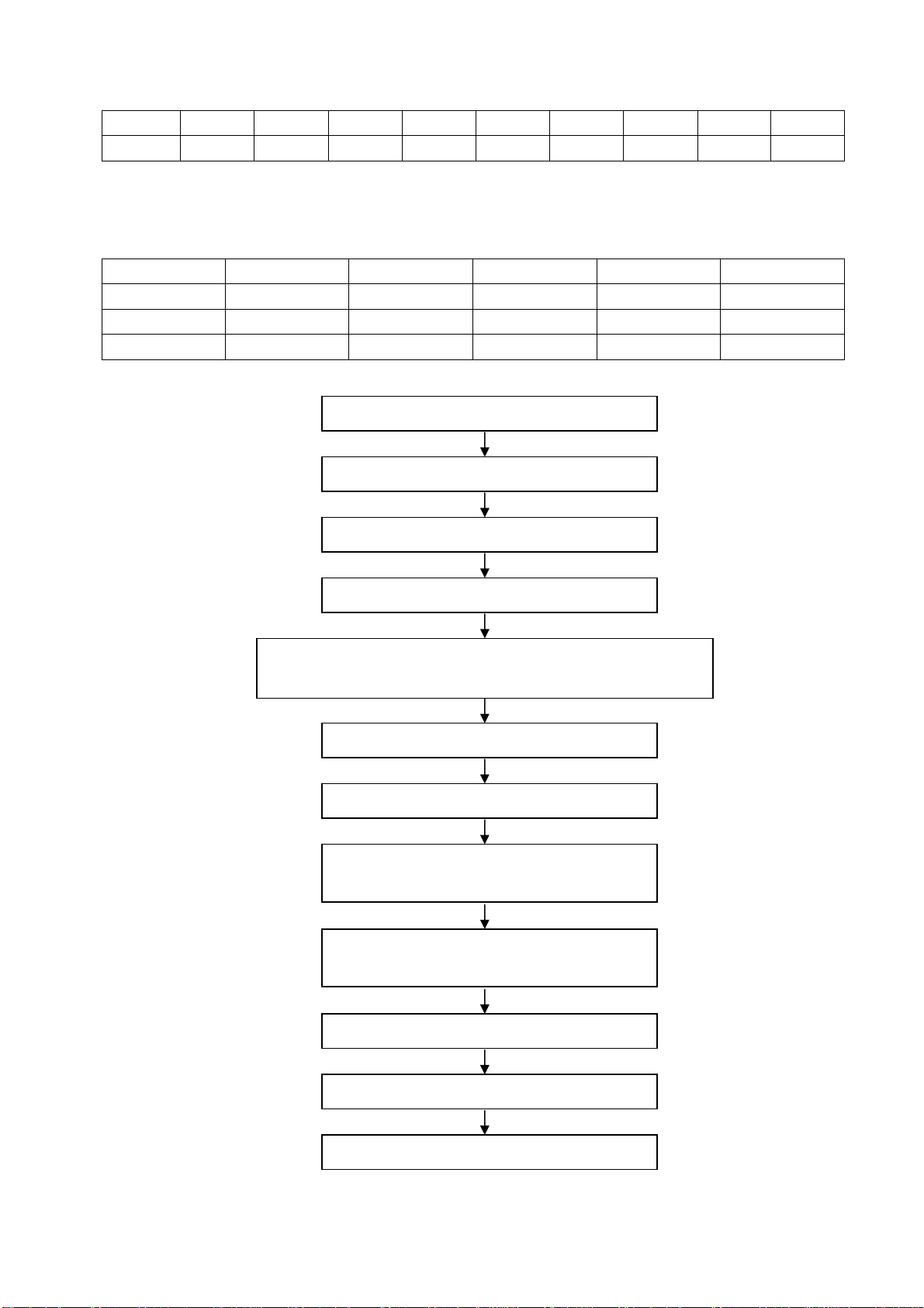
Typical(V) 24.0 0 12.0 0 5.00 5.00 5.00 3.30 5.00
Max. (V) 23.6 0 12.6 0 5.35 5.35 5.35 3.35 5.07
3.14 Model LC-29ME70/LE-32ME77 for domestic market, all-in-one model LE-29/32/39ME83,
model LC-24ME70/LC-24ME77
Test voltage of X301 each pin on power board in turn shown as Table 3(a):
Table 3(a) Voltage of X301 each pin
X301
Min. (V) 11.3 0 3.25 4.85 4.85
Typical(V) 12.0 0 3.30 5.00 5.00
Max. (V) 12.6 0 3.35 5.35 5.35
Pin 1、2 3、4
5 6 7
3.2 Adjustment flow as Fig. 1:
Check if DDC、FLASH has been written?
Produce data processing board on line.
General assembly and combined adjustment
White balance adjustment
Input central signal, check TV function (omitted channel, analog
parameters control, etc. ), check earphone, speakers output.
Input AV signal, check relevant functions.
Input HDMI signal (mode), check YPbPr functions.
Input VGA signal, check display and all functions
(such as analog parameter), H/V center, etc..
Input HDMI signal, check display and all functions
(such as analog parameter), H/V center, etc..
Input USB signal, check relevant functions.
Default settings before shipment
Check accessory and packing
Fig. 1 Adjustment flow chart

4 Adjustment Instructions
4.1 The unit adjustments
4.1.1 According to the wiring diagram “9232ME7001JL”, connect power/backlight board assembly,
data processing assembly, IR/Key board assembly correctly, supply with power, turn on the TV set.
Check display.
4.1.2 Factory menu instruction
a) Press key “INPUT”, press digital keys “2、5、8、0” in turn to enter into primary factory menu;
b) Press keys “” and “” to move cursor to each page of primary factory menu, then press
key “ENTER” to enter into submenu page;
c) Press keys “” and “” to move cursor upward or downward within any one page;
d) Press keys “” and “” to do adjustment when move cursor to one item;
e) Press key “MENU” to exit submenu page of factory menu sequentially; The cursor must
focus on the first item when pressing key “MENU” to exit some of the submenu page.
f) Factory menu item: Aging Mode to be used for aging the TV set when the option is “On”;
press any key on key board to exit aging mode during the aging process;
g) Factory menu item: Othersetting → Power on mode:
‘On’: to turn on the TV set with one step;
‘Off’: to turn on the TV set with two steps;
‘Last’: to keep the last power-off state when power on the TV set again;
4.2 White balance adjustment
4.2.1 Before adjustment
The TV set should be working above 30 minutes to be in a stabler state before adjustment. Use
CA-210 BBY channel to adjust white balance;
a) VGA channel adjustment
Input square signal (VG848 Timing: 854 (VESA 800
×600/60 Hz), enter into user menu
SETTING→Computer Settings→ AUTO ADJUST to make picture display fully; then input signal
(VG848 PAT: 914), enter into factory menu page ADC ADJUST to perform AUTO ADC until the
prompt “SUCCESS” displays.
b) YPbPr channel adjustment
Input signal (VG848 Timing: 968 (480i/60 Hz),PAT: 918 (100% color bar + gray scale)) ,
enter into factory menu page ADC ADJUST to perform AUTO ADC until the prompt “SUCCESS”
displays.
c) Only Normal color temperature need adjusting for the model. Chromatic coordinates of bright
scale must be set as (△X=±5, △Y=±5), chromatic coordinates of dark scale must be set as (△X=±10,
△Y=±10). Chromatic coordinates of each model are listed as Table 4:
Table 4 Chromatic coordinates of each model
WARM NORMAL COOL
6500K(313、329) 9300K(285、293) 12000K(272、278)

d)BBY:Insignia-Dynex TV Spec Part of chromatic coordinates are listed as Fig. 2:
Fig.2 Chromatic coordinates of white balance
4.2.2 Four groups of white balance adjustments
4.2.2.1 DVI channel adjustment (HDMI,USB channel with the same adjustment method of this one)
Input signal (VG848 Timing: 854,PAT: 921 (16-gray-step)), enter into factory menu page Color
Temp, fix item G-GAIN, adjust items R-GAIN、B-GAIN to set chromatic coordinates of the reversed
th
scale as the date of NORMAL; fix item G-OFFSET, adjust items R-OFFSET、B-OFFSET to set
4
th
chromatic coordinates of the 4
scale as the date of NORMAL; adjust items R-GAIN、B-GAIN and
R-OFFSET、B-OFFSET repeatedly as above until chromatic coordinates of both gray scales are the
date of NORMAL;
Check if chromatic coordinates of WARM is (313、329), if not, adjust items R GAIN / B GAIN /
R OFF/ B OFF to be up to the requirements and then save the date.
Check if chromatic coordinates of COOL is (272、278), if not, adjust items R GAIN / B GAIN /
R OFF/ B OFF to be up to the requirements and then save the date.
4.2.2.2 VGA channel adjustment
Input signal (VG848 Timing: 854,PAT: 921 (16-gray-step)), enter into factory menu page Color
Temp, fix item G-GAIN, adjust items R-GAIN、B-GAIN to set chromatic coordinates of the reversed
th
scale as the date of NORMAL; fix item G-OFFSET, adjust items R-OFFSET、B-OFFSET to set
4
th
chromatic coordinates of the 4
scale as the date of NORMAL; adjust items R-GAIN、B-GAIN and
R-OFFSET、B-OFFSET repeatedly as above until chromatic coordinates of both gray scales are the
date of NORMAL;
Check if chromatic coordinates of WARM is (313、329), if not, adjust items R GAIN / B GAIN /
R OFF/ B OFF to be up to the requirements and then save the date.
Check if chromatic coordinates of COOL is (272、278), if not, adjust items R GAIN / B GAIN /
R OFF/ B OFF to be up to the requirements and then save the date.
4.2.2.3 YPbPr channel adjustment
Input signal (VG848 Timing: 968,PAT: 921 (16-gray-step)), enter into factory menu page Color
Temp, fix item G-GAIN, adjust items R-GAIN、B-GAIN to set chromatic coordinates of the reversed
th
scale as the date of NORMAL; fix item G-OFFSET, adjust items R-OFFSET、B-OFFSET to set
4
th
chromatic coordinates of the 4
scale as the date of NORMAL; adjust items R-GAIN、B-GAIN and
R-OFFSET、B-OFFSET repeatedly as above until chromatic coordinates of both gray scales are the
date of NORMAL;
Check if chromatic coordinates of WARM is (313、329), if not, adjust items R GAIN / B GAIN /
R OFF/ B OFF to be up to the requirements and then save the date.
Check if chromatic coordinates of COOL is (272、278), if not, adjust items R GAIN / B GAIN /
R OFF/ B OFF to be up to the requirements and then save the date.
4.2.2.4 AV channel adjustment(TV channel with the same adjustment method of this one)
Input signal (VG848 Timing: 969,PAT: 921 (16-gray-step)), enter into factory menu page Color
Temp, fix item G-GAIN, adjust items R-GAIN、B-GAIN to set chromatic coordinates of the reversed
th
scale as the date of NORMAL; fix item G-OFFSET, adjust items R-OFFSET、B-OFFSET to set
4
th
chromatic coordinates of the 4
th
scale is about 10nit; adjust items R-GAIN、B-GAIN and R-OFFSET、B-OFFSET repeatedly as
4
scale as the date of NORMAL and make sure the brightness of the
above until chromatic coordinates of both gray scales are the date of NORMAL;
Check if chromatic coordinates of WARM is (313、329), if not, adjust items R GAIN / B GAIN /
R OFF/ B OFF to be up to the requirements and then save the date.
Check if chromatic coordinates of COOL is (272、278), if not, adjust items R GAIN / B GAIN /
R OFF/ B OFF to be up to the requirements and then save the date.
5 Function check
5.1 TV functions
Input central signal to RF port, enter into menu Channel first, then search for programs
automatically and check if any program is omitted; check the speakers output and the display.
5.2 AV port
Input AV signal, check the sound and the picture.
5.3 YPbPr/YCbCr port
Input YUV signal from VG848 with formats listed as Table 5 respectively, check the sound and
the display.
Table 5 YUV received signal formats
No. Definition
1 720×480i/59.94 Hz 15.73 59.94 13.50 CEA-770.2-C
2 720×480i/60 Hz 15.75 60 13.51 CEA-770.2-C
3 720×576i/50 Hz 15.62 50 13.50 ITU-R BT.656–4
4 720×480p/59.94 Hz 31.47 59.94 27.00 CEA-770.2-C
5 720×480p/60 Hz 31.50 60 27.03 CEA-770.2-C
6 720×576p/50 Hz 31.25 50 27.00 ITU-R BT.1358
7 1280×720p/50 Hz 37.50 50 74.25 SMPTE 296M
8 1280×720p/59.94 Hz 44.95 59.94 74.18 CEA-770.3-D
9 1280×720p/60 Hz 45.00 60.00 74.25 CEA-770.3-D
10 1920×1080i/50 Hz 28.12 50 74.25 SMPTE 274M
11 1920×1080i/59.94 Hz 33.72 59.94 74.18 CEA-770.3-C
12 1920×1080i/60 Hz 33.75 60.00 74.25 CEA-770.3-C
13 1920×1080p/50 Hz 56.25 50 148.50
14 1920×1080p/59.94 Hz 67.43 59.94 148.35
15 1920×1080p/60 Hz 67.50 60.00 148.50
H.- Freq.
(kHz)
V.- Freq.
(Hz)
Dot pulse Freq.
(MHz)
Note
5.4 VGA port
Input VGA signal from VG848 with formats listed as Table 6 respectively, check the sound and
the display. If H./V. of picture displays abnormally, enter into user menu Setup→VGA Setting→
AUTO to perform calibration automatically to display the picture fully.
Table 6 VGA received signal formats
No. Definition
1 720×400@70 Hz 31.47 70.08 28.32 VGA-T
2 640×480@60 Hz 31.50 60.00 25.18 VGA
3 640×480@72 Hz 37.90 72.00 31.50 VESA
4 640×480@75 Hz 37.50 75.00 31.50 VESA
5 800×600@56 Hz 35.16 56.25 36.00 VESA
6 800×600@60 Hz 37.90 60.00 40.00 VESA Guidelines
7 800×600@75 Hz 48.08 75.00 50.00 VESA
8 1024×768@60 Hz 48.40 60.00 65.00 VESA Guidelines
9 1024×768@70 Hz 56.50 70.00 75.00 VESA
10 1024×768@75 Hz 60.00 75.00 78.75 VESA
11 1280×768@75 Hz 60.30 75.00 102.25 VESA
12 1360×768@60 Hz 47.70 60.00 85.5 VESA
13 1280×1024@60 Hz 64.00 60.00 108.0 VESA (FHD panel)
14 1280×1024@75 Hz 80.00 75.00 135.0 VESA (FHD panel)
15 1920×1080@60 Hz 67.50 60.00 148.5 CEA-861(FHD panel)
H.- Freq.
(kHz)
V.- Freq.
(Hz)
Dot pulse Freq.
(MHz)
Note
5.5 HDMI port
Input HDMI/DVI signal from VG849 with formats listed as Table 5&6 respectively, check the
sound and the display.
5.6 USB port
Input USB signal, check the sound and the display.
6 Presetting before shipment
Enter into factory menu, select items Other Setting→SHIPMENT to perform presetting before
shipment automatically. The unit only responds the command ‘shut down’ after presetting. The step of
presetting before shipment must be done after factory adjustments completed. Main steps of
SHIPMENT are listed as below:
6.1 BBY Models for domestic market
1)Display guided menu of initial setup when turning on the TV set;
2)Reset default date of picture mode (TV channel picture mode: STANDARD, TV channel color
temperature: NORMAL; VGA channel picture mode: STANDARD, VGA channel color temperature:
WARM; other channels picture mode: COLORFUL, other channels color temperature: COOL); reset
sound mode as SANDARD and the volume as 20;
3)Clear up the date of channel and favorite list;
4)Menu language: simplified Chinese
6.2 SANYO Models for Middle East market
(1)Reset default date of picture mode (TV channel picture mode: STANDARD, TV channel color
temperature: NORMAL; VGA channel picture mode: STANDARD, VGA channel color temperature:
WARN; other channels picture mode: COLORFUL, other channels color temperature: COOL); reset
sound mode as SANDARD and the volume as 20;
(2)Clear up the date of channel and favorite list;
(3)Menu language: English
6.3 Models for domestic market or South Africa market
(1) Reset default date of picture mode (Picture mode of all channels: STANDARD, color
temperature of all channels: NORMAL, VGA channel color temperature: WARN ); reset sound mode
as SANDARD and the volume as 20;
(2)Clear up the date of channel and favorite list;
(3)Menu language: simplified Chinese for domestic market
English for South Africa market
7 Software Upgrading Instructions as Table 7
Table 7 Software Upgrading Instruction
Location Part No. Part model Software functions
N102 5272532007 EN25Q32B-104HIP Main Software Yes Upgrade with ALL100, etc.
N102 5272532007 EN25Q32B-104HIP HDCP KEY Yes Upgrade with ALL100, etc.
Upgrading
before SMT
Upgrading method
8 Software (FALSH) upgrading methods
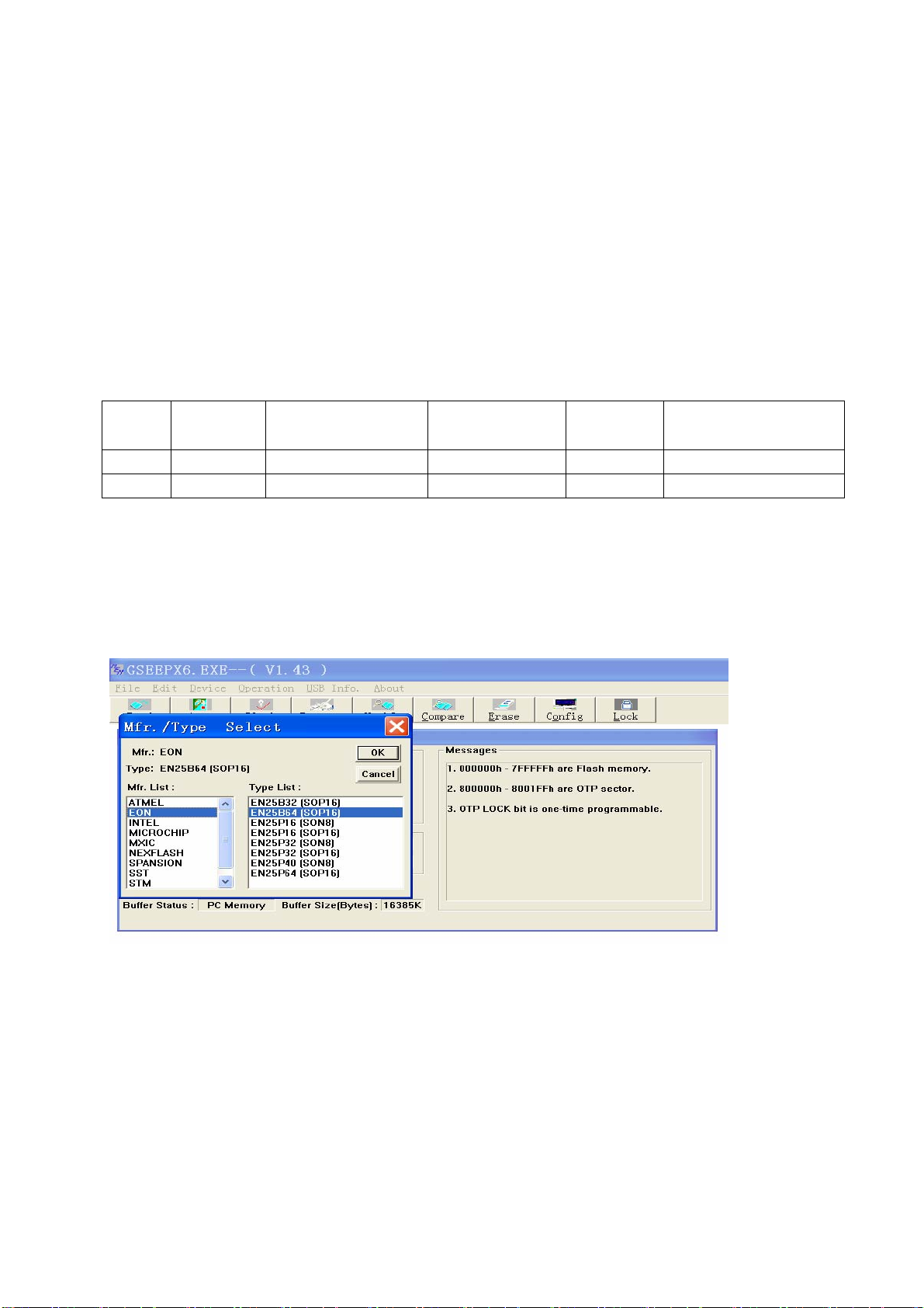
8.1 Execute ALL-100 upgrading file GSEEP.EXE;
8.2 Click menu Device, select FLASH model EN25Q32B shown as Fig. 3;
Note: real FLASH model depends on the real material, models shown by Fig. 3 are just for illustration.
Fig. 3 Device model selection interface
8.3 Click toolbar AUTO, enter into interface AUTO, make sure to tick off option Config when
upgrading Flash. Please refer to Fig. 4.
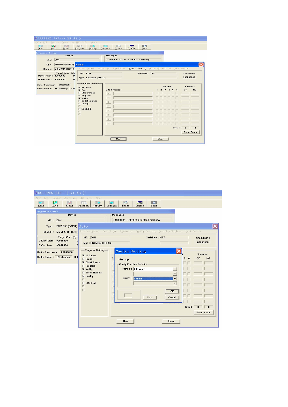
Fig. 4 AUTO upgrading interface
8.4 Click option Config Setting in AUTO interface, set option Protect as All Protect, and set
option SRWD as Enable, then click ‘OK’ to complete write-protect setup. Make sure the above both
options are reset when executing ALL-100 upgrading software again after exiting it. If there is no
option SRWD, please upgrade ALL-100 upgrading software. Please refer to Fig. 5.
Fig. 5 Config Setting interface
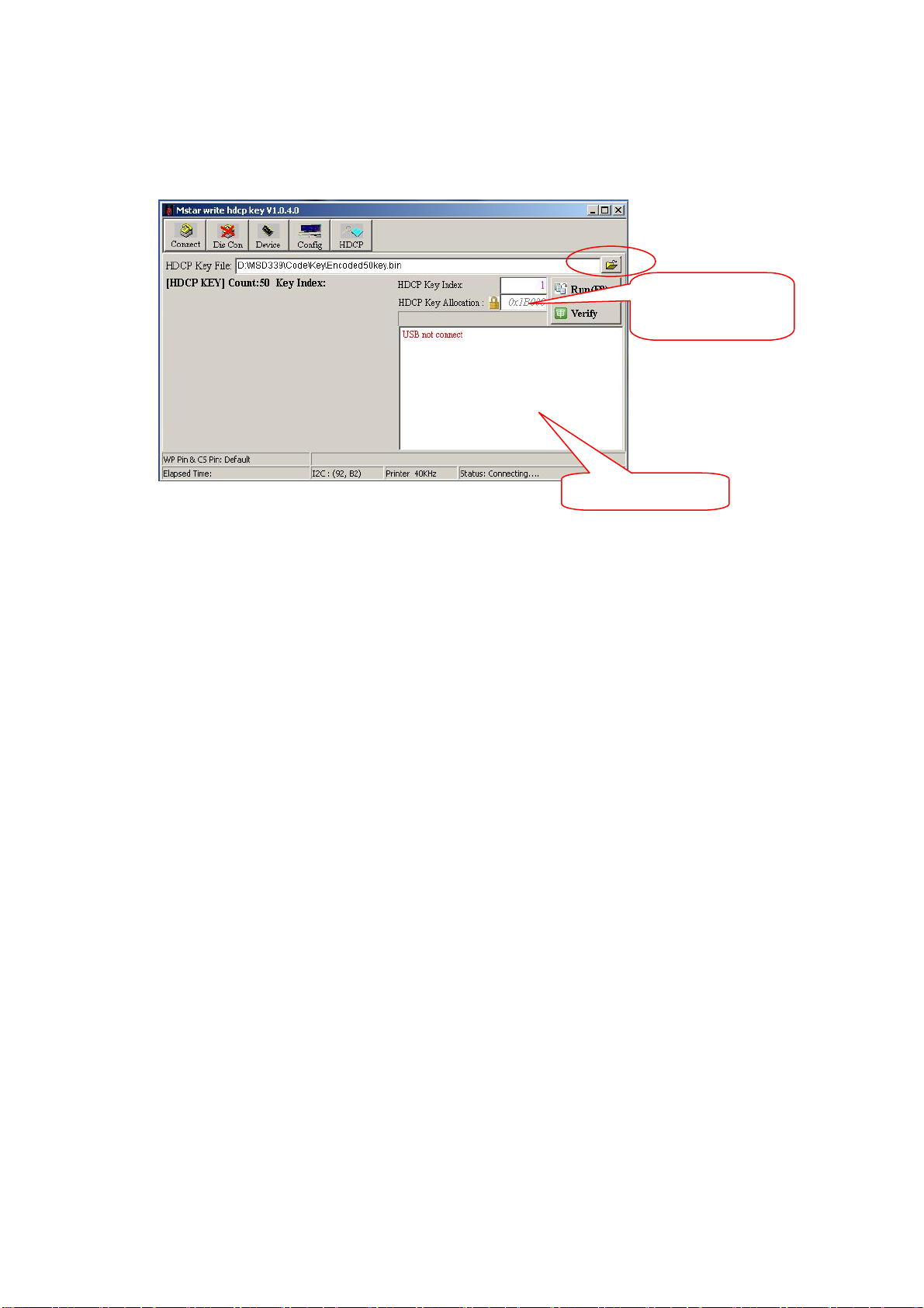
9 HDCP KEY upgrading methods
9.1 Connect to upgrading device;
9.2 Execute file ISP_ToolV1.04.exe which interface is shown as Fig. 6;
Location address:
0x3B0000
Fig. 6 ISP tool
9.3 Click button “Open” to load encrypted KEY file;
9.4 Click button “Run” to begin KEY upgrading. upgrading information will display in the information
frame after upgrading completed.
10 Software upgrading methods
10.1 Software upgrading methods from USB port (it is advise to use the method preferentially)
a) Copy file offered by RD department to the root directory of U disk. Note that the file name must
be MERGE.bin and be kept in the root directory of U disk.
b) Insert U disk to USB port, switch to non-USB channel (such as TV, AV channel, etc.), enter
into factory menu, choose “software upgrading USB”, then click “OK” to begin upgrading;
c) Click “Confirm upgrading” with left button when upgrading confirmation menu displays. Note
that U disk must not be pulled out or the unit must not be cut off during the upgrading process.
10.2 ISP(connected by VGA)upgrading method
a) Connect the unit and PC with upgrading connected board and VGA cable.
Information frame
b) Open upgrading tool ISP_Tool(V4.5.0.5), select label Device to make configuration within red
frame shown as Fig. 7;
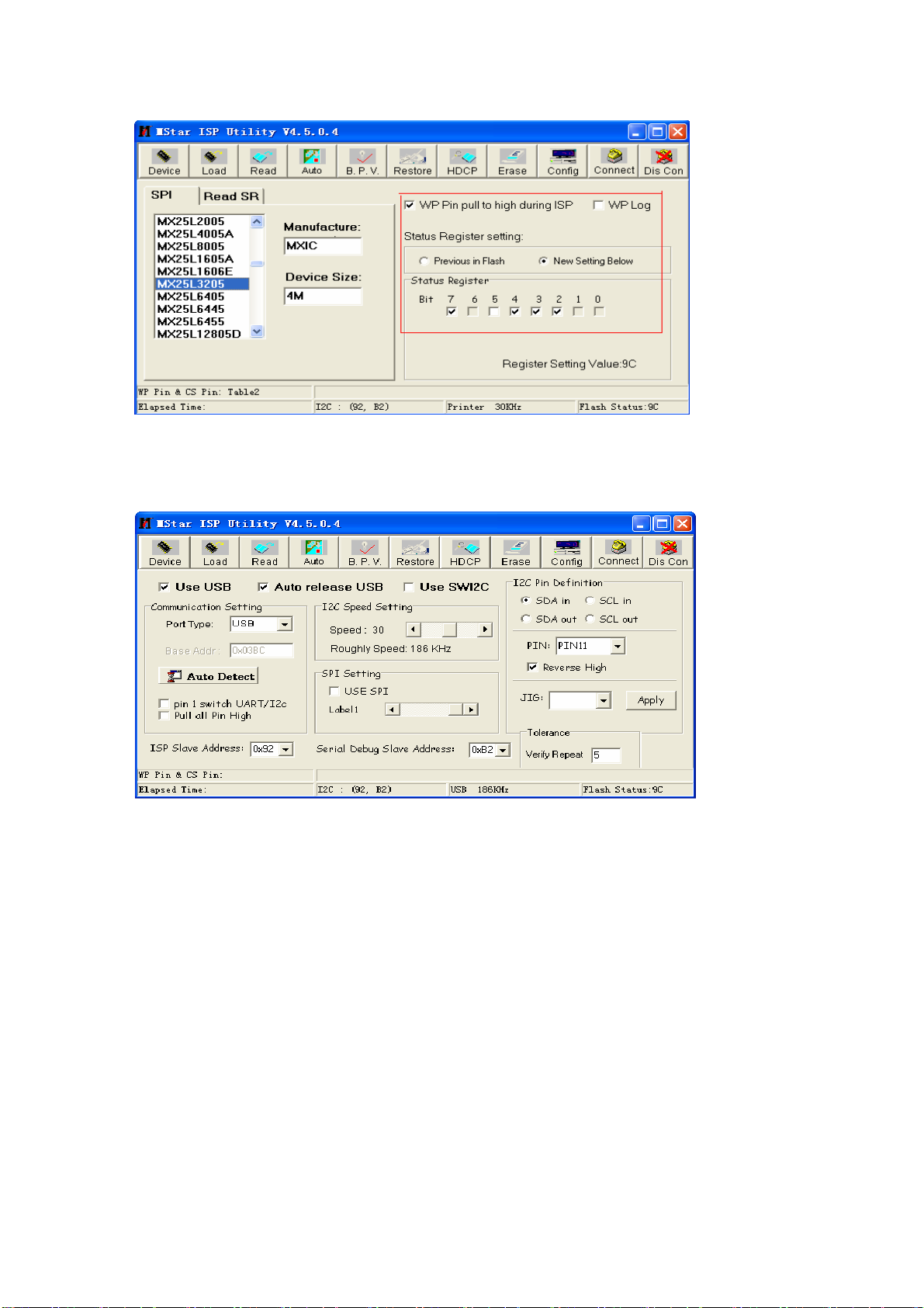
Fig. 7 Device configuration dialog
c) Select label Config to make configuration shown as Fig. 8;
Fig. 8 Config configuration dialog
Note: I2C speed is set as about 60% commonly and should not be set too fast. If it is not easy to
connect successfully, please set I2C speed slower.
d) Select label Read, open bin file whose file path can display completely in the label Auto,
e) Select label Auto, select items Read File, Erase Device (sub-item File Area of Erase Device
had better be selected), Program and Exit ISP, then click button “Connect”, a dialog shown as Fig. 9
will display if connection is successful, in which device type identified by the system automatically will
display and option “Flash_0” in the static frame “SpiFlash_X” will be ticked off. If device type or
“Flash_0” is not identified correctly, the connection is failed, then ISP tool will repeat identification
automatically until device type and “Flash_0” are identified correctly, if not, please check hardware
connection.
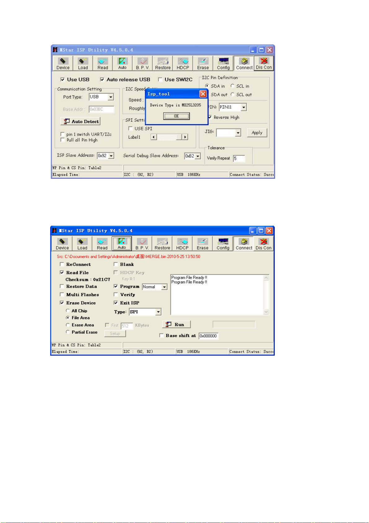
Fig. 9 Successful connect interface
f) Click button “Run” to begin software upgrading after successful connection . Please refer to
Fig. 10;
Fig. 10 Software upgrading interface
g) Successful software upgrading interface is shown as Fig. 11;
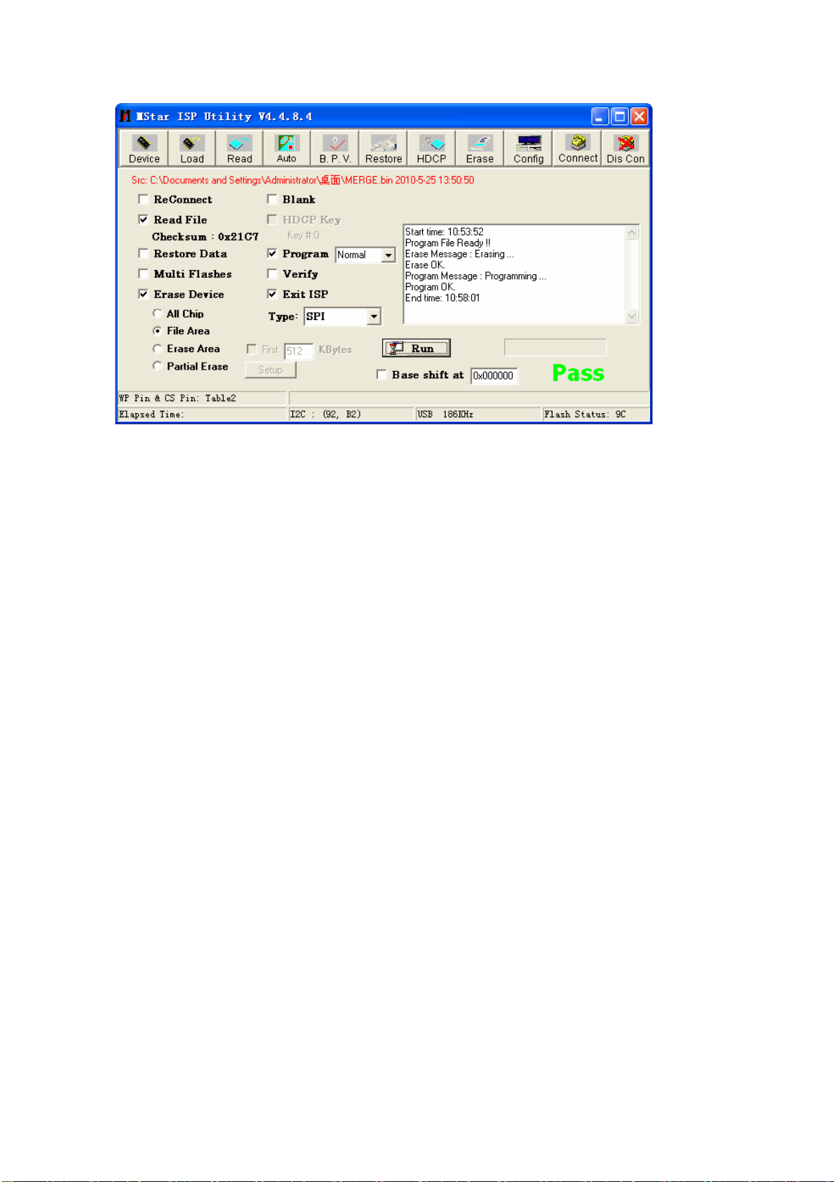
Fig. 11 Successful software upgrading interface
10.3 Software upgrading method from USB port (it is advised to use the method if the picture could
not display because of wrong panel parameters)
a) Copy file offered by RD department to the root directory of U disk. Note that the file name must
be MERGE.bin and kept in the root directory of U disk.
b) Insert U disk to USB port, keep pressing any key on the key board of the unit except key
“Standby” or “Input”, connect to power supply, switch on power switch of the unit, then IR indicator
light begins twinkling to show the unit is in the process of upgrading, unloose the key you press, the
unit will reset automatically after upgrading process completed.
Note that U disk must not be pulled out or the unit must not be cut off during the upgrading
process.
 Loading...