

Page 1
FILE NO.
SERVICE MANUAL
LED-LCD iDTV
LCE-32R40HDW
PRODUCT CODE No.
PRODUCT CODE No.
1 682 350 01: PAL-I
NTSC(AV)
REFERENCE No.:SM0915130
Page 2

CONTENTS
Safety precautions………………………………………………………………………..…
Alignment instructions …………………………….…….…………………………………
Method of software upgrading instructions………………………………………………..
Working principle analysis of the unit……………………………….………….………….
Block diagram…………………………………..………………………………….…………
IC block diagram and instruction…………………………………………………………..
Wiring diagram …………………………………………………………………………….
Troubleshooting guide ………………………………………………………………..……
Schematic diagram…………………………………………………………………………
APPENDIX-A: Main assembly list
APPENDIX-B: Exploded View
Assemble & Disassemble the Pedestal Base
Wall mounting instructions
3
5
14
18
20
21
30
31
34
Page 3

Attention: This service manual is only for service personnel to take reference with. Before
servicing please read the following points carefully.
Safety precautions
1. Instructions
Be sure to switch off the power supply before replacing or welding any components or
inserting/plugging in connection wire Anti static measures to be taken (throughout the entire
production process!):
a) Do not touch here and there by hand at will;
b) Be sure to use anti static electric iron;
c) It’s a must for the welder to wear anti static gloves.
Please refer to the detailed list before replacing components that have special safety requirements.
Do not change the specs and type at will.
Points for attention in servicing of LCD
2.
2.1 Screens are different from one model to another and therefore not interchangeable. Be sure to
use the screen of the original model for replacement.
2.2 The operation voltage of LCD screen is 700-825V. Be sure to take proper measures in protecting
yourself and the machine when testing the system in the course of normal operation or right after the
power is switched off. Please do not touch the circuit or the metal part of the module that is in
operation mode. Relevant operation is possible only one minute after the power is switched off.
2.3 Do not use any adapter that is not identical with the TV set. Otherwise it will cause fire or damage
to the set.
2.4 Never operate the set or do any installation work in bad environment such as wet bathroom,
laundry, kitchen, or nearby fire source, heating equipment and devices or exposure to sunlight etc.
Otherwise bad effect will result.
2.5 If any foreign substance such as water, liquid, metal slices or other matters happens to fall into
the module, be sure to cut the power off immediately and do not move anything on the module lest it
should cause fire or electric shock due to contact with the high voltage or short circuit.
2.6 Should there be smoke, abnormal smell or sound from the module, please shut the power off at
once. Likewise, if the screen is not working after the power is on or in the course of operation, the
power must be cut off immediately and no more operation is allowed under the same condition.
2.7 Do not pull out or plug in the connection wire when the module is in operation or just after the
power is off because in this case relatively high voltage still remains in the capacitor of the driving
circuit. Please wait at least one minute before the pulling out or plugging in the connection wire.
2.8 When operating or installing LCD please don’t subject the LCD components to bending, twisting
or extrusion, collision lest mishap should result.
2.9 As most of the circuitry in LCD TV set is composed of CMOS integrated circuits, it’s necessary to
pay attention to anti statics. Before servicing LCD TV make sure to take anti static measure and
ensure full grounding for all the parts that have to be grounded.
2.10 There are lots of connection wires between parts behind the LCD screen. When servicing or
moving the set please take care not to touch or scratch them. Once they are damaged the screen
would be unable to work and no way to get it repaired.
Page 4
If the connection wires, connections or components fixed by the thermotropic glue need to disengage
when service, please soak the thermotropic glue into the alcohol and then pull them out in case of
dagmage.
2.11 Special care must be taken in transporting or handling it. Exquisite shock vibration may lead to
breakage of screen glass or damage to driving circuit. Therefore it must be packed in a strong case
before the transportation or handling.
2.12 For the storage make sure to put it in a place where the environment can be controlled so as to
prevent the temperature and humidity from exceeding the limits as specified in the manual. For
prolonged storage, it is necessary to house it in an anti-moisture bag and put them altogether in one
place. The ambient conditions are tabulated as follows:
o
Temperature Scope for operation 5 ~ +35
C
Scope for storage -20 ~ +45 oC
Humidity Scope for operation 20% ~ 80%
Scope for storage 10% ~ 90%
2.13 Display of a fixed picture for a long time may result in appearance of picture residue on the
screen, as commonly called “ghost shadow”. The extent of the residual picture varies with the maker
of LCD screen. This phenomenon doesn’t represent failure. This “ghost shadow” may remain in the
picture for a period of time (several minutes). But when operating it please avoid displaying still
picture in high brightness for a long time.
3. Points for attention during installation
3.1 The front panel of LCD screen is of glass. When installing it please make sure to put it in place.
3.2 For service or installation it’s necessary to use specified screw lest it should damage the screen.
3.3 Be sure to take anti dust measures. Any foreign subst ance that happens to fall down between the
screen and the glass will affect the receiving and viewing effect
3.4 When dismantling or mounting the protective partition plate that is used for anti vibration and
insulation please take care to keep it in intactness so as to avoid hidden trouble.
3.5 Be sure to protect the cabinet from damage or scratch during service, dismantling or mounting.
Page 5
Alignment instructions
Test equipment
VG-848 (YPbPr, VGA signal generator)
VG-849 (HDMI signal generator)
CA210 (white balance equipment)
Alignment flow
1
1.1 Voltage of power supply test
According to the wiring diagram specified by product specification, connect power board
assembly, main board assembly/digital board assembly, IR assembly/Light sensor assembly,
key board assembly and backlight board assembly correctly; then power on and press key
to turn on the unit.
a) Test each pin voltage of 13-pin power socket X601 in turn listed as Table 1.
Table 1 Voltage of 13-pin power socket each pin of LED
Pin 1 2 3 4、5 6、7 8 9 10 11 12 13
Voltage
b) Test each pin voltage of 5-pin power socket X606 in turn listed as Table 2. (for 26’’ a nd above)
≥2.5V ≥2.0V 0 12 V±5% 0 N.C. 5 V±5% 0 5 V±5% 0 ≥2.5V
Table 2 Voltage of 5-pin power socket each pin
Pin 1, 2 3, 4, 5
Voltage
24V±5% 0
Page 6
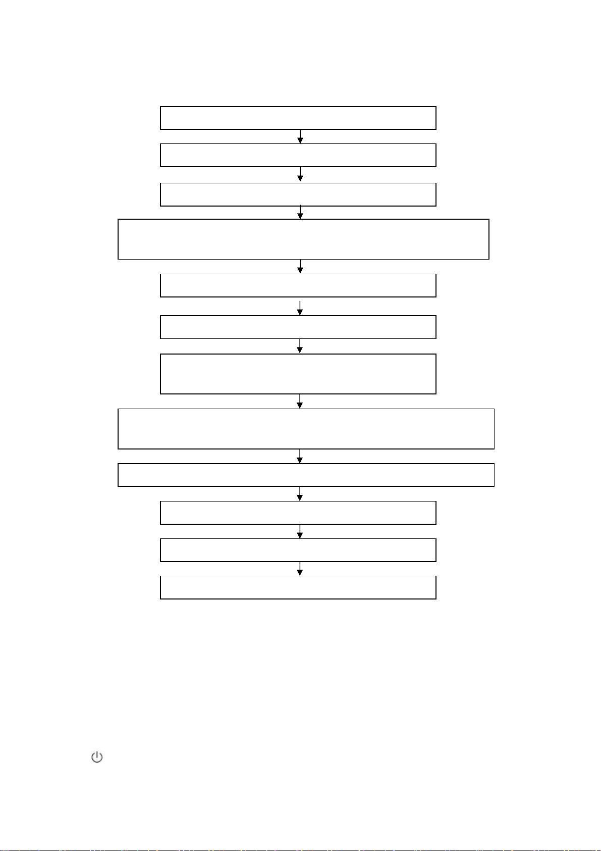
1.2 Adjustment flow chart shown as Fig.1
Connect to central signal source, check if TV functions are normal –omitted channel,
analog parameters control, etc; check if output of earphone and speaker is normal.
Input HDMI signal,check if the display is normal; check if every function is normal –analog
Connect to USB device, check if the display is normal; check if every function is normal.
Check if EDID, HDCP KEY and FLASH have been burned.
Combination adjustment for general assembly
White balance adjustment
Input AV signal,check if every function is normal.
Input YPbPr signal,check if every function is normal.
Input RGB signal,check if the display is normal; check if every
function is normal –analog parameter control, horizontal/vertical
parameter control, horizontal/vertical center, etc.
Check if other functions are normal – LCN, OTA, etc.
Check accessaries and packing
Fig.1 Adjustment flow chart
Ex-factory setup
2 Alignment instruction
2.1 Unit adjustment
2.1.1 According to the wiring diagram specified by product specification, connect power board
assembly, main board assembly/digital board assembly, IR assembly/Light sensor assembly,
key board assembly and backlight board assembly correctly; then power on and press key
to turn on the unit. Check if the display is normal.
Page 7

2.1.2 Using method of factory menu
a) First press key “SOURCE”,then press number key “2、5、8、0” in turn to enter into initial
factory menu;
b) Press keys “▲” and “▼” can move cursor to each page of initial factory menu, then press
key “OK” to enter into adjustment menu of each page;
c) Press keys “▲” and “▼” can move cursor upwards and downwards within one adjustment
page;
d) Move cursor to one adjustment item, then press keys “◄” and “►” can adjust it;
e) Press key “MENU” can exit adjustment menu of one page to its superior factory menu;
f) Press key “EXIT” can exit factory menu at any time;
g) Press key “OK” can enter into inferior factory menu;
h) Factory menu item “ADC Calibrate” is used to correct ADC of YPBPR and RGB channel
i) Factory menu item “W/B ADJUST” is used to adjust white balance;
j) Factory menu item “POWER MODE” is used to set power-on mode:
“Standby” means the set will be in Standby state after power-on;
“ Memory ” means the set will in the last power-off state after power-on ;
“ForceOn” means the set will be working automatically after power-on , the mode is also
used for factory-machine-aging; default setting should be “Standby” mode unless specified
by customer requirement;
k) Factory menu item “ISP MODE” is used to upgraded unit software from VGA port when the
item is set as “ON” and the set is connected to ISP adjustment equipment; DDC function of
VGA port will be recovered when the item is set as “OFF”; the value of the item can not be
kept in the memory, that is to say the item is reset as “OFF” after power-on again;
l) Factory menu item “RESET ALL” is used to reset factory menu data and user menu data;
execute the item then the set will be started up again and the startup guided picture will be
displayed also;
m) Factory menu item “FACTORY CHANNEL PRESET” is used to preset factory programs
data; it is necessary to connect to central signal source for DTV searching programs. Now
digital frequency of central signal CH40(626 MHz) is distributed to HK DTMB programs.
Primary preset programs would not be modified along with the changing of central signals,
so please select item “DTV Manual Tuning” in menu Channel to manual search digital
programs, the process will spend about 15s;
n) Factory menu item “CUSTOM CHANNEL PRESET” : first delete all DTV/ATV programs for
factory adjustment, then preset DTV/ATV channel data according to customer order
requirements; please execute the item to clear out all programs for factory adjustment
before leaving factory;
o) Factory menu item “MST ADJUST”: Default is “OFF”. Engineering sample with RS-232
functions matches the design specifications when the item is set as “OFF”; It’s convenient to
adjust with equipment when it’s set as “ON”, the value of the item can not be kept in the
memory, that is to say the item is reset as “OFF” after power-on again;
p) Factory menu item “BACKLIGHT” is used to adjust backlight brightness, test voltage of
13-pin power socket and adjust the item to meet the requirement of maximum PWM
voltage in panel specification; the software have been preset according to model need not
be adjusted;
Page 8

q) Factory menu item “SSC ADJUST” is used to adjust expended functions of spectrum, the
software have been preset according to model need not be adjusted;
r) Factory menu item “Others”-> “Audio curve” is used to adjust volume curve; the software
have been preset according to model need not be adjusted unless special customer
requirements;
s) Factory menu item “Software upgrade” is used to upgrade USB, after select confirm the
software will search AP.bin stored in USB device to upgrade at any channel ; If the software
has been upgraded or EEPROM has data, please select and execute operation “RESET
ALL” before adjustment for the first time.
2.1.3 ADC correction of Component channel YPbPr
a) Switch to Component channel YPbPr;
b) Press key “SOURCE”,then press number keys “2、5、8、0” to enter into initial factory menu;
c) Move cursor to item “ADC Calibrate” and press key “OK” to enter into interior factory menu;
d) Input YPbPr Component signal (VG-848 Timing:969(PAL),Pattern:918 100% color bar),
move cursor to item “MODE”,press keys “▲” and “▼” to select item “YPbPr(SD)”, then
move cursor to item “AUTO ADC” and press key “OK” to begin adjustment automatically
until a prompt “success” for adjustment completion is displayed;
e) Input YPbPr Component signal (VG-848 Timing:972(1080i),Pattern:918 100% color bar),
move cursor to item “MODE”,press keys “▲” and “▼” to select item “YPbPr(HD)”, then
move cursor to item “AUTO ADC” and press key “OK” to begin adjustment automatically
until a prompt “success” for adjustment completion is displayed.
2.1.4 ADC correction of RGB channel
a) Switch to RGB channel (D-SUB channel);
b) Press key “SOURCE”, then press number keys “2、5、8、0
c) Move cursor to item “ADC Calibrate” and press key “OK” to enter into interior factory menu;
d) Input RGB signal (VG-848 Timing:856(1024×768/60 Hz),Pattern:920 8 step Gray), move
cursor to item “MODE”,press keys “▲” and “▼” to select item “RGB”, then move cursor to
item “AUTO ADC” and press key “OK” to begin adjustment automatically until a prompt
“success” for adjustment completion is displayed.
2.2 White balance adjustment
Unless specified by customer, default COOL color temperature is 12000K, chromaticity
coordinates is (272、278); default Standard color temperature is 9300K, chrom aticity coordinates
is(285、293); default Warm color temperature is 6500K, chromaticity coordinates is (313、
329).
2.3 White balance adjustment processes
The set should be working above 30 minutes before white balance adjustment for it would be in
a stabler state. Use white balance apparatus CA-210 and switch to its BBY channel.
1) Auto white balance adjustment;
2) Manual white balance adjustment if auto adjustment is failed;
a) Switch to HDMI channel
b) Press key “SOURCE”, then press number keys “2、5、8、0” in turn to enter into initial factory
menu;
c) Move to item “W/B ADJUST” and press key “OK” to enter into interior factory menu;
d) Input HDMI signal (VG-848 Timing: 856(1024×768/60 Hz),Pattern:921 16 step Gray),
” to enter into initial factory menu;
Page 9

move cursor to item “MODE”, press keys “▲” and “▼” to select item “HDMI”, then move
cursor to item “TEMPERTURE”, press keys “▲” and “▼” to select item “Standard”;
e) Fix item “G GAIN”, adjust item “R GAIN、B GAIN” to set chromaticity coordinates of the 13
step is (285、293);
f) Fix item “G OFFSET”, adjust item “R OFFSET、B OFFSET” to set chromaticity coordinates
th
of the 4
g) Fix item “G OFFSET”, adjust item “R OFFSET、B OFFSET” to set chromaticity coordinates
of the 4
h) Then move cursor to item “COPY ALL” to copy white balance data to the other channels;
i) Check if color temperature of COOL and WARM meet the requirements as below:
COOL: allowable error of bright step is (X±5, Y±15), allowable error of dark step is
WARM: allowable error of bright and dark step are both (X±10,Y±10);
otherwise adjust items “R_GAIN /B_GAIN/R_OFF/B_OFF” to meet the requirements and
then save data;
j) Check if the white balance of the other channels meet the requirements, if not, adjust the data
and save them separately;
k) Check if the picture of every channel is normal after adjustment;
l) Adjustment rules for reference as below:
adjust B gun: adjust B gun value downwards , then coordinates of X、Y will rise;
adjust B gun value upwards , then coordinates of X、Y will descent;
adjust R gun : effect the coordinate of X and effect the value of Lv a little:
adjust R gun value upwards , then coordinate of X will rise;
adjust R gun value downwards , then coordinate of X will descent;
adjust G gun: effect the coordinate of Y and effect the value of Lv a lot:
adjust G gun value upwards , then coordinate of Y will rise;
adjust G gun value downwards , then coordinate of Y will descent.
step is (285、293)
th
step is (285、293);
(X±8,Y±30);
th
3 Performance check
3.1 DTV/ATV functions
Connect RF port to central signal source, first enter into menu “CHANNEL”, then search
programs automatically, check if there is any omitted program of ATV、DTV, check if the output of
speakers is normal, check if the picture is normal.
3.2 Composite AV ports
Input composite AV signal, check if the picture and the sound are normal under the circustances
of power-on, switching channel, switching signal format, etc.。
3.3 Component YPbPr port
Input YPbPr Component signal from signal generator VG-848 with the formats as Table 3
respectively, check if the display and the sound are normal under the circumstances of power-on/off,
switching channel, switching signal format, etc.
Page 10
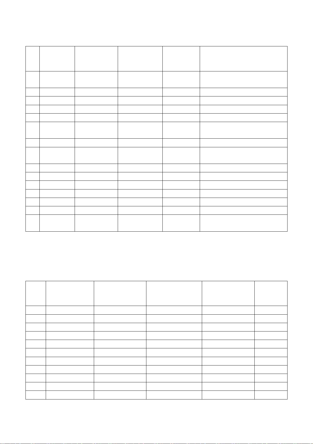
Table 3 Component receiving signal formats
No
Definition
.
1 720×480 15.734/15.75 59.94/60 13.5/13.514
2 720×576 15.625 50 13.5 576i (PAL, PAL-N, SECAM)
3 720×480 31.469/31.5 59.94/60 27/27.027 480p
4 720×576 31.25 50 27 576p
5 1280×720 37.5 50 74.25 720p (50p)
6 1280×720 44.955/45 59.94/60
7 1920×1080 28.125 50 74.25 1080i (50i)
8 1920×1080 33.75 59.94/60
9 1920×1080 26.973 23.976 74.176 1080p (23.97p)
10 1920×1080 27 24 74.25 1080p (24p)
11 1920×1080 28.125 25 74.25 1080p (25p)
12 1920×1080 33.716 29.97 74.176 1080p (29.97p)
13 1920×1080 33.75 30 74.25 1080p (30p)
14 1920×1080 56.25 50 148.5 1080p (50p)
15 1920×1080 67.432/67.5 59.94/60
3.4 R,G,B port
Input RGB D-SUB signal from signal generator VG-848 with the formats as Table 4 respectively,
check if the display and the sound are normal under the circumstances of power-on/off, switching
channel, switching signal format, etc. if there is any deviation of line or field, enter into main menu
and select items “Picture->Screen->Auto Adjusting” in turn to correct them automatically.
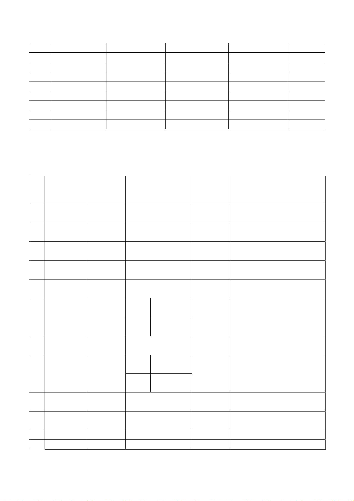
Table 4 R,G, B receiving signal formats
No. Definition
1 640×480 31.469 59.94 25.175 IBM
2 720×400 31.469 70.086 28.322 IBM
3 640×480 37.861 72.809 31.5 VESA
4 640×480 37.5 75 31.5 VESA
5 800×600 35.156 56.25 36 VESA
6 800×600 37.879 60.317 40 VESA
7 800×600 48.077 72.188 50 VESA
8 800×600 46.875 75 49.5 VESA
9 1024×768 48.363 60.004 65 VESA
10 1024×768 56.476 70.069 75 VESA
11 1024×768 60.023 75.029 78.75 VESA
Horizontal
frequency
(kHz)
Horizontal
frequency
(kHz)
Vertical
frequenvy
(Hz)
Vertical frequenvy
Dot-pulse
frequency
(MHz)
74.176/74.2
5
74.176/74.2
5
148.35/148.
5
(Hz)
Remark
480i (NTSC,
NTSC4.43,PAL60,PAL-M)
720p (59.94p/60p)
1080i (59.94i/60i)
1080p (59.94p/60p)
Dot-pulse
frequency
(MHz)
Remark
Page 11
12 1152×864 67.5 75 108 VESA
13 1280×960 60 60 108 VESA
14 1280×1024 63.98 60.02 108 VESA
15 1280×1024 80 75 135 SXGA
16 1360×768 47.7 60 85.5 WXGA
17 1440×900 55.9 60 106.5 WXGA+
18 1400×1050 65.22 60 122.61 SXGA+
19 1680×1050 65.3 60 146.25 WSXGA+
20 1920×1080 67.5 60 148.5
3.5 HDMI port
Input HDMI signal from signal generator VG-849 with the formats as Tab le 5, check if the display
and the sound(32 KHz、44.1 KHz、48 KHz)are normal under the circumstances of power-on/off,
switching channel, switching signal format, etc.
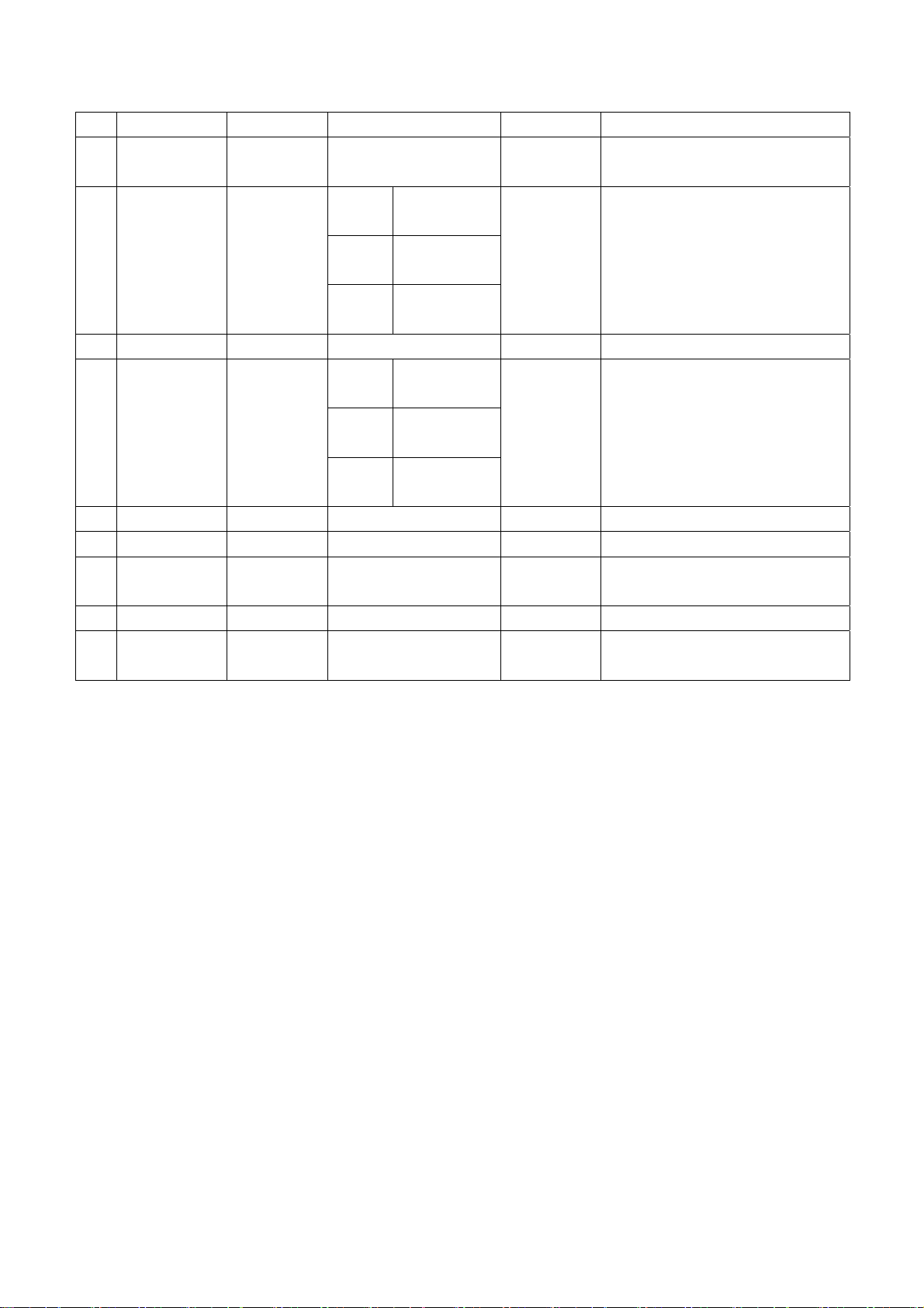
Table 5 HDMI receiving signal formats
No
Definition
.
1 640×480
2 720×480
3 1280×720 44.955/45 59.94/60
4 1920×1080
720(1440)
5
×480
720(1440)
6
×240
7 (2880)×480
8 (2880)×240
9 1440×480
10 1920×1080
11 720×576 31.25 50 27 720×576p@50 Hz,4:3/16:9
12 1280×720 37.5 50 74.25 1280×720p@50 Hz
Horizontal
frequency
(kHz)
31.469/31.
5
31.469/31.
5
33.716/33.
75
15.734/15.
75
15.734/15.
75
15.734/15.
75
15.734/15.
75
31.469/31.
5
67.432/67.
5
Vertical frequenvy
(Hz)
59.94/60
59.94/60 27/27.027
59.94/60
59.94/60 27/27.027
Mode 1 59.826/59.8
86
Mode 2 60.054/60.1
15
59.94/60 54/54.054
Mode 1 59.826/59.8
86
Mode 2 60.054/60.1
15
59.94/60 54/54.054
59.94/60
Dot-pulse
frequency
(MHz)
25.175/25.
2
74.176/74.
25
74.176/74.
25
27/27.027
54/54.054
148.352/1
48.5
Remark
640×480p@59.94/60 Hz
720×480p@59.94/60
Hz,4:3/16:9
1280×720p@59.94/60 Hz
1920×1080i@59.94/60 Hz
720(1440)×480i@59.94/60
Hz,4:3/16:9
720(1440)×240p@59.94/60
Hz,4:3/16:9
(2880)×480i@59.94/60
Hz,4:3/16:9
(2880)×240p@59.94/60
Hz,4:3/16:9
1440×480p@59.94/60
Hz,4:3/16:9
1920×1080p@59.94/60 Hz
Page 12
13 1920×1080 28.125 50 74.25 1920×1080i@50 Hz
720(1440)
14
×576
720(1440)
15
×288
16 (2880)×576 15.625 50 54 (2880)×576i@50 Hz,4:3/16:9
17 (2880)×288 15.625
18 1440×576 31.25 50 54 1440×576p@50 Hz,4:3/16:9
19 1920×1080 56.25 50 148.5 1920×1080p@50 Hz
20 1920×1080 26.973/27 23.97/24
21 1920×1080 28.125 25 74.25 1920×1080p@25 Hz
22 1920×1080
3.6 USB port
3.6.1 Media playing function
Insert USB memory with picture, audio and video files, check if each function, such as display,
sound, etc., is normal;
3.6.2 PVR function
Insert USB memory which has been formatted and saved recording programs, press key “Rec.
List” to select and play program, check if each function, such as display, sound, etc., is normal;
3.7 Music channel port
Input audio signal, check if sound is normal;
3.8 Other functions check
a) Check if composite AV output port, digital audio port, earphone output jack, etc., are normal;
b) Check if function of logic channel number (LCN) and (OTA) is normal;
3.9 Network channel port
Please refer instruction to the following step 8 in detail, check if each function, such as display,
sound, etc., is normal;
15.625 50 27
15.625
33.716/33.
75
Mode
1
Mode
2
Mode
3
Mode
1
Mode
2
Mode
3
29.97/30
49.761
49.92
50.08
49.761
49.92
50.08
27
54 (2880)×288p@50 Hz,4:3/16:9
74.176/74.
25
74.176/74.
25
720(1440)×576i@50
Hz,4:3/16:9
720(1440)×288p@50
Hz,4:3/16:9
1920×1080p@23.97/24 Hz
1920×1080p@29.97/30 Hz
4 User menu setup before leaving factory
Enter into page “LOCK” of user menu and iput the initial password “0000 “, select submenu item
“Restore Factory Default” then press “OK“ to preset items before leaving factory as below::
Page 13

a) Clear out all programs information;
b) Clear out information of block program and favorite channels;
c) Default setup of user analog data
d) Set Menu Language as “English;”
e) Set Power on MODE as “Standby”
Page 14

Method of software upgrading instructions
Instruction of factory software burning as Table 6
Table 6 Instruction of factory software burning
Instructi
on of
software
function
size
Loc.
No.
Part No. Part type
Burne
d
before
SMT
Burning method
NA05 52712805
01
Belo
26”
26”
and
abov
Note 1: Write-protect setup method
NA02 52724040
w
NA07 52724020
NB04 52724020
N103 52712805
N105 52724040
N40
2
N40
e
5
N41
7
N206 52724020
Enter into interface of burning program ALL-100, select item “Config”, press item “config
Setting”, set item “Protect” as “All Protect”. Be sure to select item “Config” before burning
software, and write-protect must be re-set after burning program ALL-100 startup every time.
02
02
02
01
02
52724020
02
02
MX25L12805
DMI-20G
AT24C04
AT24C02
AT24C02
MX25L12805
DMI-20G
AT24C04
AT24C02
AT24C02
Main
program
HDCP
KEY
HDMI
EDID
VGA
EDID
Main
program
HDCP
KEY
HDMI
EDID
VGA
EDID
Yes
Yes
Yes
Yes
Yes
Yes
Yes
Yes
Burned with program ALL100,
write-protect setup, refer to Note
1 in detail
Burned with program ALL100
Burned with program ALL100
Burned with program ALL100
Burned with program ALL100,
write-protect setup, refer to Note
1 in detail
Burned with program ALL100
Burned with program ALL100
Burned with program ALL100
Page 15
Note 2: Burning and upgrading software method with burning tool ISP:
a) Main board upgrading: connect 4-core line of burning tool ISP to Debug port of main board
(location No. XM04 for below 26” and No. X505 for 26” and above);
Unit upgrading: connect both VGA ports between burning tool ISP and main board, then
enter into factory menu and set item “ISP Mode” as “ON”;
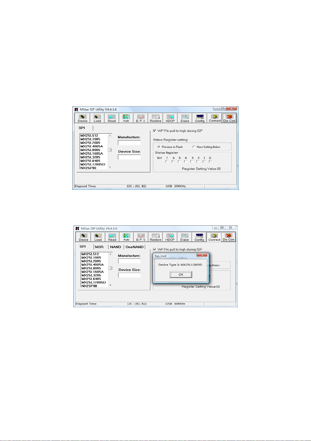
b) Use on-line burning tool of Mstar, enter into menu “Device”, select item “WP Pin pull to high
during ISP” as Fig. 2, make sure hardware write-protect of Flash has been removed to
ensure the normal erasing process;
Fig. 2 Write-protect setup
c) Select menu “Connect”, a dialog “Device Type is MX25L12805D” will be displayed as Fig. 3
to show succeeding in connecting. If failing to connecting, select the first menu “Device” and
manual select item “MX25L1280D”, then press key “Connect”;
Fig. 3 Successful connection
d) Press key “Read”,select burning file (for example MERGE.bin) as Fig. 4.
Page 16

Fig. 4 Burning file
e) Select menu “Auto”, then select items “All chip”, “program” and other switches as Fig. 5;
Fig. 5 Switches
f) Press key “Run” as Fig. 4 to begin burning software, there are two steps for the process:
Erase and Program, normal burning processes are as follows:
1)The first course “Erasing…” will be lasting for a moment, otherwise skipping over means
unsuccessful erasing; please confirm process (2) and then burn software again;
2)The following course “Programming…”;
3)A prompt “Pass” is displayed at last.
g) A prompt “Pass” will be displayed beside the key “Run” for successful burning as Fig. 6;
Fig. 6 Successful burning
Page 17

h) Need not exit from ISP burning interface and only repeat the process c)and e)to go on
burning software for other sets;
Note 3: On-line burning and upgrading method from a USB port:
a) Be sure to format a USB disk as FAT32;
b) Copy program file to the USB disk with the name “AP.bin”;
c) Power on, press key “SOURCE” and number keys “2, 5, 8, 0” in turn to enter into initial
factory menu at any channel;
d) Enter into factory menu item “software upgrade”, select “confirm” to search AP.bin stored
in USB disk automatically to upgrade the software; upgrade progress is below:
1) Reading USB disk,a prompt “ Searching USB” will display and an USB disk indicator light
is twinkling ;
2) Burning Flash, prompts “Updating! Please don’t power off!!!” and “upgrading schedule”
will display at the same time, after the burning process completed the set will re-start
automatically.
e) Start up the set again, enter into factory menu to confirm software version and time
parameters; then execute “RESET ALL” to complete the whole burning process;
f) Method of burning from USB could not be sure to be suitable for all kinds of USB disks, so
please try other USB disks if necessary.
Page 18

Working principle analysis of the unit
1、 PAL/SECAM signal flow
PAL/SECAM analog RF signal from antenna is inputted into TUNER FT2112 which is an
2
analog-digital-integrative model and controlled by main chip MSD209FG through I
signal is demodulated by the TUNER, then CVBS signal and audio difference IF signal SIF are
outputted.
TV CVBS signal is inputted into main chip MSD209FG directly to be processed by modules
“VIDEO DECODER, DEINTERLACE , VIDEO PROCESS and SCALER”, then LVDS signal is
outputted to drive LCD panel.
SIF audio signal is inputted into main chip MSD209FG directly and processed by modules of
demodulation, pre-amplification, acoustic effect processing and volume control, then the audio signal
are divided to two signals, one is inputted into earphone amplifiers BH3547F to be amplified, then is
outputted to earphone jack, the other is inputted into D class audio power amplifier TAS5711 to be
amplified, then is outputted to drive speakers.
2、 DTMB signal flow
DTMB signal from antenna is inputted into TUNER FT2130 to be lower frequency converted,
TUNER FT2130 is an analog-digital-integrative model and controlled by main chip MSD209FG
2
through I
demodulated and then be inputted into main chip MSD209FG with standard format of serial or
parallel transport stream for de-multiplexing and decoding.
MSD209FG and then output LVDS signal to drive display panel.
then dual-track (stereo) analog audio signal is outputted and processed by modules of
pre-amplifying, acoustic effect processing and volume control in MSD209FG, then the signal is
divided into two signals, one is sent into earphone amplifier BH3547F to be amplified, then outputted
to earphone jack directly, the other is inputted into class-D audio power amplifier TAS5711 to be
amplified and then outputted to drive speakers.
3、
“VIDEO DECODER, DEINTERLACE, VIDEO PROCESS and SCALER”, then LVDS signal is
outputted to drive LCD panel.
alternating-current coupling”, then inputted into main chip MSD209FG directly for acoustic effect
processing and volume control, now the signal is divided into two signals, one is inputted into
earphone amplifier BH3547F to be amplified, then outputted to earphone jack directly, the other is
inputted into class-D audio power amplifier TAS5711 to be amplified and then outputted to drive
speakers.
4、
of “A/D TRANSFORM, VIDEO DECODER, DEINTERLACE, VIDEO PROCESS and SCALER”, then
C bus, then different IF signal is outputted to demodulating chip LGS-8G80 to be
Video route: de-multiplex digital video signal is decoded and video processed by main chip
Audio route: de-multiplex digital audio signal is decoded and audio processed by MSD209FG,
AV input signal flow
AV video signal is inputted into main chip MSD209FG directly and processed by modules of
AV audio signal is processed by circuits of “voltage divided, impedance matching and
D-SUB/YPbPr signal flow
D-SUB, YPbPr video signal is inputted into main chip MSD209FG to be processed by modules
C bus, the RF
Page 19

LVDS signal is outputted to drive LCD panel.
D-SUB, YPbPr audio signal is processed by circuits of “voltage divided, impedance matching
and alternating-current coupling”, then inputted into main chip MSD209FG directly for acoustic effect
processing and volume control, now the signal is divided into two signals, one is inputted into
earphone amplifier BH3547F to be amplified, then outputted to earphone jack directly, the other is
inputted into class-D audio power amplifier TAS5711 to be amplified and then outputted to drive
speakers.
HDMI signal flow
5、
HDMI video signal inputted into main chip MSD209FG to be processed by modules of “VIDEO
DECODER, VIDEO PROCESS and SCALER”, then LVDS signal is outputted to drive LCD panel.
HDMI audio signal is inputted into main chip MSD209FG directly for sound processing,
pre-amplify, acoustic effect processing and volume control, now the signal is divided into two signals,
one is inputted into earphone amplifier BH3547F to be amplified, then outputted to earphone jack
directly, the other is inputted into class-D audio power amplifier TAS5711 to be amplified and then
outputted to drive speakers.
AV output signal flow
6、
The present video signal is outputted from MSD209FG after processed by video decoding
module and peripheral video amplifying circuits. Then the present audio signal is processed by
MSD209FG modules of pre-amplification, acoustic effect processing and volume control, then sent to
operational amplifier to be amplified and outputted.
SPDIF signal flow
7、
The present audio signal is outputted after processed by MSD209FG modules of acoustic effect
processing, volume control and digital audio decoding.
Page 20

Block Diagram
Page 21

IC BLOCK DIAGRAM
1、 MSD 209FG
GENERAL DESCRIPTION
The MSD209GL is a highly integrated controller IC for LCD/PDP DTV applications with resolutions
up to full-HD(1920 x 1080). It is configured with an integrated triple-ADC/PLL, a multi-standard TV
video and audio decoder, a motion adaptive video de-interlacer, a scaling engine, the MStarACE-3
color engine, an advanced 2D graphics engine, a transport processor, a high-definition (HD) MPEG
video decoder, a high-definition (HD) H.264 video decoder, a RealVideo decoder, a JPEG video
decoder, a MPEG-4 decoder, and a 24-bit DSP for MPEG audio decoding, a DVI/HDCP/HDMI
receiver, and a peripheral control unit providing a variety of HDTV control functions.
For digital TV application, the MSD209GL comprises an MPEG-2 transport processor with advanced
section filtering capability, an MPEG-2 (MP@HL profile) video decoder, a MPEG-4 decoder, a H.264
video decoder, and an audio DSP decoder for MPEG audio streams, MPEG layer I and II digital
audio decoder with analog audio outputs that are designed to support existing and future DVB-T
programs while handling conditional access. Furthermore,it is also possible to decode JPEG,
RealVideo streams, and MP3 formats from external sources such as USB interface.
For analog TV, the MSD209GL includes NTSC/PAL/SECAM multi-standard video decoder
comprising a 3D motion adaptive comb filter and time-based correction, and a NICAM/A2 audio
decoder to support worldwide television standards. The MSD209GL is also configured with a VBI
processor to decode digital information such as Close Caption/V-chip/teletext/WSS/CGMS-A/VPS.
In addition, the MStar advanced LCD TV processor enhances video quality, motion adaptive
de-interlacer, picture quality adjustment units, and MStarACE-3 color engine.
With USB 2.0 host controllers, UART, IR, SPI, I2C, and PWM, the MSD209GL fulfills all
requirements in advanced DTV sets. To reduce system costs, the MSD209GL also integrates
intelligent power management control capability for green-mode requirements and spread-spectrum
support for EMI management.
MSD209GL Features:
Twin-turbo 8051 Micro-controller
z Twin-turbo 8051 MCU
z Interrupt controller
z Supports ISP
z Two full duplex UARTs
z DMA engine to speed up large data movement
Transport Stream De-multiplexer
z One external TS input and one internal TS data path
z Supports serial TS interface, with or without sync signal
z Maximum TS data rate is 104 Mb/sec
z 32 general purpose PID filters and section filters for each transport stream de-multiplexer
z One video PES and one audio PES channel
z Supports DVB subtitle and digital teletext
z Supports additional audio/video/PCR filters
Page 22

z Supports TS DMA channel for time-shift
z Supports AES encryption/decryption
MPEG-2 A/V Decoder
z ISO/IEC 13818-2 MPEG-2 video MP@HL
z Automatic frame rate conversion
z Supports resolution in HDTV (1080i, 720p) and SDTV
z Supports MPEG-1, MPEG-2 (Layer I/II), Dolby Digital (AC-3), and AAC audio decoding
z Optionally Supports Dolby Digital Plus (E-AC-3) decoding, and Dolby Digital Compatible Output
(DDCO) for HE-AAC to DD transcoding
MPEG-4 Video Decoder
z ISO/IEC 14496-2 MPEG-4 ASP video decoding
z Supports resolution in HDTV (1080p@30fps)
3
z Supports DivX
Home Theater or HD profile
H.264 Decoder
z ITU-T H.264, ISO/IEC 14496-10 (main and high
z profile up to level 4.0) video decoding
z Supports resolutions for all DVB, ATSC, HDTV,DVD and VCD
z Supports resolution up to 1080p@30fps
z Supports CABAC and CAVLC stream types
z Processing of ES and PES streams, extractions and provision of time stamps
RealMedia Decoder
z Supports maximum resolution up to 720p@30fps
z Supports RV8, RV9, RV10, RA8-LBR and HE-AAC decoders
z Supports file formats with RM and RMVB
z Supports Picture Re-sampling
z Supports in-loop de-block for B-frame
Hardware JPEG
z Supports sequential mode, single scan
z Supports both color and grayscale picture
z Operates in scan unit; hardware decoder will handle the bit stream after scan header
z Supports programmable region of interest (ROI)
z Supports format: 422/411/420/444/422T
z Decoded picture will be stored in DRAM with UYVY format
z Supports scaling down ratio: 1/2, 1/4, 1/8,applied to height and width simultaneously
z Supports picture rotation
NTSC/PAL/SECAM Video Decoder
z Supports NTSC-M, NTSC-J, NTSC-4.43, PAL (B,D, G, H, M, N, I, Nc), and SECAM
z Automatic TV standard detection
z Motion adaptive 3D comb filter for NTSC/PAL
z Seven configurable CVBS & Y/C S-video inputs
z Supports Teletext level-1.5, Closed Caption(analog CC 608/ analog CC 708/digital CC
608/digital CC 708), V-chip and SCTE
z Two CVBS video outputs
Page 23

Multi-Standard TV Sound Processor
z Supports BTSC/A2/EIA-J demodulation in NTSC and A2/NICAM/FM/AM demodulation in PAL
z Supports MTS Mode Mono/Stereo/SAP in BTSC/EIA-J and Mono/Stereo/Dual in A2/NICAM
z L/R audio line-in x5 and SIF audio input
z L/R speaker and 2 additional L/R audio line-out
z Built-in audio sampling rate conversion (SRC)
z Built-in audio ADC
z Built-in audio DAC’s
z Audio processing for loudspeaker channel, including volume, balance, mute, tone, EQ, virtual
stereo/surround, and treble/bass
z Advanced sound Optional available (Dolby, SRS,BBE… etc)
z Supports digital audio format decoding:
¾ MPEG-1, MPEG-2 (Layer I/II), MP3, AC-3 (Dolby Digital), AAC-LC, WMA
¾ E-AC-3 (Dolby Digital Plus) decoding and E-AC-3 to AC-3 conversion at the same time
Digital Audio Interface
2
S digital audio input & output
z I
z S/PDIF digital audio input & output
z HDMI audio channel processing capability
z Programmable delay for audio/video synchronization
Analog RGB Compliant Input Ports
z Three analog ports support up to 1080P
z Supports PC RGB input up to SXGA@75Hz
z Supports HDTV RGB/YPbPr/YCbCr
z Supports Composite Sync and SOG (Sync-on-Green) separator
z Automatic color calibration
Auto-Configuration/Auto-Detection
z Auto input signal format and mode detection
z Auto-tuning function including phasing, positioning, offset, gain, and jitter detection
z Sync Detection for H/V Sync
DVI/HDCP/HDMI Compliant Input Port
z Three DVI/HDCP/HDMI input ports support up to 225MHz @ 1080P 60Hz with 12-bit deep-color
resolution
z Single link on-chip DVI 1.0 compliant receiver
z High-bandwidth Digital Content Protection
z (HDCP) 1.1 compliant receiver
z High Definition Multimedia Interface (HDMI) 1.3 compliant receiver with CEC (Consumer
Electronics Control) support
z Long-cable tolerant robust receiving
MACE-4, MStar Advanced Color Engine year 2009 Edition, provides superb visual quality for
wider gamut FHD panels
z Fully programmable shrink/zoom capabilities
z Panorama and various scaling supports
z 3D motion adaptive video de-interlacers with de-flickering and edge smoothing functions
z Automatic 3:2 pull-down & 2:2 pull-down detection and recovery
Page 24

z Automatic picture enhancement:
¾ Dynamic brilliant and fresh color
¾ Dynamic Blue Stretch
¾ Intensified contrast and details
¾ Dynamic Vivid Skin
¾ Dynamic sharpened Luma/Chroma edges
¾ Enhanced depth of field perception
¾ Accurate and independent color control
z Supports sRGB and xvYCC color processing
z Supports HDMI 1.3 deep color format
z Supports linear/nonlinear color mapping for wider gamut panels
z 10-bit internal data processing
z Programmable 12-bit RGB gamma CLUT
z 3D video noise reduction
z MPEG artifact removal including de-blocking and mosquito noise reduction
z Frame rate conversion
Output Interface
z Supports up to 10-bit dual LVDS full-HD (1920 x 1080) panel interface
z Supports 2 data output formats: Thine & TI data mappings
z Compatible with TIA/EIA
z With 6/8 bits optional dithered output
z Spread spectrum output frequency for EMI suppression
CVBS Video Output
z Supports CVBS bypass output
z Built-in video encoder for encoding digital video into CVBS output
2D Graphics Engine
z Point draw, line draw, rectangle draw/fill and text draw
z BitBlt and stretch BitBlt
z Raster Operation (ROP)
Miscellaneous
z DRAM controller to support 16-bit DDR2 interface
z SPI serial interface for external SPI flash
z High efficiency power control module
z Two ports of USB 2.0 host controller with the flexibility for connecting external storage devices
z 256-pin LQFP package
z Operating at 1.26V (core), 1.8V (DDR2), and 3.3V (I/O and analog)
Page 25

2、 LGS-8G80
GB20600-2006
•Optimized for maximum signal resiliency in all conditions (impulse noise, echoes, fading, etc.)
•Supports 64QAM, 32QAM, 16QAM, 4QAM, and 4QAM-NR modulation for both fixed and mobile
applications
•FEC rates of 0.4, 0.6, or 0.8 and guard intervals of PN420, PN595, and PN945.
•Time De-interleaving: M=240 or M=720.
DVB-C for China
•Targeted for iDTVs for China market with cable Clear-QAM reception.
•Support from low symbol rate (1Mbaud) to high symbol rate (7.56Mbaud)
•Support for 16/32/64/128/256 QAM
General
•Low/High IF interface
•Single MPEG-TS output (either DVB-C or GB20600)
•Integrated 10-bit ADC.
•MPEG-TS output in parallel or serial mode
•MPEG_TS and SDRAM interface tri-state support
•Fast Automatic parameter discovery & update
•Fast Channel scanning.
•Integrated BER and SNR monitoring
•Stand By and Sleep mode
•Standard and Fast I2C bus support
•144 LQFP (20mm x 20mm)
•Complies with RoHS requirements (Pb-free or Green)
Page 26

3、 T AS5711
• Audio Input/Output
– 20-W Into an 8-Ω Load From an 18-V Supply
– Wide PVDD Range, From 8 V to 26 V
– Efficient Class-D Operation Eliminates Need for Heat sinks
– One Serial Audio Input (Two Audio Performance Channels)
– 2.1 Mode (2 SE + 1 BTL)
– 2.0 Mode (2 BTL)
– Single-Filter PBTL Mode Support.
– I2C Address Selection Pin (Chip Select)
– Supports 8-kHz to 48-kHz Sample Rate(LJ/RJ/I2S)
• Audio/PWM Processing
– Independent Channel Volume Controls With 24-dB to Mute
– Separate Dynamic Range Control for Satellite and Subchannels
– 21 Programmable Biquads for Speaker EQ and Other Audio Processing Features
– Programmable Coefficients for DRC Filters
– DC Blocking Filters– Support for 3D Effects
• General Features
– Serial Control Interface Operational Without MCLK
– Factory-Trimmed Internal Oscillator for Automatic Rate Detection
– Surface Mount, 48-Pin, 7-mm × 7-mm HTQFP Package.
– Thermal and Short-Circuit Protection
– Support for AD or BD Mode
• Benefits
– Up to 90% Efficient
– AD and BD Filter Mode Support
– SNR: 106 dB, A-Weighted
– EQ: Speaker Equalization Improves Audio Performance
– DRC: Dynamic Range Compression. Can be Used As Power Limiter. Enables protection, Easy
listening, Night-Mode Listening.
– Separate DRC for Satellite and Subchannels
– Autobank Switching: Preload Coefficients for Different Sample Rates. No Need to write new
Coefficients to the part when Sample-Rate Changes.
– Autodetect: Automatically Detects Sample-Rate Changes. No Need for External Microprocessor
Intervention
• Requires Only 3.3 V and PVDD
Page 27

Page 28

4、MST6M20S
Input Interface
z Single/dual channel 8/10 bit LVDS input
z Each input LVDS channel frequency supports up to 100 MHz
z One channel input supports up to WXGA(1366x768)
z Two channel inputs support up to Full HD(1920x1080)
z Input mode supports JEIDA / VESA mode
z Image capturing window is defined by DE signal
z Supports flexible aging mode
Output Interface
z Single/dual/quad link 8/10 bit LVDS output
z Each output LVDS channel frequency supports up to 90 MHz
z Supports two channel LVDS up to WXGA (1366x768) @ 120Hz
z Supports four channel LVDS up to Full HD (1920x1080) @ 120Hz
z Supports 2/4 phase output
z Supports left-right screen partition
z Supports TH/TI format
z Supports dithering options
z Spread spectrum output frequency for EMI suppression
Video Processing
z MFCPRO (Motion Frame Conversion Professional) supports:
z Wider searching range
z Refined judder-free motion video and film
z Motion blur elimination to improve MPRT
z Advanced halo and artifact elimination
z Output frame rate 50/60/100/120 f/sec
z Supports MFCPRO under Full-HD resolution
z Automatic 2:2 / 3:2 film mode detection
z Supports 2:2 / 3:2 pull-down reverse processing
z Support 1080p 24fps 5:5 pull-down
z Supports 10-bit 4:4:4 processing
z Brightness contrast saturation adjustment
z White balance adjustment
z Supports Gamma correction per bit and FRC function for 16.7M color selection
Page 29

z Supports black insertion
z Supports OSD area handling
z Splits screen demo for motion frame conversion
Miscellaneous
z Embedded 8-bit Microcontroller
z Supports 16-bit DDR2 interface
z Supports I2C, SPI, PWM, and GPIOs
z Supports booting from internal SRAM, external EEPROM, and SPI flash
z 216-pin LQFP package
5、 Tuner:FT2130
FT 2130 are newly developed low-cost Half-NIM modules designed for both digital (DVB-T/C) and
analog TV reception in compliance with the European ATV standards for analogue, as well as with
the terrestrial standard ETS 300 744 and cable standard ETS 300 429 for digital. It consists of a
3-band RF tuner, which receives RF signal and down-converts it to an IF frequency of 36MHz for
digital and 38.9MHz for analog IF. The analogue IF output can directly drive a SAW filter. A digital IF
Stage, which consists of one SAW filter & gain controllable IF that offers a sufficient output level to be
connected directly to an A/D converter
Page 30

Wiring Diagram
Power Switch
Page 31

Troubleshooting guide
Y
1. No Backlight
POWER button on RC or
the set and check the
Blue
Is X601-1#
on the main board high
voltage ?
Yes
No
Check backlight
circuits of power
board and
backlight board
Press
indicator light
Check backlight
control circuits
of data board
power supply, check if the
indicator light is red in the
es No
Red
Is X601-13#
on the main board high
voltage ?
Yes
Check standby
circuits of
power board
No
Turn-on
STANDBY?
Yes
Check circuits
of IR board
Check standby
control circuits
of data board
Check if 5V-S
of X601-11# on the main
board is normal ?
No
Check standby
circuits of power
board
Page 32

2. Backlight is normal, but no picture
Y
Y
Button, is the display
es
Is there no
Yes
signal at each
channel?
No
Check circuits
of each
channel
factory menu and initiallize
and check if there
Enter the
E2PROM, restart the set
is picture ?
Yes
No
OK
Can
Remote
Control or keys
operate the set ?
es
Press MEMU
normal?
No
Check the
corresponding
circuits.
No
Yes
Check LVDS Check T-CON
Check circuits of
main board
Is voltage of
X402-33#
12V?
power supply
circuits
Page 33

3. Picture is normal, but no sound
Y
Y
N609-15#,20#,21#,22#
Check if
has input signal?
es
Check if
N609-2#,3#,34#,35#,40#,
41# ,44#,45# are +24V?
es
Check +24V power
supply on power board
and corresponding
circuits
No
No
Check the sound
output circuits of
main chip
Check the mute
circuits of power
amplifier
Page 34

Page 35

Page 36

Page 37

Page 38

Page 39

32" Power
Page 40

IR & Touching Key
Page 41

APPENDIX-A: Main assembly 9232KE5110 LCE-32R40HDW
MAIN COMPONENT AND IT'S NO.
5270209001 MSD209FG
5270880001 LGS-8G80-A1
5272540003 EN25F40-100GCP
5275711001 TAS5711
5275116302 K4T51163QI-HCF7
5524050027 FT2130
Main board
NAME NO.
XI6KE0280110
N101
N201
N403
N609
N106 N107
TUNER201
IR board
Touching key board
Power board
Remote control
Panel
XI635KH01300
XI635KH01102
XI6KH0142010
XI6010900401
XI5203328306
RC-904-0A
T315HW05 V0
Page 42

APPENDIX-B: Exploded view (LCE-32R40HDW)
Page 43

PART LIST OF EXPLODED VIEW
REF.No. DESCRIPION
1 Front cabinet
2
3 IR assembly
4
5
6
7
8
9 Main board washer
10 Power board assembly
11 Standing pole bracket (right)
12 Standing pole bracket (left)
13
14
15
16
17
18
19
20
21
22
23
24
25
Decorative board for front cabinet
Light-guided pole
Pressing block for panel 2
Sound box assembly
Display panel
Main board assembly
Insulating partition for power board
Interface baffle (right)
Interface baffle (down)
Back cover
Pedestal assembly
Standing pole assembly
Adjustable clasp
Board partition pole
Power cord bracket
Power switch
Power cord clip
Pressing block for panel 1
Touching key assembly
Note: design and specification are subject to change without notice.
Page 44

PART LIST
LCE-32R40HDW ver.1.0
REF.No. PARTS No. DESCRIPION Q'TY REMARK
1
2
3
4
5
6
7
8
9
10
11
12
13
14
15
16
17
18
19
20
21
22
23
24
25
26
27 XI5944037780
28 XI60Z0000714
29 XI60Z0000713
XI5Q32510010
XI5850447010
XI635KH01300
XI570031901C
XI5810074600
XI6170866000
XI5203328306
XI6KE0280110
XI5810074900
XI6KH0142010
XI5810074400
XI5810074300
XI588052500A
XI5810074710
XI5810A74830
XI5H3251H01A
XI6151222000
XI6156108000
XI5720124000
XI58B0044100
XI58B0043610
XI5293000056
XI572011201C
XI5810074500
XI635KH01102
XI6010900401
Front cabinet 1
Decorative board for front cabinet
IR assembly 1
Light-guided pole
Pressing block for panel 2
Sound box assembly
Display panel
Main board assembly
Main board washer 4
Power board assembly 1
Standing pole bracket (right) 1
Standing pole bracket (left) 1
Insulating partition for power board
Interface baffle (right)
Interface baffle (down)
Back cover
Pedestal assembly
Standing pole assembly
Adjustable clasp
Board partition pole
Power cord bracket
Power switch
Power cord clip
Pressing block for panel 1
Touching key assembly
Remote control
User manual
Backlight board
Logical board
1
1
2
1
1 T315HW05 V0
1
1
1
1
1
1
1
2
2
1
1
1
2
1
1
1
1
1
Only the parts in above list are used for repairing.
Other parts except the above parts can't be supplied.
Page 45

Assemble & Disassemble the Pedestal Base (Option)
If the stand is provided, please read these instructions thoroughly before attempting this installation.
Safety Precautions:
1.Please read these instructions thoroughly prior to attempting this installation.
2.Be sure to handle this product very carefully when attempting assembly. If you are unsure of your
capability, or the use of tools necessary to complete this activity, refer to a professional installer or
service personnel. The manufacturer is not responsible for any damages or injuries that occur due to
mishandling or improper assembly/installation.
3.When using a table or bench as an aid to assembly, be sure to put a soft cushion or covering to prevent
accidental scratching or damage to the unit's finish.
4.The speaker is not intended to support the weight of this display. Do not move or handle this product
from the speaker; which can cause damage to the display not covered under the manufacturer's
warranty.
Installing the Stand
1. Remove the stand from the box and place it on a table or bench.
You must pay attention to the direction of the stand. The wide portion of the stand should go towards the
front of the TV.
2. Lay your TV flat (screen down) on the edge of a table or bench. Make sure that you put down a soft
cushion or cloth so that your TV is not scratched.
3. Put the stand close to the TV back, align the stand with the stand column by moving the stand steadily, and
align the screw holes on the stand column with the holes in the stand, then secure the stand to the TV with
provided screws.
Secure with
Table edge
Table edge
Stand column
Stand
four screws
To remove the stand from the TV, perform these steps in reverse order.
NOTE:
1.Appearance of this product in illustrations may differ from your actual product, and is for
comparative purposes only.
2.Design of this accessory or display products are subject to change without notice.
Page 46

WALL MOUNTING INSTRUCTIONS
Safety Precautions:
1. Be sure to ask an authorized service personnel to carry out setup.
2. Thoroughly read this instruction before setup and follow the steps below precisely.
3.The wall to be mounted should be made from solid materials. Only use accessories supplied by the manufacturer.
4.Very carefully handle the unit during setup. We are not liable for any damage or injury caused by mishandling or improper installation.
5.Be sure to place the unit on a stable and soft platform which is strong enough to support the unit.
6.Do not uplift the speaker when moving the display. The appearance of the unit may different from the actual ones.
7.Design and specifications are subject to change without notice.
8. Retain these instructions for future reference.
Note: All the wall mounting parts are optional and may be unavailable in your model.
Below we will show you how to mount the Display on the wall using our company’s wall mounting components.
11
Take out these parts from the box.
Wall Mounting
Component
(including bracket
and connector)
Expansion Bolt
Wood Screw
M4 Screw
Fig. 1
Fully insert the two insertions on the wall mounting connector into the
44
locating grooves on the wall mounting bracket from top to bottom end.
22
Screw 4pcs expansion bolts to fix
the wall mounting bracket on the
wall.
Wall
Wall Mounting Bracket
Fig. 2a
If your wall is a wooden structure, please
fix the wall mounting bracket on the wall
with 8 pcs wood screws.
Wall
Wall Mounting Bracket
Fig. 2b
55
Use screwdriver to revolve the Clasper to the Positioner
following the direction of the arrow.
33
Use the 4pcs M4 screws to fix the wall
mounting connector to the rear of the
display unit.
Wall Mounting Connector
Fig. 3
Clasper
Positioner
Fig. 4
Fig. 5
Page 47

August 2010
 Loading...