

Page 1
FILE NO.
SERVICE MANUAL
LCD iDTV
LCD-46XR10DKH
PRODUCT CODE No.
PRODUCT CODE No.
1 682 350 58: PAL-I NTSC(AV)
REFERENCE No.:SM0915160
Page 2

CONTENTS
Safety precautions………………………………………………………………………..…
Alignment instructions …………………………….…….…………………………………
Block diagram…………………………………..………………………………….…………
Working principle analysis of the unit……………………………….………….………….
IC block diagram………………………………………………………………………..……
Trouble shooting…….………………………………………………………………..……
Wiring diagram …………………………………………………………………………….
Schematic diagram…………………………………………………………………………
APPENDIX-A: Assembly list
APPENDIX-B: Exploded View
Assemble & Disassemble the Pedestal Base (Option)
Wall Mounting Instructions
1
3
14
14
16
20
25
26
Page 3

Attention: This service manual is only for service personnel to take reference with. Before
servicing please read the following points carefully.
Safety precautions
1. Instructions
Be sure to switch off the power supply before replacing or welding any components or
inserting/plugging in connection wire Anti static measures to be taken (throughout the entire
production process!):
a) Do not touch here and there by hand at will;
b) Be sure to use anti static electric iron;
c) It’s a must for the welder to wear anti static gloves.
Please refer to the detailed list before replacing components that have special safety
requirements. Do not change the specs and type at will.
2. Points for attention in servicing of LCD
2.1 Screens are different from one model to another and therefore not interchangeable. Be sure to
use the screen of the original model for replacement.
2.2 The operation voltage of LCD screen is 700-825V. Be sure to take proper measures in
protecting yourself and the machine when testing the system in the course of normal operation or
right after the power is switched off. Please do not touch the circuit or the metal part of the module
that is in operation mode. Relevant operation is possible only one minute after the power is
switched off.
2.3 Do not use any adapter that is not identical with the TV set. Otherwise it will cause fire or
damage to the set.
2.4 Never operate the set or do any installation work in bad environment such as wet bathroom,
laundry, kitchen, or nearby fire source, heating equipment and devices or exposure to sunlight etc.
Otherwise bad effect will result.
2.5 If any foreign substance such as water, liquid, metal slices or other matters happens to fall into
the module, be sure to cut the power off immediately and do not move anything on the module lest
it should cause fire or electric shock due to contact with the high voltage or short circuit.
2.6 Should there be smoke, abnormal smell or sound from the module, please shut the power off
at once. Likewise, if the screen is not working after the power is on or in the course of operation,
the power must be cut off immediately and no more operation is allowed under the same
condition.
2.7 Do not pull out or plug in the connection wire when the module is in operation or just after the
power is off because in this case relatively high voltage still remains in the capacitor of the driving
circuit. Please wait at least one minute before the pulling out or plugging in the connection wire.
2.8 When operating or installing LCD please don’t subject the LCD components to bending,
twisting or extrusion, collision lest mishap should result.
2.9 As most of the circuitry in LCD TV set is composed of CMOS integrated circuits, it’s necessary
to pay attention to anti statics. Before servicing LCD TV make sure to take anti static measure and
ensure full grounding for all the parts that have to be grounded.
2.10 There are lots of connection wires between parts behind the LCD screen. When servicing or
moving the set please take care not to touch or scratch them. Once they are damaged the screen
1
Page 4
would be unable to work and no way to get it repaired.
If the connection wires, connections or components fixed by the thermotropic glue need to
disengage when service, please soak the thermotropic glue into the alcohol and then pull them
out in case of dagmage.
2.11 Special care must be taken in transporting or handling it. Exquisite shock vibration may lead
to breakage of screen glass or damage to driving circuit. Therefore it must be packed in a strong
case before the transportation or handling.
2.12 For the storage make sure to put it in a place where the environment can be controlled so as
to prevent the temperature and humidity from exceeding the limits as specified in the manual. For
prolonged storage, it is necessary to house it in an anti-moisture bag and put them altogether in
one place. The ambient conditions are tabulated as follows:
Temperature Scope for operation 5 ~ +35 oC
Scope for storage -20 ~ +45 oC
Humidity Scope for operation 20% ~ 80%
Scope for storage 10% ~ 90%
2.13 Display of a fixed picture for a long time may result in appearance of picture residue on the
screen, as commonly called “ghost shadow”. The extent of the residual picture varies with the
maker of LCD screen. This phenomenon doesn’t represent failure. This “ghost shadow” may
remain in the picture for a period of time (several minutes). But when operating it please avoid
displaying still picture in high brightness for a long time.
3. Points for attention during installation
3.1 The front panel of LCD screen is of glass. When installing it please make sure to put it in
place.
3.2 For service or installation it’s necessary to use specified screw lest it should damage the
screen.
3.3 Be sure to take anti dust measures. Any foreign substance that happens to fall down between
the screen and the glass will affect the receiving and viewing effect
3.4 When dismantling or mounting the protective partition plate that is used for anti vibration and
insulation please take care to keep it in intactness so as to avoid hidden trouble.
3.5 Be sure to protect the cabinet from damage or scratch during service, dismantling or
mounting.
2
Page 5
Alignment instructions
1. Test equipment
VG-848 (YPbPr,VGA signal generator)
VG-849 (HDMI signal generator)
CA210 (white balance equipment)
2. Alignment flow
2.1 Voltage of power supply test
According to the wiring diagram specified by product specification, connect power board, digital
board, IR/key board and backlight board correctly; then power on and press key
to turn on the
unit.
a) Test each pin voltage of 13-pin power socket in turn listed as Table 1. (X601 for below 26’’ and
X501 for 26’’ and above)
Table 1 Voltage of 13-pin power socket each pin
Pin 1 2 3
4、5 6、7
8 9 10 11 12 13
Voltage ≥2.5V ≥2.5V 0 12 V±5% 0 N.C. 5 V±5% 0 5 V±5% 0 ≥2.5V
b) Test each pin voltage of 5-pin power socket in turn listed as Table 2. (X506 for 26’’ and above)
Table 2 Voltage of 5-pin power socket each pin
Pin 1, 2 3, 4, 5
Voltage 24V±5% 0
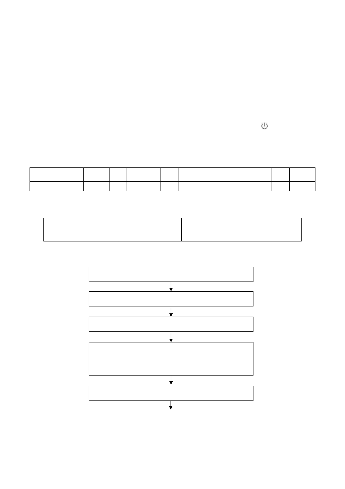
2.2 Adjustment flow chart shown as Fig.1
Check if EDID, HDCP KEY and FLASH have been burned.
Combination adjustment for general assembly
White balance adjustment
Connect to central signal source, check if TV functions are normal
–omitted channel, analog parameters control, etc; check if output of
earphone and speaker is normal.
Input AV or Y/C signal,check if every function is normal.
3
Page 6
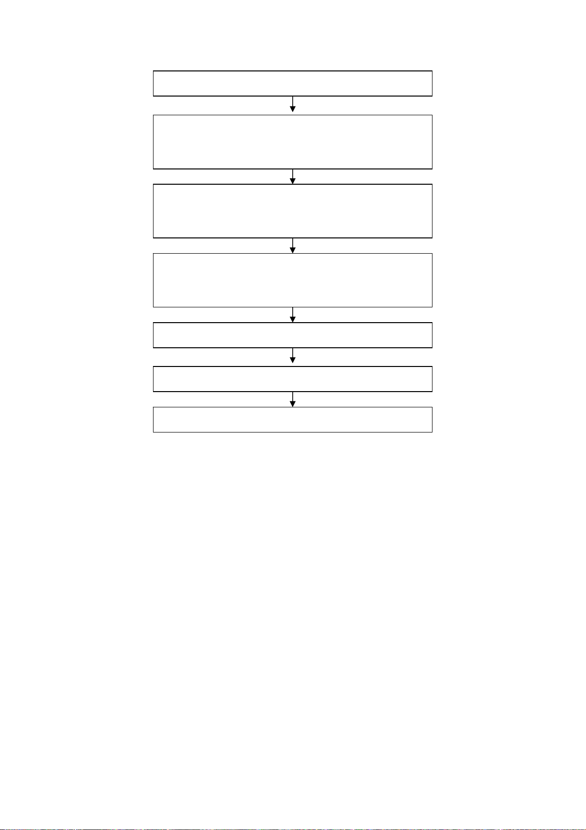
Input YPbPr signal,check if every function is normal.
Input RGB signal,check if the display is normal; check if every
function is normal –analog parameter control, horizontal/vertical
center, etc.
Input HDMI signal,check if the display is normal; check if every
function is normal –analog parameter control, horizontal/vertical
center, etc.
Connect to USB device, check if the display is normal; check if
every function is normal –analog parameter control,
horizontal/vertical center, etc.
Check if other functions are normal –LCN, OTA, etc.
Ex-factory setup
Check accessaries and packing
Fig.1 Adjustment flow chart
3. Alignment instruction
3.1 Unit adjustment
3.1.1 According to the wiring diagram specified by product specification, connect power board,
digital board, IR/key board and backlight board correctly; then power on and check if the
display is normal.
3.1.2 Using method of factory menu
a) First press key “SOURCE”,then press number key “2、5、8、0” in turn to enter into initial
factory menu;
b) Press keys “▲” and “▼” can move cursor to each page of initial factory menu, then press key
“OK” to enter into adjustment menu of each page;
c) Press keys “▲” and “▼” can move cursor upwards and downwards within one adjustment
page;
d) Move cursor to one adjustment item, then press keys “◄” and “►” can adjust it;
e) Press key “MENU” can exit adjustment menu of one page to its superior factory menu;
f) Press key “EXIT” can exit factory menu at any time;
g) Press key “OK” can enter into inferior factory menu;
h) Factory menu item “ADC Calibrate” is used to correct ADC of VGA Component channel;
i) Factory menu item “W/B ADJUST” is used to adjust white balance;
j) Factory menu item “POWER MODE” is used to set power-on mode, “Standby” means the set
4
Page 7

will be in Standby state after power-on; “ Memory ” means the set will in the last power-off
state after power-on ; “ForceOn” means the set will be working automatically after power-on ,
the mode is also used for factory-machine-aging; default setting should be “Standby” mode
unless specified by customer requirement;
k) Factory menu item “ISP MODE” is used to upgraded unit software from VGA port when the
item is set as “ON” and the set is connected to ISP adjustment equipment; DDC function of
VGA port will be recovered when the item is set as “OFF”; the value of the item can not be
kept in the memory, that is to say the item is reset as “OFF” after power-on again;
l) Factory menu item “RESET ALL” is used to reset factory menu data and user menu data;
execute the item then the set will be started up again and the startup guided picture will be
displayed also;
m) Factory menu item “FACTORY CHANNEL PRESET” is used to preset factory programs data;
it is necessary to connect to central signal source for DTV searching programs. Now digital
frequency of central signal CH40(626 MHz) is distributed to HK DTMB programs. Primary
preset programs would not be modified along with the changing of central signals, so please
select item “DTV Manual Tuning” in menu Channel to manual search digital programs, the
process will spend about 15s;
n) Factory menu item “CUSTOM CHANNEL PRESET” : first delete all DTV/ATV programs for
factory adjustment, then preset DTV/ATV channel data according to customer order
requirements; please execute the item to clear out all programs for factory adjustment before
leaving factory;
o) Factory menu item “MST ADJUST”: Default is “OFF”. Engineering sample with RS-232
functions matches the design specifations when the item is set as “OFF”; It’s convenient to
adjust with equipment when it’s set as “ON” the value of the item can not be kept in the
memory, that is to say the item is reset as “OFF” after power-on again;
p) Factory menu item “BACKLIGHT” is used to adjust backlight brightness, test voltage of
13-pin power socket and adjust the item to meet the requirement of maximum PWM voltage
in panel specification; the software having been preset according to model need not be
adjusted;
q) Factory menu item “SSC ADJUST” is used to adjust expended functions of frequency content,
the software having been preset according to model need not be adjusted;
r) Factory menu item “Others”-> “Audio curve” is used to adjust volume curve; the software
having been preset according to model need not be adjusted unless special customer
requirements;
s) Factory menu item “Software upgrade” is used to upgrade USB, after select confirm the
software will search AP.bin stored in USB device to upgrade at any channel ; If the software
has been upgraded or EEPROM has data, please select and execute operation “RESET ALL”
before adjustment for the first time.
3.1.3 ADC correction of Component channel YPbPr
a) Switch to Component channel;
b) Press key “SOURCE”,then press number keys “2、
5、8、0” to enter into initial factory menu;
c) Move cursor to item “ADC Calibrate” and press key “OK” to enter into interior factory menu;
d) Input Component signal (VG-848 Timing:969(PAL),Pattern:918 100% color bar), move
cursor to item “MODE”,press keys “▲” and “▼” to select item “YPbPr(SD)”, then move
cursor to item “AUTO ADC” and press key “OK” to begin adjustment automatically until a
5
Page 8

prompt “success” for adjustment completion is displayed;
e) Input Component signal (VG-848 Timing:972(1080i),Pattern:918 100% color bar), move
cursor to item “MODE”,press keys “▲” and “▼” to select item “YPbPr(HD)”, then move
cursor to item “AUTO ADC” and press key “OK” to begin adjustment automatically until a
prompt “success” for adjustment completion is displayed.
3.1.4 ADC correction of RGB channel
a) Switch to RGB channel (D-SUB channel);
b) Press key “SOURCE”, then press number keys “2、5、8、0” to enter into initial factory menu;
c) Move cursor to item “ADC Calibrate” and press key “OK” to enter into interior factory menu;
d) Input RGB signal (VG-848 Timing:856(1024×768/60 Hz),Pattern:920 8 step Gray), move
cursor to item “MODE”,press keys “▲” and “▼” to select item “RGB”, then move cursor to
item “AUTO ADC” and press key “OK” to begin adjustment automatically until a prompt
“success” for adjustment completion is displayed.
3.2 White balance adjustment
Unless specified by customer, default COOL color temperature is 12000K, chromaticity
coordinates is ( 272、 278 ) ; default Standard color temperature is 9300K, chromaticity
coordinates is(285、293); default Warm color temperature is 6500K, chromaticity coordinates
is (323、329).
3.3 White balance adjustment processes
The set should be working above 30 minutes before white balance adjustment for it would be in a
stabler state. Use white balance apparatus CA-210 and switch to its LCD channel.(19” for
example)
a) Switch to HDMI channel;
b) Press key “SOURCE”, then press number keys “2、5、8、0” in turn to enter into initial factory
menu;
c) Move to item “W/B ADJUST” and press key “OK” to enter into interior factory menu;
d) Input HDMI signal (VG-848 Timing: 856(1024×768/60 Hz),Pattern:921 16 step Gray),
move cursor to item “MODE”, press keys “▲” and “▼” to select item “HDMI”, then move
cursor to item “TEMPERTURE”, press keys “▲” and “▼” to select item “Standard”;
e) Fix item “G GAIN”, adjust item “R GAIN、B GAIN” to set chromaticity coordinates of the 13
step is (285、293);
f) Fix item “G OFFSET”, adjust item “R OFFSET、B OFFSET” to set chromaticity coordinates of
th
step is (285、293);
the 4
g) During adjustment , make sure that color temperature of bright step is (X=285±10,Y=293±15)
and color temperature of dark step is (X=285±10,Y=293±25);
h) Then move cursor to item “COPY ALL” to copy white balance data to the other channels;
i) Check if color temperature of COOL and WARM meet requirements as below:
COOL: allowable error of bright step is (X±5, Y±15), allowable error of dark step is (X±8,Y±30);
WARM: allowable error of bright and dark step are both (X±10,Y±10);
otherwise adjust items “R_GAIN /B_GAIN/R_OFF/B_OFF” to meet requirements and then save
data;
j) Check if the white balance of the other channels meet the requirements, if not, adjust the data
and save separately.
th
6
Page 9
k) Check if the picture of every channel is normal after adjustment;
l) Adjustment rules for reference as below:
adjust B gun: adjust B gun value downwards , then coordinates of X、Y will rise;
adjust B gun value upwards , then coordinates of X、Y will descent;
adjust R gun will effect the coordinate of X and the value of Lv a little:
adjust R gun value upwards , then coordinate of X will rise;
adjust R gun value downwards , then coordinate of X will descent;
adjust G gun will effect the coordinate of Y and the value of Lv a lot:
adjust G gun value upwards , then coordinate of Y will rise;
adjust G gun value downwards , then coordinate of Y will descent;
4. Performance check
4.1 TV functions
Connect RF port to central signal source, first enter into menu Channel, then search programs
automatically, check if there is any omitted program of ATV、DTV, check if the output of speakers
is normal, check if the picture is normal.
4.2 Composite AV or Y/C ports
Input AV signal or Y/C separate S-Video signal, check if the picture and the sound are normal
under the circustances of power-on, switching channel,switching signal format, etc.)
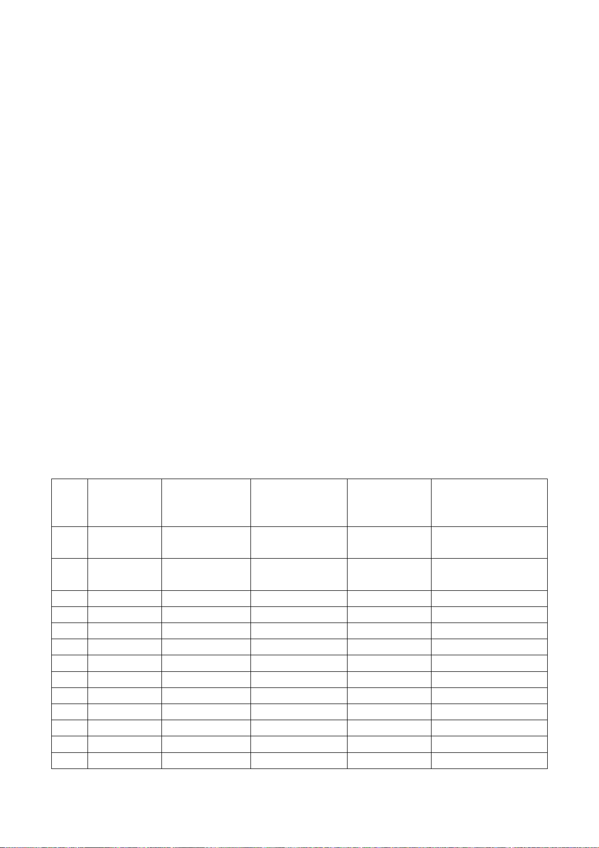
4.3 Component port (Y, Pb, Pr)
Input Component signal from signal generator VG-848 with the formats as Table 3 respectively,
check if the display and the sound are normal under the circumstances of power-on/off, switching
channel, switching signal format, etc.
Table 3 Component receiving signal formats
Horizontal
No. Definition
1 720×480 15.734/15.75 59.94/60 13.5/13.514
2 720×576 15.625 50 13.5
3 720×480 31.469/31.5 59.94/60 27/27.027 480p
4 720×576 31.25 50 27 576p
5 1280×720 37.5 50 74.25 720p (50p)
6 1280×720 44.955/45 59.94/60 74.176/74.25 720p (59.94p/60p)
7 1920×1080 28.125 50 74.25 1080i (50i)
8 1920×1080 33.75 59.94/60 74.176/74.25 1080i (59.94i/60i)
9 1920×1080 26.973 23.976 74.176 1080p (23.97p)
10 1920×1080 27 24 74.25 1080p (24p)
11 1920×1080 28.125 25 74.25 1080p (25p)
12 1920×1080 33.716 29.97 74.176 1080p (29.97p)
13 1920×1080 33.75 30 74.25 1080p (30p)
frequency
(kHz)
Vertical frequenvy
(Hz)
Dot-pulse
frequency
(MHz)
Remark
480i (NTSC,
NTSC4.43,PAL60,PAL-M)
576i (PAL, PAL-N,
SECAM)
7
Page 10
14 1920×1080 56.25 50 148.5 1080p (50p)
15 1920×1080 67.432/67.5 59.94/60 148.35/148.5 1080p (59.94p/60p)
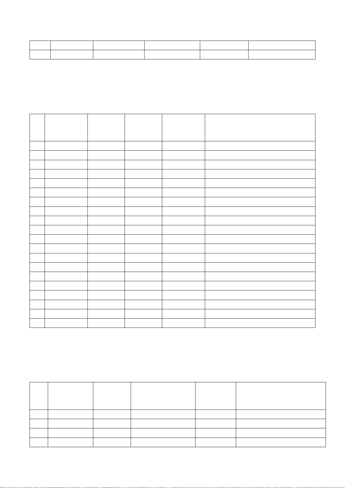
4.4 R,G,B port
Input RGB D-SUB signal from signal generator VG-848 with the formats as Tabl e 4 respectively,
check if the display and the sound are normal under the circumstances of power-on/off, switching
channel, switching signal format, etc. if there is any deviation of line or field, enter into main menu
and select items “Picture->Screen->Auto Adjusting” in turn to correct them automatically.
Table 4 R,G, B receiving signal formats
Horizontal
No. Definition
1 640×480 31.469 59.94 25.175 IBM
2 720×400 31.469 70.086 28.322 IBM
3 640×480 37.861 72.809 31.5 VESA
4 640×480 37.5 75 31.5 VESA
5 800×600 35.156 56.25 36 VESA
6 800×600 37.879 60.317 40 VESA
7 800×600 48.077 72.188 50 VESA
8 800×600 46.875 75 49.5 VESA
9 1024×768 48.363 60.004 65 VESA
10 1024×768 56.476 70.069 75 VESA
11 1024×768 60.023 75.029 78.75 VESA
12 1152×864 67.5 75 108 VESA
13 1280×960 60 60 108 VESA
14 1280×1024 63.98 60.02 108 VESA
15 1280×1024 80 75 135 SXGA
16 1360×768 47.7 60 85.5 WXGA
17 1440×900 55.9 60 106.5 WXGA+
18 1400×1050 65.22 60 122.61 SXGA+
19 1680×1050 65.3 60 146.25 WSXGA+
20 1920×1080 67.5 60 148.5
frequency
(kHz)
Vertical
frequenvy
(Hz)
Dot-pulse
frequency
(MHz)
Remark
4.5 HDMI port
Input HDMI signal from signal generator VG-849 with the formats as Ta ble 5, check if the display
and the sound(32 KHz、44.1 KHz、48 KHz)are normal under the circumstances of power-on/off,
switching channel, switching signal format, etc.
Table 5 HDMI receiving signal formats
Horizontal
No. Definition
1 640×480 31.469/31.5 59.94/60 25.175/25.2 640×480p@59.94/60 Hz
2 720×480 31.469/31.5 59.94/60 27/27.027 720×480p@59.94/60 Hz,4:3/16:9
3 1280×720 44.955/45 59.94/60 74.176/74.25 1280×720p@59.94/60 Hz
4 1920×1080 33.716/33.75 59.94/60 74.176/74.25 1920×1080i@59.94/60 Hz
frequency
(kHz)
Vertical frequenvy(Hz)
Dot-pulse
frequency
(MHz)
Remark
8
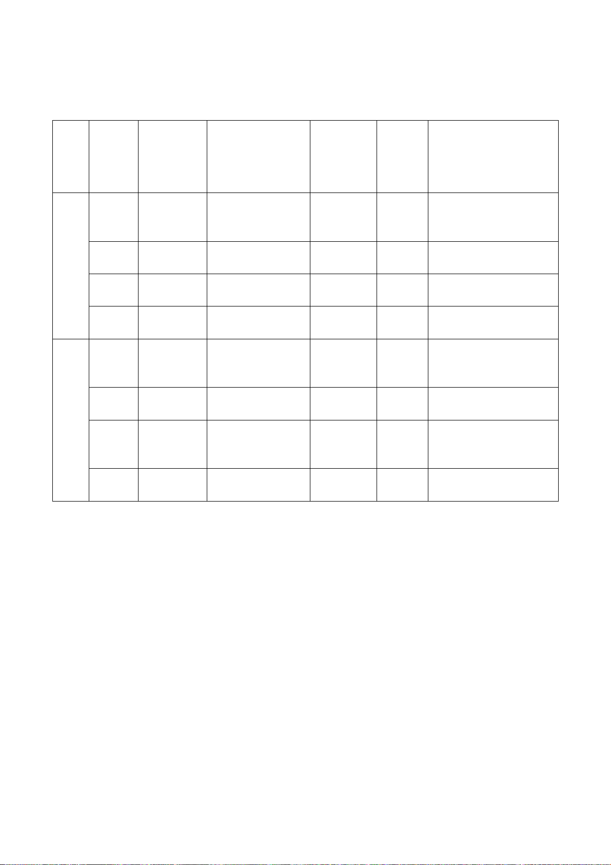
Page 11
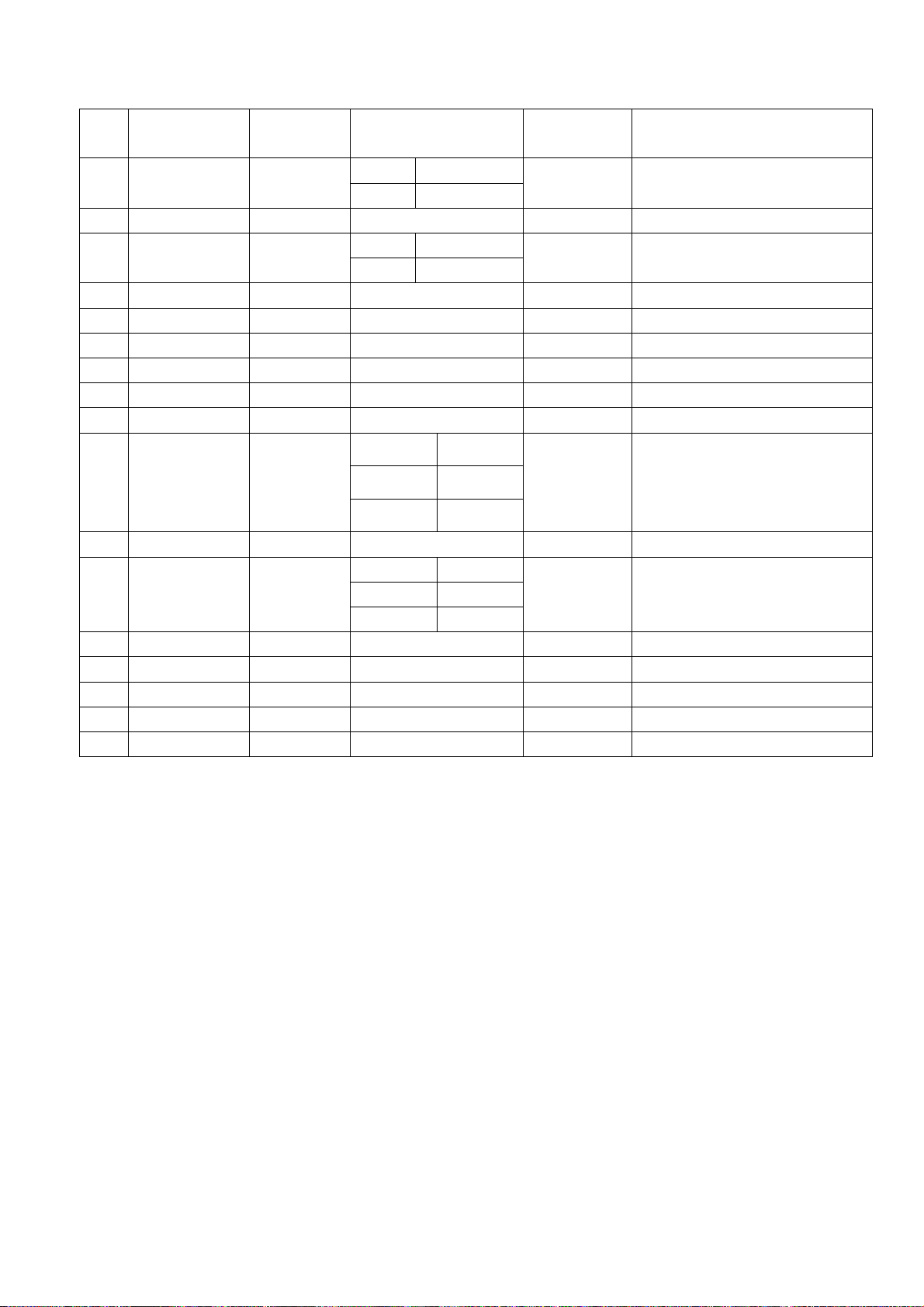
5 720(1440)×480 15.734/15.75 59.94/60 27/27.027
6 720(1440)×240 15.734/15.75
7 (2880)×480 15.734/15.75 59.94/60 54/54.054 (2880)×480i@59.94/60 Hz,4:3/16:9
8 (2880)×240 15.734/15.75
9 1440×480 31.469/31.5 59.94/60 54/54.054 1440×480p@59.94/60 Hz,4:3/16:9
10 1920×1080 67.432/67.5 59.94/60 148.352/148.5 1920×1080p@59.94/60 Hz
11 720×576 31.25 50 27 720×576p@50 Hz,4:3/16:9
12 1280×720 37.5 50 74.25 1280×720p@50 Hz
13 1920×1080 28.125 50 74.25 1920×1080i@50 Hz
14 720(1440)×576 15.625 50 27 720(1440)×576i@50 Hz,4:3/16:9
Mode 1 59.826/59.886
mode 2 60.054/60.115
mode 1 59.826/59.886
mode 2 60.054/60.115
Mode1 49.761
27/27.027
54/54.054 (2880)×240p@59.94/60 Hz,4:3/16:9
720(1440)×480i@59.94/60
Hz,4:3/16:9
720(1440)×240p@59.94/60
Hz,4:3/16:9
15 720(1440) ×288 15.625
16 (2880) ×576 15.625 50 54 (2880)×576i@50 Hz,4:3/16:9
17 (2880) ×288 15.625
18 1440×576 31.25 50 54 1440×576p@50 Hz,4:3/16:9
19 1920×1080 56.25 50 148.5 1920×1080p@50 Hz
20 1920×1080 26.973/27 23.97/24 74.176/74.25 1920×1080p@23.97/24 Hz
21 1920×1080 28.125 25 74.25 1920×1080p@25 Hz
22 1920×1080 33.716/33.75 29.97/30 74.176/74.25 1920×1080p@29.97/30 Hz
Mode2 49.92
Mode3 50.08
Mode1 49.761
Mode2 49.92
Mode3 50.08
27 720(1440)×288p@50 Hz,4:3/16:9
54 (2880)×288p@50 Hz,4:3/16:9
4.6 USB port
Connect the USB device with picture, sound and video documents and check if the picture, sound
and functions are normal.
4.7 Other functions check
a) Check if the functions are normal -timing turn-on/off、sleeping turn-off、picture/sound mode、
OSD、stereo and digital audio interface, etc.;
b) Check if Audio Only digital programs are normal;
c) Check if function of logic channel number (LCN) is normal;
5. User menu setup before leaving factory
Enter into page “LOCK” of user menu and iput the initial password “0000 “, select submenu
“Restore Factory Default” then press “OK“ to preset items before leaving factory as below:
a) Clear out all programs information;
b) Clear out information of block program and favorite channels;
c) Default setup of user analog data;
d) Set Menu Language as Chinese;
e) Set Power on MODE as Standby.
9
Page 12
6. Instruction of factory software burning as Table 6
Table 6 Instruction of factory software burning
Location
size
Below
26”
26”
and
above
No.
NA05 5271280501 MX25L12805DMI-20G
NA02 5272404002 AT24C04 HDCP KEY Yes
NA07 5272402002 AT24C02 HDMI EDID Yes
NB04 5272402002 AT24C02 VGA EDID Yes
N103 5271280501 MX25L12805DMI-20G
N105 5272404002 AT24C04 HDCP KEY Yes
N402
N405
N417
N206 5272402002 AT24C02 VGA EDID Yes
Part No. Part type
5272402002 AT24C02 HDMI EDID Yes
Note 1: Write-protect setup method
Enter into interface of burning
Setting”, set item “Protect” as “All Protect”. Be sure to select item “Config” before burning
software, and write-protect must be re-set after burning program ALL-100 startup every time.
Instruction
of software
function
Main
program
Main
program
program ALL-100, select item “Config”, press item “config
Burned
before
SMT
Yes
Yes
Burning method
burned with program
ALL100, write-protect setup,
refer to Note 1 in detail
burned with program
ALL100
burned with program
ALL100
burned with program
ALL100
burned with program
ALL100, write-protect setup,
refer to Note 1 in detail
burned with program
ALL100
burned with program
ALL100
burned with program
ALL100
Note 2: Burning and upgrading software method with burning tool ISP
1) Main board upgrading: connect 4-core line of burning tool ISP to Debug port(location No. XM04
for below 26” and No. X505 for 26” and above)of main board;
Unit upgrading: connect both VGA ports between burning tool ISP and main board, then enter into
factory menu and set item “ISP Mode” as “ON”;
2) Use on-line burning tool of Mstar, enter into menu “Device”, select item “WP Pin pull to high
during ISP” as Fig. 2 to make sure hardware write-protect of Flash is canceled and the erasing
process will be normal;
10
Page 13
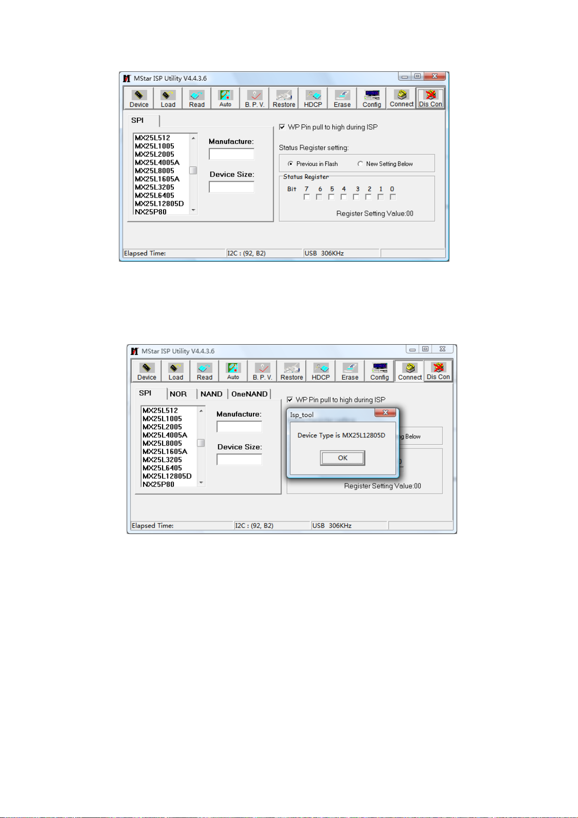
Fig. 2 Write-protect setup
3) Select menu “Connect”, a dialog “Device Type is MX25L12805D” will be displayed as Fig. 3
to show succeeding in connecting. If failing to connecting, select the first menu “Device” and
manual select item “MX25L1280D”, then press key “Connect”.
Fig. 3 Successful connection
4) Press key “Read”,select burning file (for example MERGE.bin) as Fig. 4.
11
Page 14
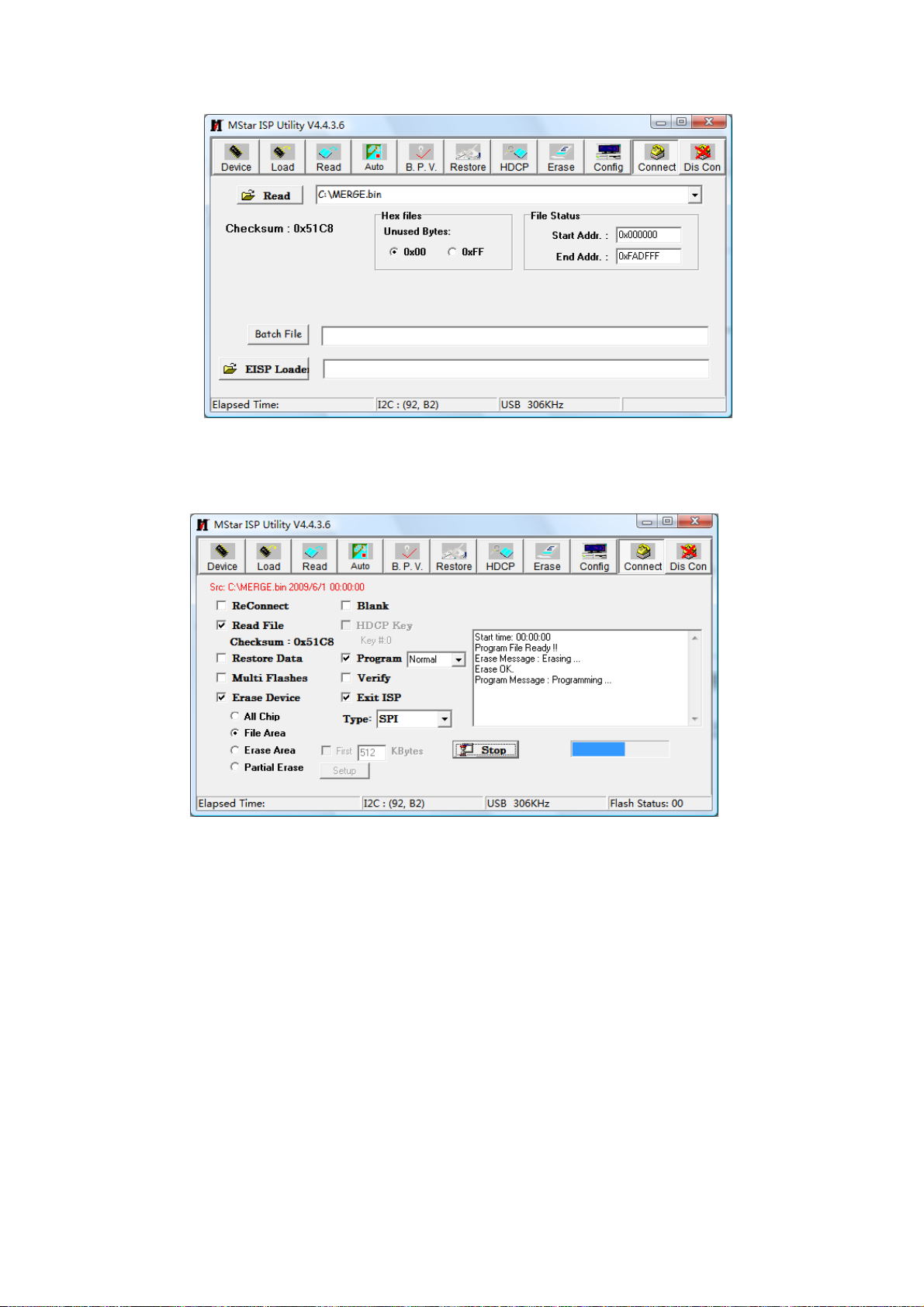
Fig. 4 Burning file
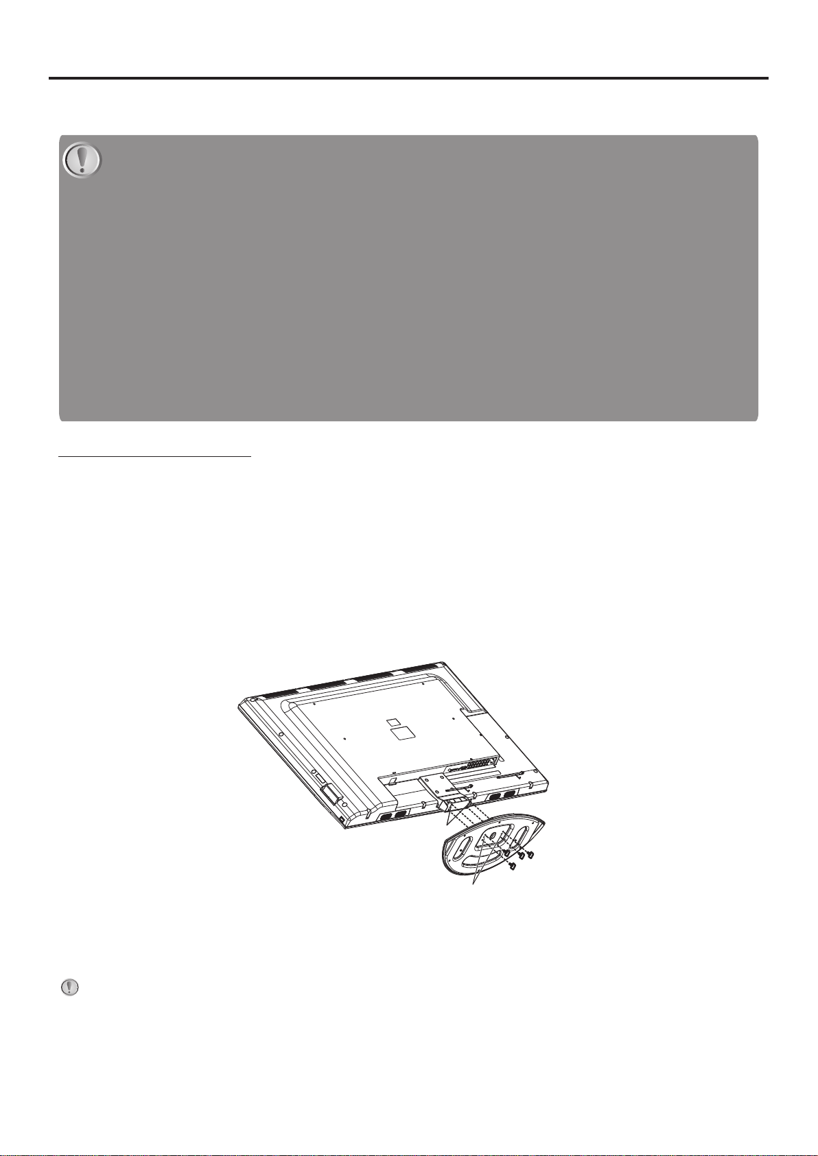
5) Select menu “Auto”, then select items “All chip”, “program” and other switches as Fig. 5
Fig. 5 Switches
6) Press key “Run” as Fig. 4 to begin burning software, there are two steps for the process: Erase
and Program, normal burning processes are as follows:
the first course “Erasing…” will be lasting for a moment, otherwise skipping over means
unsuccessful erasing; please confirm process (2) and then burn software again;
the following course “Programming…” will be done until a prompt “Pass” is displayed.
7) A prompt “Pass” will be displayed beside the key “Run” for successful burning as Fig. 6
12
Page 15

Fig. 6 A prompt “Pass” beside the key “Run” for successful burning
8) Need not exit from ISP burning interface and only repeat the process 3)and 5)to go on burning
software for other sets.
Note 3: On-line burning and upgrading method from a USB port
1) Be sure to format a USB disk as FAT32;
2) Copy program file to the USB disk with the name “AP.bin”;
3) Power on, press key “SOURCE” and number keys “2, 5, 8, 0” in turn to enter into initial factory
menu;
4) Enter into factory menu item “software upgrade”, select “confirm” to search AP.bin stored in
USB disk automatically to upgrade the software; upgrade progress is below:
A、Reading USB disk,a prompt “ Searching USB” will be displayed and an USB disk indicator light
twinkling ;
B、Burning Flash, prompts “Updating! Please don’t power off!!!” and “upgrading schedule” will be
displayed at the same time, after the burning process completed the set will re-start automatically.
5) Start up the set again, enter into factory menu to confirm software version and time parameters;
then execute “RESET ALL” to complete the whole burning process.
6) Method of burning from USB could not be sure to be suitable for all kinds of USB disks, so please
try other USB disks if necessary.
13
Page 16

Block diagram
Working principle analysis of the unit
1. PAL/SECAM signal flow
PAL/SECAM signal from antenna is inputted into TUNER FQD1116 which is an
analog-digital-integrative model, the RF signal is demodulated by the TUNER, then CVBS signal and
audio difference IF signal SIF are outputted. TUNER FQD1116 is controlled by main chip MSD209
through I2C bus.
TV CVBS signal is inputted into main chip MSD209 directly to be processed by modules “VIDEO
DECODER, DEINTERLACE , VIDEO PROCESS and SCALER”, then LVDS signal is outputted to drive
LCD panel.
SIF audio signal is inputted into main chip MSD209 directly and processed by modules of
demodulation, pre-amplification, acoustic effect processing and volume control, then the audio signal are
inputted into earphone amplifiers BH3547F to be amplified and then be divided to two signals, one is
outputted to earphone jack, the other is inputted into D class audio power amplifier R2A15112FP to be
amplified and then be outputted to speakers.
2. DTMB signal flow
DTMB signal from antenna is inputted into TUNER FQD1116 to be lower frequency convterted, then
different IFsignal is outputted to deodulating chip LGS-8G42 to be demodulated and then be inputted
into main chip MSD209 with format of standard serial or parallel transport stream for de-multiplyiing and
decoding.
Video route: de-multiplex digital video signal is decoded and vidio processed by main chip MSD209
and then output LVDS signal to drive the panel.
Audio route: de-multiplex digital audio signal is decoded and audio processed by MSD209, then
14
Page 17

output dual-track (stereo) analog audio signal. via MSD209 pre-amplifying, sound processing and
volumn control, the signal is sent into earphone amplifier BH3547 to be amplified, then output two ways ;
one way is sent to earphone jack directly, the other is inputted into class-D audio power amplifier
R2A15112FP to be amplified and then outputted to speakers.
3. AV input signal flow
AV video signal is inputted into main chip MSD209 directly and processed by modules of “VIDEO
DECODER, DEINTERLACE, VIDEO PROCESS and SCALER”, then LVDS signal is outputted to drive
LCD panel.
AV audio signal is processed by circuits of “voltage divided, impedance matching and
alternating-current coupling”, then inputted into main chip MSD209 directly for acoustic process and
volume control, then inputted into earphone amplifier BH3547F to be amplified, now the audio signal is
divided into two ways, one is outputted to earphone jack directly, the other is inputted into class-D
audio power amplifier R2A15112FP to be amplified and then outputted to speakers.
4. D-SUB/YPbPr signal flow
D-SUB, YPbPr video signal inputted into main chip MSD209 to be processed by modules of “A/D
transform, video decode, deinterlace, video process and scaler”, then LVDS signal is outputted to drive
LCD panel.
D-SUB, YPbPr audio signal is processed by circuits of “voltage divided, impedance matching and
alternating-current coupling”, then inputted into main chip MSD209 directly for acoustic process and
volume control, afterwards the audio signal is inputted into earphone amplifier BH3547F directly to be
amplified, now the audio signal is divided into two ways, one is outputted to earphone jack directly, the
other is inputted into class-D audio power amplifier R2A15112FP to be amplified and then outputted to
speakers.
5. HDMI signal flow
HDMI video signal inputted into main chip MSD209 to be processed by modules of “video decode,
video process and scaler”, then LVDS signal is outputted to drive LCD panel.
HDMI audio signal is inputted into main chip MSD209 directly for sound process, pre-amplify,
acoustic process and volume control, then the audio signal is inputted into earphone amplifier BH3547F
directly to be amplified, now the audio signal is divided into two ways, one is outputted to earphone jack
directly, the other is inputted into class-D audio power amplifier R2A15112FP to be amplified and then
outputted to speakers.
6. AV output signal flow
The present video signal is outputted after processed by MSD209 modules of decoding circuit and
peripheral video amplifying circuit. The present audio signal is processed by MSD209 modules of
pre-amplification, acoustic effect processing and volume control, then sent to operational amplifier
amplify and output.
7. SPDIF signal flow
The present audio signal is outputted after processed by MSD209 modules of acoustic effect
processing, volume control and digital sound decode.
15
Page 18

IC block diagram
1. MSD209
16
Page 19

Twin-turbo 8051 Micro-controller
Transport Stream De-multiplexer
MPEG-2 A/V Decoder
MPEG-4 Decoder
H.264 Decoder
NTSC/PAL/SECAM Video Decoder
Multi-Standard TV Sound Processor
Digital Audio Interface
Analog RGB Compliant Input Ports
VIF Input Support
DVI/HDCP/HDMI Compliant Input Port
High-Performance Scaling Engine
Auto-Configuration/Auto-Detection
Video Processing & Conversion
Output Interface
CVBS Video Output
2D Graphics Engine
17
Page 20

2. LG-8G42-A1
The LGS-8G42-A1 is a single chip demodulator fully compliant with GB20600-2006 standard. It uses
TDS-OFDM (Time Domain Synchronous-Orthogonal Frequency Division Multiplexing), a core
technology on which the China Digital Television Terrestrial Broadcasting System Standard
(GB20600-2006) is based. Designed for digital terrestrial reception of high definition, standard
definition and other multimedia-based services, the demodulator is intended for indoor, outdoor, fixed,
portable and automotive applications.
The chip takes an analog or digital IF signal as input, converts to baseband and then performs the
necessary demodulation and FEC (forward error correction) decoding, and then provides an MPEG-2
transport stream output in parallel or serial format. With an external time de-interleaver memory, a
complete GB20600-2006 RF to MPEG front-end can be designed.
z Optimized GB20600-2006 compliant single chip demodulator
z Supports 64QAM, 32QAM, 16QAM, 4QAM, and 4QAM-NR modulation
z FEC rates of 0.4, 0.6, or 0.8 and guard intervals of PN420, PN595, and PN945.
z Time De-interleaving: M=240 or M=720.
z Automatic parameter discovery & update
z Integrated 10-bit ADC.
z RF input signal
-digital IF signal
-analog IF signal
z Signal output
-MPEG transport stream of SPI specification
-support output signal in parallel or serial format
z Self-recover function
-resumption lost signal without performing external program
-signal unlocked after pulse noise suppression
-rapid capture time
z Low power consumption
-lower 280mW in normal mode
z Excellent active echoes suppression
18
Page 21

z Good single-frequency function
z Optimized for maximum signal resiliency in all conditions (impulse noise, echoes, fading, etc.)
z Full I
z Complies with RoHS requirements (Pb-free, or Green)
z Support digital IF signal and digital baseband IQ input
z Standard I
z MPES-TS port connect to MPEG decoder
2
C bus support
2
C ports control
3. R2A15112FP
R2A15112FP is a Digital Power Amplifier IC developed for TV.
R2A15112FP has a maximum power of 15W(typ) × 2ch.(VD = 24V,THD = 1%, SE) at a 4 Ω load.
It is possible to replace a conventional analog amplifier with a digital amplifier easily.
Feature
●Maximum power out put (No external heat sink)
(note) These apply when the thermal pad is soldered to the printed-circuit board directly.
Recommended Power Condition
SE operation mode :15Wx2ch(VD=24V,4Ω load,THD+N:1%)
BTL operation mode:30Wx1ch(VD=21V,8Ω load,THD+N:10%)
●Highly efficient, low noise, and low distortion
●Popless
●Built-in protection - Overcurrent, overheat, and undervoltage
●Built-in Mute and Standby function
●The gain can be changed to four settings by two terminals.
19
Page 22

Trouble shooting
1. Fault clearance
Before servicing please check to find the possible causes of the troubles according to the table
below.
1.1 Antenna (signal):
Picture is out of focus or jumping z Bad status in signal receiving
z Poor signal
z Check if there are failures with the electrical connector or
the antenna.
z Check if the antenna is properly connected.
Fringe in picture z Check if the antenna is correctly oriented.
z Maybe there is electric wave reflected from hilltop or
building.
Picture is interfered by stripe shaped
bright spots
There appear streaks or light color
on the screen
1.2 TV set:
Symptoms Possible cause
Unable to switch the power on z Check to see if the power plug has been inserted properly
No picture and sound z Check to see if the power supply of liquid crystal TV has
Deterioration of color phase or color
tone
Screen position or size is not proper z Check is the screen position and size is correctly set up.
Picture is twisted and deformed z Check to see if the picture-frame ratio is properly set up.
Picture color changed or colorless z Check the “Component” or “RGB” settings of the liquid
z Possibly due to interference from automobile, train, high
voltage transmission line, neon lamp etc.
z Maybe there is interference between antenna and power
supply line. Please try to separate them in a longer
distance.
z Maybe the shielded-layer of signal wire is not connected
properly to the connector.
z Check if interfered by other equipment and if interfered
possibly by the equipment like transmitting antenna,
non-professional radio station and cellular phone.
into the socket.
been switched on. (As can be indicated by the red LED at
the front of the TV set)
z See if it’s receiving the signal that is transmitted from other
source than the station
z Check if it’s connected to the wrong terminal or if the input
mode is correct.
z Check if the signal cable connection between video
frequency source and the liquid crystal TV set is correct.
z Check if all the picture setups have been corrected.
crystal TV set and make proper adjustment according to the
20
Page 23

signal types.
Picture too bright and there is
distortion in the brightest area
z Check if the contrast setting is too high.
z Possibly the output quality of DVD broadcaster is set too
high.
z It maybe also due to improper terminal connection of the
video frequency signal in a certain position of the system.
Picture is whitish or too bright in the
darkest area of the picture
z Check if the setting for the brightness is too high
z Possibly the brightness grade of DVD player (broadcaster)
is set too high.
No picture or signal produced from
the displayer if “XXX in search”
appears.
There appears an indication -
“outside the receivable scope)
z Check if the cable is disconnected.
z Check if it’s connected to the proper terminal or if the input
mode is correct.
z Check if the TV set can receive input signal. The signal is
not correctly identified and VGA format is beyond the
specified scope.
Remote control cannot work
properly
z Check if the batteries are installed in the reverse order.
z Check if the battery is effective.
z Check the distance or angle from the monitor.
z Check if there is any obstruct between the remote control
and the TV set.
z Check if the remote control signal- receiving window is
exposed to strong fluorescence.
No picture and sound, but only
hash.
z Check if the antenna cable is correctly connected, or if it
has received the video signal correctly.
Blur picture z Check if the antenna cable is correctly connected.
z Of if it has received the right video signal.
No sound z Check if the “mute” audio frequency setting is selected.
z Check if the sound volume is set to minimum.
z Make sure the earphone is not connected.
z Check if the cable connection is loose.
When playing VHS picture search
tape, there are lines at the top or
bottom of the picture.
z When being played or in pause VHS picture search tape
sometimes can’t provide stable picture, which may lead to
incorrect display of the liquid crystal TV, In this case please
press “auto” key on the remote control so as to enable the
liquid crystal TV set to recheck the signal and then to
display correct picture signal
21
Page 24

2. Troubleshooting guide
2.1. No raster
POWER button on RC or
the set and check the
indicator light
Blue
Is X501-1#
on the main board high
voltage ?
Yes
No
Check backlight
circuit of power
board and
backlight board
Check backlight
control circuit on
digital board
Press
power supply, check if the
red indicator is light in the
Yes No
Red
Is X501-13#
on the main board high
voltage ?
Yes
Check standby
circuit
No
Turn-on
STANDBY?
of X501-11# on the main
board is normal ?
Yes
Check the
circuit of IR
board
Check standby
control circuit
on digital
board
Check if 5V-S
No
Check the
circuit of
power
standby
22
Page 25

2.2. Raster, but no picture
Y
Y
Is there no
Yes
signal in each
channel?
No
Check the
circuit of each
channel
factory menu and perform
E2PROM initiallization,
restart the set and check if
has picture ?
Yes
OK
Enter the
Does
Remote
Control or keys
operate the set ?
es
Press MEMU
Button, is the display
Normal?
es
No
Check the
corresponding
circuit.
No
Yes
Check LVDS
No
Check the
digital board
Is X508-1#
12V?
Check T-CON
power supply
23
Page 26

2.3. Picture, but no sound
Y
Y
Y
Y
N511-10#,27 is high level?
Check if
Check if
N511-12#,25# input
signal?
es
Check if
N511-4#,5#,32#,33# are
24V?
es
No
Check the circuit
around the sound
amplifier
No
Check 24V power
supply on power
board and other
circuits
Check if
N301-3#,5# input signal?
es
Check the circuit
of earphone
amplifier
No
es
No
Check the mute
circuit of the sound
amplifier
Check the sound
output circuit of
the main chip
24
Page 27

Wiring Diagram
Page 28

Memory
Page 29

RF
Page 30

AV
Page 31

AV PORT
Page 32

Page 33

ABCDEFGH
TP1
D[0-7]
1
5V
X1
1
VCC
2
GND
3
IRQ
GND/THD
4
5
SCL
6
SDA
5V
LED1
5V
2
3
LED2
LED3
LED4
LED5
LED6
LED7
LED8
D[0]
D[1]
D[2]
D[3]
D[4]
D[5]
D[6]
D[7]
D[0-7]
R1
0
R2
0
C1
12p
D[0-7]
KEY
SCL
SDA
C2
12p
VOL-
PAD6
CH+
PAD5
5V
AS1117-3V3
IN OUT
5V
C3
10u
INPUT
PAD3
MENU
PAD8
CH-
PAD4
R3
NC
0
N1
V33
BG1608B121
C4
1u
POWER
PAD2
PAD1
RESERVE
1
CIN1
2
CIN2
3
CIN3
4
CIN4
5
CIN5
6
CIN6
7
CIN7
8
CIN8
9
CIN9
10
CIN10
AVCC
L1
PAD7
VOL+
D[0]
D[7]
D[6]
CIN1112CIN12
11
R4
100
C5
100p
D[1]
37
38
NC
THD139THD040CIN0
GND
VSHILD14VBIAS15AVSS16AVCC17GPIO1218GPIO1119GPIO1020DVCC
13
C6
100n
AVCC
TP2
D[3]
D[4]
D[2]
33
GPIO334GPIO235GPIO136GPIO0
N2
IT7230AFN
AVCC
C7
100n
GPIO432DVSS
31
GPIO5
GPIO6
GPIIO7
GPIO8
GPIO9
V33
C8
100n
INT#
SCLK
ADD0
ADD1
D[5]
V33
V33
R5
R6
10K
30
29
28
27
26
SDA
25
24
23
22
21
10K
R7
3.6K
5.6K
R13
SDA
SDA
SCL
R8
NC
10K
R9
20K
R10
2K
R11
1K
R12
0
5.6K
V33
R14
KEY
KEY BOARD
+3.3V
4
10V
22uF
C901
C902
100n
GND
N902
HRM138CB5400
Vout
GND
Vcc
5
R901
N901
ISL29001
1
2
3
100K
GND
GND
VDD
GND
REXT4PD
SDA
SCL
6
5
LED901
GHZRB703D0
R
+3.3V
R904
2.7K
2.7K
22uF
V901
BC847AW
R911
1.1K
R905
SDA
SCL
TJC10S-07AW
SCL
7
SDA
6
VCC_3.3V
X903
5
4
3
2
1
IR
VCC_5V
GND
LED
+3.3V
R913
47
3K
R914
GND
R912
3K
GND
IR BOARD
R902
100
R903
100
GND
10V
C912
100n
C911
GND
B
TITLE: DWG NO.
KEY BOARD
IR BOARD
6
DRAWN BY
APPROVED BY
9232KH5101DL
REV.
Sheet to
XIAMEN OVERSEAS CHINESE
ELECTRONIC CO., LTD.
A1.0
96
XOCECO
Page 34

Power
Page 35

APPENDIX-A: Main assembly 9246KE5213 LCD-46XR10DKH
NAME NO.
Data processing board
IR board
Touching key board
Power board
Remote control
Panel
XI6KE02169C0
XI6KE02209A0
XI635KH00901
XI6KH0092010
XI6010900401
XI5203468301
N101
N201
N103
N511
N106 N107
TUNER201
RC-904-0A
T460HW03 VF
MAIN COMPONENT AND IT'S NO.
MSD209GL-LF (5270209002)
LGS-8G42 (5270842001)
IC_MX25L128 (5271284501)
IC_R2A15112 (5271511201)
K4T51163QI-HCF7 (5275116302)
TUNER _FQD1116M (5524000029)
Page 36

APPENDIX-B: Exploded view (LCD-46XR10DKH)
Page 37

PART LIST OF EXPLODED VIEW
REF.No. DESCRIPION
1 Front cabinet assembly
2
3 Key bracket
4
5
6
7
8
9 Power board assembly
10 Interface baffle (down)
11 Main board assembly
12
13
14
15
16
17
Display panel
Power switch
Wall mounting bracket (left)
Back cover assembly
Pedestal assembly
Standing pole assembly
Interface baffle (right)
Panel holder assembly
Wall mounting bracket (right)
Touching key board assembly
Sound box assmelby
IR assembly
Note: design and specification are subject to change without notice.
Page 38

PART LIST
LCD-46XR10DKH ver.1.0
REF.No. PARTS No. DESCRIPION Q'TY REMARK
1
2
3
4
5
6
7
8
9
10
11
12
13
14
15
16
17
18
19
20
21
XI6646521100
XI5203468301
XI58B0043410
XI5293000060
XI58A0084100
XI674652L060
XI6151226000
XI6156111000
XI6KH0092010
XI5810G7220A
XI6KE02169C0
XI5810G72110
XI6153269000
XI58A0084200
XI635KH00901
XI6170843000
XI6KE02209A0
XI6010900401
XI5944038500
XI60Z0000699
XI60Z0000700
Front cabinet assembly 1
Display panel
Key bracket 1
Power switch
Wall mounting bracket (left)
Back cover assembly
Pedestal assembly
Standing pole assembly
Power board assembly 1
Interface baffle (down) 1
Main board assembly 1
Interface baffle (right)
Panel holder assembly
Wall mounting bracket (right)
Touching key board assembly
Sound box assmelby
IR assembly
Remote control
User manual
Backlight board
Logical board
1 T460HW03 VF
1
1
1
1
1
1
1
1
1
1
1
1
1
1
1
Only the parts in above list are used for repairing.
Other parts except the above parts can't be supplied.
Page 39
Assemble & Disassemble the Pedestal Base (Option)
If the stand is provided, please read these instructions thoroughly before attempting this installation.
Safety Precautions:
1.Please read these instructions thoroughly prior to attempting this installation.
2.Be sure to handle this product very carefully when attempting assembly. If you are unsure of your
capability, or the use of tools necessary to complete this activity, refer to a professional installer or
service personnel. The manufacturer is not responsible for any damages or injuries that occur due to
mishandling or improper assembly/installation.
3.When using a table or bench as an aid to assembly, be sure to put a soft cushion or covering to prevent
accidental scratching or damage to the unit's finish.
4.The speaker is not intended to support the weight of this display. Do not move or handle this product
from the speaker; which can cause damage to the display not covered under the manufacturer's
warranty.
Installing the Stand
1. Remove the stand from the box and place it on a table or bench.
You must pay attention to the direction of the stand. The wide portion of the stand should go towards the
front of the TV.
2. Lay your TV flat (screen down) on the edge of a table or bench. Make sure that you put down a soft
cushion or cloth so that your TV is not scratched.
3. Put the stand close to the TV back, align the stand with the TV by moving the stand steadily until the Stand
Locators align with the locating grooves on the stand. And align the screw holes on the TV back with the
holes in the stand, then secure the stand to the TV with provided screws.
Locators
Stand
Locating grooves
Secure with
four screws
To remove the stand from the TV, perform these steps in reverse order.
NOTE:
1.Appearance of this product in illustrations may differ from your actual product, and is for
comparative purposes only.
2.Design of this accessory or display products are subject to change without notice.
Page 40

WALL MOUNTING INSTRUCTIONS
Safety Precautions:
1. Be sure to ask an authorized service personnel to carry out setup.
2. Thoroughly read this instruction before setup and follow the steps below precisely.
3.The wall to be mounted should be made from solid materials. Only use accessories supplied by the manufacturer.
4.Very carefully handle the unit during setup. We are not liable for any damage or injury caused by mishandling or improper installation.
5.Be sure to place the unit on a stable and soft platform which is strong enough to support the unit.
6.Do not uplift the speaker when moving the display. The appearance of the unit may different from the actual ones.
7.Design and specifications are subject to change without notice.
8. Retain these instructions for future reference.
Note: All the wall mounting parts are
optional and may be unavailable in
your model.
Below we will show you how to mount the
Display on the wall using our company’s
wall mounting components.
Take out these
parts from the
box
Combination Screw
Fig.1
1. There are three options of wall mounting
ho ld er w it h different sp ec if ic at io ns
:200200,200400,200600. Please check your
wall mounting holder for its specification.
Wall Mounting Holder
Wall Mounting Connector
Expansion Bolt
Wood Screw
Wall mounting fix-h ole c ent er
X
8
200 27
Rea r wall mounting hole center
Fig.2
2. Due to the wall mounting fix-groove leaning to the
right side, the whole unit will lean to right side after
installation, please carefully measure the position of
the holes you want to drill, refer to the parameters
on Fig.2 when drilling the holes.
Note: The "X" in Fig.2 represents a data. It may be
200mm or 400mm or 600mm.
(Unit:mm)
Wall
Fig.3 a
3a. Screw 4pcs expansion bolts to fix the
wall mounting holder on the wall.
Wall
Fig.3 b
3b. If your wall is a wooden structure, please
fix the wall mounting holder on the wall
with 16pcs wood screws.
Fig.4
4. Use the 4pcs combination screws to fix
the wall mounting connector to the rear
of the display unit.(Caution:the direction
of the connectors should be strictly
confirm to the diagram illustrated above).
Fig.5
5. Put the back of the display unit close to the wall
mounting holder, insert the four wall mounting
connectors into the four calabash-shaped holes on
the wall mounting holder. (Fig.5)
Fig.6
6. Let the display unit slowly slide down to
the end of the calabash-shaped hole.
(Fig.6)
8. If you want to dismount the unit do the above steps in reverse order.
7. Push rightwards carefully until the wall
mounting connectors fully slide into the
right fix-grooves and be sure the mounting
is secure.
Fig.7
Page 41

December, 2010
 Loading...