

Sanyo LCD-32E3, LCD-42E3, LCD-26E3, LCD-19E3 User Manual
CAUTION
RISK OF ELECTRIC SHOCK DO NOT OPENN
CAUTION : TO REDUCE THE RISK OF ELECTRIC SHOCK, DO
NOT REMOVE COVER (OR BACK). NO USER-SERVICEABLE
PARTS INSIDE. REFER SERVICING TO QUALIFIED SERVICE
PERSONNEL.
TH IS SY MB OL I ND IC ATE S TH AT DA NGE RO US
VO LTAG E CON ST IT UTI NG A R IS K OF ELE CTRI C
SHOCK IS RESENT WITH THIS UNIT.
T HI S S Y MB OL I ND IC ATE S T HA T T HE RE AR E
IM PO RTA NT OP ER AT IN G AN D M AI NT ENA NC E
INS TRUC TIONS IN THE OW NER’ S MANUA L WITH
THIS UNIT.
WARNING: TO REDUCE THE RISK OF FIRE OR ELECTRIC SHOCK, DO NOT EXPOSE THIS
APPLIANCE TO RAIN OR MOISTURE.
IMPORTANT SAFETY INSTRUCTIONS
1. Read these instructions.
2. Keep these instructions.
3. Heed all warnings.
4. Follow all instructions.
5. Do not use this apparatus near water.
6. Clean only with a dry cloth.
7. Do not block any ventilation openings. Install in
accordance with the manufacturer's instructions.
8. Do not install near any heat sources such as
radiators, heat registers, stoves, or other apparatus
(including amplifiers) that produce heat.
9. Do not defeat the safety purpose of the polarized
or grounding- type plug. A polarized plug has two
blades with one wider than the other. A grounding
type plug has two blades and a third grounding
prong. The wide blade or the third prong are
provided for your safety. If the provided plug does
not fit into your outlet, consult an electrician for
replacement of the obsolete outlet.
10. Protect the power cord from being walked on
or pinched, particularly at plugs, convenience
receptacles, and at the point where they exit from
the apparatus.
11. Only use the attachments/accessories specified by
the manufacturer.
12. Use only with the cart, stand, tripod,
bracket, or table specified by the
manufacturer, or sold with the
apparatus. When a cart is used,
use caution when moving the cart/
appliance combination to avoid injury from tip-over.
13. Unplug this apparatus during lightning storms or
when unused for long periods of time.
14. Refer all servicing to qualified service personnel.
Servicing is required when the appliance has been
damaged in any way, such as when a power-supply
cord or plug is damaged, liquid has been spilled or
objects have fallen into apparatus, the apparatus has
been exposed to rain or moisture, does not operate
normally, or has been dropped.
15. If an outside antenna is connected to the television
equipment, be sure the antenna system is grounded
so as to provide some protection against voltage
surges and built up static charges. In the U.S.
Selection 810-21 of the National Electrical Code
provides information with respect to proper grounding
of the mast and supporting structure, grounding
of the lead-in wire to an antenna discharge unit,
size of grounding conductores, location of antenna
discharge unit, connection to grounding electrodes,
and requirements for the grounding electrodes.
16. An outside antenna system should not be located in
the vicinity of overhead power lines or other electrical
light or power circuits, or where it can fall into such
power lines or circuits. When installing an outside
antenna system, extreme care should be taken to
keep from touching such power lines or circuits as
contact with them might be fatal.
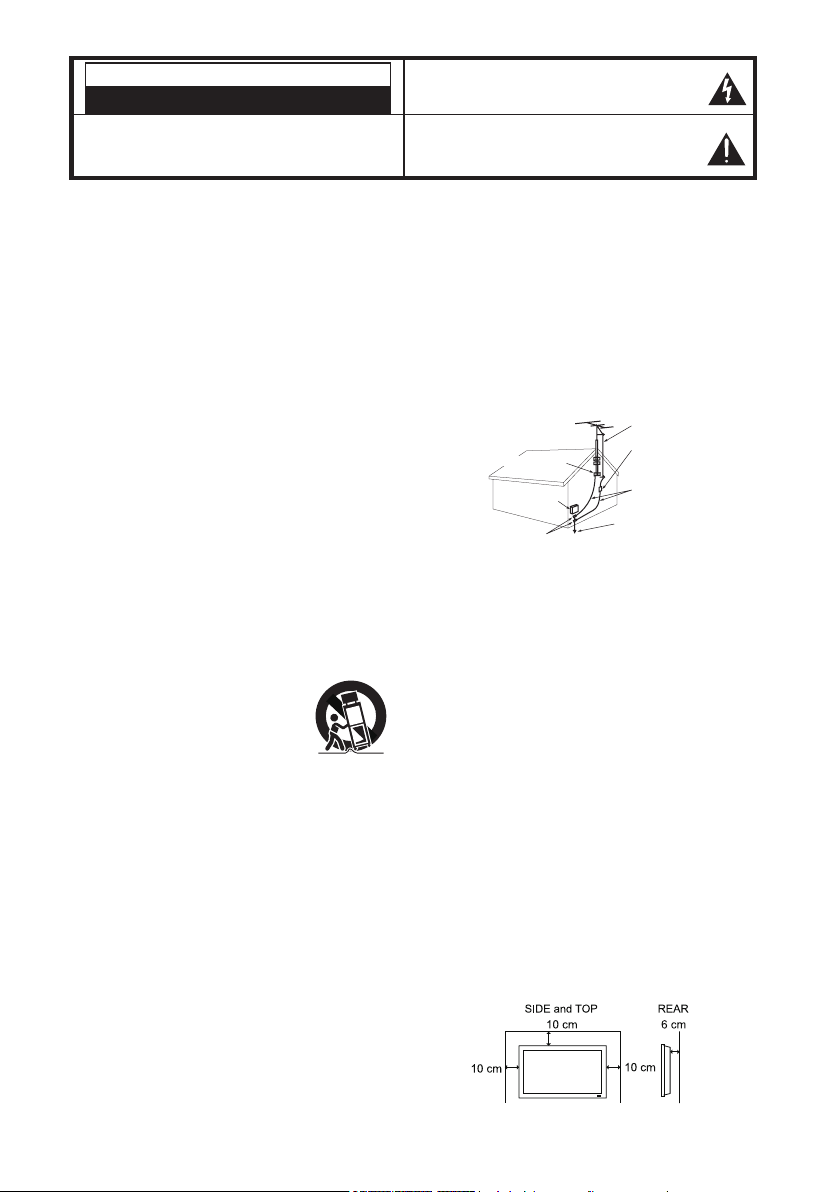
EXAMPLE OF ANTENNA GROUNDING ACCORDING
TO NATIONAL ELECTRICAL CODE, ANSI/NFPA 70
ANTENNA LEAD IN WIRE
ANTENNA DISCHARGE UNIT
GROUND CLAMP
GROUND CLAMPS
NEC- NATIONAL ELECTRICAL CODE
” Note to CATV system installer:
This reminder is provided to call the CATV system installer's
attention to Article 820-40 of the NEC that provides guidelines for
proper grounding and, in particular, specifies that the cable ground
shall be connected to the grounding system of the building, as
close to the point of cable entry as practical.
(NEC SECTION 810-20)
GROUNDING CONDUCTORS
(NEC SECTION 810-21)
POWER SERVICE GROUNDING
ELECTRODE SYSTEM
NEC ART 250, PART H)
17. Wall or Ceiling Mounting - The product should be
mounted to a wall or ceiling only as recommended
by the manufacturer and listed by an independent
laboratory (such as UL).
18. “
Apparatus shall not be exposed to dripping or
splashing and no objects filled with liquides, such as
vases, shall be placed on the apparatus.”
19. When the MAINS plug is used as the disconnect
device, the disconnect device shall remain readily
operable.
20. Install the LCD TV in a proper position. If not, it may
result in a fire hazard.
21. Provide appropriate space on the top, sides and rear
of the LCD TV cabinet for allowing air circulation and
cooling the LCD TV.
22. Minimum clearance must be maintained. If the
LCD TV is to be built into a compartment or
similarly enclosed, the minimum distances must be
maintained. Do not cover the ventilation slot on the
LCD TV. Heat build-up can reduce the service life of
your LCD TV, and can also be dangerous.
2

FCC INFORMATION
This equipment has been tested and found to comply with the limits for a Class B digital
device, pursuant to Part 15 of the FCC Rules. These limits are designed to provide reasonable
protection against harmful interference in a residential installation. This equipment generates,
uses an can radiate radio frequency energy and, if no installed and used in accordance with
the instructions, may cause harmful interference to radio communications. However, there
is no guarantee that interference will not occur in a particular installation. If this equipment
does cause harmful interference to radio or television reception, which can be determined by
turning the equipment off and on, the user is encouraged to try to correct the interference by
one or more of the following measures:
- Reorient or relocate the receiving antenna.
- Increase the separation between the equipment and receiver.
- Connect the equipment into an outlet on a circuit different from that to which the
receiver is connected.
- Consult the dealer or an experienced radio/TV technician for help.
CAUTION: FCC Regulations state that improper modifications or unauthorized changes to
this unit may void the user’s authority to operate the unit.
ENERGY STAR® User Information
ENERGY STAR User Information Statement: the factory default settings of this television
meet ENERGY STAR requirements. Changing Picture Settings may increase energy
consumption, possibly beyond the limits required for ENERGY STAR qualification.
To ensure your television is operating at optimal energy efficiency, select default picture
mode. Default picture mode is recommended for normal home use.
TRADEMARKS
“As an Energy Star® Partner, Sanyo Manufacturing Corporation has
determined that this product meets the Energy Star® guidelines for energy
efficiency.”
This symbol on the nameplate means the product is Listed by Underwriters’
Laboratories Inc. It is designed and manufactured to meet rigid U.L. safety
standards against risk of fire, casualty and electrical hazards.
PROTECTING THE LCD SCREEN
The screen can be damaged if it is not maintained
properly. Do not use hard objects
such as hard cloth or paper. Do
not use excessive pressure when
cleaning the screen; excessive
pressure can cause permanent
discoloration or dark spots.
NEVER spray liquids on the screen.
HANDLING PRECAUTIONS
Handle by the cabinet only. Never touch the screen
•
when handling.
Excessive pressure on the scrrn can cause
•
permanent discoloration or dark spots.
Handling damage is not coverded under
•
warranty.
CONTANINS MERCURY LAMPS,
DISPOSE OF PROPERLY
3
Padded
CONTENTS
IMPORTANT SAFETY INSTRUCTIONS ...........2
FCC INFORMATION ...........................................3
ENERGY STAR® USER INFORMATION ...........3
TRADEMARKS ....................................................3
PROTECTING THE LCD SCREEN .............3
HANDLING PRECAUTIONS .......................3
ASSEMBLY-ATTACHING THE TV STAND ........4
INSTALLATION ....................................................5
POSITIONING THE LCD HDTV ..................5
WALL MOUNTING (OPTIONAL) .................5
GETTING STARTED ...........................................6
R
ECAUTIONS ...............................................6
GETTING STARTED-CONTROLS
AND JACKS ...........................................7
REMOTE CONTROL OPERATION .............8
GETTING STARTED-CONNECTIONS .......9
POWER CONNECTION ............................10
GETTING STARTED-POWER
CONNECTION/CHANNEL SEARCH .10
INITIAL CHANNEL SCAN ..........................10
ADVANCED AV CONNECTIONS .....................11
ADVANCED DIGITAL SIGNAL
CONNECTIONS-HDMI TO HDMI .......11
DVI TO HDMI ..............................................11
DIGITAL AUDIO ..........................................11
AUDIO OUT JACKS (FIXED ANALOG) ....11
PC CONNECTIONS ..........................................12
PC MONITOR OPERATION ......................12
SPORTS MODE ................................................13
ON-SCREEN MENU OPERATION
MENU NAVIGATION MAP .........................14
CHANNEL ADJUSTMENT .........................14
CHANNEL LIST OPERATION ...................15
PARENT ADJUSTMENT ............................16
PICTURE/ AUDIO/ ADVANCED
ADJUSTMENT .....................................18
PICTURE .....................................................18
AUDIO..........................................................18
ADVANCED .................................................19
SYSTEM ......................................................21
HELPFUL HINTS - PROBLEMS /
SOLUTIONS ...............................................23
SPECIFICATIONS ............................................24
CONFIGURATIONS OF VGA TERMINALS ....25
SIGNAL MODE COLUMN
(RECOMMENDED) ....................................26
..........................14
ASSEMBLY-
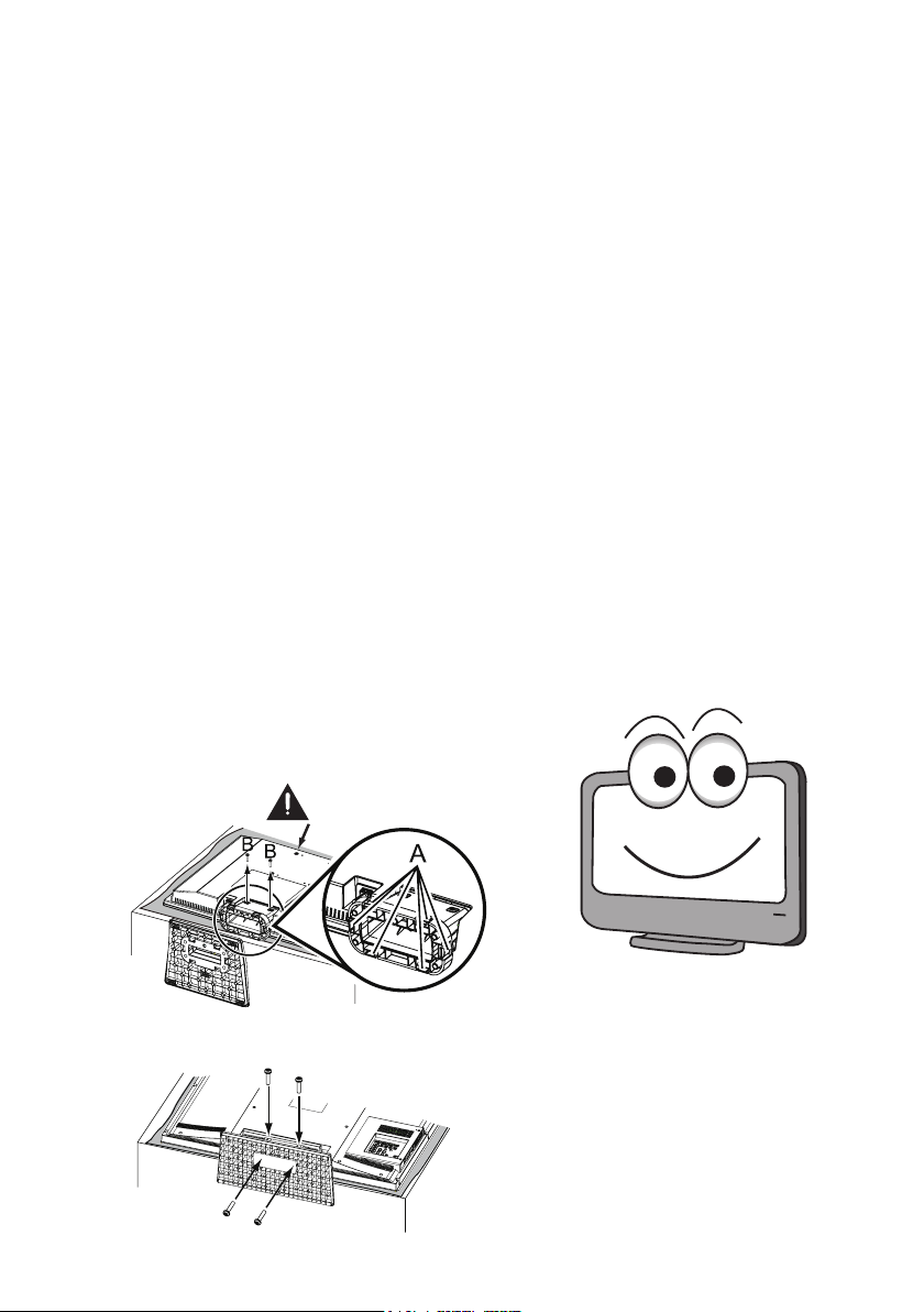
NOTE: Skip this Step if you are wall-mounting the unit.
Tool Needed: Screwdriver remove screws from stand mounting
inserts before installing stand base.
For 19”
For 26” / 32” / 42”
ATTACHING THE TV STAND
Surface
4
Hello! I'm your new Sanyo Wide-
sc r een LCD HDTV. Do n 't plug
me in just yet! Please read this
manual carefully so you can learn
about my many features, such as,
my integrated HD Tuner, PARENT
control, Digital Channels, my PC
Input and many more...

INSTALLATION
POSITIONING THE LCD HDTV
Always use a firm-flat surface when positioning
your HDTV. Do no position the unit in a
confined area. Allow adequate space for proper
ventilation.
42”
40.3
3.6
27.5
19”
26”
32”
1.4
1.8
18.2
8.6
26.3
16
31.6
12.5
17.7
13.8
19.5
22.5
6.6
2.5
8.3
3.6
3.4
25.6
1.8
NOTE: All dimensions are in inches.
WALL MOUNTING
Use the scr ews that are threaded int o the standmounting inserts on the back of your HDTV to secure it
to a wall mounting kit.
NOTE: 1. Wall Mounting kit is not supplied.
2. Wall mounting kit shall be able to sustain at least 3
times of set weight.
VESA standard interface:
19” TV 100 x 100mm ; 26” TV 100 x 200mm
32” TV 200 x 200mm ; 42” TV 200 x 400mm
Wall Mounting Inserts
Mounting screws measurements:
19” TV
M4 Diameter, Length - 13mm (min.); 16mm (max.)
26” / 32” / 42” TV
M6 Diameter, Length - 13mm (min.); 16mm (max.)
19.9
(OPTIONAL)
9.9
Wall
(65mm)
•
for 19”
(60mm)
•
for 26” / 32” / 42”
1.8
20.7
16
8.3
5

GETTING STARTED
Install supplied batteries in the Remote.
1無
ECAUTIONS
R
Do not use rechargeables together
with dry cells, other types,
mixed new and old, or batteries with
different charge levels.
Do not expose the Remote or
batteries to moisture or heat or such as sunshine, fire,
or the like.
Match the “+” and “-” signs on the batteries with marks
inside the Remote Control.
Please recycle used up rechargeable batteries.
Antenna Connection for off-air signals.
2無
ANALOG/DIGITAL
ANTENNA
OR
CABLE
ANTENNA IN
THE TUNER IN THIS HDTV CAN RECEIVE:
Digital and Analog off-air signals from an antenna.
a.
Analog or Clear QAM cable channels from a direct
b.
Cable TV connection.
NOTES:
You must use the on-screen MENU to Search for
Clear QAM Cable channels. (see page 13)
For the best picture, connect your Cable box or
Satellite receiver to HDMI1, 2, 3 or component
(VIDEO3) jacks.
This HDTV can receive ANY unscrambled RF
signal being broadcast.
OR
6
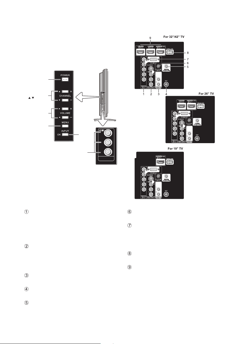
GETTING STARTED-CONTROLS AND JACKS
LEFT-SIDE
PANEL
Power
key
Channel
keys
Volume
_
+keys
Menu
key
Input
key
Video 2
input keys
VIDE O
L
R
VIDE O 2
INPU T
BACK-SIDE
PANEL
Component Video Input VIDEO3 (YPbPr), PAGE
9 - Connect digital video equipment to the Video
Green (Y), Blue (Pb), Red (Pr) jacks, and matching
Audio White (L) and Red (R) jacks. These jacks
will automatically detect the type of sign al being
received.
S-Video Input (VIDEO1) , PAGE 9 - To enhance
video detail use the S-Video jack instead of the
Video jack, if available on your external equipment.
(An S-Video connection will override a connection to
the Video1 input jack.)
Stereo Audio Out (L/R) Jacks, PAGE 11 - Connect
stereo audio equipment to these jacks.
Analog / Digital Antenna Input, PAGE 6 - Connect
an RF antenna or Analog Cable system to this jack.
Digital Audio Output (Coaxial), PAGE 11 - Use a
Pho no-Type (C oaxia l) Digi tal Audio Out Cable to
connect Digital Audio Output to an advanced stereo
home theater system equipped with Dolby® Digital.
AV Input (VIDEO1 or VIDEO2), PAGE 9 - Connect
analog video equipment here.
PC Input (1 5-Pin Moni to r and Mi ni STEREO
AUDIO), PAGE 12 - Connect computer and audio
outputs to these terminals.
MONITOR RGB (D-SUB)
•
AUDIO R/L (Stereo Mini Jack)
•
Se rv ic e por t - Fo r ser vi ce us e onl y, Used for
updating the television’s firmware.
HDM I Inpu t (INP U T1, IN PUT 2 or I N PU T 3 ),
PAGE 11 - An all digital AV interface that accepts
uncompressed video signals for the very best picture
possible. HDMI supports HDCP copy protection ,
allow in g transm is sion of co py-prot ec ted digi ta l
content. The signal can also include Dolby® Digital
or PCM audio, when available.
7

REMOTE CONTROL OPERATION
MUTE Key - Press to mute or restore the sound.
Number Keys - Press number keys to select a
channel.
Example: Press 6 then OK key to select analog
channel A6. Press 6 then 1-- key to select digital
channel D6.
INPUT Key - Press to select the source to view: TV,
VIDEO1, VIDEO2, YPbPr, HDMI1, HDMI2, HDMI3,
or PC Input.
SPORTS Key - Press to choose between options
Football, Winter Sports, Marine Sports, Indoor
Sports, and Off in turn.(See page 13)
ECO Key - Press to Energy saving mode between
options Off, ECO1, ECO2, and ECO3 in turn.
Volume Keys - Press VOL - + to decrease or
increase the audio volume.
PIX SHAPE Key - Press to choose between options
Standard, WaterGlass, Zoom1, Full and Zoom2.
Available options depend on the signal and the
broadcast’s aspect ratio.
AUD IO Key - P ress to sel ect the desire d audio
mode, if available.
MENU - Press to display on-screen menu.
CURSOR ▲ (up) ▼ (down) keys - Press these
keys to move the cursor up and down.
CURSOR ◄ (left)►(right) keys - Press these
keys to move the cursor left and right.
OK key - Press to select an option from the menu
system, when required.
EXIT key - Press to exit from the menu.
1-- Key - Press number key then press this key to
select TV digital channel.
GUIDE Key - Press to show window with the guide
information displayed on your HDTV screen (digital
channel only).
INFO Key - Press to display Channel Banner
information.
Digital Banner may contain: Channel Number,
CC State, Channel Title, Video Resolution, Video
Ratio, Signal Strength, Digital Sound information &
Program Rating.
Analog Banner may contain: Channel Number,
CC State, Channel Title, Video Resolution, Analog
Sound information, & Program Rating.
RECALL Key - Press to switch to last channel or
input selected.
Channel Up / Down (CH+, _) Keys - Press to switch
to last / next active channel.
RESET Key -
If execute RESET function, the TV will clear all
customized settings.
NOTE : The Channel Scan Memory database will be reset
SLEEP Key - Press Press this key to switch Off
Timer between Off, 30 min, 60 min, 90 min, 120 min,
150 min and 180 min options.
NOTE : The Off Timer cancels if th eTV is turned off or if a
CAPTION Key - Press this key to switch CC mode
between
options. Digital Captions can be changed using the
menu settings.
Press this key to display RESET menu.
to default (all analog channel enabled), please
execute Channel Scan after RESET.
power failure occurs.
“Off”, “CC
Display” and “Muted=On”
8

GETTING STARTED-CONNECTIONS
INPUT 1
DVI
INPUT 2INPUT 3
VIDEO 3
INPUT
VIDEO1 INPUT
PC INPU T
PC
INPUT
AUDIO
S-VID EO
L
R
L
R
Pr
Pb
Y
VIDEO
L
R
AUDIO OU T
DIGITAL
AUDIO O UT
ANTANT
INPUT 1
DVI
INPUT 2INPUT 3
VIDEO 3
INPUT
VIDEO1 INPUT
PC INPU T
PC
INPUT
AUDIO
S-VID EO
L
R
L
R
Pr
Pb
Y
VIDEO
L
R
AUDIO OU T
DIGITAL
AUDIO O UT
ANTANT
Analog Signal Connections - VIDEO1 or VIDEO2
3無
(optional)
Connect an analog device, such as, an Analog
Cable Box, Satellite Receiver, or VCR
Composite connectors are included on your
new HDTV to provide continued compatibility with
older analog devices, such as a VCR. The S-Video
connector will provide the best analog resolution. If
you have an S-Video connector on your old analog
equipment, you should use it instead of the standard
video connector. (Cables are not supplied)
Connect an AV cable to the VIDEO1 or VIDEO2
1無
jack on the HDTV and to your analog AV
equipment, as shown. Match the connector colors
to jack colors.
Press the INPUT key to step through the signal
2無
inputs to select
Y
Pb
Pr
R
L
VIDEO 3
INPUT
Video1 or Video2
INPU T1
INPU T2INPU T3
PC INP UT
S-VI DEO
PC
AUDIO
INPUT
VIDEO
L
L
R
R
AUDIO O UT
VIDEO1 INPUT
DVI
DIGITA L
AUDIO O UT
ANT
.
ANT
Digital Signal Connections - Video3 (YPbPr)
4無
Connect Digital devices, such as, an HD Cable
Box, HD Satellite Receiver, DVD Player, and Game
System
The Component jacks on this HDTV will accept
HDTV, EDTV, and SDTV video signals, making
Component a great choice when connecting your
compatible external devices.
Connect a COMPONENT cable to a set of
1無
Green, Blue, and Red video jacks Video3
(YPbPr) on the HDTV and to your digital device,
as shown. (Cable is not supplied)
Connect an AUDIO cable to the matching set of
2無
White and Red audio jacks, as shown. (Cable is
not supplied)
Press the INPUT key to step through the signal
3無
inputs to select Video3 (YPbPr).
DVD PLAYER
SARELLITE
RECEIVER
ANALOG DEVICE
9
 Loading...