

Sanyo LB1669 Specifications
Ordering number: ENN3513C
10
6
LB1669
2-Phase Unipolar Brushless Motor Driver
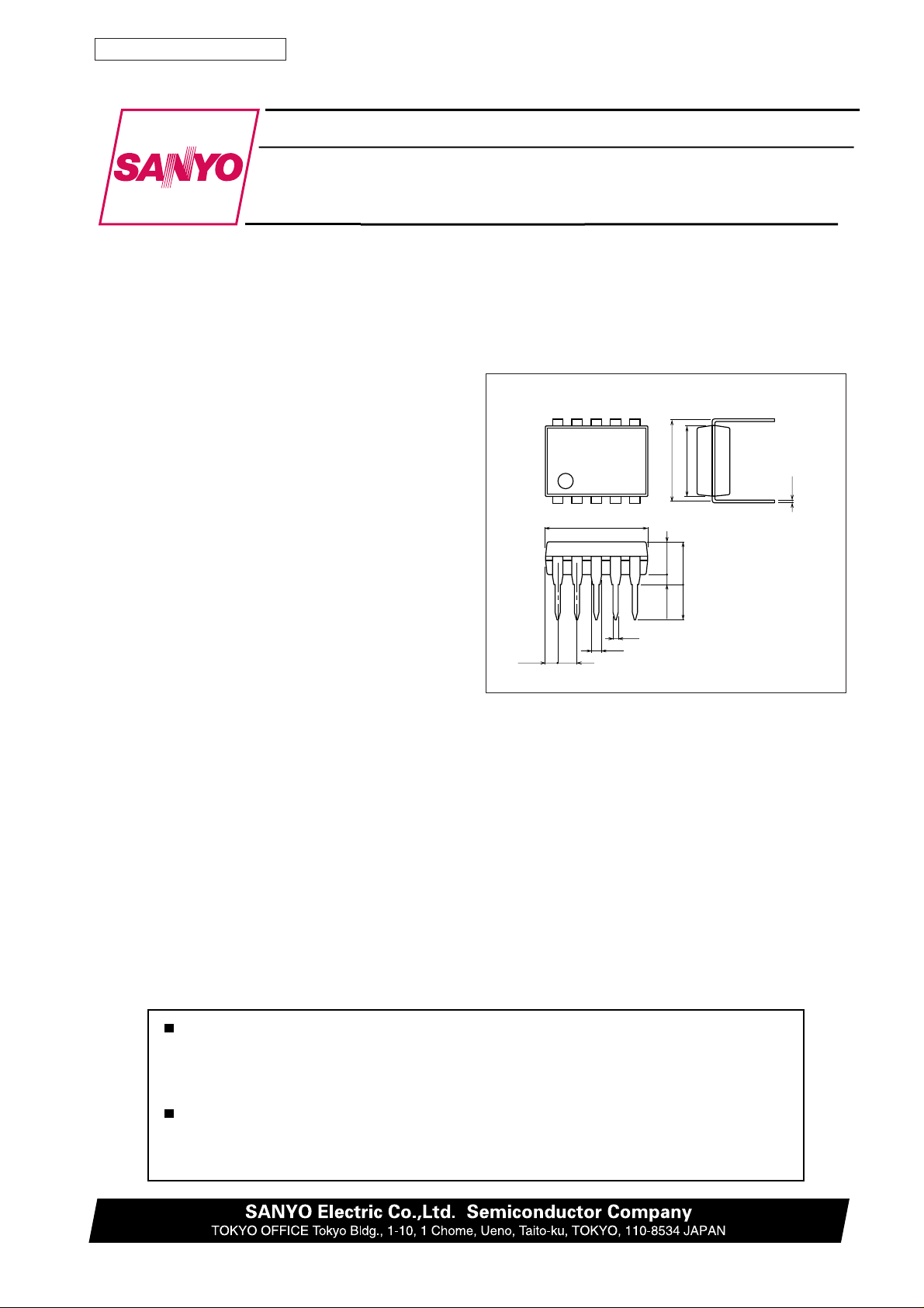
Overview Package Dimensions
The LB1669 is a 2-phase uniploar brushless motor driver,
which allows motor lock protection and automatic recovery
circuits to be implemented with few extenal components.
unit : mm
3098B-DIP10S
[LB1669]
Features and Functions
6.4
0.48
7.62
5
3.0
3.9max
3.2
0.51min
• Hall element direct connection possible
• Output transistor with 1.5 A output current built in
• Rotation detect function (Drive mode: ‘‘L’’,
Stop mode:‘‘H’’) built in
• Motor lock protection and automatic recovery functions
built in
• Thermal shutdown circuit built in
• DIP-10S package means small mounting area.
• Pin compatible with LB1663, so can replace 12 V types.
1
1.14 1.78
9.4
0.95
Monolithic Digital IC
LB1669
0.25
SANYO : DIP10S
Any and all SANYO products described or contained herein do not have specifications that can handle
applications that require extremely high levels of reliability, such as life-support systems, aircraft’s
control systems, or other applications whose failure can be reasonably expected to result in serious
physical and/or material damage. Consult with your SANYO representative nearest you before using
any SANYO products described or contained herein in such applications.
SANYO assumes no responsibility for equipment failures that result from using products at values that
exceed, even momentarily, rated values (such as maximum ratings, operating condition ranges, or other
parameters) listed in products specifications of any and all SANYO products described or contained
herein.
82599TH(II)/D3096HA(II)/7120TA(GTPS)No.3513-1/6
No. 3513-1/6
LB1669
Specifications
Absolute Maximum Ratings at Ta = 25°C
Parameter Symbol Conditions Ratings Unit
Maximum input current ICC max t < 20 ms 200 mA
Output applied voltage V
Output current I
RD flow-in current I
RD applied voltage V
OUT
OUT
RD
RD
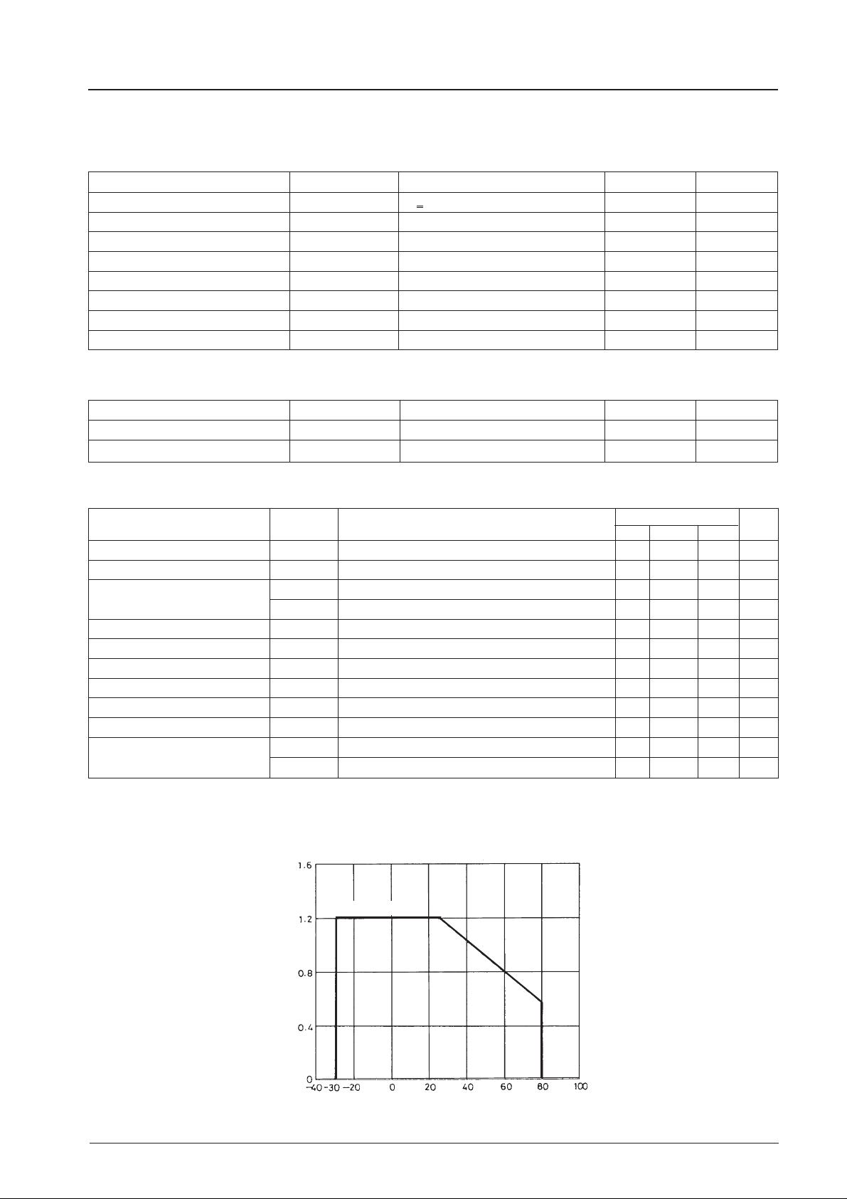
Allowable power dissipation Pd max Independent IC 1.2 W
Operating temperature Topr –30 to +80 °C
Storage temperature Tstg –55 to +125 °C
Allowable Operating Conditions at Ta = 25°C
Parameter Symbol Conditions Ratings Unit
Input current range I
Common-mode input voltage ange V
CC
ICM
–0.3 to +60 V
1.5 A
10 mA
30 V
6.0 to 5.0 mA
0 to VIN–1.5 V
Electrical Characteristics at Ta = 25°C, ICC = 10 mA
Parameter Symbol Conditions
Output withstand voltage 1 V
OR
Output withstand voltage 2 VO(sus) IO = 0.1 A 40 V
Output saturation voltage
VO sat1 IO = 0.5 A 0.95 1.2 V
VO sat2 IO = 1.0 A 1.15 1.5 V
VIN voltage V
Amp input offset voltage V
Amp input bias current I
IN
OFF
BA
I
= 7.0 mA 6.4 6.7 7.0 V
CC
RD output saturation voltage VRD (sat) IRD = 5 mA 0.1 0.2 V
C flow-out current I
C discharge current I
Comparator input threshold V
voltage
C1
C2
TH1
V
TH2
Pd max –Ta
Ratings
min typ max
60 V
–7 0 +7 mV
–250 nA
2.1 3 3.9 µA
0.31 0.44 0.59 µA
0.77 0.8VIN0.83 V
0.42 0.45VIN0.48 V
Unit
Independent IC
Allowable power dissipation, Pd max – W
Ambient temperature, Ta – °C
No. 3513-2/6
 Loading...