

SANYO LB1651D Datasheet
Ordering number: EN5437
Monolithic Digital IC
LB1651D
Dual Bidirectional Motor Driver
Overview
The LB1651D is a dual bidirectional motor driver that is
designed to drive motors directly by TTL outputs. It provides
the functions of bidirectional motor drive, brake that are
determined by two inputs and the inhibit function that brings
the output to a high impedance state.
Applications
.
Multi DC motor driver
.
Bidirectional motor driver
.
Bipolar stepping motor driver
Features
.
High output current (1 A/ch)
.
Wide operating voltage range (4.5 to 36 V)
.
Inhibit function
.
Direct drive made possible by TTL, CMOS IC
.
High noise margin
Specifications
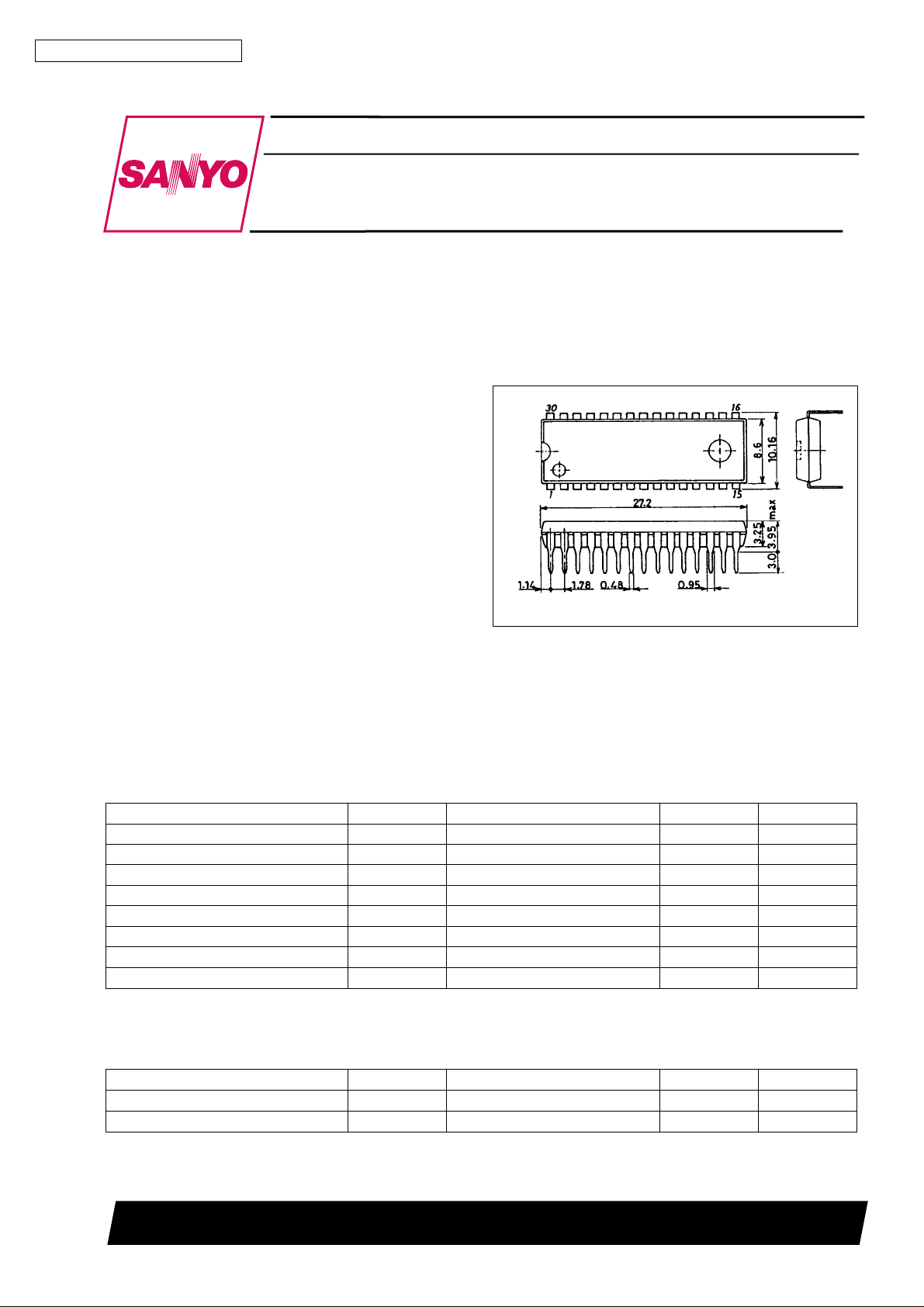
Package Dimensions
unit : mm
3196-DIP30SD
[LB1651D]
SANYO : DIP30SD
Absolute Maximum Ratings at Ta = 25°C
Parameter Symbol Conditions Ratings Unit
Maximum supply voltage V
Logic supply voltage V
Input voltage V
Inhibit voltage V
Peak output current I
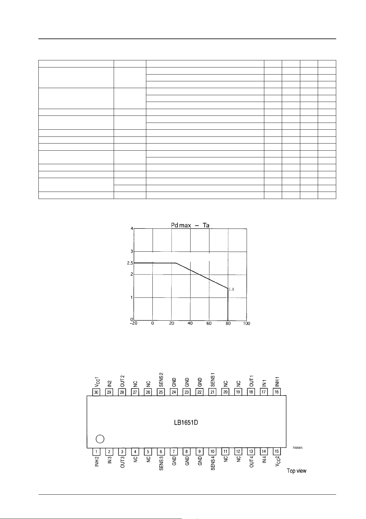
Allowable power dissipation Pd max * With specified board 2.5 W
Operating temperature Topr –20 to +80 °C
Storage temperature Tstg –40 to +150 °C
* Specified board: 114 × 76 × 1.6 mm
3
136V
CC
236V
CC
IN
inh
OUT
1 ms non-repetitive 2 A
7V
7V
Allowable Operating Conditions at Ta = 25°C
Parameter Symbol Conditions Rating Unit
Supply voltage V
Logic supply voltage V
1 4.5 to 36 V
CC
2 4.5 to 36 V
CC
SANYO Electric Co.,Ltd. Semiconductor Bussiness Headquarters
TOKYO OFFICE Tokyo Bldg., 1-10, 1 Chome, Ueno, Taito-ku, TOKYO, 110 JAPAN
43096HA(II) No.5437-1/4
LB1651D
Electrical Characteristics at Ta = 25°C, VCC1=24V,VCC2=5V
Parameter Symbol Conditions min typ max Unit
=L,IO=0,Vinh=H 1.5 mA
V
Supply current
(Per channel)
Logic supply current I
Low-level input voltage V
High-Level Input Voltage V
Low-level input current I
High-level input current I
1
I
CC
2
CC
IL
IH
IL
IH
Low-level inhibit voltage VinhL –0.3 +1.5 V
High-level inhibit voltage VinhH
Low-level inhibit current IinhL –100 –30 µA
High-level inhibit current IinhH ±10 µA
V
(sat)H IO= –1 A 1.4 1.8 V
Saturation voltage
Sensing voltage V
CE
V
(sat)L IO= 1 A 1.2 1.8 V
CE
SENS
IN
V
=H,IO=0,Vinh=H 6 mA
IN
Vinh=L 1 mA
=L,IO= 0, Vinh = H 44 60 mA
V
IN
V
=H,IO=0,Vinh=H 22 mA
IN
Vinh = L 24 mA
–0.3 +1.5 V
VCC2 % 7 V 2.3 VCC2V
V
2>7V 2.3 7 V
CC
VIN=L ±10 µA
VIN= H − 0.3 V 30 100 µA
V
2 % 7 V 2.3 VCC2V
CC
V
2>7V 2.3 7 V
CC
2V
Pin Assignment
With specified board (114 × 76 × 1.6 mm3)
Allowable power dissipation, Pd max − W
Ambient temperature, Ta − °C
No.5437-2/4
 Loading...