

SANYO LA6538T Datasheet
Ordering number : ENN6518
83000RM (OT) No. 6518-1/6
Overview
The LA6538T is optimal for use as a fan motor driver in
equipment, such as notebook personal computers and
electronic game units, that requires miniaturization and
low noise levels. This device achieves highly efficient
single-phase bipolar fan motor drive by providing a low
saturation voltage BTL output.
Functions and Features
• BTL output single-phase full-wave linear drive (gain
resistance: 180 to 500 kΩ, 360×)
— Since this device generates no switching noise, it is
optimal for fan drive in audio equipment, electronic
games, and notebook personal computers.
• Supports low-voltage operation and features a wide
usable voltage range (VCC= 2.5 to 9.5 V).
• Low saturation voltage output (Upper side + lower side
saturation voltage: VOsat(total) = 0.2 V (typ),
IO= 100 mA)
— This device achieves a high coil efficiency for low
current drain, and generates minimal heat in the IC
itself.
• Constant-voltage Hall bias output.
— The Hall element is regulated at 2.1 V, and the
device provides a stable Hall output with excellent
temperature characteristics.
• FG output
— The LA6538T provides a speed detection output (an
open-collector output).
• Built-in thermal protection circuit
— This circuit limits the drive current to prevent
damage to or destruction of the IC when the IC chip
temperature exceeds 180°C due to excessive output
current caused by load shorting or other problem.
• Ultraminiature package
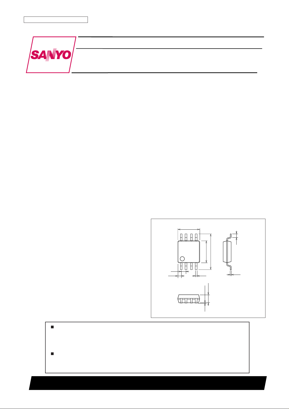
(MSOP-8: 3.0 × 4.9 × 0.93 mm3)
— Allows the circuit board to be miniaturized and a
large heat sink to be used.
Reference materials:
T package (MSOP-8) series fan motor drivers
LB1964T: 3 and 5 V operation, low saturation voltage
switching single-phase bipolar drive, FG output
LB11963T: 5 and 12 V operation, switching single-
phase bipolar drive, restart circuit, lock detection, 1/2
FG output
LB11964T: 5 and 12 V operation, switching singlephase bipolar drive, restart circuit, lock detection, FG
output
Package Dimensions
unit: mm
3245-MSOP8
4.9
3.0
0.65
3.0
(0.5)
(0.85)
0.5
0.25
14
85
0.25
0.08
1.1max
SANYO: MSOP8
[LA6538T]
LA6538T
SANYO Electric Co.,Ltd. Semiconductor Company
TOKYO OFFICE Tokyo Bldg., 1-10, 1 Chome, Ueno, Taito-ku, TOKYO, 110-8534 JAPAN
Single-Phase Full-Wave Fan Motor Driver
Monolithic Linear IC
Any and all SANYO products described or contained herein do not have specifications that can handle
applications that require extremely high levels of reliability, such as life-support systems, aircraft’s
control systems, or other applications whose failure can be reasonably expected to result in serious
physical and/or material damage. Consult with your SANYO representative nearest you before using
any SANYO products described or contained herein in such applications.
SANYO assumes no responsibility for equipment failures that result from using products at values that
exceed, even momentarily, rated values (such as maximum ratings, operating condition ranges, or other
parameters) listed in products specifications of any and all SANYO products described or contained
herein.
No. 6518-2/6
LA6538T
Parameter Symbol Conditions Ratings Unit
Maximum supply voltage V
CC
max 10 V
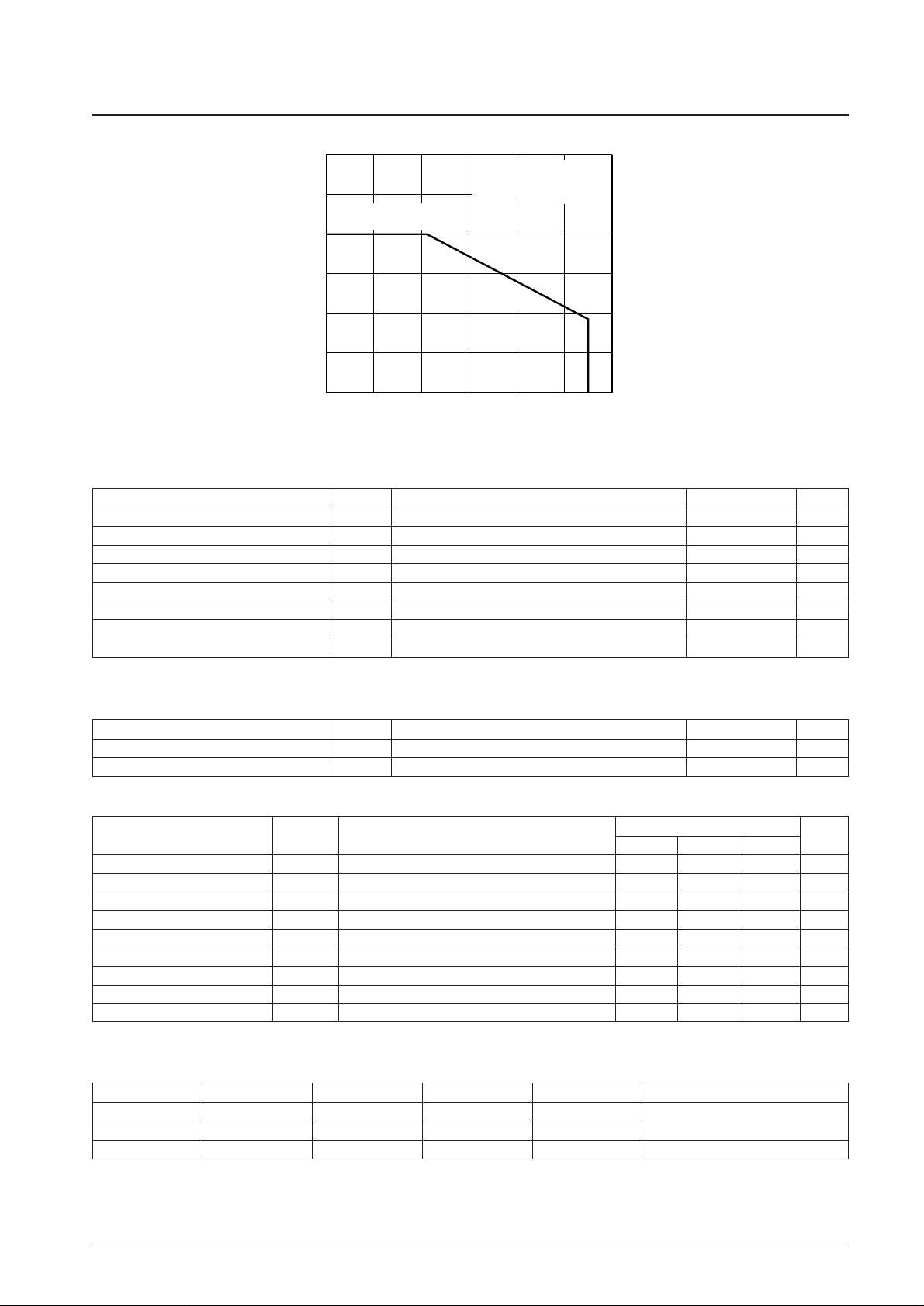
Allowable power dissipation Pd max Mounted on the specified printed circuit board* 400 mW
OUT pin output current I
OUT
max 0.3 A
OUT pin output voltage handling V
OUT
max 9.5 V
FG output voltage handling V
FG
max 10 V
FG output current I
FG
max 5mA
Operating temperature Topr –20 to +90 °C
Storage temperature Tstg –55 to +150 °C
Note: * Specified printed circuit board: 20.0 ×10.0 × 0.8 mm3paper phenolic board, wiring density: 20%.
Specifications
Maximum Ratings at Ta = 25°C
Parameter Symbol Conditions Ratings Unit
Supply voltage V
CC
2.5 to 9.5 V
Hall input common-mode input voltage range V
ICM
0.9 to VCC– 1 V
Recommended Operating Conditions at Ta = 25°C
ILA00211
Pd max — Ta
0
600
500
300
400
100
200
192
80 1000--20 20 40 60
Allowable power dissipation, Pdmax — mW
Ambient temperature, Ta — °C
Mounted on the specified
printed circuit board
Specified printed circuit board:
20.0 × 10.0 × 0.8 mm
3
Paper phenolic board
Parameter Symbol Conditions
Ratings
Unit
min typ max
Circuit current I
CC
IN–= 2.6 V, IN+= 2.4 V, RL= ∞ 10 15 mA
OUT pin output low-level voltage V
O
LIO= 100 mA 0.1 0.2 V
OUT pin output high-level voltage V
O
HIO= 100 mA 0.1 0.2 V
Hall bias voltage V
HB
RH = 360 Ω + 91 Ω 1.9 2.1 2.3 V
Hall amplifier gain VG 47 50 53 dB
Hall amplifier input resistance V
INR
400 500 620 Ω
FG output low-level voltage V
FG
IFG= 3 mA 0.2 0.3 V
FG output leakage current I
FGL
VFG= 7 V 30 µA
Thermal protection circuit T-TSD Design guarantee* 150 180 200 °C
Electrical Characteristics at Ta = 25°C, VCC= 5 V
Note: * Design guarantee: Indicates a design target value. These parameters are not tested in the independent IC.
Truth Table
IN
–
IN
+
OUT1 OUT2 FG Mode
HLHLL
Motor operating
LHLHoff
— — off off — Thermal protection activated
 Loading...