

SANYO LA6537M Datasheet
Ordering number: EN 5231
Monolithic Linear IC
LA6537M
4-channel Bridge Driver
for CD and CD-ROMs
Overview
The LA6537M is a 4-channel bridge (BTL) driver which was
developed for compact discs and CD-ROMs.
Features and Functions
.
4-channel bridge (BTL) power amplifier.
.
IOmax 700 mA.
.
With mute circuit (Amp 3, Amp 4).
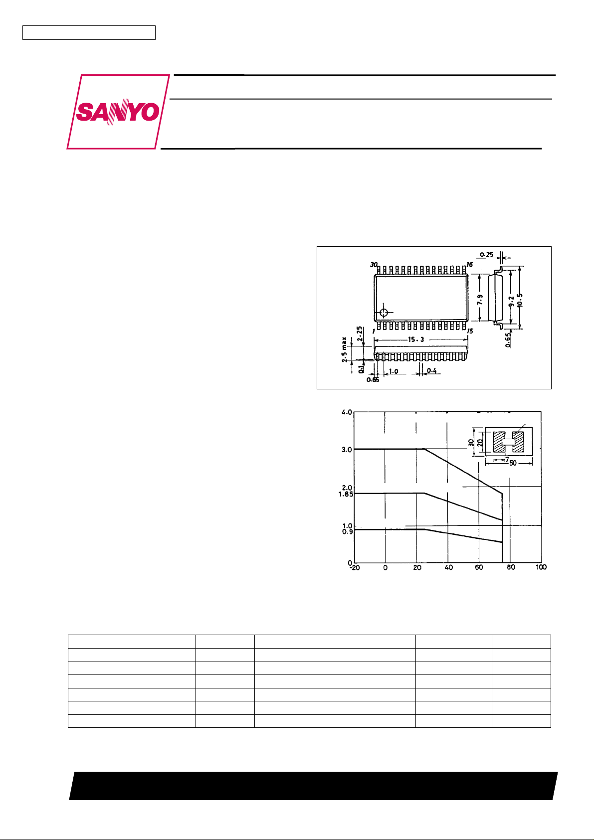
Package Dimensions
unit : mm
3073A-MFP30SLF
[LA6537M]
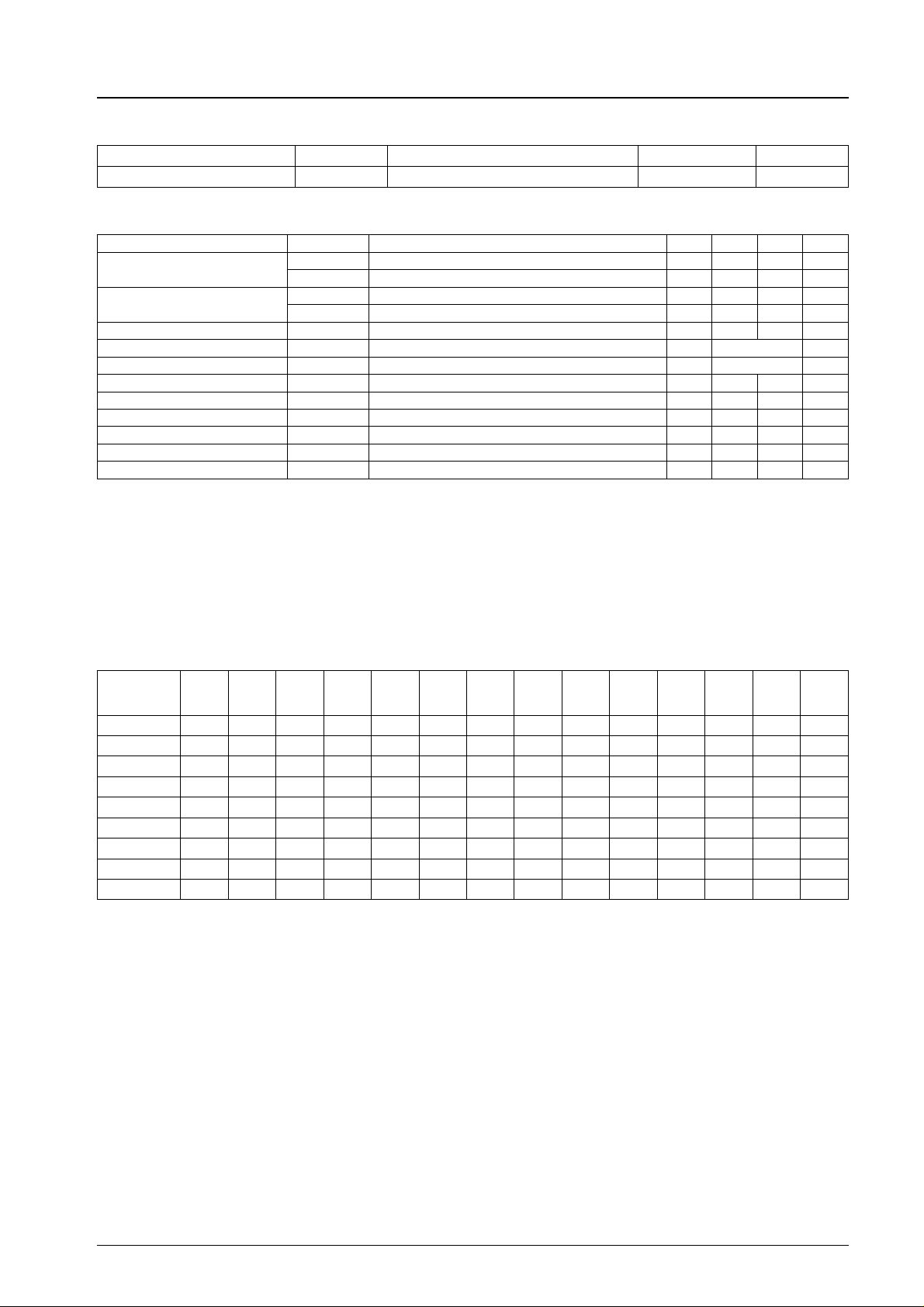
Pd max — Ta
PCB (glass epoxy resin) Cu foil
Steel substrate (t=1mm)
reference value
SANYO : MFP30SLF
Thickness 1.5 mm
Mounted on PCB (glass epoxy)
Independent IC
Allowable power dissipation, Pd max — W
Ambient temperature, Ta —°C
Specifications
Maximum Ratings atTa=25°C
Parameter Symbol Conditions Ratings Unit
Maximum supply voltage V
Maximum input voltage V
Mute pin voltage V
Allowable power dissipation Pd max * Mounted on PCB shown below 0.9 W
Operating temperature Topr –20 to +75
Storage temperature Tstg –55 to +150
* PCB (20 × 30 × 1.5 mm glass epoxy resin)
max 14 V
CC
INB
M
13 V
13 V
C
°
C
°
SANYO Electric Co.,Ltd. Semiconductor Bussiness Headquarters
TOKYO OFFICE Tokyo Bldg., 1-10, 1 Chome, Ueno, Taito-ku, TOKYO, 110 JAPAN
92995HA(II) No.5231-1/4
LA6537M
Operating Conditions atTa=25°C
Parameter Symbol Conditions Ratings Unit
Recommended supply voltage V
Electrical Characteristics atTa=25°C, VCC= 7.5 V
CC
4to13 V
Parameter Symbol
No-load current drain
Output offset voltage
V
V
Input bias current I
Buffer input voltage range V
Input voltage range V
Output source voltage V
Output sink voltage V
I
1 Note 1 20 40 60 mA
CC
I
2 Note 2 26 60 mA
CC
1 Note 3, amplifiers1—2,7—8 –50 +50 mV
OF
2 Note 3, ampifiers3—4,5—6 –50 +50 mV
OF
B
BIN
IN
1 Note 4, RL= 8.0 Ω 5.0 5.6 V
O
2 Note 5, RL= 8.0 Ω 1.8 2.4 V
O
Conditions
min typ max Unit
100 500 nA
1.5 VCC−1.5 V
1.0 VCC−1.5 V
Closed-circuit voltage gain VG Bridge amplifier 12 dB
Slew rate SR 0.15 V/µs
Mute on voltage V
Mute pin inflow current I
M
Note 6 2 V
M
Note 6 60 µA
Notes:
1. Mute off and buffer in assume 1/2 V
CC
V.
2. Mute off and buffer in assume 0.5 V.
3. Represents the interoutput difference.
4. Voltage relative to ground (source) when an 8 Ω load is connected between bridge amplifier outputs.
5. Voltage relative to ground (sink) when an 8 Ω load is connected between bridge amplifier outputs.
6. Muting is activated when high, and the amplifier outputs 3 and 4 are off.
Test Method
SW No.
Item
1
I
CC
2
I
CC
1,2
V
OF
I
B
1
V
O
2
V
O
V
M
I
M
VG b ON ON OFF OFF b b OFF ON OFF OFF b ON ON
1234567891011121314
a ON ON OFF OFF b b OFF ON OFF OFF b OFF OFF
a ON ON OFF OFF b b OFF ON OFF OFF a OFF OFF
b ON ON OFF OFF b b OFF ON OFF OFF b OFF OFF
b OFF OFF ON OFF a a ON OFF OFF OFF b OFF OFF
b OFF ON OFF ON b a OFF OFF OFF ON b OFF OFF
b OFF OFF OFF OFF a b OFF ON ON ON b OFF OFF
b ON ON OFF OFF b b OFF ON OFF OFF b OFF OFF
b ON ON OFF OFF b b OFF ON OFF OFF b OFF OFF
1. For ICC1 and 2, measure the inflow current on the VCCpin.
2. For V
1 and 2, measure the voltage between pins 3 and 4 (amplifiers 1 and 2), pins 27 and 28 (amplifiers 7 and 8), pins 12
OF
and 13 (amplifiers 3 and 4), and pins 18 and 19 (amplifiers 5 and 6).
3. For I
4. For V
5. V
6. I
, measure the voltage across the 100 kΩ resistor (IB= V/100 kΩ).
B
1 and 2, measure each output voltage at input voltages 1.75 V and 5.75 V, respectively.
O
is the mute pin (pin 7) voltage when the output goes off.
M
is the mute pin (pin 7) inflow current when the output goes off.
M
7. For VG, measure the voltage between pins 3 and 4 (amplifiers 1 and 2), pins 27 and 28 (amplifiers 7 and 8), pins 12 and 13
(amplifiers 3 and 4), and pins 18 and 19 (amplifiers 5 and 6) atf=1kHz, and use the following formula:
VG = 20 log V
O/V1
dB.
No.5231-2/4
 Loading...