

SANYO LA6537 Datasheet
Ordering number: EN 5822
Monolithic Linear IC
LA6537
4-channel Bridge Driver
for CD and CD-ROMs
Overview
The LA6537 is a 4-channel bridge (BTL) driver which was
developed for compact discs and CD-ROMs.
Features and Functions
.
4-channel bridge (BTL) power amplifier.
.
IOmax 700 mA.
.
With mute circuit (Amp 3, Amp 4).
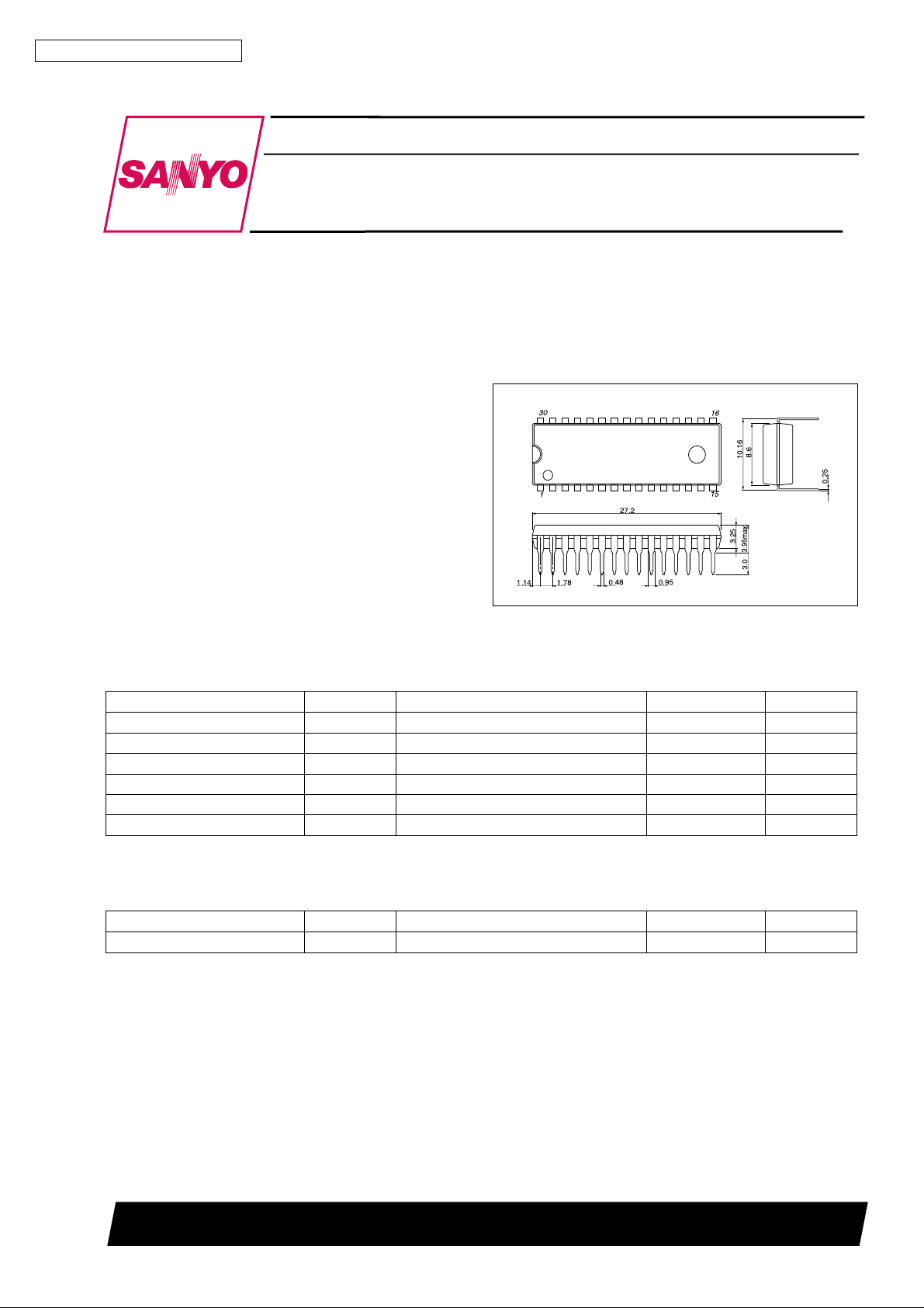
Package Dimensions
unit : mm
3196-DIP30SLF
[LA6537]
SANYO : DIP30SLF
Specifications
Maximum Ratings atTa=25°C
Parameter Symbol Conditions Ratings Unit
Maximum supply voltage V
Allowable power dissipation Pd max * Mounted on PCB shown below 2.5 W
Maximum input voltage V
Mute pin voltage V
Operating temperature Topr –20 to +75
Storage temperature Tstg –55 to +150
max 14 V
CC
INB
MUTE
13 V
13 V
C
°
C
°
* PCB (114.3 × 76.2 × 1.5 mm glass epoxy resin)
Recommended Operating Conditions atTa=25°C
Parameter Symbol Conditions Ratings Unit
Supply voltage V
CC
4to13 V
SANYO Electric Co.,Ltd. Semiconductor Bussiness Headquarters
TOKYO OFFICE Tokyo Bldg., 1-10, 1 Chome, Ueno, Taito-ku, TOKYO, 110 JAPAN
13098HA(II) No.5822-1/4
LA6537
Electrical Characteristics atTa=25°C, VCC= 7.5 V
Parameter Symbol
No-load current drain
Output offset voltage
V
V
Input bias current I
Buffer input voltage range V
Input voltage range V
Output source voltage V
Output sink voltage V
I
1 Note 1 20 40 60 mA
CC
I
2 Note 2 26 60 mA
CC
1 Note 3, amplifiers 1 to 2, 7 to 8 –50 +50 mV
OF
2 Note 3, ampifiers 3 ro 4, 5 to 6 –50 +50 mV
OF
B
BIN
IN
1 Note 4, RL= 8.0 Ω 5.0 5.6 V
O
2 Note 5, RL= 8.0 Ω 1.8 2.4 V
O
Conditions
min typ max Unit
100 500 nA
1.5 VCC−1.5 V
1.0 VCC−1.5 V
Closed-circuit voltage gain VG Bridge amplifier 12 dB
Slew rate SR 0.15 V/µs
Mute on voltage V
Mute on current I
MUTE
MUTE
2V
60 µA
Notes:
1. Mute off and buffer in assume 0.5 V.
2. Mute off and buffer in assume 1/2 V
CC
V.
3. Represents the interoutput difference.
4. Voltage relative to ground (source) when an 8 Ω load is connected between bridge amplifier outputs.
5. Voltage relative to ground (sink) when an 8 Ω load is connected between bridge amplifier outputs.
Thus, muting is activated when high, and the amplifier outputs 5 and 6 are off.
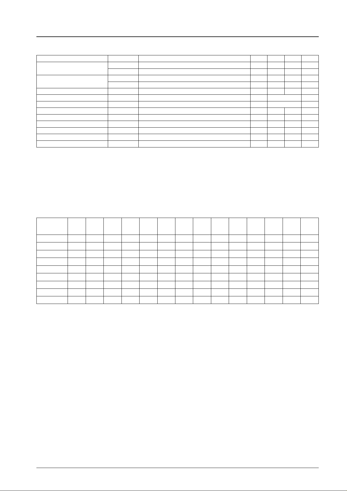
Test Method
SW No.
Item
1
I
CC
2
I
CC
1,2
V
OF
I
B
1
V
O
2
V
O
V
MUTE
I
MUTE
VG b ON ON OFF OFF b b OFF ON OFF OFF b ON ON
1234567891011121314
a ON ON OFF OFF b b OFF ON OFF OFF b OFF OFF
a ON ON OFF OFF b b OFF ON OFF OFF a OFF OFF
b ON ON OFF OFF b b OFF ON OFF OFF b OFF OFF
b OFF OFF ON OFF a a ON OFF OFF OFF b OFF OFF
b OFF ON OFF ON b a OFF OFF OFF ON b OFF OFF
b OFF OFF OFF OFF a b OFF ON ON ON b OFF OFF
b ON ON OFF OFF b b OFF ON OFF OFF b OFF OFF
b ON ON OFF OFF b b OFF ON OFF OFF b OFF OFF
1. For ICC1 and 2, measure the inflow current on the VCCpin.
2. For V
1 and 2, measure the voltage between pins 5 and 6 (amplifiers 1 and 2), pins 25 and 26 (amplifiers 7 and 8), pins 10
OF
and 11 (amplifiers 3 and 4), and pins 20 and 21 (amplifiers 5 and 6).
3. For I
4. For V
5. V
6. I
, measure the voltage across the 100 kΩ resistor (IB= V/100 kΩ).
B
1 and 2, measure each output voltage at input voltages 1.75 V and 5.75 V, respectively.
O
is the mute pin (pin 15) voltage when the output goes off.
MUTE
is the mute pin (pin 15) inflow current when the output goes off.
MUTE
7. For VG, measure the voltage between pins 5 and 6 (amplifiers 1 and 2), pins 25 and 26 (amplifiers 7 and 8), pins 10 and 11
(amplifiers 3 and 4), and pins 20 and 21 (amplifiers 5 and 6) atf=1kHz, and use the following formula:
VG = 20 log V
O/VIN
dB.
No.5822-2/4
 Loading...