

SANYO LA6529M Datasheet
Monolithic Linear IC
No. 5638
CD-ROM Drive Three-Channel Bridge (BTL) Driver
Overview
The LA6529M is a three-channel bridge (BTL) driver for
CD-ROM drives.
Functions and Features
• Three bridge-tied load (BTL) power amplifier channels
•IOmax: 1 A
• Muting circuit
• Thermal shutdown circuit
LA6529M
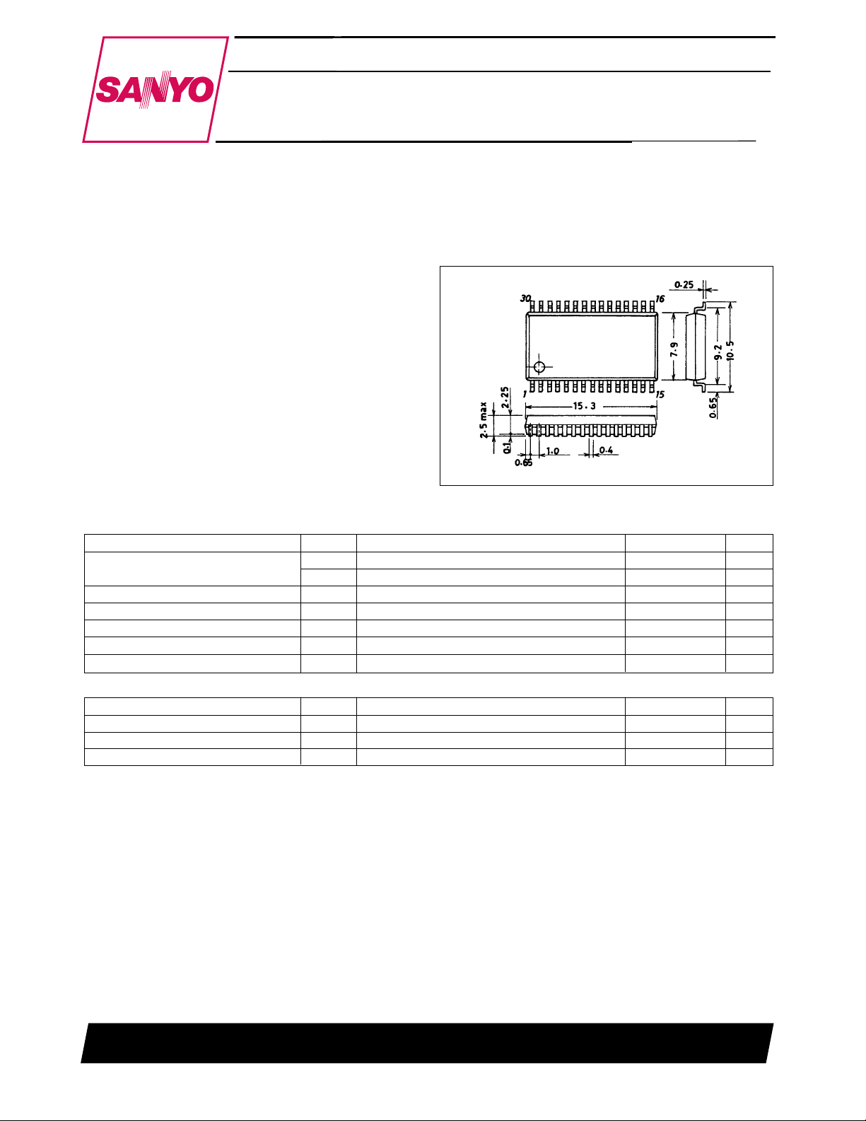
Package Dimension
unit: mm
3073A-MFP30SLF
[LA6529M]
SANYO: MFP30SLF
Specifications
Maximum Ratings at Ta = 25°C
Parameter Symbol Conditions Ratings Unit
V
max 14 V
Supply voltage
Maximum input voltage V
Mute pin voltage V
Allowable power dissipation Pd max 0.9 W
Operating temperature Topr –20 to +75 °C
Storage temperature Tstg –55 to +150 °C
Operating Conditions at Ta = 25°C
Parameter Symbol Conditions Ratings Unit
Operating voltage 1 V
Operating voltage 2-1 V
Operating voltage 2-2 V
Note: VCC> VS1, VS2
CC
V
max Maximum rating for VS1 and VS214V
S
For the VIN1 through VIN3 input pins 13 V
IN
Mute
CC
1 The operating voltage for CH-U 4 to 13 V
S
2 The operating voltage for CH-V and CH-W 4 to 13 V
S
13 V
4 to 13 V
SANYO Electric Co.,Ltd. Semiconductor Bussiness Headquarters
TOKYO OFFICE Tokyo Bldg., 1-10, 1 Chome, Ueno, Taito-ku, TOKYO, 110 JAPAN
43097HA(OT) No. 5638-1/4
LA6529M
Electrical Characteristics at Ta = 25°C, VCC=12 V, VS1 = VS2 = 5 V
Parameter Symbol Conditions
no-load input current drain
V
CC
1 no-load current drain
V
S
2 no-load current drain
V
S
Output offset voltage V
1 to VOF3
OF
Input voltage range V
Buffer amplifier 1 output voltage V
Buffer amplifier 2 output voltage V
BUFFER
BUFFER
Output voltage (source) V
Output voltage (sink) V
min typ max
1 All outputs on (Mute 1, 2: high *)4815mA
I
CC
I
2 All outputs off (Mute 1, 2: low) – 4 10 mA
CC
1-1 CH-U: on (Mute 1: high *)–510mA
I
S
I
1-2 CH-U: off (Mute 1: low) – – 2 mA
S
2-1 CH-V, CH-W: on (Mute 2: high *) – 10 20 mA
I
S
I
2-2 CH-V, CH-W: off (Mute 2: low) – – 4 mA
S
The potential difference between
the + and – sides for CH-U through CH-W
The voltage range for VIN1 through VIN3. 0.5 – 5 V
IN
1
The voltage difference with respect to 1/2 VS1
2
The voltage difference with respect to 1/2 VS2
1 Output high, IO= 700 mA, for + outputs 4.4 4.7 – V
O
2 Output low, IO= 700 mA, for + outputs – 0.3 0.6 V
O
Ratings
Unit
–50 – +50 mV
–50 0 +50 mV
–50 0 +50 mV
Closed loop voltage gain VG Bridge amplifier – 6 – dB
Slew rate SR – 0.15 – V/µs
Mute on voltage V
Mute on current I
MUTE
MUTE
The voltage applied to MUTE1 or MUTE2
1, 2
when the output goes on.
The MUTE1 or MUTE2 influx current when
1, 2
the output goes on.
– 1.5 2 V
–610µA
Note: * CH-U will be on when MUTE1 is high. CH-V and CH-W will be on when MUTE2 is high.
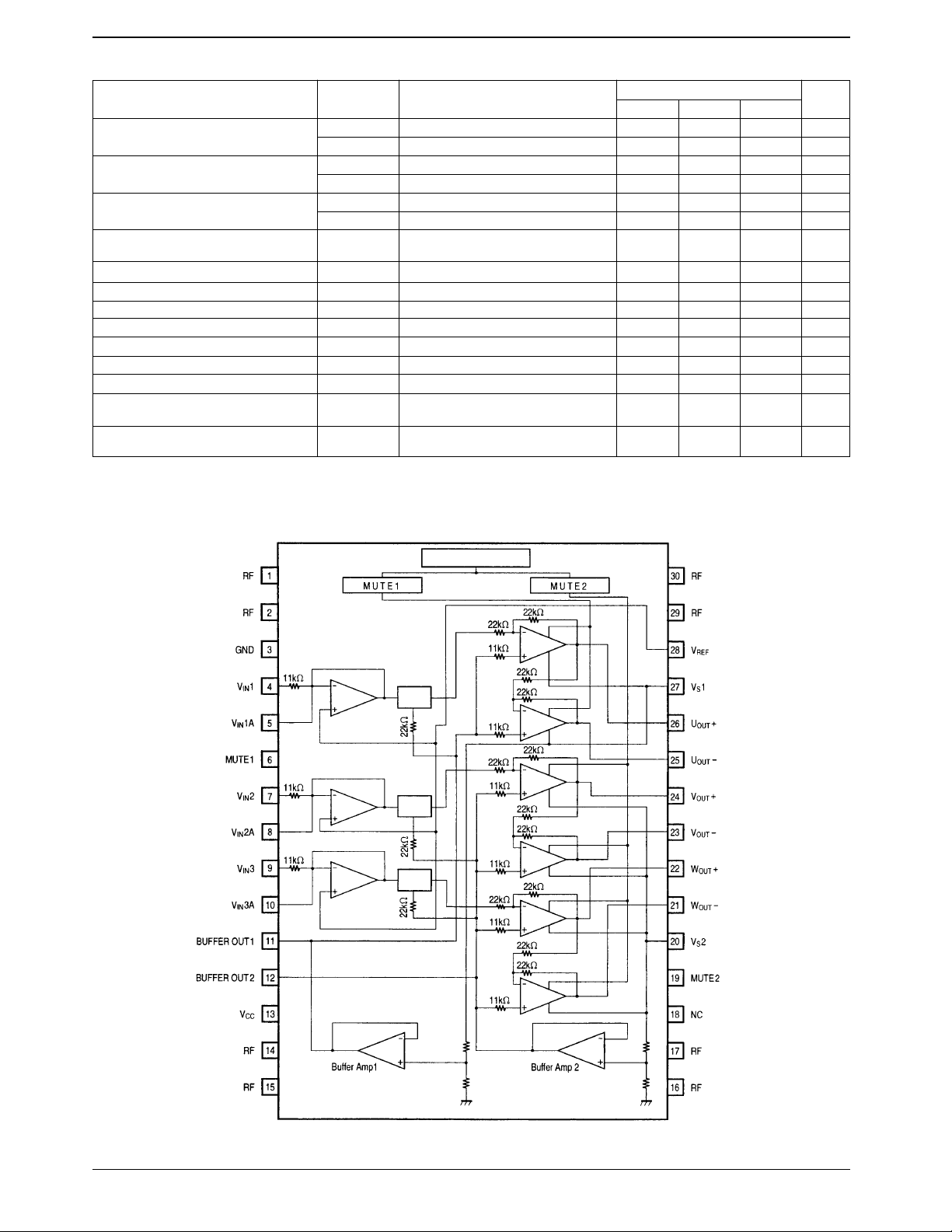
Block Diagram
Level
shifter
Level
shifter
Level
shifter
Thermal shutdown
No. 5638-2/4
 Loading...