

SANYO LA4636 Datasheet
Ordering number: ENN6985
SANYO Electric Co.,Ltd. Semiconductor Company
TOKYO OFFICE Tokyo Bldg., 1-10, 1 Chome, Ueno, Taito-ku, TOKYO, 110-8534 JAPAN
Monolithic Linear IC
LA4636
For General Audio Use
11 W 2-Channel BTL AF Power Amplifier
Overview
The LA4636 is a BTL power IC that is pin-compatible
with the LA4635A and LA4635B single-end power ICs. It
represents a new concept in devices of this type by
allowing design editing based on common circuit board pin
compatibility for products of different power ranks. The
LA4636 also incorporates several protection circuits.
Specifications
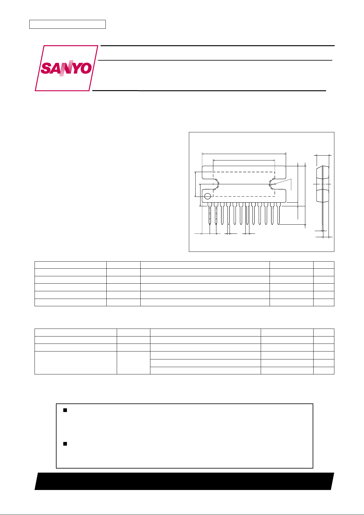
Package Dimensions
unit: mm
3049B-SIP12H
[LA4636]
26.8
(20.0)
(8.4)
7.0
(2.4)
2.0
0.5
1.0
(11.8)
(R1.7)
121
SANYO: SIP12H
1.0min
13.2max
6.0
0.4
2.0
Maximum Ratings at Ta = 25°C
Parameter Symbol Conditions Ratings Unit
Maximum supply voltage V
Maximum output current Io peak Per channel 2.5 A
Allowable power dissipation Pd max Infinite heat sink 25 W
Operating temperature Topr –20 to +75 °C
Storage temperature Tstg –40 to +150 °C
max No signal 24 V
CC
4.0
Operating Conditions at Ta = 25°C
Parameter Symbol Conditions Ratings Unit
Recommended supply voltage V
Recommended load resistance RL op 4 to 8 Ω
Allowable operating voltage range VCC op RL = 8 Ω 5.5 to 20 V
*1R
CC
= 6 Ω 5.5 to 17 V
L
RL = 4 Ω 5.5 to 13 V
12 V
Set VCC, RL, and output level such that Pd max. is not exceeded for the size of heat sink used.
*1:Assuming two-channel output with an IO peak per channel exceeding 1.0 A. If the IO peak per channel is 1.0 A or
less, the allowable operating voltage range is 5.5 to 20 V (range not exceeding Pd max.) for all RL values.
Any and all SANYO products described or contained herein do not have specifications that can handle
applications that require extremely high levels of reliability, such as life-support systems, aircraft’s
control systems, or other applications whose failure can be reasonably expected to result in serious
physical and/or material damage. Consult with your SANYO representative nearest you before using
any SANYO products described or contained herein in such applications.
SANYO assumes no responsibility for equipment failures that result from using products at values that
exceed, even momentarily, rated values (such as maximum ratings, operating condition ranges, or other
parameters) listed in products specifications of any and all SANYO products described or contained
herein.
70102RM (II) No. 6985-1/3
LA4636
Operating Characteristics at Ta = 25°C, VCC = 12 V, RL = 4 Ω, f = 1 kHz, Rg = 600 Ω
Parameter Symbol Conditions Ratings
min typ max Unit
Quiescent current I
CCO
Rg = 0 40 70 150 mA
Standby current Ist 010µA
Voltage gain VG VO = 0 dBm 33 35 37 dB
Total harmonic distortion THD PO = 1 W 0.06 0.2 %
Output power PO1 THD = 10% 8 11 W
PO2 THD = 10%, RL = 6 Ω 9W
Output noise voltage V
NO
Rg = 0, BPF = 20 Hz to 20 kHz 0.14 0.3 mV
Ripple rejection SVRR Rg = 0, fR = 100 Hz, VR= 0 dBm 50 60 dB
Channel separation CH Sep Rg = 10 kΩ, VO = 0 dBm 50 60 dB
Input resistance Ri 14 20 26 kΩ
Output offset voltage VN offset Rg = 0 –300 +300 mV
Standby pin voltage V
Mute pin voltage V
ST
M
Mute attenuation ATTM V
Amplifier on (pin 5 voltage) 2.5 10 V
Mute on (pin 6 voltage) 1.5 3 V
1Vrms, BPF = 20 Hz to 20 kHz 80 90 dB
O =
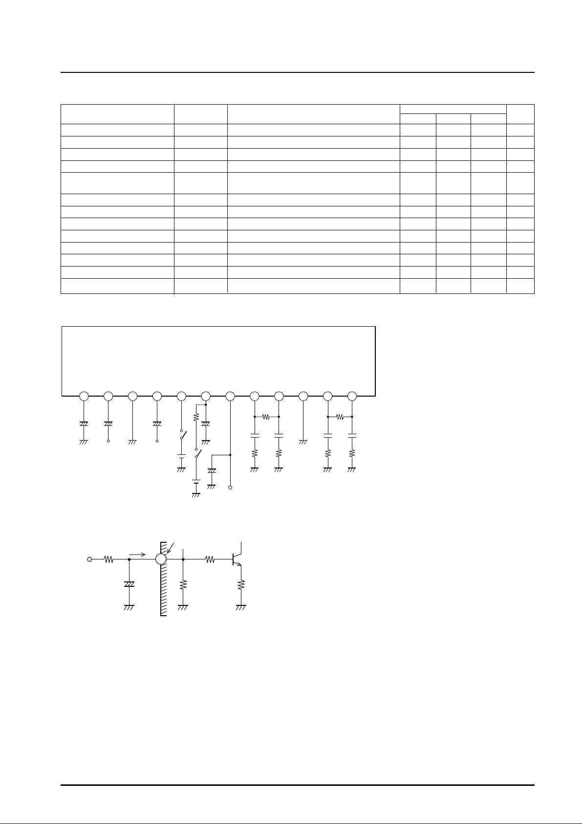
Measurement Circuit Diagram
LA4636
C9C80.1µF
PWR
GND+OUT2 --OUT2 --OUT1
0.1µF
Note: The LA4636 is basically
Top view
pin-compatible with the
LA4635, but there are
R
+OUT1
L
partial differences in
C7
C6
0.1µF
0.1µF
operation and usage,
PRE
IN2
25V
GND
+
4.7µF
16V
C1
4.7µF
C2
DC+IN1
1 2 3 4 5 6 7 10 11 12
+
47µF
C3
MUTE
STBY V
+
R1
22kΩ
16V
10µF
C4
10V
CC
8 9
R
L
including with regard to
R5
STBY
5V
Mute
R4
2.2Ω
+
C5
1000µF
5V
25V
V
CC
2.2Ω
R3
R2
2.2Ω
2.2Ω
externally connected
parts.
ILA00774
Pin 6 Equivalent Circuit Inside IC
Approximately 1.56V
6
20kΩ
2kΩ
5V
22kΩ
Imute
10µF
ILA00775
Signal Mute Function
• Connecting a CR of the recommended value (10 µF,
22 kΩ) to pin 6 of the IC and applying +5 V turns
signal mute on. This function mutes low-frequency
popping noises.
• The CR is for smoothing during attack and recovery.
2kΩ
The 10 µF capacitor also performs smoothing after the
starting time, so it is necessary even if the signal mute
function is not used.
If a 22 kΩ external resistor is used, the pin 6 inflow
current (Imute) will be approximately 160 µA when
+5 V is applied.
It is possible to change the external resistance value if
the voltage applied is changed or to match the capacity
of the microprocessor, but the popping noise level
could rise if the pin 6 inflow current increases too
much. It is therefore important to check the inflow
current whenever the resistance value is changed.
No. 6985-2/3
 Loading...