

SANYO LA4627 Datasheet
Ordering number : ENN6501
LA4627
Monolithic Linear IC
LA4627
Two-Channel Audio Frequency Power Amplifier
Overview
The LA4627 is a 2-channel power amplifier developed for use in radio/cassette player products.
The LA4627 reduces the number of required external components by 50% over earlier products
(BS/NF capacitors and oscillation prevention RC
components) and thus can contribute significantly
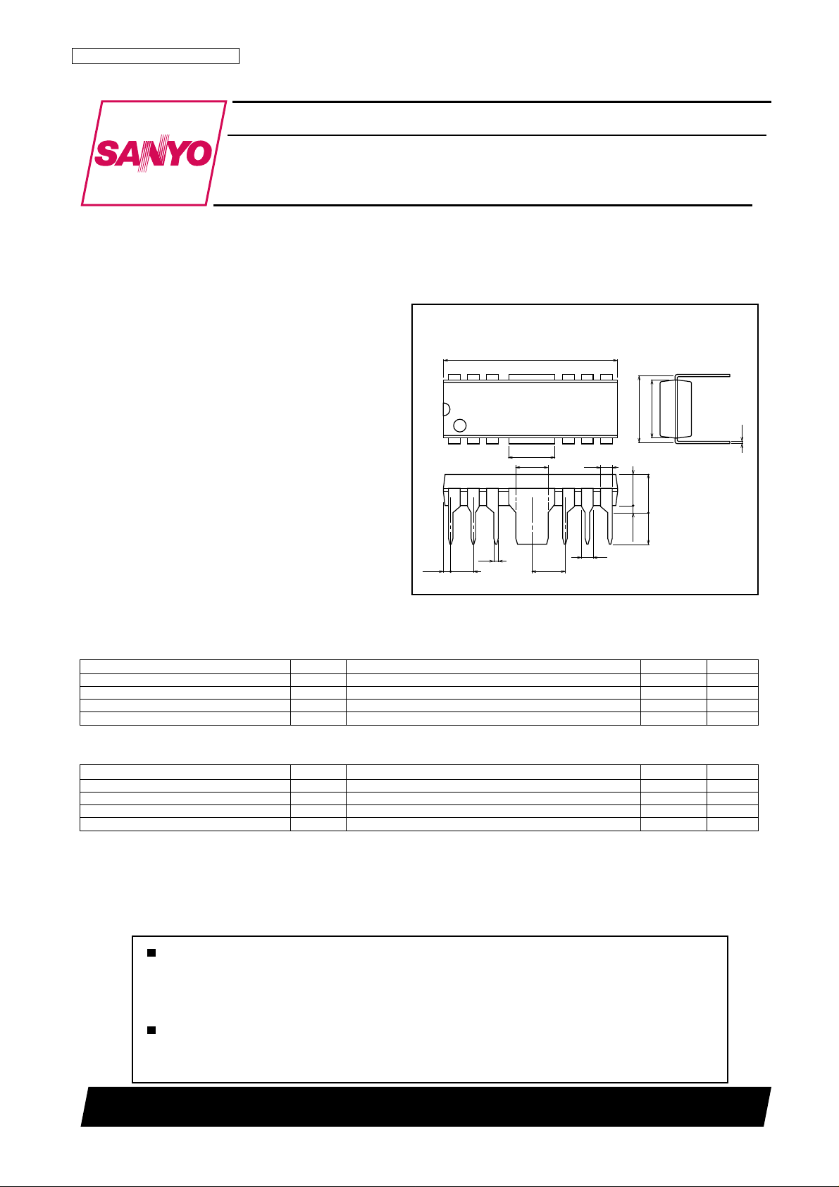
Package Dimensions
unit : mm
3022B-DIP12F
[LA4627]
19.0
12
7
to space saving in end products.
7.62
6.45
Features
•
Provided in the DIP12F.
•PO :2.0 W ✕ 2 (VCC = 9 V, RL = 4 Ω)
2.5 W ✕ 2 (VCC = 9 V, RL = 3 Ω)
• Standby function built in
(supports direct microcontroller control).
• Built-in thermal protection circuit.
(0.61)
1
0.5
2.54
5.12
3.6
3.81
6
1.25
(3.46)
4.26max
3.5
0.51min
1.3
SANYO : DIP12F(300mil)
Specifications
Maximum Ratings at Ta = 25°C
Maximum supply voltage V
Allowable power dissipation Pd max When mounted on the Sanyo-recommended PCB 4.0 W
Operating temperature Topr --25 to +75 °C
Storage temperature Tstg --55 to +150 °C
Parameter Symbol Conditions Ratings Unit
CC max
Rg = 0 22 V
0.4
Operating Conditions at Ta = 25°C
Recommended supply voltage V
Recommended load resistance R
Operating voltage range V
Recommended operating load resistance RL op 2.7 to 8.0 Ω
Parameter Symbol Conditions Ratings Unit
CC
L
op
CC
Any and all SANYO products described or contained herein do not have specifications that can handle
applications that require extremely high levels of reliability, such as life-support systems, aircraft's
control systems, or other applications whose failure can be reasonably expected to result in serious
physical and/or material damage. Consult with your SANYO representative nearest you before using
any SANYO products described or contained herein in such applications.
SANYO assumes no responsibility for equipment failures that result from using products at values that
exceed, even momentarily, rated values (such as maximum ratings, operating condition ranges, or other
parameters) listed in products specifications of any and all SANYO products described or contained
herein.
Under conditions such that the maximum ratings are not exceeded.
9V
3 Ω
5.0 to 20 V
SANYO Electric Co.,Ltd. Semiconductor Company
TOKYO OFFICE Tokyo Bldg., 1-10, 1 Chome, Ueno, Taito-ku, TOKYO, 110-8534 JAPAN
42000 RM (IM)
No.6501-1/6
LA4627
Operating Characteristics at Ta = 25°C, V
Parameter Symbol Conditions
Quiescent current I
Voltage gain V
Total harmonic distortion THD PO = 0.33 W(VO = 1.0 V) 0.1 0.8 %
Output power PO(1) THD = 10 % 2.0 2.5 W
Output noise voltage V
Ripple rejection ratio SVRR Rg = 0, fR = 100 Hz, Vr = 0 dBm, DIN AUDIO 45 52 dB
Channel separation CHsep Rg = 0, VO = 0 dBm, DIN AUDIO 50 60 dB
Standby current I
Input resistance Ri 20 30 40 kΩ
Standby pin voltage V
7
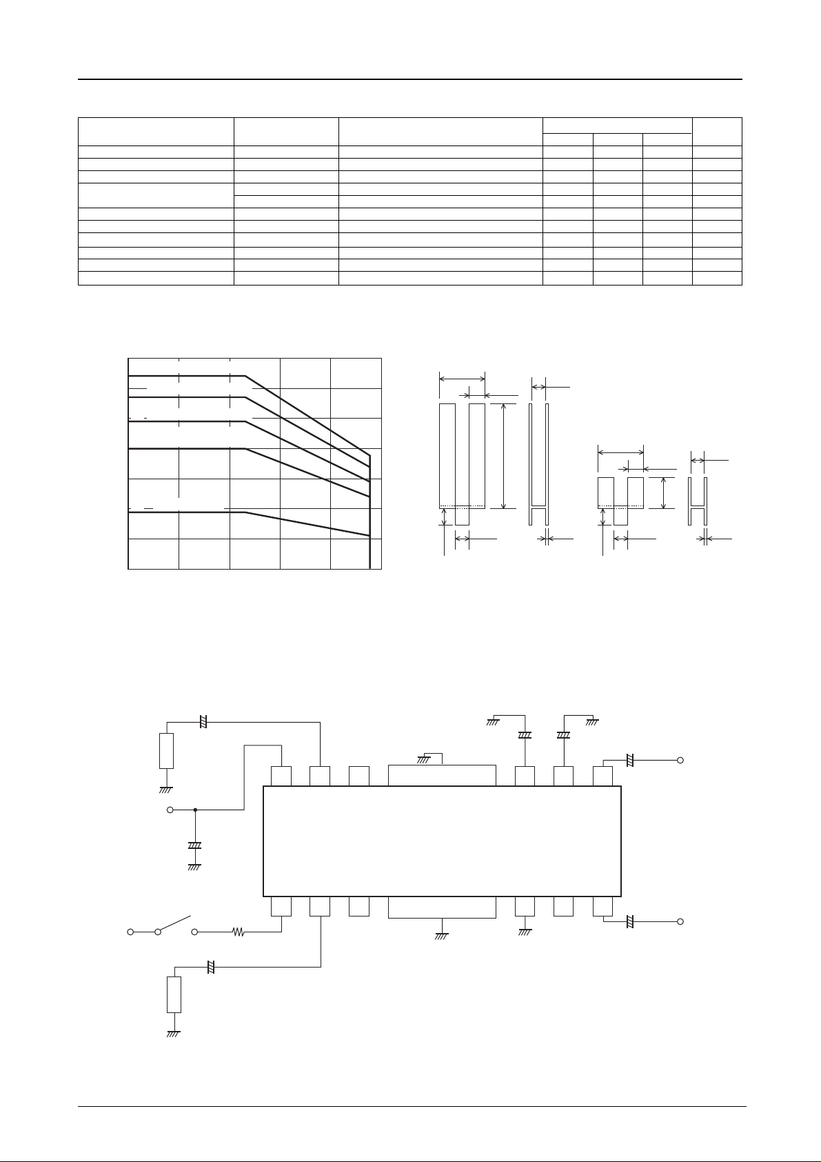
Copper heat sink (Fin 1)
6.4
6
Steel heat sink (Fin 1)
5.7
Steel heat sink (Fin 2)
4.9
5
Mounted on the recommended
printed circuit board.
4
4.0
3
Independent IC
1.9
2
Pd max -- Ta
CCO
G
PO(2) THD = 10 %, RL = 4 Ω 2.0 W
NO
ST
ST
= 9 V, RL = 3 Ω, f = 1 kHz, Rg = 600 Ω
CC
Ratings
Rg = 0 17 30 70 mA
VO = 0 dBm 43 45 47 dB
Rg = 0, DIN AUDIO 0.15 0.5 mVrms
Rg = 0 1.0 10 µA
The pin 1 voltage such that the amplifier is on 1.5 5.0 V
25.0
10.7
53.0
min typ max
8.7
25.0
10.7
12.0
Unit
8.7
1
Allowable power dissipation, Pd max -- W
0
--20 2006040 80
Ambient temperature, Ta -- °C
Application Circuit
STBY
+5 V
output 1
V
output 2
1000 µF
R
L
CC
R
L
+
+
1000 µF
+
1000 µF
*Rx
4.7 kΩ
3.6 0.5
ILA00055 ILA00056
12 11 10
OUT1V
CC
8.0
POWER
GND
Fin 1
+
4.7 µF
987Fin
P. P D C
100 µF
(R. F)
8.0
+
1 µF
+
IN1
LA4627
PRE
OUT2 IN2STBY
123 456
Fin
GND
+
1 µF
• Pins 3, 5, 10 must be left open.
*• Rx: If the STBY pin (pin 1) is used, observe the following:
Insert the resistor Rx in series to limit the inflowing current.
(The amplifier will be on when a voltage is applied to pin 1.)
3.6 0.5
Fin 2
input 1
input 2
Top view
ILA00057
No.6501-2/6
 Loading...