

Page 1
Ordering number : ENN2824A
D2599TH (OT)/12893TS/6089TA, TS No.2824-1/17
0.25
24
13
15.3
112
0.67
0.4
1.27
7.9
9.2
10.5
0.625
2.55max
2.250.1
SANYO: MFP24D
[LA4165M]
LA4165M
SANYO Electric Co.,Ltd. Semiconductor Company
TOKYO OFFICE Tokyo Bldg., 1-10, 1 Chome, Ueno, Taito-ku, TOKYO, 110-8534 JAPAN
Recording/Playback IC
for Micro-Cassette Tape Recorder
Monolithic Linear IC
Any and all SANYO products described or contained herein do not have specifications that can handle
applications that require extremely high levels of reliability, such as life-support systems, aircraft’s
control systems, or other applications whose failure can be reasonably expected to result in serious
physical and/or material damage. Consult with your SANYO representative nearest you before using
any SANYO products described or contained herein in such applications.
SANYO assumes no responsibility for equipment failures that result from using products at values that
exceed, even momentarily, rated values (such as maximum ratings, operating condition ranges, or other
parameters) listed in products specifications of any and all SANYO products described or contained
herein.
Overview
The LA4165M Recording-Playback IC combines the
functions required to design the recording and playback
systems and motor control circuits for micro- or
standard-cassette tape recorders into a single chip.
Functions provided include automatic audio input
sensing during recording with stepless setting of the onoff threshold using the playback volume control, and
LED indication that recording is in progress.
Recording and playback modes can be toggled using a
single control pin.
The LA4165M also has an on-chip preamp, power amp
and ALC circuits, and has been designed to operate with
a 3V power supply. The device is available in 24-pin
plastic MFPs.
Features
• Audio input sensor circuit
• LED driver circuit
• Motor control circuit
• ALC circuit
• Preamp and power amp circuits
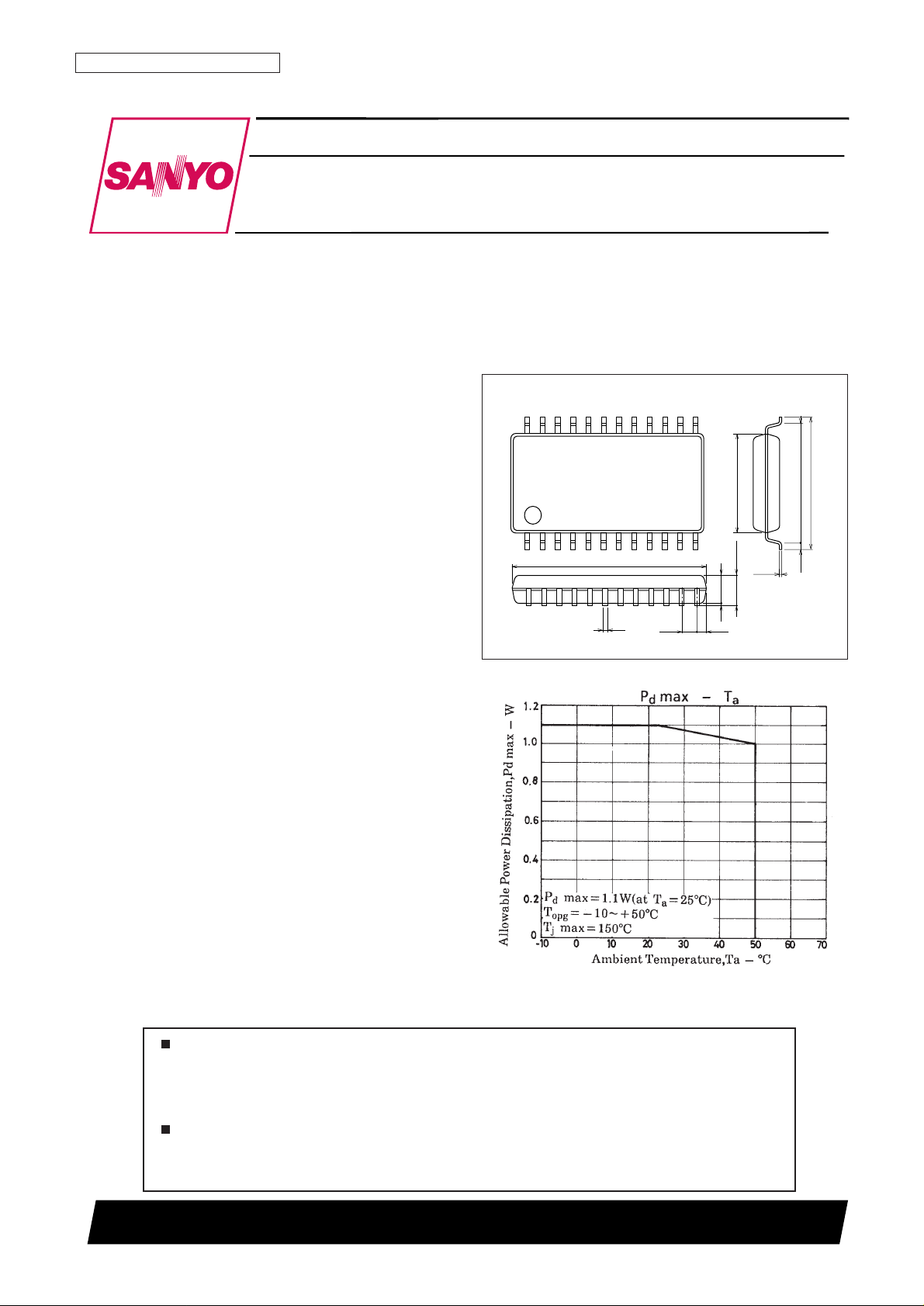
Package Dimensions
unit: mm
3108-MFP24D
Page 2

LA4165M
No. 2824-2/17
Parameter Symbol Conditions Ratings Unit
Maximum Supply Voltage V
CC
max 4.5 V
Allowable Power Dissipation Pd max G
VN
+ Power 1100 mW
Operating Temperature Topr –10 to +50 °C
Storage Temperature Tstg –55 to +150 °C
Specifications
Maximum Ratings at Ta = 25°C
Operating Conditions at Ta = 25°C
Parameter Symbol Conditions Ratings Unit
Recommended Supply Voltage V
CC
3.0 V
Operating Voltage Range V
CC
op 1.8 to 3.6 V
Power Amp Load Resistance R
L PWR
PLAY 4 Ω
REC 10 kΩ
Preamp Load Resistance R
L PRE
10 kΩ
Operating Characteristics at Ta = 25°C, VCC= 3.0 V, RL= 4 Ω (Play Power), RL= 10 kΩ (Rec Power),
RL= 10 kΩ (Pre), f = 1 kHz, 0 dBm = 0.775 V
Parameter Symbol Conditions
Ratings
Unit
min typ max
[Pre + Power]
Quiescent Current I
CC-R
REC mode, Vi = 0 V 12 25 38 mA
Quiescent Current I
CC-P
PLAY mode, Vi = 0 V 13 26 39 mA
Voltage Gain (Closed Loop) REC VG
TR
REC mode, VO = –5 dBm 62 64.5 67 dB
Voltage Gain (Closed Loop) PLAY VG
TP
PLAY mode, VO = –5 dBm 71 73.5 76 dB
[Pre Amp]
Voltage Gain (Closed Loop) REC VG1 R REC mode, V
O
= –10 dBm, RNF= 100 Ω 32.5 35 37.5 dB
Voltage Gain (Closed Loop) PLAY VG1 P PLAY mode, V
O
= –10 dBm, RNF= 100 Ω 42.5 45 47.5 dB
Maximum Output Voltage V
O
max THD=1%, PLAY mode 0.3 0.6 1.0 V
Equivalent Input Noise Voltage V
NI
PLAY mode, BPF = 20 Hz to 20 kHz 0.5 1.1 2.0 µV
Input Resistance RI 22.5 32.2 42 kΩ
Total Harmonic Distortion THD1 PLAY mode, V
O
= 0.4 V 0.01 0.11 1.0 %
[POWER AMP]
Voltage Gain VG2 V
O
= –5 dBm, RL= 4 Ω 26.0 28.5 31.0 dB
Output Power P
O
THD = 10 %, RL= 4 Ω 180 215 350 mW
Total Harmonic Distortion THD2 P
O
= 30 mW, RL= 4 Ω 0.05 0.5 1.5 %
Output Noise Voltage V
NO
RV = 0, RL = 4 Ω, BPF = 20 Hz to 20 kHz 5 25 100 µV
[ALC]
ALC Width ALC W
Input voltage above ALC cut-in
30 38 45 dB
voltage for ALC output to rise by 2.5 dB
ALC Distortion ALC THD Pre: Vi = –40 dBm 0.1 0.67 1.5 %
ALC Output ALC V
O
Pre: Vi = –40 dBm 0.35 0.46 0.55 V
ALC Start Input Level ALC V
IN
–66.5 –69 –71.5 dBm
[Voice Sensor]
Minimum Activation Input Voltage V
OP
min VR (10 kΩ) max –84.5 –81.5 –78.5 dBm
Maximum Activation Input Voltage V
OP
max VR (10 kΩ) max –62.5 –59.5 –56.5 dBm
Input Hysteresis V
O HL
369dB
[LED Drive]
LED Drive Current I
LED
Red LED 1.0 2.5 4.5 mA
Continued on next page.
Page 3
LA4165M
No. 2824-3/17
Continued from preceding page.
Parameter Symbol Conditions
Ratings
Unit
min typ max
[Moter Control]
Reference voltage V
refIm
= 100 mA 1.1 1.25 1.4 V
Quiescent Current I
d
Im= 100 mA 2.0 3.0 6.0 mA
Shunt Ratio K I
m
= 50–100 mA 45 50 55
Residual Voltage V
satIm
= 200 mA, V
ref
= V
cont
0.1 0.3 0.5 V
Voltage Characteristic of Reference Voltage
∆Vref
/∆VCCVCC= 1.8 to 4.5 V, Im= 100 mA 0 0.1 0.5 %/V
Vref
Voltage Characteristic of Shunt Ratio
∆K
/∆VCCVCC=2.0 to 4.5 V, Im= 50–100 mA
0 0.1 0.5 %/V
K
Current Characteristic of Reference Voltage
∆Vref
/∆ImIm= 50 to 200 mA 0 0.007 0.03 %/mA
Vref
Current Characteristic of Shunt Ratio
∆K
/∆ImIm= 50–100 mA to 150–200 mA –0.05 +0.005 +0.05 %/mA
K
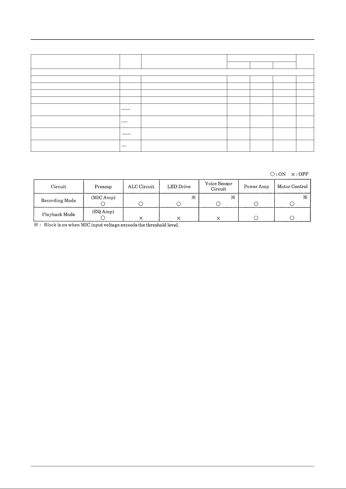
Recording/Playback Mode Functions
Page 4
LA4165M
No. 2824-4/17
Test Circuit
Page 5
LA4165M
No. 2824-5/17
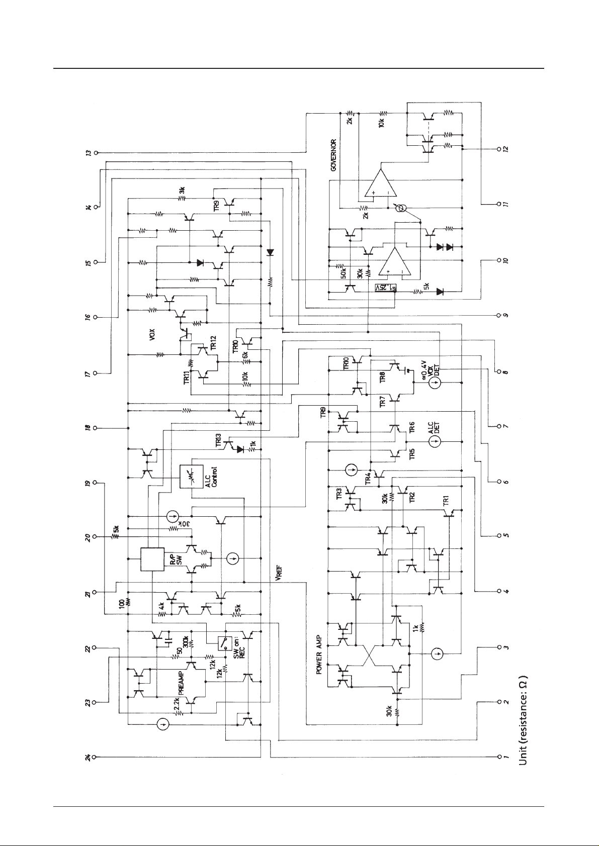
Equivalent Circuit
Page 6
LA4165M
No. 2824-6/17
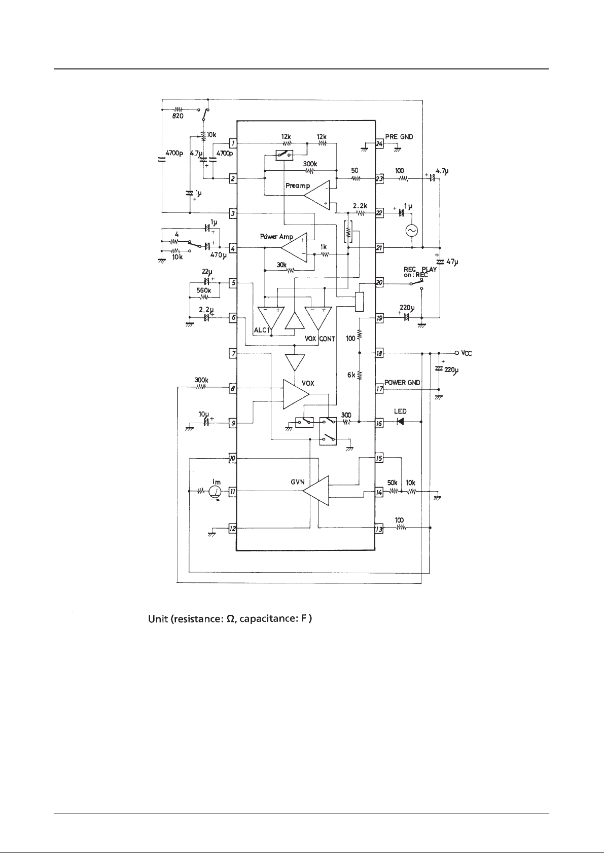
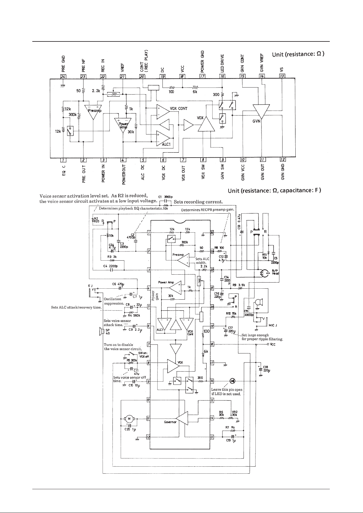
Block Diagram
Sample Application Circuit
Page 7

LA4165M
No. 2824-7/17
Functional Description
[Preamp]
• The frequency response characteristic of the low noise preamplifier is selected by the record/playback select pin
CONT (pin 20). If CONT is taken to ground to select record mode, the frequency response is flat. If CONT is left
open, playback mode is selected and the preamp has the NAM response curve.
[Power Amp]
• The power amplifier is suited to driving 4 Ω speakers and earphones.
[ALC]
• The ALC (Automatic Level Control) circuit is active in recording mode. It detects the power amp output level, and
controls the preamplifier input gain so that the power amp output level is constant.
[VOX CONT VOX]
• This circuit monitors the power amp output level, and turns the motor drive on or off. When the VOX CONT
circuit is operating, the LED drive output on pin 16 is active. The LED is extinguished if the supply voltage drops
to 1.8V.
[GVN]
• Motor control circuit. The external constants are determined according to the motor characteristics to keep the
motor speed constant.
Circuit Components
The function of each component, together with recommended values in parentheses, are listed below.
• C1: (2200 to 4700 pF)
Determines the frequency response of the signal voltage to the record/replay head during recording. Its value
should be selected according to the characteristics of the head.
• C2 : (4700 pF)
Determines the playback equalization frequency response.
• C3 : (2200 pF)
Suppresses high-frequency oscillation.
• C4 : (2200 to 4700 pF)
Controls high-frequency characteristics. C4 will interact with R3 to reduce the power amp input level if it is
too large.
• C5 : (2200 to 4700 pF)
Microphone input high-frequency filter. This should be selected according to the high-frequency cut-off and
the value of C21.
• C6 : (470 µF)
Couples the power amp output to the speaker or headphones. A value of 220 µF is adequate when using an 8 Ω
speaker or headphones.
• C7 : (1 µF)
Suppresses oscillation. For low-temperature operation (down to -10°C), a 0.47 µF tantalum electrolytic
capacitor should be used.
• C8 : (22 µF)
ALC control smoothing filter. C8 should not be too large, since this will also increase attack time.
• C9 : (0.1 to 2.2 µF)
Voice sensor (VOX) control smoothing filter. C8 should not be too large, since this will also increase turn-on
delay (the time for the motor drive circuit to turn on after the microphone input voltage reaches the set level).
Continued on next page.
Page 8

LA4165M
No. 2824-8/17
Continued from preceding page.
• C10 : (10 µF)
Voice sensor transient suppression. This prevents the motor drive from being turned on by large transient
pulses.
• C11 : (47 µF)
Determines the time constant for motor drive hold after the voice sensor circuit turns off. The motor drive
remains on for approximately 4 to 5 seconds if the resistor in parallel with R5 is 300 kΩ.
• C12 : (4.7 µF)
Together with series resistor R8, determines the preamp low-frequency cut-off. For C12 =4.7 µF and R8=100
Ω, the cut-off is approximately 200 Hz. The cut-off can be set to approximately 100 or 300 Hz by giving C12
a value of 10 µF or 2.2 µF, respectively.
• C13 : (0.47 µF)
Preamp input coupling capacitor.
• C14 : (2200 µpF)
EMI suppression capacitor. Select this according to the characteristics of the record/play head.
• C15 : (3300 pF)
Microphone input high-frequency filter.
• C16 : (220 µF)
Reference voltage decoupling capacitor.
• C17 : (220 µF)
Head DC supply ripple filter.
• C18 : (220 µF)
Supply decoupling capacitor.
• C19 : (1 to 10 µF)
Reference resistor (R7) bypass capacitor. Setting should be performed according to motor characteristics.
• C20 : (1 µF)
Load (motor) bypass capacitor. Setting should be performed according to motor characteristics.
• R1 : (5 to 15 kΩ)
Determines the flow of AC current through the head. Select this according to the head characteristics and ALC
level.
• R2 : (820 Ω)
Determines the microphone input level at which the voice sensor starts operating when VR1 is at minimum.
Larger values for R2 give voice sensor operation at lower microphone input signal levels.
• R3 : (3 kΩ)
Improves high-frequency response and reduces high-frequency distortion. Distortion above 5 kHz increases as
R3 decreases.
• R4 : (100 kΩ to 3 MΩ)
Determines ALC recovery time.
• R5 : (300 kΩ)
Voice sensor circuit control current resistor. R5 and C11 form the motor drive hold-time constant.
• R6 : (20 to 70 kΩ)
Determines motor speed. Select this according to the motor characteristics and the value of variable resistor
VR2.
Continued on next page.
Page 9

LA4165M
No. 2824-9/17
Continued from the preceding page.
• R7 : (100 to 300 Ω)
Select this according to the motor characteristics.
• R8 : (0 to 200 Ω)
Preamp negative feedback resistor.
• R9 : (3.9 kΩ)
Bias set resistor for electrostatic microphones.
The current into or out of the reference voltage pin (pin 21) should not be greater than ±1mA, or the biase of
other circuits will be affected. In particular, the power amplifier output power will be reduced.
• R10 : (15 kΩ)
Recording head bias set resistor. Since the bias reference voltage is the filtered DC voltage on pin 19,
excessive current should not be drawn by R10, or the reference voltage on pin 21 will be affected.
The following diagram shows the internal circuit of the reference voltage generator.
• R11 : (5 to 20 kΩ)
Select this to match the electrostatic microphone output characteristics.
• VR1 : (10 to 30 kΩ)
Adjusts the output level in playback mode, and the voice sensor sensitivity in record mode.
• VR2 : (5 to 30 kΩ)
Motor speed fine adjustment.
• LED : (Red LED)
Illuminated while recording. The LED starts to go out when VCCdrops to 2.2 V, and is completely
extinguished when VCCdrops to 1.8 V.
Page 10

LA4165M
No. 2824-10/17
Design Notes
1. Locate the LC4165M as close as possible to the power source, to prevent voltage and power loss due to supply line
resistance.
Change "Inner R1" to "Wiring resistance R1"
Change "Inner R2" to "Wiring resistance R2"
The total wiring resistance RT= R1+ R2causes the voltage VCat the IC supply pins to drop from the source voltage
VCCto
VC= VCC– ICC(R1+ R2)
The power output from the amplifier is equal to
P0 ∞ (VC)
2
Page 11

LA4165M
No. 2824-11/17
2. Keep the supply lines for the amplifier circuits separate from those for the motor drive circuit. This will reduce the
effect of motor noise on the amplifiers and help prevent voltage drop due to motor load from affecting the amplifier
supply voltage.
The recommended supply layout for the LA4165M power supply lines is shown below.
3. Do not connect a resistor to pin 6. The capacitor on this pin is being charged by a small current to determine the voice
sensor attack time. Bypassing this capacitor with a resistor will increase attack time, and possibly prevent the voice
sensor circuit from turning on.
4. The voice sensor circuit has approximately 6 dB hysteresis. It turns on at a voltage on pin 6 of approximately 1.1 V
and turns off at approximately 0.65 V. Biasing pin 6 higher than 0.65 V will cause it to remain on. The voice sensor
equivalent circuit is shown below.
Page 12

LA4165M
No. 2824-12/17
5. In record mode, grounding pin 8 will turn off the voice sensor circuit and keep the motor drive circuit operating
continuously.
6. Pin 7 is close to 0 V when the governor circuit is on, and close to VCCwhen it is off. The voice sensor output stage
equivalent circuit is shown below.
7. Pin 16 is used solely for driving an external LED, and should be left open when an LED is not used. It is active only
during record mode while the motor drive is on. The LED drive circuit is shown below.
Page 13

LA4165M
No. 2824-13/17
Page 14

LA4165M
No. 2824-14/17
Page 15

LA4165M
No. 2824-15/17
Page 16

LA4165M
No. 2824-16/17
Page 17

LA4165M
PS No. 2824-17/17
This catalog provides information as of December, 1999. Specifications and information herein are
subject to change without notice.
Specifications of any and all SANYO products described or contained herein stipulate the performance,
characteristics, and functions of the described products in the independent state, and are not guarantees
of the performance, characteristics, and functions of the described products as mounted in the customer’s
products or equipment. To verify symptoms and states that cannot be evaluated in an independent device,
the customer should always evaluate and test devices mounted in the customer’s products or equipment.
SANYO Electric Co., Ltd. strives to supply high-quality high-reliability products. However, any and all
semiconductor products fail with some probability. It is possible that these probabilistic failures could
give rise to accidents or events that could endanger human lives, that could give rise to smoke or fire,
or that could cause damage to other property. When designing equipment, adopt safety measures so
that these kinds of accidents or events cannot occur. Such measures include but are not limited to protective
circuits and error prevention circuits for safe design, redundant design, and structural design.
In the event that any or all SANYO products (including technical data, services) described or contained
herein are controlled under any of applicable local export control laws and regulations, such products must
not be exported without obtaining the export license from the authorities concerned in accordance with the
above law.
No part of this publication may be reproduced or transmitted in any form or by any means, electronic or
mechanical, including photocopying and recording, or any information storage or retrieval system,
or otherwise, without the prior written permission of SANYO Electric Co., Ltd.
Any and all information described or contained herein are subject to change without notice due to
product/technology improvement, etc. When designing equipment, refer to the “Delivery Specification”
for the SANYO product that you intend to use.
Information (including circuit diagrams and circuit parameters) herein is for example only; it is not
guaranteed for volume production. SANYO believes information herein is accurate and reliable, but
no guarantees are made or implied regarding its use or any infringements of intellectual property rights
or other rights of third parties.
 Loading...