

SANYO LA3375 Datasheet

Any and all SANYO products described or contained herein do not have specifications that can handle
applications that require extremely high levels of reliability, such as life-support systems, aircraft’s
control systems, or other applications whose failure can be reasonably expected to result in serious
physical and/or material damage. Consult with your SANYO representative nearest you before using
any SANYO products described or contained herein in such applications.
SANYO assumes no responsibility for equipment failures that result from using products at values that
exceed, even momentarily, rated values (such as maximum ratings, operating condition ranges,or other
parameters) listed in products specifications of any and all SANYO products described or contained
herein.
Monolithic Digital IC
Pilot Cancel-Provided PLL
FM MPX Demodulator for Car Stereos
Ordering number:ENN901E
LA3375
SANYO Electric Co.,Ltd. Semiconductor Company
TOKYO OFFICE Tokyo Bldg., 1-10, 1 Chome, Ueno, Taito-ku, TOKYO, 110-8534 JAPAN
Overview
The LA3375 integrates two functions : skip-noise prevention and pilot cancelling. It is a multiplex, 16-pin IC for
FM car stereos.
Functions
• Pilot-cancelling (level-following).
• Stereo noise controlling (SNC).
• High-cut control (HCC).
• Stereo-monaural automated selection (with priorities for
pilot inputs).
• VCO oscillation damping.
Features
• Low distortion (0.05% typ., 300-mV input, mono.).
• Power supply ripple rejection (35 dB typ.).
• Wide operating voltage range (VCC=6.5 to 14V).
• Small due to single-ended package.
• 3 mm pitch-pin spacing makes it easy to use in printed
circuit boards.
Specifications
Absolute Maximum Ratings at Ta = 25˚C
retemaraPlobmySsnoitidnoCsgnitaRtinU
egatlovylppusmumixaMV
tnerrucgnivirdpmaLI
noitapissidrewopelbawollAP
erutarepmetgnitarepOT
erutarepmetegarotST
Recommended Operating Conditions at Ta = 25˚C
retemaraPlobmySsnoitidnoCsgnitaRtinU
egatlovylppusrewopdednemmoceRV
egatlovlangistupmIv
xam 61V
CC
xam 04Am
L
xam 025Wm
d
Ta≤45˚C
rpo
gts
CC
i
Package Dimensions
unit:mm
3193-SIP16Z
[LA3375]
24.2
116
0.85
3.0
1.5
0.5
3.0
3.25
6.5
2.2min
0.25
1.5
SANYO : SIP16Z
8.8max
3.6
07+ot02–
˚C
521+ot04–
˚C
41ot5.6V
003ot002Vm
10700TH (KT)/90196RM/D177KI/8044KI/5205KI/ No.901–1/11
LA3375
Operating Characteristics at Ta = 25˚C, VCC=10V, vi=300mV, f=1kHz, L+R=90%, pilot=10%, Rg=20kΩ,
See specified Test Circuit.
retemaraPlobmySsnoitidnoC
tnerructnecseiuQI
noitarapeslennahCpeSB:1WS0405Bd
rotcafnoitrotsidlaruanoMDHTonomVm003=onom50.02.0%
rotcafnoitrotsidoeretSDHTTSniam50.02.0%
levelgnithgilpmaLV
siseretsyHh
egnarerutpaCRCVm03=tolip3±%
levellangistuptuOv
oitarN/SN/S
)3nip(ecnatsisertupnIr
oitarnoitcejerACSACS
egatlovtupnielbawollAv
noitaunettatuptuoCNSA
egatlovtuptuoCNSv
noitaunettatuptuoCCH
noitcejerelppirylppusrewoPR
egatlovgnippotsOCVpotsOCV 3.7V
ecnalablennahCaBHC 5.05.1Bd
rotcafnoitallecnactoliPLC
A
tt
A
tt
occ
L
y
o
i
jer
i
CNSV
tt
busV
o
r
p
)1(CCHV
)2(CCHV
Note : SW1 : A, SW2 : C unless otherwise specified.
nimpytxam
%01=tolip,%09=R+L0658021Vm
bus051512003Vm
k02=gR Ω 8647Bd
k01=gR Ω 0787Bd
k02=gR,%1=DHT Ω 007009Vm
k01=gR,%1=DHT Ω 054Vm
8
8
7
7
%01=tolip,%09=R–L,V6.0=5.8–0.3–3.0–Bd
%01=tolip,%09=R–L,V1.0= 5Vm
%01=tolip,%09=R+L,V6.0=0.51–0.9–5.0–Bd
%01=tolip,%09=R+L,V1=0.2–0Bd
sgnitaR
2282Am
36Bd
02kΩ
08Bd
53Bd
0252Bd
tinU
Specified test circuit
No.901–2/11
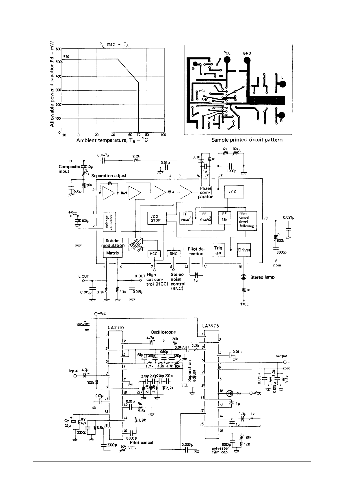
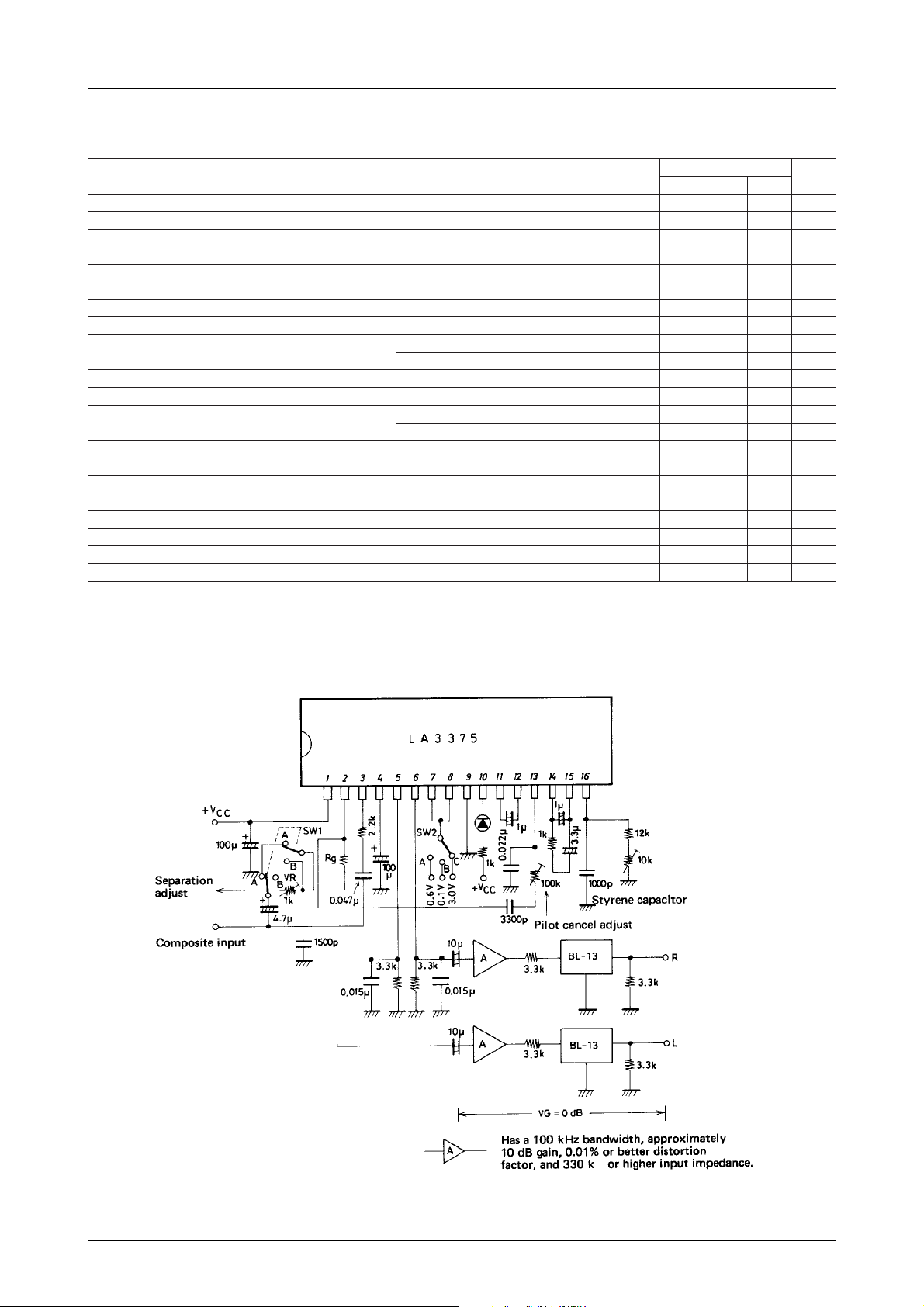
Sample application circuit 1
LA3375
Sample application circuit 2 : sample circuit for LA2110 and LA3375
No.901–3/11
LA3375
Cautions when employing sample application circuits
1) Adjust separation by 10kΩ potentiometer in low pass filter.
2) Adjust RS for noise detection sensitivity under strong to medium radio fields. Set at appropriate value.
3) Adjust noise AGC by CY and RY to enhance noise suppression in medium to weak radio fields.
4) Adjust pilot cancellation by 50kΩ potentiometer connected to pin 15 of LA2110.
5) Reponse speeds of pilot cancellation to follow levels can be varied by adjusting capacitance value of 1µF capacitor
connected across pins 11 and 12 of LA3375. Distortion factors deteriorate with reduction in value.
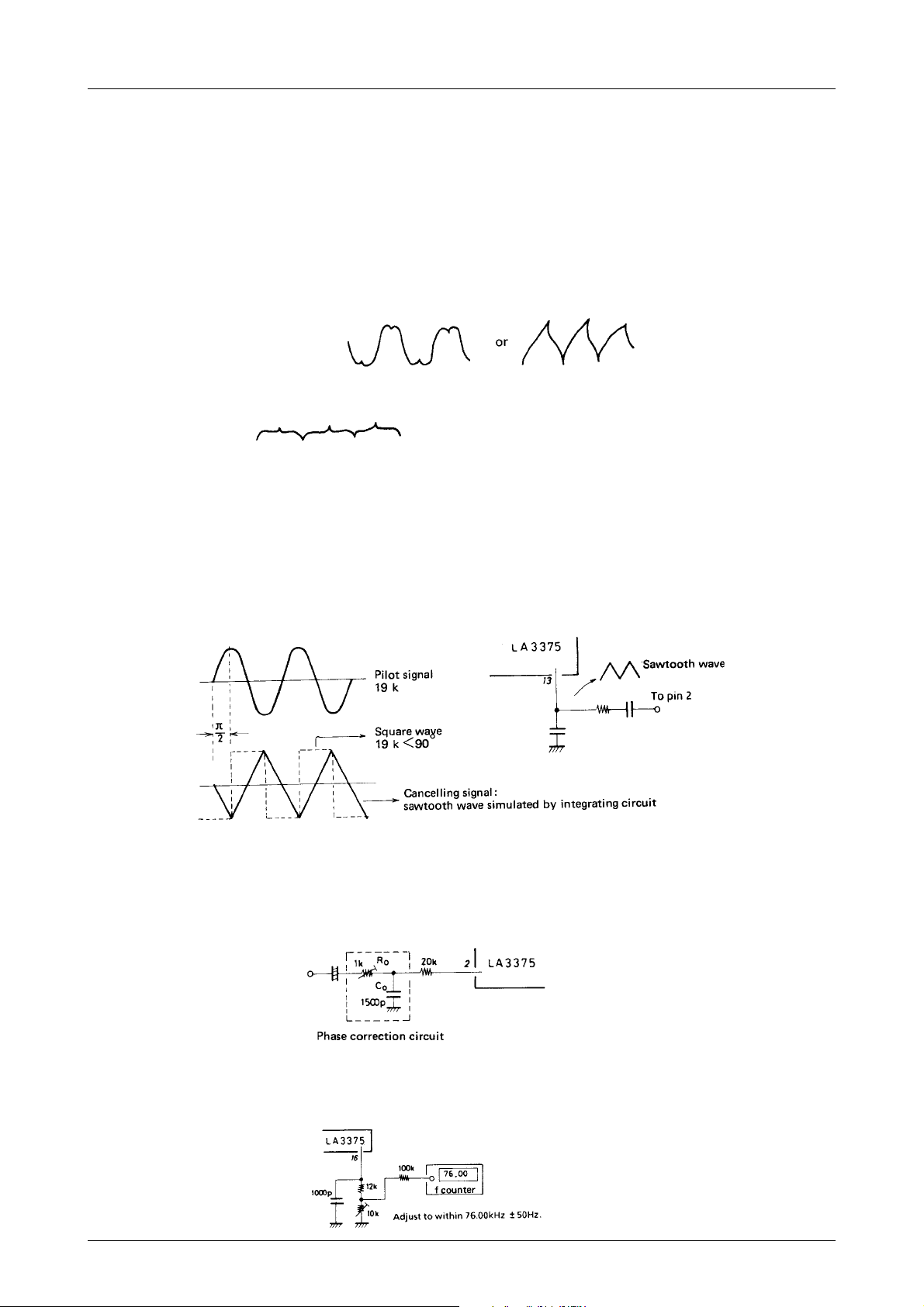
6) Adjusting pilot cancellation.
For example consider the sample application circuit 2. Assume the input signal consists only of pilot signals. First
connect an oscilloscope and a valve voltmeter to pin 2 of the LA2110. Set their ranges for V : 200mV/div. AC, H :
20µs/div.
When oscilloscope waveform is
turn pilot cancel control to change it to the following :
Then, adjust pilot cancel control to minimize indications of valve voltmeter.
When the LA3375 alone is used (sample application circuit 1), adjust cancel control through a 19kHz BPF to
minimize carrier leakage level at output pins (pins 5 and 6).
*Refer to the LA2110 catalog for LA3375/LA2110 applications and characteristics.
1. Pilot cancelling circuit
A level-following type has been used. Once set, it can easily accommodate varying pilot modulation depths among
stations. Cancelling signal is a sawtooth wave obtained by integrating a square wave that is proportionate in amplitude to pilot level with C and R.
2. Separation adjustments
The LA3375 has separation parameters that have been set to provide maximum separation when used in conjunction
with the LA2210, a noise-canceler IC, or the equivalent. The LA3375 by itself exhibits separation only in a 25 to 30
dB range. If a phase correction circuit is provided in the LA3375 input circuit, it can exhibit intrinsic separation
charactersitics, typically 50 dB.
3. Adjusting the free running frequency
Use a timing set resistor and a semi-set resistor, when connecting a frequency counter. Connect the counter with a
high impedance input to the connection between these resistors with a 100-kΩ resistor, as shown below.
No.901–4/11
 Loading...