

Page 1
NOTE: Locate serial number (shown on rear panel of unit) and record it here ➡
Please read this manual carefully before connecting your VCR and operating it for the first time.
Keep the manual in a safe place for future reference.
Only cassettes marked can be used with this video cassette recorder.
As an E
NERGY STAR
®
Partner,
FISHER has determined that this
product or product model meets
the E
NERGY STAR
®
guidelines for
energy efficiency.
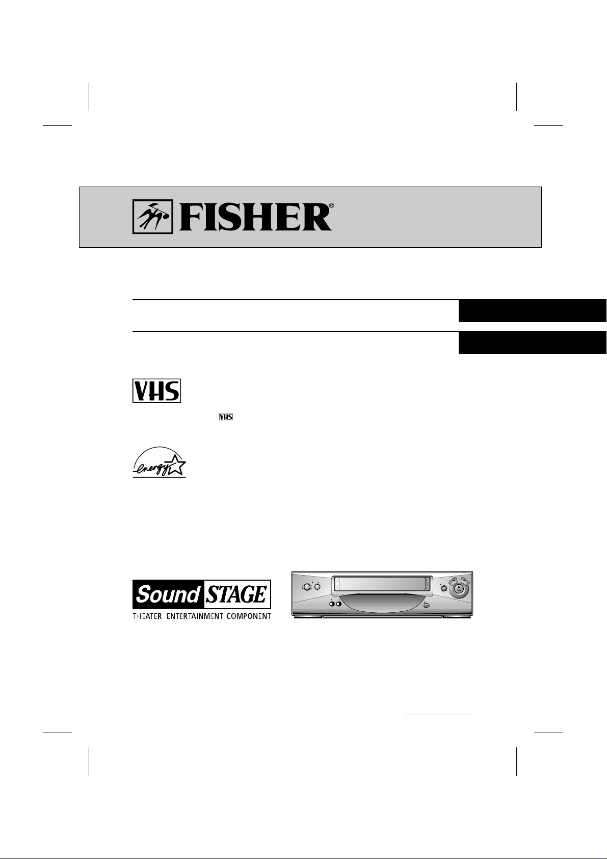
OPERATING INSTRUCTIONS
FVH-T621
Hi-Fi
Video Cassette Recorder
English
Español
Videograbador
I
index
STOP/ EJECTPOWER
CHANNEL
PAUSE
REC
REW FF
Page 2
2
WARNING :TO REDUCE THE RISK OF FIRE OR ELECTRIC SHOCK,
DO NOT EXPOSE THIS PRODUCT TO RAIN OR MOISTURE.
If you pour a cold liquid into a glass, water vapor in
the air will condense on the surface of the glass.
This is moisture condensation. Moisture condensation on the head drum, one of the most crucial
parts of the unit, will cause damage to the tape.
When the VCR is exposed to a rapid temperature
change from cold to warm, some condensation
will occur. Under this condition, connect the power
cord to the AC line, press POWERon and allow at
least two hours for the VCR to dry out.
MOISTURE CONDENSATION
RISK OF ELECTRIC SHOCK
DO NOT OPEN
CAUTION
CAUTION : TO REDUCE THE RISK
OF ELECTRIC SHOCK,
DO NOT REMOVE COVER (OR BACK);
NO USER-SERVICEABLE PARTS INSIDE
REFER SERVICING TO QUALIFIED SERVICE
PERSONNEL.
The serial number is found on the back of this
unit. This number is unique to this unit and not
available to others. You should record requested
information here and retain this guide as a permanent record of your purchase.
Model No. FVH-T621
Serial No.
CAUTION : TO PREVENT ELECTRIC SHOCK,
DO NOT USE THIS PLUG WITH AN EXTENSION CORD, RECEPTACLE OR OTHER OUTLET UNLESS THE PLUG CAN BE FULLY
INSERTED WITHOUT EXPOSING ANY PARTS
OF THE BLADES.
WARNING : Do not drop the tying band of the
power cord into the unit. Doing so might cause a
fire or an electrical shock. (See page 11.)
This lightning flash with arrowhead symbol within an equilateral triangle is intended to alert the user to the presence of
uninsulated dangerous voltage within the
product’s enclosure that may be of sufficient magnitude to constitute a risk of
electric shock to persons.
The exclamation point within an equilateral triangle is intended to alert the user to
the presence of important operating and
maintenance (servicing) instructions in the
literature accompanying the product.
IMPORTANT COPYRIGHT INFORMATION: Many
television programs and films are copyrighted. In
certain circumstances, copyright law may apply to
private in-home video taping of copyrighted materials.
FCC WARNING: This equipment may generate or
use radio frequency energy. Changes or modifications to this equipment may cause harmful interference unless the modifications are expressly
approved in the instruction manual. The user could
lose the authority to operate this equipment if an
unauthorized change or modification is made.
This device complies with Part 15 of the FCC Rules.
Operation is subject to the following two conditions:
(1) this device may not cause harmful interference,
and
(2) this device must accept any interference
received, including interference that may cause
undesired operation.
Page 3
3
CONTENTSFEATURES
INTRODUCTION
Features/Contents/Accessories . . . . . . . . . . . . . . . . . .3
Important Safety Instructions . . . . . . . . . . . . . . . . . .4-5
PREPARATION
Installation/VCR to TV Connection . . . . . . . . . . . . . . .6
Antenna to VCR Connections . . . . . . . . . . . . . . . . . . .7
Cable Antenna (CATV) Connections . . . . . . . . . . . . .8-9
VCR Output Channel Setting . . . . . . . . . . . . . . . . . . . .9
Control Names and Locations . . . . . . . . . . . . . . . .10-11
Remote Control . . . . . . . . . . . . . . . . . . . . . . . . . .12-13
Onscreen Display (OSD) . . . . . . . . . . . . . . . . . . . . . .14
Setting the Onscreen Display . . . . . . . . . . . . . . . . . .15
Setting the Setup Menu . . . . . . . . . . . . . . . . . . . . . . .16
Channel Selection . . . . . . . . . . . . . . . . . . . . . . . .17-18
Viewing TV Only . . . . . . . . . . . . . . . . . . . . . . . . . . . .18
Video Cassette Tapes . . . . . . . . . . . . . . . . . . . . . . . .19
Setting the Clock . . . . . . . . . . . . . . . . . . . . . . . . .20-21
PLAYBACK
Normal Playback . . . . . . . . . . . . . . . . . . . . . . . . . . . .22
Special Effects Playback . . . . . . . . . . . . . . . . . . .23-24
RECORDING
Normal Recording . . . . . . . . . . . . . . . . . . . . . . . . . . .25
Timer Recording . . . . . . . . . . . . . . . . . . . . . . . . . .26-28
Instant Timer Recording . . . . . . . . . . . . . . . . . . . . . .29
Dubbing and Editing . . . . . . . . . . . . . . . . . . . . . . . . .30
ADDITIONAL INFORMATION
VHS Hi-Fi Stereo System/MTS Broadcast . . . . . .31-32
Tape Counter Memory Feature . . . . . . . . . . . . . . . . .33
Editing a Recording . . . . . . . . . . . . . . . . . . . . . . . . . .34
Operating Hints . . . . . . . . . . . . . . . . . . . . . . . . . . . . .34
Video Head Cleaning . . . . . . . . . . . . . . . . . . . . . . . .34
Troubleshooting . . . . . . . . . . . . . . . . . . . . . . . . . . . .35
Specifications . . . . . . . . . . . . . . . . . . . . . . . . . . . . . .36
• Auto Clock set System
• Energy Save Function
• MTS Hi-Fi Stereo
• 1Year/8 Event Timer with
DAILY and WEEKLY Function
• Auto Power and Playback
Functions
• Instant Timer Recording
• Real-Time Tape Counter,
Tape Remaining Time
• Clean Still, Slow, Frame
Advance, Advertisement Jump
• Auto Tracking Function/Auto
Head Cleaner
• Onscreen Display of Function
• Trilingual Onscreen
Programming
(English/Spanish/French)
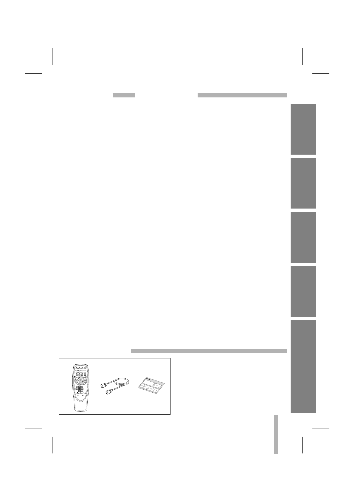
Check to make sure that all accessories listed
left have been included with your VCR.
•
Depending on your antenna system, you may
need a different type of Combiner (Mixer) and
Separator (Splitter). You can purchase them at
most electronics stores. For further details, ask
your nearest authorized service center.
ACCESSORIES
INTRODUCTION
PREPARATION PLAYBACK
RECORDING ADDITIONAL INFORMATION
Remote Control RF Coaxial Cable
POWER
123
TV/VCR
456
Ad JUMP
789
SLOW INPUT SP/SLP
0
EJECT
REC
PAUSE
REW FF
PLAY
STOP
ENTER
MENU
CLK/COUNT
CH
TRACK
CLEAR
VOL TV CH TV CH
VOL
TV POWER
TV INPUT
Quick Setup
Guide
Q
u
i
c
k
XXXXX
S
e
t
u
XXXXX
p
XXXXX
G
u
i
d
XXXXX
e
XXXXX
XXXXX
XXXXX
XXXXX
XXXXX
XXXXX
XXXXX
XXXXX
XXXXX
XXXXX
XXXXX
XXXXX
XXXXX
XXXXX
XXXXX
XXXXX
XXXXX
XXXXX
XXXXX
XXXXX
XXXXX
XXXXX
XXXXX
XXXXX
Page 4

4
INTRODUCTION
IMPORTANT SAFETY INSTRUCTIONS
1. Read Instructions
All the safety and operating instructions should
be read before the product is operated.
2. Follow Instructions
All operating and use instructions should be followed.
3. Retain Instructions
The safety and operating instructions should be
retained for future reference.
4. Heed Warnings
All warnings on the product and in the operating instructions should be adhered to.
5. Cleaning
Unplug this product from the wall outlet before
cleaning. Do not use liquid cleaners or aerosol
cleaners. Use a damp cloth for cleaning.
6. Water and Moisture
Do not use this product near water – for example, near a bath tub, wash bowl, kitchen sink,
or laundry tub, in a wet basement, or near a
swimming pool.
7. Accessories
Do not place this product on an unstable cart,
stand, tripod, bracket, or table. The product
may fall, causing serious injury to a child or
adult, and serious damage to the product. Use
only with a cart, stand, tripod, bracket, or table
recommended by the manufacturer, or sold
with the product. Any mounting of the product
should follow the manufacturer’s instructions,
and should use a mounting accessory recommended by the manufacturer.
8. Transporting Product
A product and cart combination should be
moved with care. Quick stops, excessive force,
and uneven surfaces may cause the product
and cart combination to overturn.
9. Attachments
Do not use attachments not recommended by
the product manufacturer as they may cause
hazards.
10. Ventilation
Slots and openings in the cabinet are provided
for ventilation and to ensure reliable operation
of the product and to protect it from overheating, and these openings must not be blocked or
covered. The openings should never be
blocked by placing the product on a bed, sofa,
rug, or other similar surface. This product
should not be placed in a built-in installation
such as a bookcase or rack unless proper ventilation is provided or the manufacturer’s
instructions have been adhered to.
11. Power Sources
This product should be operated only from the
type of power source indicated on the marking
label. If you are not sure of the type of power
supply to your home, consult your product dealer or local power company. For products
intended to operate from battery power, or
other sources, refer to the operating instructions.
12. Grounding or Polarization
This product is equipped with a polarized alternating-current line plug (a plug having one
blade wider than the other). This plug will fit
into the power outlet only one way. This is a
safety feature. If you are unable to insert the
plug fully into the outlet, try reversing the plug.
If the plug should still fail to fit, contact your
electrician to replace your obsolete outlet. Do
not defeat the safety purpose of the polarized
plug.
13. Power-Cord Protection
Power-supply cords should be routed so that
they are not likely to be walked on or pinched
by items placed upon or against them, paying
particular attention to cords at plugs, convenience receptacles, and the point where they
exit from the product.
PORTABLE CART WARNING
Important safeguards for you and your new product
Your product has been manufactured and tested with your safety in mind. However, improper use can
result in potential electrical shock or fire hazards. To avoid defeating the safeguards that have been built
into your new product, please read and observe the following safety points when installing and using your
new product, and save them for future reference.
Observing the simple precautions discussed in this section of the operating guide can help you get many
years of enjoyment and safe operation that are built into your new product.
Page 5
5
INTRODUCTION
IMPORTANT SAFETY INSTRUCTIONS (Cont’d)
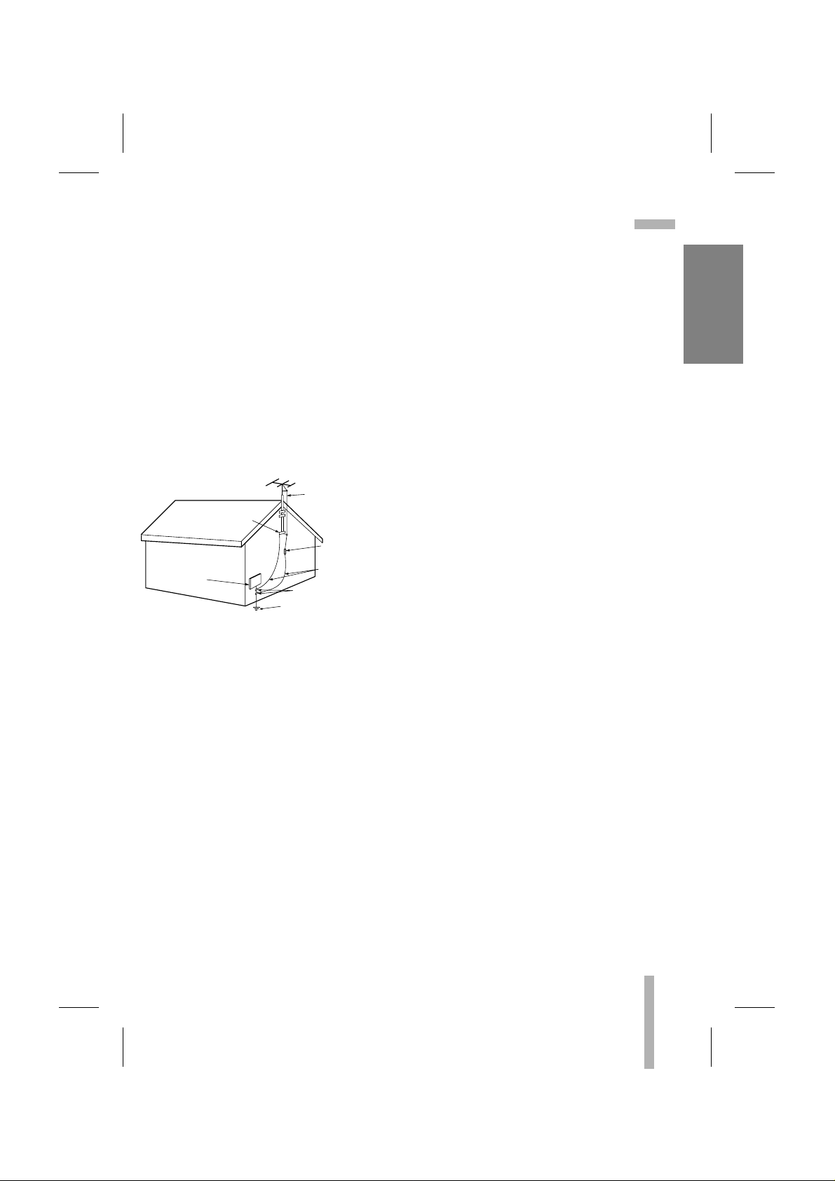
14. Outdoor Antenna Grounding
If an outside antenna or cable system is connected to the product, be sure the antenna or
cable system is grounded so as to provide
some protection against voltage surges and
built-up static charges. Article 810 of the
National Electrical Code (U.S.A), ANSI/NFPA
70 provides information with regard to proper
grounding of the mast and supporting structure, grounding of the lead-in wire to an antenna discharge unit, size of grounding conductors, location of antenna-discharge unit, connection to grounding electrodes, and requirements for the grounding electrode.
15. Lightning
For added protection for this product (receiver)
during a lightning storm, or when it is left unattended and unused for long periods of time,
unplug it from the wall outlet and disconnect
the antenna or cable system. This will prevent
damage to the product due to lightning and
power-line surges.
16. Power Lines
An outside antenna system should not be
located in the vicinity of overhead power lines
or other electric light or power circuits, or
where it can fall into such power lines or circuits. When installing an outside antenna system, extreme care should be taken to keep
from touching such power lines or circuits as
contact with them might be fatal.
17. Overloading
Do not overload wall outlets and extension
cords as this can result in a risk of fire or electric shock.
18. Object and Liquid Entry
Never push objects of any kind into this product through openings as they may touch dangerous voltage points or short-out parts that
could result in a fire or electric shock. Never
spill liquid of any kind on the product.
19. Servicing
Do not attempt to service this product yourself
as opening or removing covers may expose
you to dangerous voltage or other hazards.
Refer all servicing to qualified service personnel.
20. Damage Requiring Service
Unplug this product from the wall outlet and
refer servicing to qualified service personnel
under the following conditions:
a. If the power-supply cord or plug is damaged.
b.If liquid has been spilled, or objects have
fallen into the product.
c. If the product has been exposed to rain or
water.
d.If the product does not operate normally by
following the operating instructions. Adjust
only those controls that are covered by the
operating instructions as an improper adjustment of other controls may result in damage
and will often require extensive work by a
qualified technician to restore the product to
its normal operation.
e. If the product has been dropped or the cabi-
net has been damaged.
f. If the product exhibits a distinct change in
performance.
21. Replacement Parts
When replacement parts are required, be sure
the service technician has used replacement
parts specified by the manufacturer or have the
same characteristics as the original part.
Unauthorized substitutions may result in fire,
electric shock, or other hazards.
22. Safety Check
Upon completion of any service or repairs to
this product, ask the service technician to perform safety checks to determine that the product is in proper operating condition.
23. Heat
The product should be situated away from heat
sources such as radiators, heat registers,
stoves, or other products (including amplifiers)
that produce heat.
EXAMPLE OF GROUNDING ACCORDING TO
NATIONAL ELECTRICAL CODE INSTRUCTIONS
Antenna Lead in Wire
Ground
Clamp
Antenna Discharge Unit
(NEC Section 810-20)
Grounding Conductors
Electric Service
Equipment
NEC - NATIONAL ELECTRICAL CODE
(NEC Section 810-21)
Ground Clamps
Power Service Grounding
Electrode System
(NEC Art 250, Part H)
Page 6
6
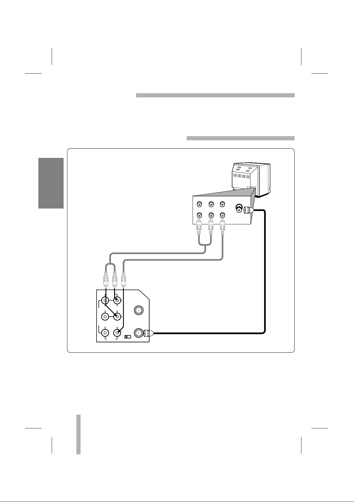
PREPARATION
INSTALLATION
Placing your VCR on the top of or under the TV receiver may result in interference appearing on
the TV screen when the VCR is on. If this occurs, move the VCR to a position alongside the TV
receiver.
VCR TO TV CONNECTION
AUDIO
LINE1(AUX1)
R
L
IN
IN
OUT
OUT
ANT.IN
VIDEO
CH.
34
VHF/UHF
/CATV
To VHF/UHF/CATV
VCR’s Back Panel
TV set
Cable/
Antenna
R-AUDIO-L
VIDEO
IN
OUTINOUT
From AUDIO/VIDEO OUT
To AUDIO/VIDEO IN
AUDIO/VIDEO Cable (Not supplied)
75 ohm Coaxial Cable (Supplied)
When using the RF coaxial cable (Supplied)
Connect the 75-ohm Coaxial Cable to VHF/UHF/CATV
on the VCR. Connect the other end to the 75-ohm
antenna input on back of the TV.
When using the Audio/Video cable (Not supplied)
If your TV has A/V input jacks, you may connect your VCR’s AUDIO/VIDEO jacks on back of
your TV.
Direct audio/video connections usually result in a better picture and sound quality for tape
playback. Please see your TV’s owner’s manual for details. Then set your TV to the VIDEO
mode using the TV/VIDEO button on your TV.
Page 7
7
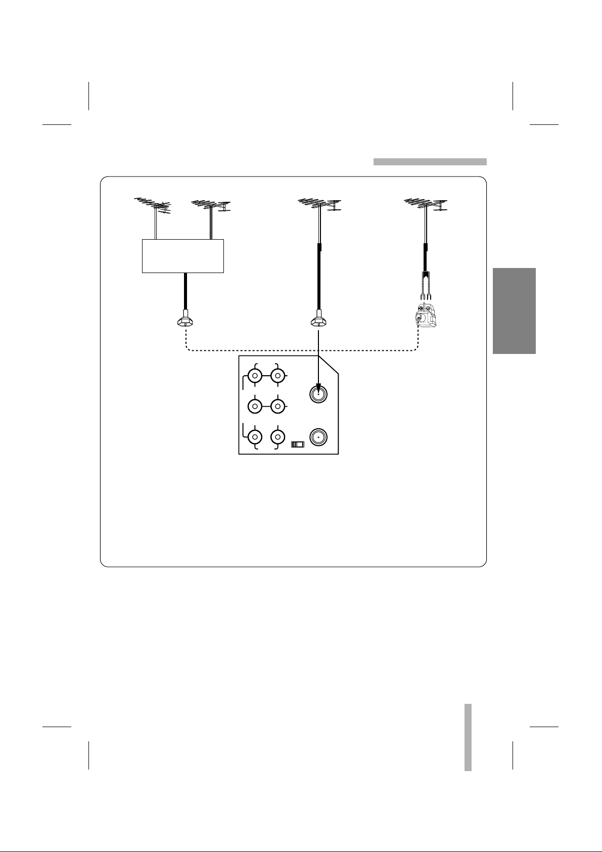
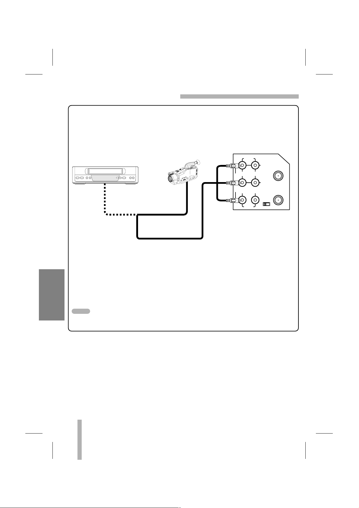
PREPARATION
ANTENNA TO VCR CONNECTIONS
AUDIO
LINE1(AUX1)
R
L
IN
IN
OUT
OUT
ANT.IN
VIDEO
CH.
34
VHF/UHF
/CATV
VCR’s Back Panel
VHF AntennaUHF Antenna
VHF/UHF mixer
(Not supplied)
300 ohm
Twin-Lead
Cable
75 ohm
Coaxial
Cable
75 ohm
Coaxial
Cable
300/75 ohm
Adaptor
(Not supplied)
VHF/UHF Antenna
VHF/UHF Antenna
300 ohm
twin lead
OR OR
1 Disconnect the antenna leads from the rear of the TV receiver.
2 Identify the type of cable from your antenna. If it is a round cable as illustrated, it is a
75 ohm coaxial antenna cable. This cable will connect directly to the connector marked
ANT.IN on your VCR.
If your antenna lead wire is a flat type antenna cable, connect it to a Antenna Adaptor
(300-ohm to 75-ohm) (not supplied) and slip the Adaptor onto the ANT.IN connector. The
Adaptor does not screw on to the VCR, it just slips over the connector.
Page 8
8
PREPARATION
CABLE ANTENNA(CATV) CONNECTIONS
AUDIO
LINE1(AUX1)
R
L
IN
IN
OUT
OUT
ANT.IN
VIDEO
CH.
34
VHF/UHF
/CATV
75 ohm
Cable
System
75 ohm
Cable
System
IN
OUT
CABLE CONVERTER
VCR’s Back Panel
75 ohm Coaxial Cable (Supplied)
TV set
Cable/
Antenna
OR
Without Cable Box
If your cable wire is connected to your TV without a converter or descrambler box, unscrew
the wire from your TV and attach it to the ANT.IN connector on the VCR. Use the supplied
round coaxial cable to connect between the VCR’s VHF/UHF/CATV connector and the 75
ohm antenna input connector on the TV. With this connection, you can receive all midband,
super band, and hyperband channels.
With Cable Box
If a converter is required in your cable system, follow the instruction below:
The cable hookup permits both TV and VCR operation.
To view or record CATV channel
1 Set the TV channel to the video output channel as located on the back of the VCR (CH3
or CH4).
2 Set the VCR channel selector to the output channel of the Cable Converter box by press-
ing the CH/TRACK (▲/▼) or number (0-9) of your VCR. (Example: CH3)
3 Select the channel to view at the Cable Converter Box.
• With this connection, you CANNOT record one program while viewing another.
• Channel memory programming is not needed when using the connection.
NOTES
Page 9
9
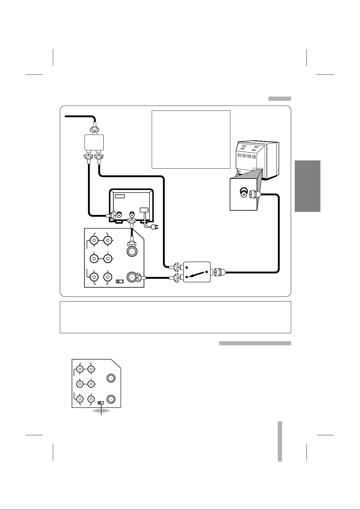
PREPARATION
CABLE ANTENNA(CATV) CONNECTIONS (Cont’d)
AUDIO
LINE1(AUX1)
R
L
IN
IN
OUT
OUT
ANT.IN
VIDEO
CH.
34
VHF/UHF
/CATV
2-way Splitter
(Not supplied)
A/B Switch
(Not supplied)
75 ohm Cable System
IN
OUT
CABLE CONVERTER
VCR’s Back Panel
75 ohm Coaxial
Cable (supplied)
TV set
Cable/
Antenna
This cable hookup allows you
either to view and record the
same channel (scrambled or
non-scrambled signal), or to
view one channel (non-scrambled signal) while recording
another channel (scrambled or
non-scrambled signal).
Note to CATV system installer (USA only): This reminder is provided to call the CATV
system installer’s attention to Section 820-40 of the NEC which provides guidelines for proper
grounding and, in particular, specifies that the cable ground shall be connected to the
grounding system of the building, as close to the point of cable entry as practical.
During playback of a video tape, and when press TV/VCR to set
the VCR mode, the VCR OUTPUT converter changes the video
and audio signals to the same type of signals that are used for
TV broadcasts. Set the VCR OUTPUT channel switch (marked
CH3, CH4 and located on the rear panel) to channel 3 or 4.
Select the channel that is not used for TV broadcasts in your
area.
This is your VCR OUTPUT channel. To play a tape, or to watch
TV using the VCR’s built-in tuner, always set your TV’s channel
selector to the same channel (3 or 4).
AUDIO
LINE1(AUX1)
R
L
IN
IN
OUT
OUT
ANT.IN
VIDEO
CH.
34
VHF/UHF
/CATV
VCR OUTPUT CHANNEL SWITCH
VCR OUTPUT CHANNEL SETTING
VCR’s BACK PANEL
Page 10
10
PREPARATION
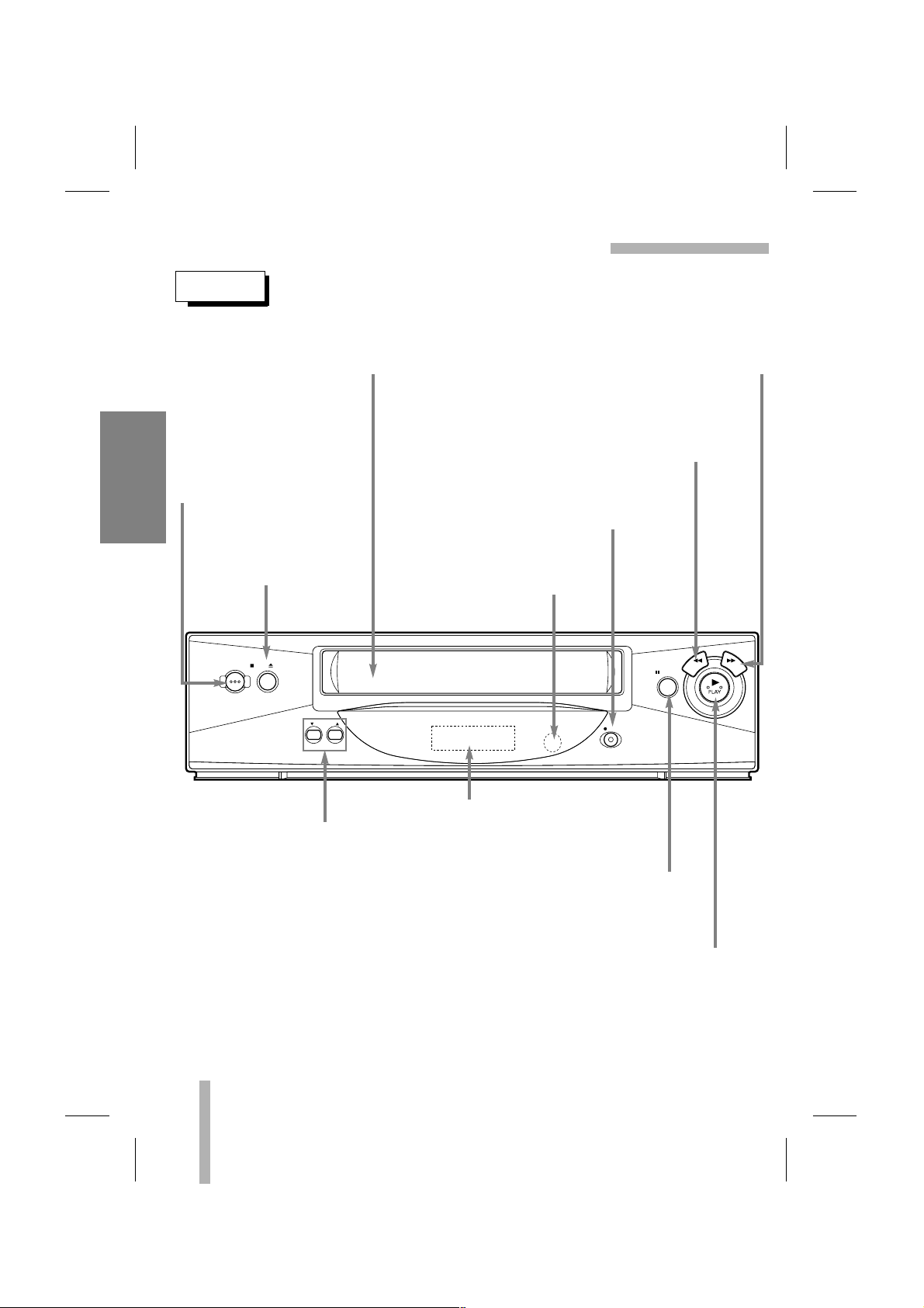
CONTROL NAMES AND LOCATIONS
FRONT
CASSETTE COMPARTMENT
Where the video cassette is inserted.
POWER ON/OFF
To turn the VCR on and off.
While plugged into an AC
outlet, the VCR consumes
3W of electrical power in
OFF condition.
STOP/EJECT
To stop the tape.
To eject the tape in the
VCR.
PLAY
To play back a recorded tape (page 22).
REW (Rewind)
To rewind the tape during the STOP mode or
for fast reverse picture search (page 23).
INFRARED REMOTE SENSOR
Receives the signal from the
infrared remote control.
CHANNEL (DD/EE)
To scan up or down through
memorized channels (page 17)
or to adjust manually the tape’s
picture onscreen (page 22).
VCR Function Indicator Panel
Details are on the next page.
REC (RECORD)
To record normally (page 25) or to activate
Instant Timer Recording (page 29).
PAUSE/STILL
To put playback on still (page 23) or to
pause recording (page 25).
FF (Fast Forward)
To advance the tape during the STOP mode or for
fast forward picture search (page 23).
STOP/ EJECTPOWER
CHANNEL
PAUSE
REC
REW FF
Page 11
11
PREPARATION
AUDIO
LINE1(AUX1)
R
L
IN
IN
OUT
OUT
ANT.IN
VIDEO
CH.
34
VHF/UHF
/CATV
CONTROL NAMES AND LOCATIONS (Cont’d)
REAR
INDICATOR PANEL
ANTENNA INPUT CONNECTOR
Connect the VHF/UHF/CATV antenna to this terminal.
AUDIO OUT (L/R) JACKS; Connect this terminal to the audio input terminal on an external unit (Audio System, TV/Monitor, Another VCR).
VIDEO OUT JACK; Connect this terminal to the video input terminal on an external unit
(TV/Monitor, Another VCR).
AUDIO IN (L/R) JACKS; Connect the audio output cable from an external unit (ex. Audio
system, TV/Monitor, DVD player, Another VCR) to this terminal.
VIDEO IN JACK; Connect the video output cable from an external unit (ex. Audio system,
TV/Monitor, DVD player, Another VCR) to this terminal.
When using this AUDIO/VIDEO IN jacks, select the input channel “LINE” at the VCR.
Press INPUT to select “LINE”.
POWER CORD
Connect only to an AC 120V, 60Hz outlet.
VCR OUTPUT CHANNEL SELECT SWITCH
Set this switch to channel 3 or 4.
VHF/UHF/CATV ANTENNAOUTPUT CONNECTOR
Connect this terminal to the VHF or UHF
antenna terminals on the back of a TV.
Cassette indicator
Lights while a cassette is
inserted, and flashes while
ejecting a cassette.
Record indicator
VCR indicator
Use TV/VCR on the remote control
to turn this indicator ON or OFF.
ON: for playback, VCR programming
or watching TV programs through the
VCR tuner
OFF: for watching TV programs
through TV tuner
REC
VCR
TIMER
AM
Clock/Tape operation indicator
HI — VCR is turned on.
BYE — VCR is turned off.
TIMER indicator
AM indicator
(PM is not displayed)
WARNING : Do not drop the tying
band of the power cord into the
unit. Doing so might cause a fire
or an electrical shock.
NOTE
Page 12

12
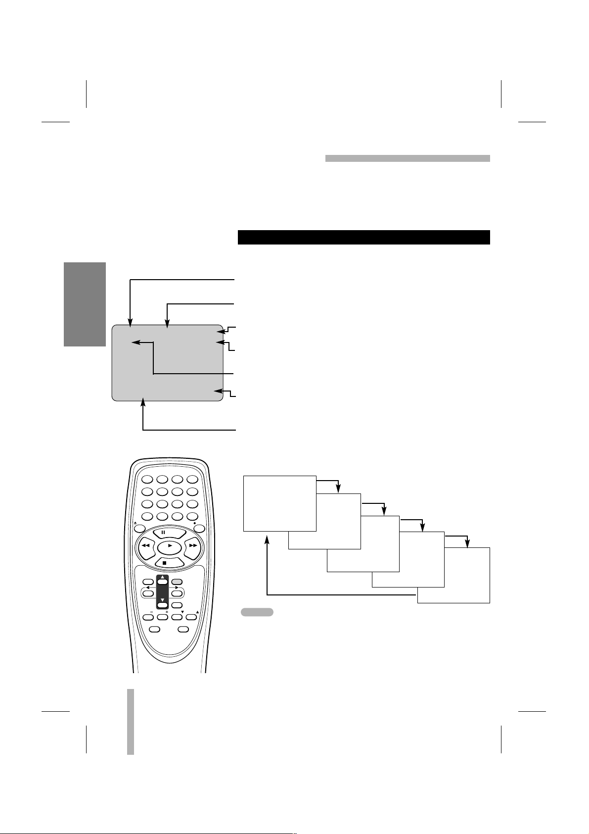
PREPARATION
REMOTE CONTROL
The remote control is used for most of the operations and features of the VCR. Before proceeding, put batteries in the remote and become familiar with the buttons. Use only type AA batteries. The maximum operating distance is about 25 feet.
The POWER, PLAY, PAUSE, FF, REW and REC buttons on the remote control unit perform the
same functions as the corresponding buttons on the VCR. The remaining buttons are on the
remote control unit only.
NUMBER buttons
Use these buttons, numbered 0-9, to select a channel.
TV/VCR
To view channels selected by the VCR tuner or by the
TV tuner (page 9, 25).
Ad JUMP
To fast forward picture search through 30 seconds of
recording (page 24).
SP/SLP
Use to select recording speed (page 25).
ENTER (CLK/COUNT)
Accesses the onscreen menu (page 15).
Displays functions on the TV screen. Switches among
the clock, tape counter and tape remaining modes on
the display (page 14, 33).
DD EE FF GG
ARROWS
Move up, down, left, right one row, column, or selection
(hold to repeat) (page 15, 16).
CLEAR
Cancels a timer recording (page 28).
Resets tape counter to 0:00:00 (page 33).
TV CONTROL buttons
TV POWER, TV INPUT, TV CH
EE
and TV CH DD,
VOL + and VOL –.
123
456
789
0
MENU
CH
TRACK
POWER
Ad JUMP
TV/VCR
SLOW INPUT SP/SLP
EJECT
ENTER
CLK/COUNT
TV POWER
TV INPUT
CLEAR
PAUSE
STOP
REW FF
PLAY
REC
VOL TV CH TV CH
VOL
Page 13

13
PREPARATION
Aim the remote control unit at the sensor on the front panel of the VCR.
• The remote control will not operate properly if something
comes between the VCR and the remote control.
• If the range is short, try new batteries.
• An object between the VCR and remote control unit may block
the invisible light beam and operation will be impossible.
• Batteries installed backwards may leak and damage your
Remote Control.
• Do not mix old and new batteries or carbon types with alkaline
types.
• Remove the batteries from the battery compartment if the
remote control will not be used for a long time.
HOW TO INSTALL THE BATTERIES
OPERATION OF REMOTE CONTROL
1
Slide the battery compartment cover in the direction of arrow.
2 Insert 2 “AA”-size batteries in the correct direction.
3 Replace the cover.
REMOTE CONTROL (Cont’d)
123
456
789
0
MENU
CH
TRACK
POWER
Ad JUMP
TV/VCR
SLOW INPUT SP/SLP
EJECT
ENTER
CLK/COUNT
TV POWER
TV INPUT
CLEAR
PAUSE
STOP
REW FF
PLAY
REC
VOL TV CH TV CH
VOL
INPUT
To select the VCR’s source (Tuner or Line) (page 25).
SLOW
For slow motion playback during PLAY mode (page 23).
EJECT
To eject the tape in the VCR (page 19).
STOP
To stop playback or recording (page 22, 25).
MENU
Displays the programming menu on the TV screen.
Quits the current screen or Pop-up, or returns to the
currently tuned channel (page 15, 17).
CH(channel)/TRACK(tracking)
To scan up or down through memorized channels (page 17)
or to adjust manually the tape’s picture onscreen (page 22).
NOTES
Page 14
REM 1:58
14
PREPARATION
ONSCREEN DISPLAY (OSD)
PREPARATION
• Turn on the power of both the VCR and TV.
• Be sure the TV is set to the VCR Output Channel (CH 3 or 4).
• If a direct VIDEO/AUDIO connection is made between the
VCR and the TV, set the TV’s source selector to VIDEO.
Some of these functions will be displayed every time the VCR is
operated.
ONSCREEN FUNCTION DISPLAYS
0:35:40
2:15 PM
STOP CH 4
SP STEREO
JUL 5 , THU 2:15 PM
• The function displays can be seen displayed on the TV screen
for 5 seconds.
• The clock (or tape counter, tape remaining) mode will continue until you press ENTER.
• The tape counter and the remaining tape length indicator
appear only when a cassette is inserted. Also, the remaining
tape length indicator appears after any tape operation.
PLAY HI-FI CH 4
SP STEREO
JUL 5 , THU 2:15 PM
FUNCTION DISPLAY
Indicates the function in progress.
HI-FI DISPLAY
Indicates when this unit are playing back tape recorded with HI-FI.
CHANNEL DISPLAY
Indicates the selected channel (or LINE).
STEREO/SAP DISPLAY (MONO is not displayed)
Shows the type of audio signal received by the VCR tuner.
TAPE SPEED DISPLAY
Shows the current tape speed.
CLOCK/COUNT/REMAIN DISPLAY
Shows the current time, the tape counter and remaining time
on the tape.
DATE DISPLAY
Shows the current date. (Month/Day/Day of the week format)
Each press of the ENTER changes the TV screen in the follow-
ing sequence.
123
456
789
SLOW INPUT SP/SLP
0
EJECT
PAUSE
REW FF
PLAY
STOP
MENU
CH
TRACK
VOL TV CH TV CH
VOL
TV POWER
ENTER
CLK/COUNT
CLEAR
TV INPUT
POWER
TV/VCR
Ad JUMP
REC
NOTES
Page 15

15
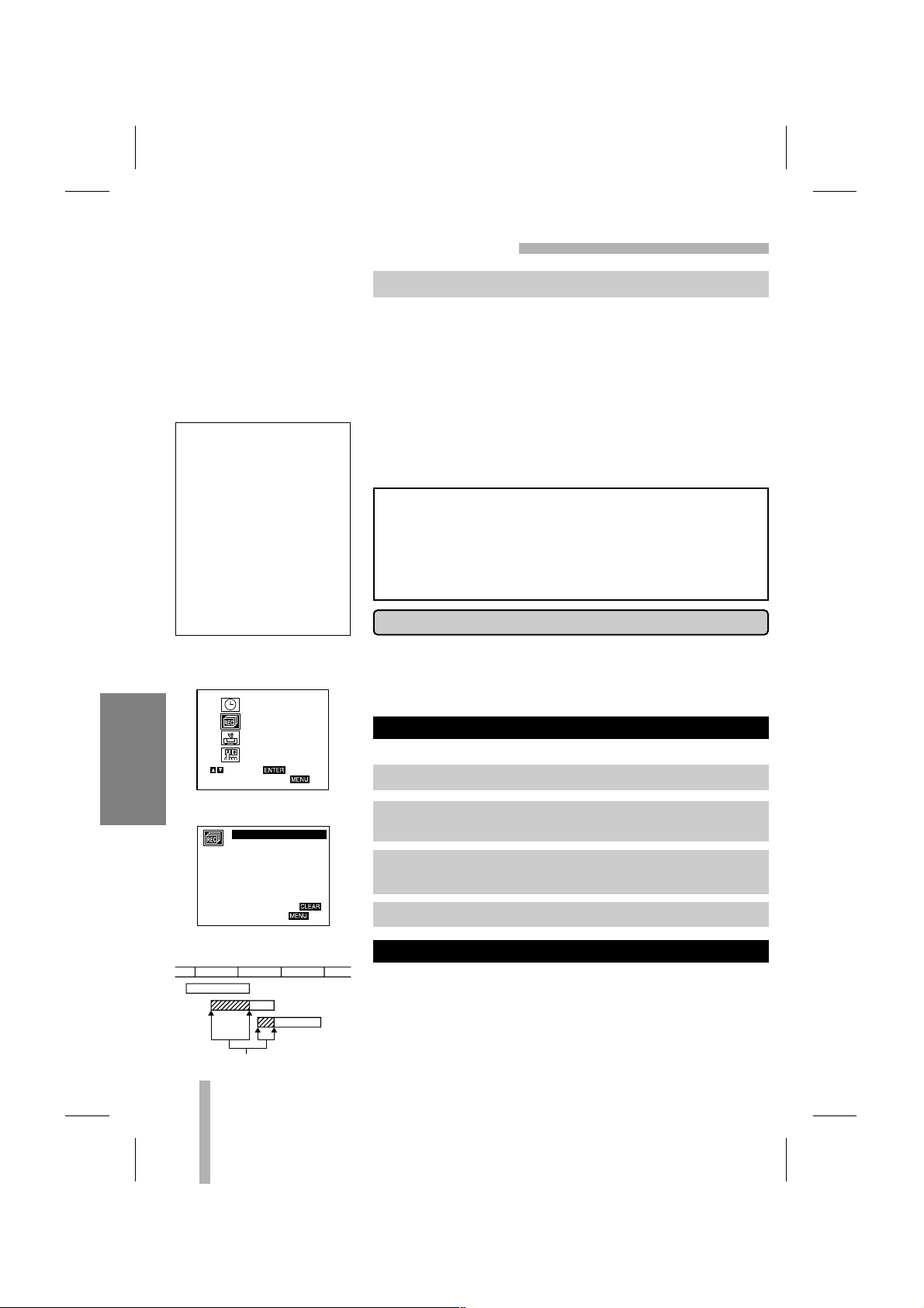
PREPARATION
SETTING THE ONSCREEN DISPLAY
The SETUP, clock setting, and timer recordings are accessed
conveniently with Onscreen Menu Displays that lead you
through each step. The following pages describe the Onscreen
selections to be set.
PREPARATION
• Turn on the power of both the VCR and TV.
• Be sure the TV is set to the VCR Output Channel (CH 3 or 4).
• If a direct VIDEO/AUDIO connection is made between the
VCR and the TV, set the TV’s source selector to VIDEO.
Your VCR allows remote control adjustment of several features.
CLOCK SET (page 20-21)
PROGRAM (page 26-28)
TUNING (page 17-18)
SETUP (page 16)
MENU SELECTION
MAIN MENU
MONTH : JANUARY
DAY : 1 MON
YEAR : 2001
TIME : 12 : 00 AM
SELECT
TO EXIT PRESS
ADJUST
AUTO CLOCK SET : ON
DAYLIGHT SAVING: AUTO
TIME ZONE: AUTO
CLOCK
PROGRAM
TUNING
SETUP
SELECT
TO EXIT PRESS
ENTER
SELECT
TO EXIT PRESS
ADJUST
PROGRAM 1
MONTH :
DAY :
START :
STOP :
CHANNEL :
SPEED :
REPEAT :
AUTO CHANNEL SET
TUNING BAND: TV
CH. ADD/DEL: CH. 2 ADD
SOURCE SELECT: TUNER
SELECT
TO EXIT PRESS
ADJUST
FUNCTION OSD : ON
LANGUAGE SELECT:ENGLISH
AUDIO MODE: HI-FI
BROADCAST TYPE: STEREO
AUDIO OUTPUT: STEREO
SELECT
TO EXIT PRESS
ADJUST
1 Press MENU and the MAIN menu will appear.
2 Select the desired menu with the
DD
or EEbutton and then
press ENTER.
123
456
789
0
MENU
CH
TRACK
POWER
Ad JUMP
TV/VCR
SLOW INPUT SP/SLP
EJECT
ENTER
CLK/COUNT
TV POWER
TV INPUT
CLEAR
PAUSE
STOP
REW FF
PLAY
REC
VOL TV CH TV CH
VOL
• The onscreens can be seen displayed for 3 minutes.
NOTE
Page 16

16
PREPARATION
SETTING THE SETUP MENU
MAIN MENU
SETUP MENU
Press DDor EEto choose a
desired item on the
SETUP menu. Then press
FF
or GGto choose a
desired setting.
The onscreen display of this VCR can be turned on or off.
The onscreen programming of this VCR can display in either
English, Spanish, or French.
The VCR has two separate audio playback systems, the high quality VHS Hi-Fi system and standard NORMAL mono system. The
same audio is generally recorded on both systems. The VHS Hi-Fi
system plays on separate (left and right) channels, and the NORMAL system plays monaural sound. The normal track is always
played so the cassette can be played on a VCR that does not have
VHS Hi-Fi.
Multichannel Television Sound (MTS) carries stereo and/or
Second Audio Program (SAP) bilingual signals. Set this display
to the desired position when both MTS stereo and SAP signals
are received. When only one of the MTS signal is received, the
VCR automatically selects the corresponding receiving mode
(Stereo or SAP) regardless of the selected position.
For normal operation, the display should be in the STEREO position. The VCR will then record a STEREO program when available,
and record a mono program IF the program NOT IN STEREO.
• For weak STEREO and/or SAP broadcasting, changing the
display to mono may give clearer sound.
Used during playback [when AUDIO MODE display (HI-FI/NORMAL) is in HI-FI position] for selecting the audio output signals from
the AUDIO OUT terminals (L ch and R ch), and VHF/UHF/CATV.
This display setting should normally be left in the stereo position,
so that when a stereo tape is played, the stereo sound will be
heard through the left and right channels. If a mono tape is
played and the audio output is set to stereo, the same mono
sound will be heard from both left and right channels.
AUDIO OUTPUT DISPLAY (STEREO/LEFT/RIGHT)
BROADCAST TYPE DISPLAY (STEREO/SAP/MONO)
AUDIO MODE DISPLAY
LANGUAGE SELECT
FUNCTION OSD
The AUDIO MODE is switched between HI-FI and NORMAL
by pressing
FF
or GG.
The BROADCAST TYPE is switched among STEREO, SAP,
and MONO by pressing
FF
or GG.
The AUDIO OUTPUTis switched among STEREO, LEFT, and
RIGHT by pressing
FF
or GG.
The LANGUAGE SELECT is switched among ENGLISH,
SPANISH and FRENCH by pressing
FF
or GG.
The FUNCTION OSD is switched between ON and OFF by
pressing
FF
or GG.
CLOCK
PROGRAM
TUNING
SETUP
SELECT
TO EXIT PRESS
FUNCTION OSD : ON
LANGUAGE SELECT:ENGLISH
AUDIO MODE: HI-FI
BROADCAST TYPE: STEREO
AUDIO OUTPUT: STEREO
SELECT
TO EXIT PRESS
ENTER
ADJUST
Page 17

17
PREPARATION
This VCR is equipped with a frequency synthesized tuner capable of receiving up to 181 channels. These include VHF channels 2-13, UHF channels 14-69 and CATV channels 1-125.
PREPARATIONS:
• Connect the VCR to the desired type of antenna or cable TV
system, as shown in ANTENNATO VCR CONNECTIONS and
CABLE ANTENNA(CATV) CONNECTION (pages 7-9).
• Switch on the power to the VCR and TV.
• Set the TV to the match the VCR output channel (CH 3 or 4).
Press
FF
or GGrepeatedly to switch between TUNER and LINE.
The tuner will automatically cycle through all available channels
in the area and place them in the tuner’s memory.
• Remember, TV is for the air antenna reception, CATV is for
cable or wireless cable connection.
Use CH/TRACK (▲/▼) or CHANNEL (▲/▼) on the front panel
to cycle the VCR through the channels in memory.
AUTO CHANNEL PROGRAMMING
CHANNEL SELECTION
1 Press MENU and the MAIN menu will appear.
2 Press
DD
or EEto select the TUNING menu, then press
ENTER. The TUNING menu will appear.
3 Press
EE
to choose the SOURCE SELECT item, then press
FF
or GGto select TUNER.
4 Press
DD
or EEto choose the AUTO CHANNEL SET item,
then press
FF
or GGto set the channel.
5 After the AUTO CHANNEL SET PROCEEDING is complete,
make sure the TUNING BAND is set appropriately (TV or
CATV) by pressing
DD
or EEand choosing the correct TUNING
BAND (TV or CATV) by pressing
FF
or GGusing the TUNING
menu.
6 Press MENU to return to the TV screen.
MENU
CH
TRACK
ENTER
CLK/COUNT
TV POWER
TV INPUT
CLEAR
PAUSE
STOP
REW FF
PLAY
VOL TV CH TV CH
VOL
CLOCK
PROGRAM
TUNING
SETUP
SELECT
TO EXIT PRESS
AUTO CHANNEL SET
TUNING BAND: TV
CH. ADD/DEL: CH. 2 ADD
SOURCE SELECT: TUNER
SELECT
TO EXIT PRESS
AUTO CHANNEL SET
TUNING BAND: TV
CH. ADD/DEL: CH. 2 ADD
SOURCE SELECT: TUNER
SELECT
TO EXIT PRESS
AUTO CHANNEL SET
TUNING BAND: TV
CH. ADD/DEL: CH. 2 ADD
SOURCE SELECT: TUNER
SELECT
TO EXIT PRESS
AUTO CHANNEL SET
PROCEEDING
CHANNEL 13
ENTER
ADJUST
ADJUST
ADJUST
TO EXIT PRESS
AUTO CHANNEL SET
TUNING BAND: TV
CH. ADD/DEL: CH. 2 ADD
SOURCE SELECT: TUNER
SELECT
TO EXIT PRESS
ADJUST
Page 18

18
PREPARATION
CHANNEL SELECTION (Cont’d)
You don’t need to disconnect the VCR from the TV to watch TV
separately. When the VCR’s power is OFF, or when the VCR’s
power is ON and the TV/VCR selector is set to TV, the TV will
operate as if it were connected directly to the antenna or cable.
• The power cord must be plugged into an AC outlet.
• To view or record cable TV programs with the VCR, the VCR’s
TUNING BAND item must be set to CATV (TUNING menu).
• Do not place the VCR directly on top of the TV. This may
cause interference in the picture and sound (of the VCR) during the recording or playback mode. If this interference
occurs, locate the VCR away from the TV.
Switch on the TV and set it to the
channel that you wish to watch.
Set POWER to OFF.
This feature allows you to add or erase channels from memory
manually.
Repeat steps 3 and 4 to add or erase channels.
TO ADD OR ERASE CHANNELS FROM MEMORY
VIEWING TV ONLY
MAIN MENU
TUNING MENU
1 Press MENU and the MAIN menu will appear.
2 Press
DD
or EEto select the TUNING menu, then press
ENTER. The TUNING menu will appear.
3 Press
EE
to choose the CH. ADD/DEL item. Press FFor GGto
select a channel to add or erase.
4 Press ENTER to add or erase the channel.
5 Press MENU to return to the TV screen.
CLOCK
PROGRAM
TUNING
SETUP
SELECT
TO EXIT PRESS
ENTER
AUTO CHANNEL SET
TUNING BAND: TV
CH. ADD/DEL: CH. 2 ADD
SOURCE SELECT: TUNER
ADD/DELETE
SELECT
TO EXIT PRESS
ADJUST
STOP/ EJECTPOWER
CHANNEL
NOTES
Page 19

19
PREPARATION
VIDEO CASSETTE TAPES
This VCR will operate with any video cassette which has
the mark. The table below shows the recording/playback
time of VHS cassettes when they are used in the SP, LP and
SLP speeds. (LP speed is for playback only.)
• Do not expose video cassettes to extreme heat, high humidity, or strong magnetic fields.
• Do not tamper with the cassette mechanism.
• Do not touch the tape with your fingers.
• Always store an unused cassette in its case.
Hold the cassette with the arrow side up (top). Insert the
cassette gently into the slot in the direction of the arrow (on the
cassette) until the loading mechanism automatically pulls the
cassette into the unit. Make certain that the cassette is inserted
correctly.
• If the cassette is not loaded correctly, the VCR will eject the
cassette automatically after approximately 3 seconds.
Press STOP/EJECT twice or press EJECT on the remote control. The cassette will be ejected automatically . After the cassette
is visible in the tape slot, pull it out to remove it.
• Unloading the cassette is possible only when the power cord
is connected to the wall outlet.
• The cassette can be ejected when STOP/EJECT is pressed,
even if the VCR’s power is OFF.
UNLOADING
LOADING
WHEN HANDLING VIDEO CASSETTES
TYPE
T-60 T-120 T-160
SPEED
SP MODE 60 mins. 120 mins. 160 mins.
LP MODE 120 mins. 240 mins. 320 mins.
SLP MODE 180 mins. 360 mins. 480 mins.
To prevent accidental erasure, remove the tab after
recording.
To record again cover the
hole with vinyl tape.
SAFETY TAB
Page 20

20
PREPARATION
SETTING THE CLOCK
MENU
CH
TRACK
ENTER
CLK/COUNT
TV POWER
TV INPUT
CLEAR
PAUSE
STOP
REW FF
PLAY
VOL TV CH TV CH
VOL
PREPARATION
• Turn on the power of both the VCR and TV.
• Be sure the TV is set to the VCR Output Channel (CH 3 or 4).
• If a direct VIDEO/AUDIO connection is made between the
VCR and the TV, set the TV’s source selector to VIDEO.
The VCR gives you two ways to set the time and date: the Auto
Clock Feature or manually. The Auto Clock Feature enables the
VCR to set up the clock when the VCR is turned off.
The Auto Clock Set feature is set to ON at the factory. In the ON
setting, the VCR looks for a channel carrying XDS (Extended
Data Services) information. XDS updates the clock using the
Coordinated Universal Time.
If you choose AUTO, the VCR sets the clock using the DSTinformation broadcast in the signal (channel).
If you choose ON, the VCR sets the clock when the Daylight
Saving Time is started and ended.
If “AUTO” is selected as the time zone, the VCR sets the clock
using the first Coordinated Universal Time information it finds in
a broadcast signal.
AUTO CLOCK SET
• The clock uses the 12-hour system. (Be sure to set AM and
PM correctly.)
• The buttons for setting the clock are on the remote control.
• An illogical date will not be accepted (for example:
February 30).
• The initial Clock Setting is JANUARY 1, 2001, 12:00 AM.
MAIN MENU
CLOCK SET MENU
CLOCK
PROGRAM
TUNING
SETUP
SELECT
TO EXIT PRESS
ENTER
1 Press MENU and the MAIN menu will appear.
2 Press
DD
or EEto choose the CLOCK menu.
Press ENTER and the CLOCK menu will appear.
3 Press
EE
to choose the AUTO CLOCK SET item.
Press
FF
or GGto choose ON.
6 Press MENU when finished.
7 Turn off the VCR and the auto clock setting works.
Things to know before starting
There are cases that TV
station does not send or
send wrong date and/or
time information and VCR
set the incorrect time
accordingly.
In this case we recommend
that you set the clock
manually.
4 Press
EE
to choose the DAYLIGHT SAVING item.
Press
FF
or GGto choose AUTO, ON or OFF.
5
PressEEto choose the TIME ZONE item.
Press
FF
or GGto choose the correct time zone (AUTO, ESTERN,
CENTRAL, MOUNTAIN, PACIFIC, ALASKA or HAWAII).
MONTH : JANUARY
DAY : 1 MON
YEAR : 2001
TIME : 12 : 00 AM
AUTO CLOCK SET : ON
DAYLIGHT SAVING: AUTO
TIME ZONE: AUTO
SELECT
TO EXIT PRESS
MONTH : JANUARY
DAY : 1 MON
YEAR : 2001
TIME : 12 : 00 AM
AUTO CLOCK SET : ON
DAYLIGHT SAVING: AUTO
TIME ZONE: AUTO
SELECT
TO EXIT PRESS
MONTH : JANUARY
DAY : 1 MON
YEAR : 2001
TIME : 12 : 00 AM
AUTO CLOCK SET : ON
DAYLIGHT SAVING: AUTO
TIME ZONE: AUTO
SELECT
TO EXIT PRESS
ADJUST
ADJUST
ADJUST
NOTE
Page 21

SETTING THE CLOCK (Cont’d)
21
PREPARATION
CLOCK SET MENU
Example: July 5, 2001 ; 2:15 AM
The day of the week will display automatically.
The “AUTO CLOCK SET” must set to “OFF”.
If set to "ON", an incorrect date and/or time will be entered again
when the VCR is turned off.
MANUAL CLOCK SET
MONTH : JANUARY
DAY : 1 MON
YEAR : 2001
TIME : 12 : 00 AM
SELECT
TO EXIT PRESS
ADJUST
AUTO CLOCK SET : ON
DAYLIGHT SAVING: AUTO
TIME ZONE: AUTO
1 Press MENU and the MAIN menu will appear.
2 Press
DD
or EEto choose the CLOCK menu.
Press ENTER and the CLOCK menu will appear.
3 Press
FF
or GGto choose the month.
4 Press
EE
to choose the DAY item.
Press
FF
or GGto choose the day.
5 Press
EE
to choose the YEAR item.
Press
FF
or GGto choose the year.
6 Press
EE
to choose the TIME item.
Press
FF
or GGto choose the time.
7 Press
EE
to choose the DAYLIGHT SAVING item. Press
FF
or GGto choose the ON or OFF.
8 Press MENU when finished.
MAIN MENU
CLOCK
PROGRAM
TUNING
SETUP
SELECT
TO EXIT PRESS
ENTER
MONTH : JULY
DAY : 5 THU
YEAR : 2001
TIME : 12 : 00 AM
AUTO CLOCK SET : OFF
DAYLIGHT SAVING: AUTO
TIME ZONE: AUTO
SELECT
TO EXIT PRESS
MONTH : JULY
DAY : 5 THU
YEAR : 2001
TIME : 12 : 00 AM
AUTO CLOCK SET : OFF
DAYLIGHT SAVING: AUTO
TIME ZONE: AUTO
SELECT
TO EXIT PRESS
MONTH : JULY
DAY : 5 THU
YEAR : 2001
TIME : 2 : 15 AM
AUTO CLOCK SET : OFF
DAYLIGHT SAVING: AUTO
TIME ZONE: AUTO
SELECT
TO EXIT PRESS
MONTH : JULY
DAY : 5 THU
YEAR : 2001
TIME : 2 : 15 AM
AUTO CLOCK SET : OFF
DAYLIGHT SAVING: ON
TIME ZONE: AUTO
SELECT
TO EXIT PRESS
ADJUST
ADJUST
ADJUST
ADJUST
NOTE
Page 22

22
PLAYBACK
NORMAL PLAYBACK
PREPARATION
• Turn on the TV.
• Be sure the TV is set to the VCR Output Channel (CH 3 or 4).
• If a direct VIDEO/AUDIO connection is made between the
VCR and the TV, set the TV’s source selector to VIDEO.
The indicator will light and the VCR will power-up
automatically.
• Make sure that the TIMER indicator in the VCR indicator panel
is not lighted. If it is, press POWER once.
• If a tape without a safety tab is inserted the unit will start the
playback automatically.
The PLAY appears in the VCR indicator panel and TV screen .
• It is not necessary to select the tape speed for playback. It will
be automatically selected by the VCR.
• In playback, the TV/VCR selector switches to VCR mode auto-
matically.
The STOP appears in the VCR indicator panel and TV screen.
• If the tape reaches the end before STOP is pressed, the VCR
will automatically stop, rewind, eject, and it will turn itself off.
AUTO TRACKING
The automatic tracking function adjusts the picture to remove
snow or streaks.
The AUTO TRACKING function works in the following cases:
• A tape is played back for the first time.
• Tape speed (SP, LP, SLP) changes.
• Streaks or snow appear because of scratches on the tape.
MANUAL TRACKING
If noise appears on the screen during playback, press either
CH/TRACK (
DD/EE
) on the remote control or CHANNEL (DD/EE) on
the front panel until the noise on the screen is reduced.
• In case of vertical jitter, adjust these controls very carefully.
• Tracking is automatically reset to normal when the tape is
ejected or the power cord is unplugged for more than 3
seconds.
TRACKING CONTROL
NORMAL PLAYBACK
1 Insert a prerecorded video cassette.
2 Press PLAY once.
3 Press STOP to stop playback.
123
456
789
0
MENU
CH
TRACK
POWER
Ad JUMP
TV/VCR
SLOW INPUT SP/SLP
EJECT
ENTER
CLK/COUNT
TV POWER
TV INPUT
CLEAR
PAUSE
STOP
REW FF
PLAY
REC
VOL TV CH TV CH
VOL
Page 23

23
PLAYBACK
SPECIAL EFFECTS PLAYBACK
These special effects are available during playback.
During PLAYBACK mode...
Still picture will appear on the TV screen.
• If a still picture vibrates vertically, stabilize it by pressing
CH/TRACK (DD/EE) on the remote control.
• If the VCR is left in the STILL mode for more than 5 minutes,
the VCR will automatically enter the STOP mode to
protect the tape and video heads.
This function lets you quickly and visually search for a desired
tape section in either direction: forward and reverse.
During PLAYBACK mode...
The VCR will be activated in the SEARCH mode and SCH or
SCH- will appear on the VCR indicator panel.
• If the VCR is left in the SEARCH mode for more than 3 minutes, the VCR will automatically enter the PLAYmode, to protect the tape and video heads.
During PLAYBACK mode...
The tape will be played back at a speed 1/19 times slower than
the normal speed.
• During slow playback, CH/TRACK (▲/▼) on the Remote
Control can be used to minimize noise bands.
• When the slow mode continues for more than 30 seconds, the
VCR will automatically change to PLAYBACK mode.
USING THE SLOW MOTION FEATURE
VISUAL SEARCH FUNCTION
TO WATCH A STILL (or Frame Advance) PICTURE
1 Press PAUSE or PAUSE/STILL on the front panel.
3 To continue normal playback, press PLAY.
1 Press desired search button (FF or REW).
2 To continue normal playback, press PLAY.
2 Press PAUSE repeatedly to advance the video picture one
frame at a time while viewing a still picture.
123
456
789
0
MENU
CH
TRACK
POWER
Ad JUMP
TV/VCR
SLOW INPUT SP/SLP
EJECT
ENTER
CLK/COUNT
TV POWER
TV INPUT
CLEAR
PAUSE
STOP
REW FF
PLAY
REC
VOL TV CH TV CH
VOL
1 Press SLOW.
2 Press PLAY to return to normal playback speed or press
STOP to stop tape movement.
Page 24

24
PLAYBACK
123
456
789
0
MENU
CH
TRACK
POWER
Ad JUMP
TV/VCR
SLOW INPUT SP/SLP
EJECT
ENTER
CLK/COUNT
TV POWER
TV INPUT
CLEAR
PAUSE
STOP
REW FF
PLAY
REC
VOL TV CH TV CH
VOL
123
456
789
0
MENU
CH
TRACK
POWER
Ad JUMP
TV/VCR
SLOW INPUT SP/SLP
EJECT
ENTER
CLK/COUNT
TV POWER
TV INPUT
CLEAR
PAUSE
STOP
REW FF
PLAY
REC
VOL TV CH TV CH
VOL
SPECIAL EFFECTS PLAYBACK (Cont’d)
SPECIAL EFFECTS PLAYBACK NOTES:
• Horizontal lines (noise bars) will appear on the TV screen.
This is normal.
• The audio is automatically muted during special effect
modes, so there is no sound during search.
• During the high-speed picture search modes, a short period is
needed to stabilize tape speed when re-entering the PLAY
mode. Slight interference may be observed during this period.
This is useful for skipping commercials or short program
segments.
The tape will fast forward picture search through 30 seconds of
recording.
The skipping time can be extended by pressing Ad JUMP.
Subsequent presses result in advancing the fast forward picture
search time by 30-second increments (maxmam 3 minutes).
Ad JUMP (Advertisement Jump)
1 Press Ad JUMP during the PLAYBACK mode.
2 When the search is completed, the VCR will go into PLAY-
BACK mode automatically.
This VCR features full automatic playback and rewind.
Load a cassette (with the safety tab removed).
• The power turns on automatically and playback begins.
• At the end of the tape, the VCR stops, then rewinds.
• The cassette is ejected after rewinding and turn itself off automatically.
This feature is especially helpful when you finish watching a tape. Press STOP, REW, and
POWER. The VCR will rewind the tape and turn itself off automatically.
1. Press STOP when you finish watching a tape.
2. Press REW to rewind the tape.
3.
Press POWER during the REWIND mode, the VCR will enter the AUTO POWER SHUT-OFF mode.
4. The REW will flash on the VCR indicator panel.
5. After tape is rewound, VCR will turn off automatically.
AUTO POWER SHUT-OFF FUNCTION
AUTO PLAY SYSTEM
LOAD
TAPE
AUTO
REWIND
AUTO
POWER
OFF
AUTO
EJECT
AUTO
PLAY
STOP
REWIND
AUTO
POWER
OFF
POWER
REW
Page 25

25
NORMAL RECORDING
PREPARATION
• Turn on the power of both the VCR and TV.
• Be sure the TV is set to the VCR Output Channel (CH 3 or 4).
• If a direct VIDEO/AUDIO connection is made between the
VCR and the TV, set the TV’s source selector to VIDEO.
• If you are recording from another source via audio/video input
jacks (at the Rear), select the LINE by pressing INPUT.
• This VCR is not designed to record in LP mode.
Recording will start. (The REC will appear)
• If a cassette with no safety tab is loaded, the cassette will be
ejected automatically.
• If the tape reaches the end before STOP is pressed, the VCR
will automatically stop, rewind, eject, and it will turn itself off.
During the RECORDING mode...
The RECP will show on the VCR indicator panel.
• After 5 minutes in pause mode, the tape will be stopped
automatically to protect the tape and the video heads.
The VCR indicator disappears.
To record one TV program while watching another
To PAUSE the recording
1 Insert the video cassette that the safety tab is in place.
2 Select the desired channel by using CH/TRACK (▲/▼).
3 Set the desired speed (SP or SLP) by pressing SP/SLP.
4 Set the MTS mode as desired (See page 16, 32).
5 Press REC once.
6 Press STOP to stop recording.
1 Press PAUSE or PAUSE/STILL on the front panel to pause
the tape.
2 When you want to continue recording, press PAUSE again
or press REC.
Always use PAUSE for
best results when making
changes during recording.
For example: To change
channels during recording,
first press PAUSE to put
the unit in pause mode.
Then select the desired
channel on the VCR, and
press PAUSE again to
resume recording.
1 Press TV/VCR to select the TV mode during recording.
2 Using the TV, select the channel to be viewed.
123
456
789
0
MENU
CH
TRACK
POWER
Ad JUMP
TV/VCR
SLOW INPUT SP/SLP
EJECT
ENTER
CLK/COUNT
TV POWER
TV INPUT
CLEAR
PAUSE
STOP
REW FF
PLAY
REC
VOL TV CH TV CH
VOL
RECORDING
Page 26

26
RECORDING
TIMER RECORDING
This VCR can be programmed to record up to 8 programs within a period of 1 year. For unattended recording, the timer needs
to know the channels to be recorded and the starting and ending times.
PREPARATION
• Turn on the power of both the VCR and the TV.
• Be sure the TV is set to the VCR output channel (3 or 4).
• Make sure the TUNING BAND in the TUNING menu is set
appropriately (TV or CATV) (see illustration left).
The PROGRAM menu will appear.
• If all programs have already been entered, FULLY PROGRAMMED message will appear for a moment and then
PROGRAM 1 will appear on the TV screen.
Example: JULY
• If you try to set the program timer before setting the clock,
PLEASE SET THE CLOCK appears for a moment and then
CLOCK menu appears on the TV screen. Set the time and
date before proceeding.
• The display contents will be automatically replaced by TV
programs after 3 minutes.
• Make sure a tape is in the VCR and the safety tab is in place
or the tape will be automatically ejected.
MAIN MENU
TUNING MENU
1 Press MENU and the MAIN menu will appear.
2 Press
DD
or EEto choose the PROGRAM menu.
3 Press ENTER to enter the PROGRAM menu.
4 Press
FF
or GGto choose the PROGRAM No. (1-8).
5 Press
EE
to choose the MONTH item.
Press
FF
or GGto choose the desired month.
Things to know before starting
MENU
CH
TRACK
ENTER
CLK/COUNT
TV POWER
TV INPUT
CLEAR
PAUSE
STOP
REW FF
PLAY
VOL TV CH TV CH
VOL
AUTO CHANNEL SET
TUNING BAND: TV
CH. ADD/DEL: CH. 2 ADD
SOURCE SELECT: TUNER
SELECT
TO EXIT PRESS
ADJUST
SELECT
TO EXIT PRESS
PROGRAM 1
MONTH :
DAY :
START :
STOP :
CHANNEL :
SPEED :
REPEAT :
SELECT
TO EXIT PRESS
PROGRAM 1
MONTH : JULY
DAY :
START :
STOP :
CHANNEL :
SPEED :
REPEAT :
SELECT
TO EXIT PRESS
CLOCK
PROGRAM
TUNING
SETUP
ADJUST
ADJUST
ENTER
Page 27

27
RECORDING
TIMER RECORDING (Cont’d)
Example: 6 FRI
Example: 6:00 PM
Example: 7:30 PM
Example: CH 4
Cable Users: If you have CABLE TV and used Cable Box in
Cable Antenna Connections (pages 8-9), using a cable box converter, you must set the channel in this step to match the cable
box output channel (usually CH 3 or 4). Change channels on the
cable box instead of with the VCR.
Example: SP
• The AUTO mode determines how much tape is left and
switches speed from SP to SLP, if necessary, to complete
recording the program. There will be some picture and sound
distortion at the point of the speed change.
Example: ONCE
If the input data is wrong, press
DD
to select the data and
correct it by pressing
FF
or GG.
ONCE event....for recording up to 8 programs on a single day
or over the days within a period of 1 year.
WEEKLY event....for recording up to 8 programs on a certain
day of every week.
DAILY event....for recording up to 8 programs at the same
time(s) Monday through Friday.
6 Press
EE
to choose the DAY item.
Press
FF
or GGto choose the desired day.
7 Press
EE
to choose the START item.
Press
FF
or GGto choose the desired start time.
8 Press
EE
to choose the STOP item.
Press
FF
or GGto choose the desired stop time.
9 Press
EE
to choose the CHANNEL item.
Press
FF
or GGto choose the desired channel (Channel or
LINE).
10
PressEEto choose the SPEED item.
Press
FF
or GGto choose the desired tape speed (AUTO, SP
or SLP).
11
PressEEto choose the REPEAT item.
Press
FF
or GGto choose the desired repeat (ONCE,
WEEKLY, or DAILY).
PROGRAM 1
MONTH : JULY
DAY : 6 FRI
START :
STOP :
CHANNEL :
SPEED :
REPEAT :
SELECT
TO EXIT PRESS
PROGRAM 1
MONTH : JULY
DAY : 6 FRI
START : 6:00 PM
STOP :
CHANNEL :
SPEED :
REPEAT :
SELECT
TO EXIT PRESS
PROGRAM 1
MONTH : JULY
DAY : 6 FRI
START : 6:00 PM
STOP : 7:30 PM
CHANNEL :
SPEED :
REPEAT :
SELECT
TO EXIT PRESS
PROGRAM 1
MONTH : JULY
DAY : 6 FRI
START : 6:00 PM
STOP : 7:30 PM
CHANNEL : 4 TV
SPEED : AUTO
REPEAT : ONCE
SELECT
TO EXIT PRESS
ADJUST
ADJUST
ADJUST
ADJUST
PROGRAM 1
MONTH : JULY
DAY : 6 FRI
START : 6:00 PM
STOP : 7:30 PM
CHANNEL : 4 TV
SPEED : SP
REPEAT : ONCE
SELECT
TO EXIT PRESS
PROGRAM 1
MONTH : JULY
DAY : 6 FRI
START : 6:00 PM
STOP : 7:30 PM
CHANNEL : 4 TV
SPEED : SP
REPEAT : ONCE
SELECT
TO EXIT PRESS
ADJUST
ADJUST
Page 28
28
RECORDING
TIMER RECORDING (Cont’d)
• If the program preset time is past, the PAST TIME PROGRAMMED message will appear on the TV screen. Return to
the incorrect program and program it with the correct time.
• If you had entered a past date, the timer recording will be performed on that date of the next year.
• Additional programs may be entered by repeating steps 1-12.
Cable Users: If your cable hookup is via a TV converter box, you
can program multiple recordings only on the converter box output channel. This is because the converter determines what
channel you view through your VCR.
You can clear the timer recording by pressing POWER
during timer recording.
Programming can be checked whenever the VCR is turned on.
If the recording start and end times of preset programs overlap
on the same day (see the example and diagram left), program
number 2 will not be recorded until program number 1 is finished.
The first part of program number 2 will not be recorded. The
same thing will happen to program number 3.
PROGRAM PRIORITY
CHECKING (ERASING) THE TIMER PROGRAM
The VCR must be off for a timer recording to take place!
1 Press MENU and the MAIN menu will appear.
2 Press
DD
or EEto choose the PROGRAM menu.
Press ENTER and the PROGRAM menu will appear.
3 Press
FF
or GGto select a program you want to check or
erase. If you want to erase the program, press CLEAR.
4 Press MENU to return to the TV screen.
12Press MENU, the program will be memorized at the VCR.
MAIN MENU
PROGRAM MENU
If you are finished programming and you want to set the VCR
to record the programs you have entered. A) MAKE SURE
YOU HAVE INSERTED A TAPE INTO THE VCR. B) YOU
MUST TURN OFF THE VCR BEFORE IT WILL RECORD
ANY TIMER PROGRAMS. (TIMER indicator lights). The
VCR is now set to record the preset programs.
If the power fails or the
VCR is unplugged from
the AC outlet, the correct
clock time and timer settings are kept in memory
for approximately 3 seconds. After 3 seconds,
the clock and program
timer must be reset
when power is restored.
Reset time according to
instructions.
CLOCK
PROGRAM
TUNING
SETUP
SELECT
TO EXIT PRESS
PROGRAM 1
MONTH : JULY
DAY : 6 FRI
START : 6:00 PM
STOP : 7:30 PM
CHANNEL : 4 TV
SPEED : SP
REPEAT : ONCE
TO ERASE PRESS
TO EXIT PRESS
ENTER
7:00 PM 8:00 PM 9:00 PM 10:00 PM
Prog No. 1
Prog No. 2
Prog No. 3
These portions will
not be recorded.
Page 29

29
RECORDING
INSTANT TIMER RECORDING
0H30M 1H00M 1H30M
0H00M 9H00M 8H30M
Length Display
(each press increases
recording by 30 minutes)
INSTANT TIMER RECORD
MENU
INSTANT TIMER RECORD
CHANNEL 2
SPEED SP
START NOW
LENGTH 0H30M
Instant Timer Recording allows you to make a recording easily of
a preset length without using the program timer.
PREPARATION
• Turn on the power of both the VCR and the TV.
• Be sure the TV is set to the VCR output channel (3 or 4).
• If a direct VIDEO/AUDIO connection is made between the
VCR and the TV, set the TV’s source selector to VIDEO.
The channel number appears on the TV screen and indicator panel.
• If you are recording from another source via audio/video input
jacks (at the Rear), select the LINE.
The tape speed will appear on the TV screen and indicator panel.
The menu as illustrated, will appear on the TV screen.
Recording will start. (The TIMER indicator will light)
At the end of recording the display will read 0H00, the VCR will
stop recording and shut off.
• During Instant Timer Recording, changing the channel on the
VCR will not be possible.
• You can stop the recording by pressing STOP .
Press REC once to check the recording time. The recalled
setting will automatically return to the TV screen after 6 seconds.
The recording time can be extended anytime by pressing REC.
Subsequent presses result in advancing the recording time by
30-minute increments.
• If you press PAUSE during instant timer recording, the VCR
will enter the normal recording mode.
• If the VCR is set to “0H00M”, the VCR goes to normal record-
ing mode.
TO EXTEND THE RECORDING TIME
CHECKING THE RECORDING TIME
1 Insert the video cassette that the safety tab is in place.
2 Select the desired channel by using CH/TRACK (▲/▼) or
number (0-9).
3 Set the TAPE SPEED item to desired speed (SP or SLP) by
pressing SP/SLP.
4 Press REC twice.
5 Press REC repeatedly to select the recording time length.
123
456
789
0
MENU
CH
TRACK
POWER
Ad JUMP
TV/VCR
SLOW INPUT SP/SLP
EJECT
ENTER
CLK/COUNT
TV POWER
TV INPUT
CLEAR
PAUSE
STOP
REW FF
PLAY
REC
VOL TV CH TV CH
VOL
NOTE
Page 30
30
RECORDING
DUBBING AND EDITING
AUDIO
LINE1(AUX1)
R
L
IN
IN
OUT
OUT
ANT.IN
VIDEO
CH.
34
VHF/UHF
/CATV
Camcorder:
Play
Another VCR: Play
Your VCR: Recording
OR
From
AUDIO and
VIDEO Output
From
AUDIO and
VIDEO Output
To AUDIO/VIDEO Inputs
1 Connect the camcorder ’s (or another VCR’s) A/V outputs to your VCR as illustrated above.
2 Set the input channel “LINE”. (Press INPUT to select LINE.)
3 Play the tape in the camcorder (or another VCR). If you have a TV attached to your VCR,
you can see the video playing.
4 When you desire recording to begin, press VCR’s REC once to start.
Before recording, please confirm the recording start position.
If you wish to edit or dub your camcorder (or another VCR) recordings to this VCR, the rear
(or Front) panel mounted Audio and Video (A/V) input jacks make the connections quick and
easy. The direct A/V jacks will also provide better picture results than using the RF jack on the
rear panel.
NOTE
Page 31

31
VHS Hi-Fi STEREO SYSTEM/MTS BROADCAST
This VCR is equipped with the VHS Hi-Fi audio sound system for
recording and playback. The information below gives a brief
description of Hi-Fi audio and how to record and play a tape in
the Hi-Fi audio mode.
A stereo TV with AUDIO/VIDEO input jacks or a stereo audio system is required for true stereo playback. To experience the full and
rich stereo sound available with Hi-Fi recorded tapes, we recommend the connection of this unit to a home stereo audio system.
(STEREO) POSITION: The left channel sound (L) is heard from
the left speaker and the right channel sound (R) is heard from
the right speaker.
(LEFT) POSITION: The left channel sound (L) is heard from both
speakers.
(RIGHT) POSITION: The right channel sound (R) is heard from
both speakers.
Adjust volume at your stereo system.
PLAYBACK WITH Hi-Fi STEREO AUDIO SOUND
1 Set the AUDIO MODE item to HI-FI on the SETUP menu .
2 Set the AUDIO OUTPUT item to STEREO position.
3 Insert a cassette and press PLAY.
To enjoy the Hi-Fi stereo system, you connect your VCR’s
AUDIO(R/L)/VIDEO OUT jacks to the AUDIO(R/L)/VIDEO
INPUT jacks on back your TV (or another A/V system) using
the A/V cable.
ADDITIONAL INFORMATION
FUNCTION OSD : ON
LANGUAGE SELECT:ENGLISH
AUDIO MODE: HI-FI
BROADCAST TYPE: STEREO
AUDIO OUTPUT: STEREO
SELECT
TO EXIT PRESS
FUNCTION OSD : ON
LANGUAGE SELECT:ENGLISH
AUDIO MODE: HI-FI
BROADCAST TYPE: STEREO
AUDIO OUTPUT: STEREO
SELECT
TO EXIT PRESS
ADJUST
ADJUST
Page 32

32
VHS Hi-Fi STEREO SYSTEM/MTS BROADCAST (Cont’d)
This VCR will decode MTS stereo and bilingual (SAP) off-the-air
broadcast sound signals. It also decodes stereo TV sound from
local cable companies, as long as they operate on assigned
cable frequencies and use the EIA-recommended MTS
stereo/bilingual TV sound system.
MULTICHANNEL TV SOUND INDICATOR (MTS)
Shows Onscreen as illustrated on the left when ENTER is pressed.
• One or both of the indicators will light, depending on the MTS
broadcast.
If only the STEREO appears on the TV screen.
The VCR can record in stereo onto the VHS Hi-Fi audio tracks
when the BROADCAST TYPE item is in the STEREO position.
The VCR will also record mono audio onto the mono audio track.
If only the SAP appears on the TV screen.
Select the BROADCAST TYPE item to SAP.
If both the STEREO/SAP appears on the TV screen
Use the BROADCAST TYPE item to select the desired recording mode (STEREO or SAP).
Some stations transmit a Second Audio Program, which is used
for a second language or additional information. When the station broadcasts a Second Audio Program, follow the procedure
below to record the SAP.
You are now recording the program you see and hear on the TV.
SAP (Second Audio Program) RECORDING
MTS (Multi-Channel TV Sound)
1 Insert a video cassette that the safety tab is in place.
2 Set the BROADCAST TYPE item to SAP (SETUP menu).
Do this if only the SAP appears on the TV screen or you
know the program will use the SAP.
3 Set the desired speed (SP or SLP) by pressing SP/SLP.
4 Select the desired channel. The SAP should appear on the
TV screen.
5 Press REC once
6 Press STOP to stop recording.
CH 4
STEREO/SAP
STEREO
Lights up when a stereo
broadcast is being
received.
SAP
Lights up when a SAP
BILINGUAL broadcast is
being received.
TV screen
ADDITIONAL INFORMATION
FUNCTION OSD : ON
LANGUAGE SELECT:ENGLISH
AUDIO MODE: HI-FI
BROADCAST TYPE: SAP
AUDIO OUTPUT: STEREO
SELECT
TO EXIT PRESS
ADJUST
Page 33

33
ADDITIONAL INFORMATION
TAPE COUNTER MEMORY FEATURE
Shows length of tape run in hours, minutes, and seconds (refer
to the left). Press CLK/COUNT to select the real-time counter
display.
Every press of CLK/COUNT changes the TV screen as illustrated left.
• Counter changes to 0:00:00 when the cassette is ejected.
• The real-time counter does not operate when nothing is
recorded on the tape.
• The real-time counter will not work when the tape is not inserted.
This is useful if there is a section of tape you want to view immediately after recording or if you want to return to the same point
several times.
The tape automatically stops when the tape counter returns to
about “0:00:00”.
COUNTER MEMORY FUNCTION
REAL-TIME COUNTER
1 Begin recording or playing a tape.
2 Press CLK/COUNT repeatedly to display the real-time
counter appears on the TV screen.
3 At the point that you want locate later, reset the real-time
counter to 0:00:00 by pressing CLEAR.
4 Continue to play or record.
5 Press STOP when recording or playback finishes.
6 Press REW.
123
456
789
0
MENU
CH
TRACK
POWER
Ad JUMP
TV/VCR
SLOW INPUT SP/SLP
EJECT
ENTER
CLK/COUNT
TV POWER
TV INPUT
CLEAR
PAUSE
STOP
REW FF
PLAY
REC
VOL TV CH TV CH
VOL
2:15 AM
0:05:25
REM 1:07
Indicator Panel
TV Screen
TAPE REMAINING
This function allows the time of the remaining tape to be displayed during recording or playback.
The remaining tape length indicator may not be displayed
correctly depending on the condition of the tape and the kind of
the tape (T-140, T-160, or T-210 etc)
CLOCK
COUNTER
REMAINING TIME
Indicator Panel TV Screen
Press CLK/COUNT until the REM indicator displays on the TV
screen during recording or playback.
REM 1:07
NOTE
Page 34

34
ADDITIONAL INFORMATION
EDITING A RECORDING
OPERATING HINTS
The program material to be recorded will appear on the television.
The new program material will directly follow the previously
recorded material. This feature is especially helpful during camcorder-to-VCR dubbing use so each segment of the recording
becomes a continuous program.
• In manual recording, Timer recording, Instant Timer
Recording, playback, or fast forward modes, the VCR automatically starts rewinding the tape at the end of the tape. The
cassette will stop at the beginning of the tape and be ejected, and the VCR will turn itself off.
• After you have finished using the VCR, rewind, eject, and
remove the cassette. Place the cassette in its protective
sleeve to protect it from dust. It is not necessary to rewind the
cassette before removing it, but if you do, it will be ready to
play or record the next time you use it.
• Be sure the VCR Channel Selector is on the correct channel
you wish to record. The channel that is being recorded can
always be checked by setting the television on the VCR
channel (3 or 4) and pressing the TV/VCR selector to turn
the VCR’s VCR indicator on.
• Do not attempt to hook up more than one television set to the
VCR for either recording or playback.
1 Press PLAY and watch the program until you reach the exact
point where you want the new recording to start.
2 Press PAUSE.
3 Press REC once.
4 When you wish to start recording, press PAUSE again.
123
456
789
0
MENU
CH
TRACK
POWER
Ad JUMP
TV/VCR
SLOW INPUT SP/SLP
EJECT
ENTER
CLK/COUNT
PAUSE
STOP
REW FF
PLAY
REC
VIDEO HEAD CLEANING
• Whenever a video cassette is inserted into or ejected from
this unit the video head is automatically cleaned.
• However, it is possible that the heads may become clogged
when playing an old or damaged tape. If the image on your
screen resembles the picture on the left while playing back a
tape, the heads may require cleaning.
• To clean the heads, obtain a head cleaning tape from your
local video dealer. Follows the instructions that come with the
cleaning tape, as excessive use can shorten head life.
Page 35

35
ADDITIONAL INFORMATION
TROUBLESHOOTING
• Load cassette in direction indicated by arrow on cassette.
• A cassette is already in the VCR.
• Check if the VCR indicator panel is lit. If not, make sure power
cord is plugged in.
• If the indicator flashes, press POWER again.
• Press TV/VCR to select the VCR mode.
• Set the television to the same channel selected on the VCR
OUTPUT CHANNEL SELECT SWITCH. (CH3 or CH4).
• Adjust the Tuning Control on the television to obtain the best
picture.
• The cassette has had the safety tab removed. Stick a piece of
cellophane tape over the safety tab hole or select a different
cassette.
• Set the television to the VCR channel (3 or 4) depending upon
the selected channel on the back of the VCR. (Output Channel).
• Try a different cassette tape.
• The heads may require cleaning.
• Take VCR to a qualified Service Center for service.
• Adjust fine tuning knob on television set to obtain best picture.
• Adjust the tracking control.
• Take VCR to Service Center for service.
• Weak or dead batteries.
• Do not block sensor.
• Reset time according to instructions. Power has been interrupted.
• Setup recording time according to instructions.
• Be sure the AM-PM display is correct.
• The cassette has had the safety tab removed. Stick a piece of cello-
phane tape over the safety tab hole or select a different cassette.
• Insert a cassette.
• The TV station sent the wrong XDS infomation. Use the Manual
Clock Set procedure on page 21.
Cassette cannot be inserted.
No picture appears on TV
screen.
A picture appears on TV screen
but is not clear.
The VCR will not go into the
recording mode, even when
REC is pressed.
No picture appears on television
screen when PLAY is pressed.
No picture, but audio is clear.
Interference on playback
picture.
The VCR cannot be remotely
controlled or the remote control
has short range.
“--:--” appears on the indicator
panel.
VCR does not start at preset
record starting time.
The tape is ejected in the timer
mode.
indicator flashes.
The Auto Clock Setup procedure
enters the wrong date and/or time.
SYMPTOM CHECK POINT & CORRECTION
Page 36

36
ADDITIONAL INFORMATION
Head System Four head helical scan azimuth system
Power Source AC 120V, 60Hz
Power Consumption Approx. 15 Watts
Dimensions (WxHxD) 360 x 94.5 x 230 mm (14.3” x 3.8” x 9.2”)
Operating Temperature 5 °C~35 °C (41 °F~95 °F)
Operating Humidity Less than 80% RH
Timer 12-hour display type with AM, PM
Weight Approx. 3.2 kg (7 lbs)
Tape Speed (SP) 33.35 mm/sec
(LP) 16.67 mm/sec
(SLP) 11.12 mm/sec
Tape Width 12.7 mm
Maximum Recording Time (SP) 2 HOURS (T-120)
(SLP) 6 HOURS (T-120)
8 HOURS (T-160)
Rewind Time about 3 minutes (T-120)
Antenna (UHF) 75 ohms
(VHF) 75 ohms
VHF Output Signal Channel 3 or 4 (Switchable)
Channel Coverage (VHF) 2-13
(UHF) 14-69
(CATV) 1-125 (4A, A-W, W+1~W+84, A-5~A-1)
Video Signal System EIA Standard (525 lines, 60 fields)
NTSC type color signal
Input 1.0 Vp-p 75 ohms unbalanced
Output 1.0 Vp-p 75 ohms unbalanced
Signal to Noise Ratio More than 43 dB (SP mode)
FM audio
Frequency Range 20Hz to 20kHz
Dynamic Range More than 83 dB
Channel Separation More than 55 dB
Conventional audio
Input (LINE) -6.0 dBm more than 47 kohms
Output (LINE) -6.0 dBm less than 1.0 kohms
S/N Ratio More than 43 dB (SP mode)
Frequency Range 200 Hz to 10kHz (SP mode)
* Designs and specifications are subject to change without notice.
* Weight and dimensions shown are approximate.
AUDIO
VIDEO
TUNER
GENERAL
SPECIFICATIONS
 Loading...