

SANYO FP215 Datasheet
SANYO Electric Co.,Ltd. Semiconductor Bussiness Headquaters
TOKYO OFFICE Tokyo Bldg., 1-10, 1 Chome, Ueno, Taito-ku, TOKYO, 110-8534 JAPAN
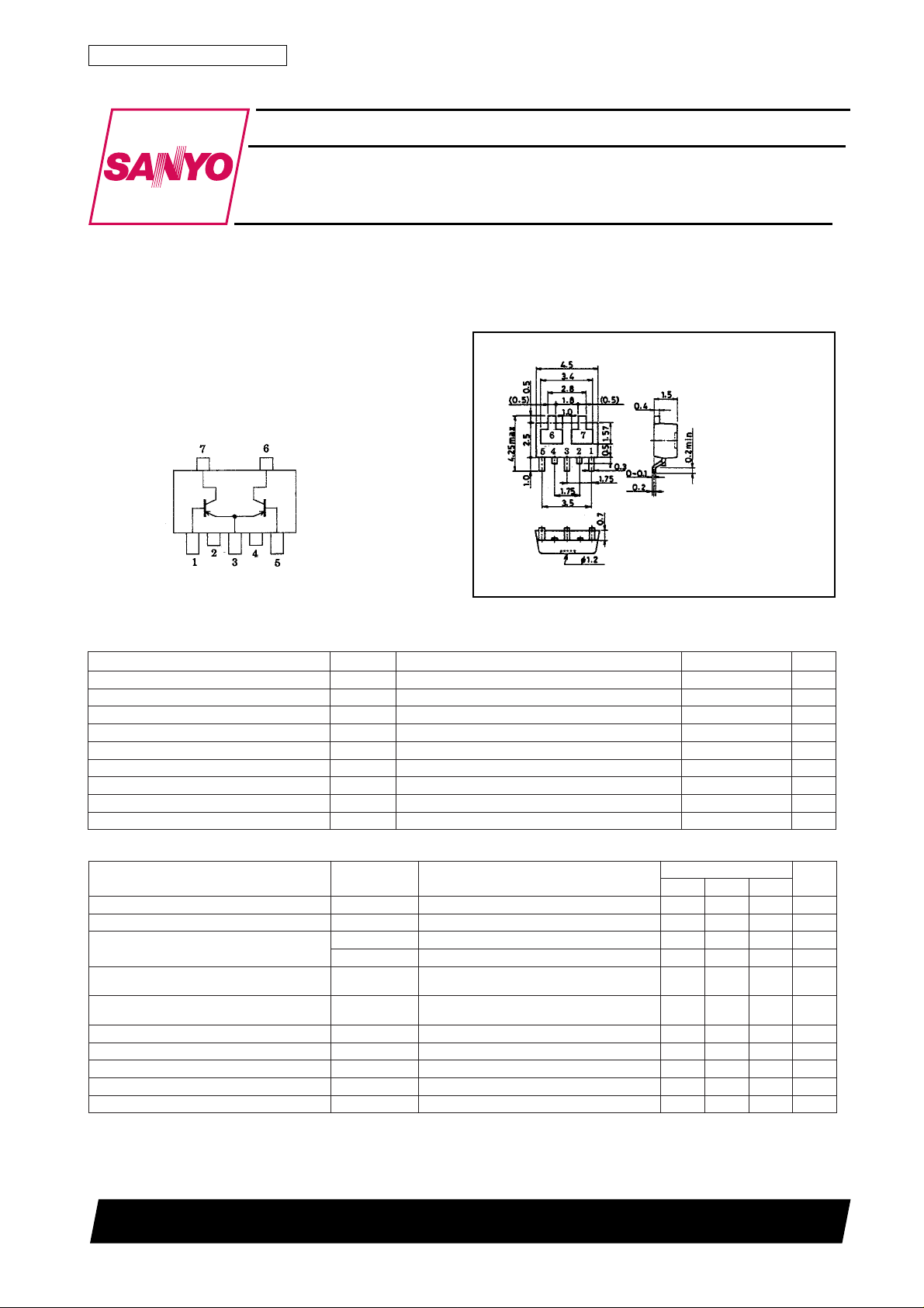
PNP Epitaxial Planar Silicon Composite Transistors
High-Frequency Amp,
Differential Amp Applications
Ordering number:EN4698
FP215
Features
· Composite type with 2 transistors contained in the
PCP package currently in use, improving the mounting efficiency greatly.
· The FP215 is formed with two chips, being equivalent to the 2SA1724, placed in one package.
· Excellent in thermal equilibrium and pair capability.
Electrical Connection
1:Base (PNP TR)
2:Collector (PNP TR)
3:Emitter Common
4:Collector (PNP TR)
5:Base (PNP TR)
6:Collector (PNP TR)
7:Collector (PNP TR)
(Top view)
Specifications
Absolute Maximum Ratings at Ta = 25˚C
retemaraPlobmySsnoitidnoCsgnitaRtinU
egatloVesaB-ot-rotcelloCV
egatloVrettimE-ot-rotcelloCV
egatloVesaB-ot-rettimEV
tnerruCrotcelloCI
)esluP(tnerruCrotcelloCI
noitapissiDrotcelloCP
noitapissiDlatoTP
erutarepmeTnoitcnuJjT 051
erutarepmeTegarotSgtsT 051+ot55–
OBC
OEC
OBE
C
PC
Mounted on ceramic board (250mm2×0.8mm) 1 unit
C
Mounted on ceramic board (250mm2×0.8mm)
T
Package Dimensions
unit:mm
2108A
[FP215]
1:Base (PNP TR)
2:Collector (PNP TR)
3:Emitter Common
4:Collector (PNP TR)
5:Base (PNP TR)
6:Collector (PNP TR)
7:Collector (PNP TR)
SANYO:PCP5
(Bottom view)
03–V
02–V
3–V
003–Am
006–Am
57.0W
0.1W
˚C
˚C
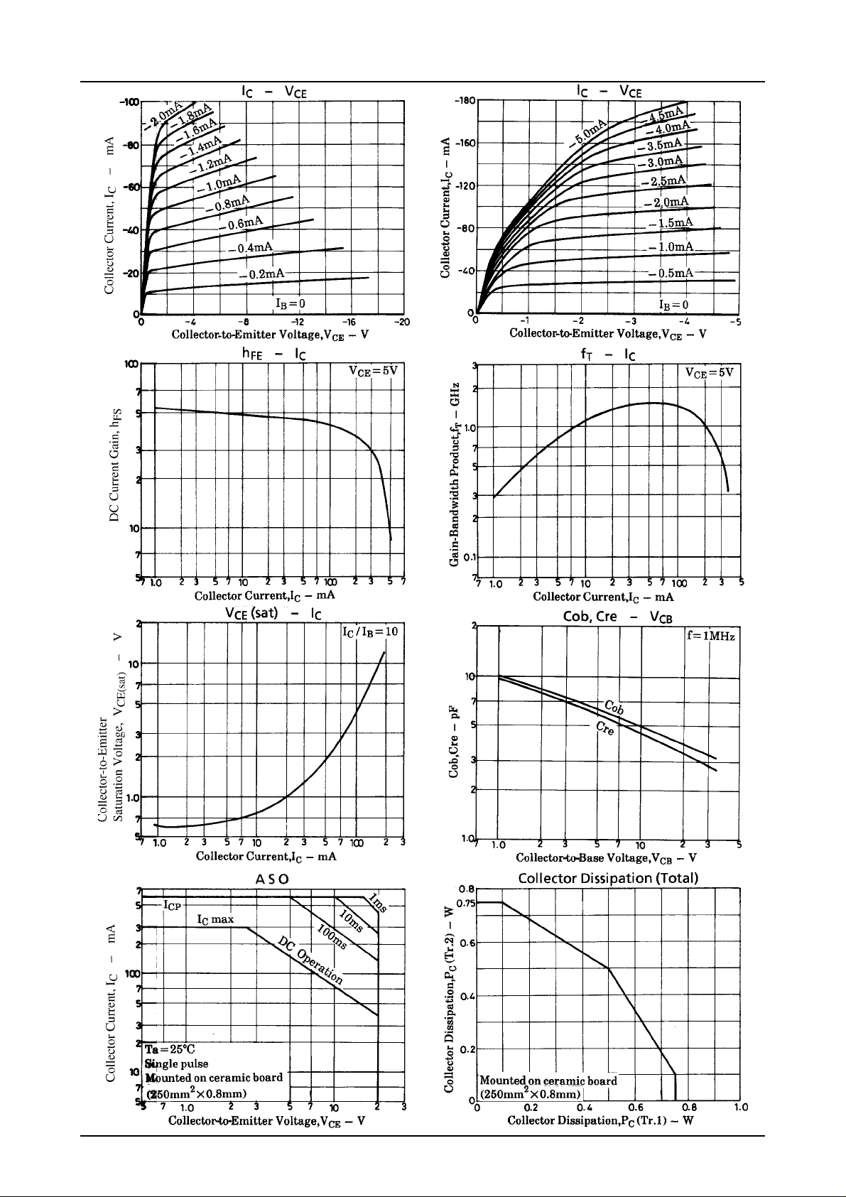
Electrical Characteristics at Ta=25˚C
retemaraPlobmySsnotidnoC
tnerruCffotuCrotcelloCI
tnerruCffotuCrettimEI
niaGtnerruCCD
oitaRniaGtnerruCCDh
ecnereffiDegatloVrettimE-ot-esaBV
tcudorPhtdiwdnaB-niaGf
ecnaticapaCtuptuOboCV
ecnaticapaCrefsnarTesreveRerCV
egatloVnoitarutaSE-CV
egatloVnoitarutaSE-BV
hEF1VECI,V5–=
hEF2VECI,V5–=
EF
T
V
OBC
V
OBE
1
V
)egral-llams(
V
EB
)llams-egral(
V
I
)tas(EC
C
I
)tas(EB
C
I,V02–=
BC
BE
EC
EC
EC
BC
BC
0=1.0–Aµ
E
I,V2–=
0=0.1–Aµ
C
Am05–=51001
C
C
I,V5–=
C
I,V5–=
C
I,V5–=
C
I,Am001–=
I,Am001–=
Am0003–=5
Am05–=6.039.0
Am001–=0.352
Am05–=
zHM1=f,V01–=
zHM1=f,V01–=
Am01–=
B
Am01–=9.0–2.1–V
B
nimpytxam
Note:The specifications shown above are for individual transistor.
However, the DC Current Gain Ratio and Base-to-Emitter Voltage Difference are for the paired transistors.
Marking:215
52098HA (KT)/41594HO (KOTO) BX-0352 No.4698-1/3
sgnitaR
5.1zHG
9.4Fp
4.4Fp
4.0–0.1–V
tinU
Vm
FP215
No.4698-2/3
 Loading...