

SANYO FH104 Datasheet
Any and all SANYO products described or contained herein do not have specifications that can handle
applications that require extremely high levels of reliability, such as life-support systems, aircraft’s
control systems, or other applications whose failure can be reasonably expected to result in serious
physical and/or material damage. Consult with your SANYO representative nearest you before using
any SANYO products described or contained herein in such applications.
SANYO assumes no responsibility for equipment failures that result from using products at values that
exceed, even momentarily, rated values (such as maximum ratings, operating condition ranges,or other
parameters) listed in products specifications of any and all SANYO products described or contained
herein.
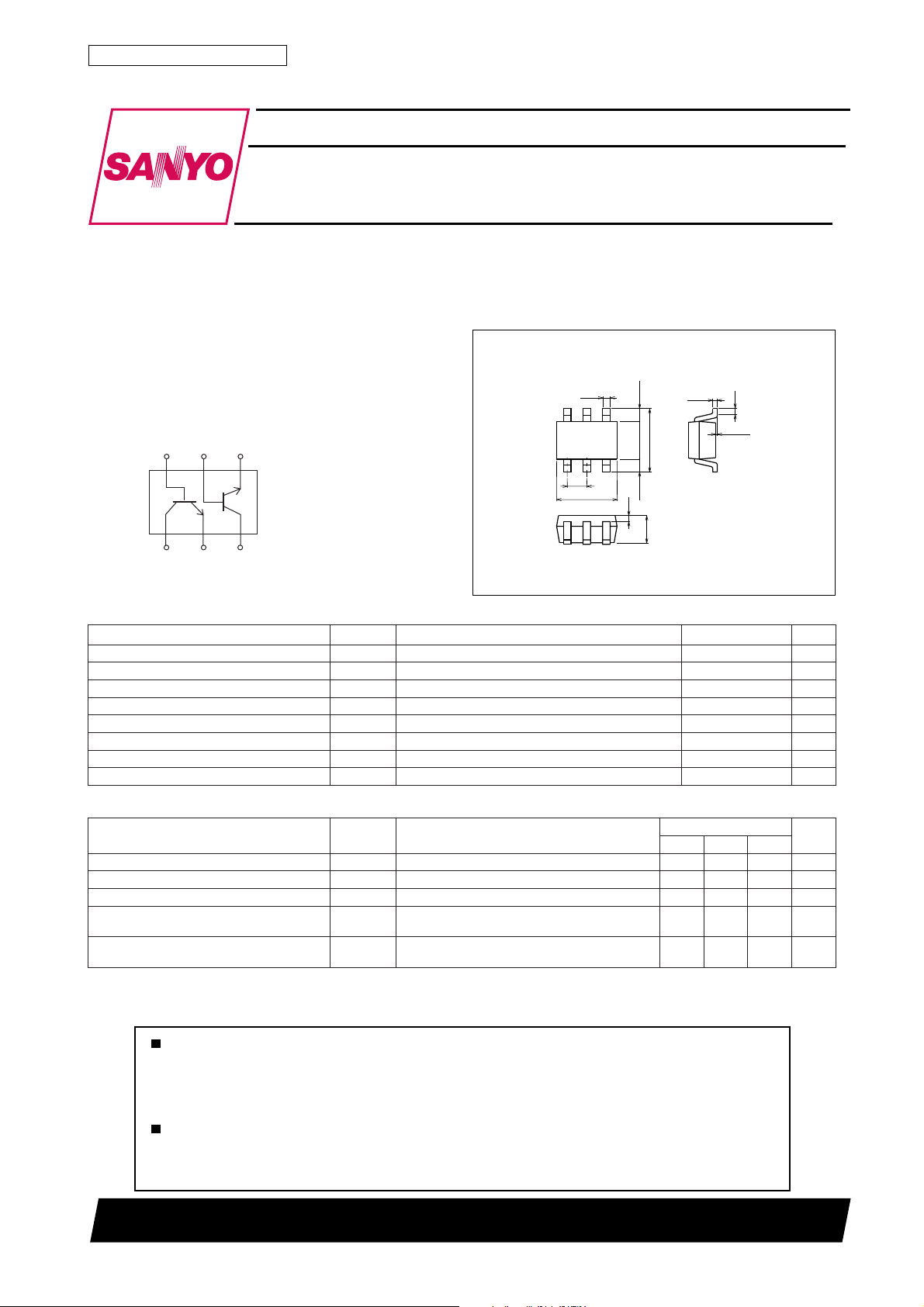
NPN Epitaxial Planar Silicon Composite Transistor
High-Frequency Low-Noise Amplifier,
Differential Amplifier Applications
Ordering number:ENN6218
FH104
SANYO Electric Co.,Ltd. Semiconductor Company
TOKYO OFFICE Tokyo Bldg., 1-10, 1 Chome, Ueno, Taito-ku, TOKYO, 110-8534 JAPAN
Features
· Composite type with 2 transistors contained in the
MCP package currently in use, improving the
mounting efficiency greatly.
· The FH104 is formed with two chips equivalent to
the 2SC4853 placed in one package.
· Excellent in thermal equilibrium and pair capability.
Electrical Connection
B2B1
E2
TR1 TR2
C1 E1 C2
Specifications
Absolute Maximum Ratings at Ta = 25˚C
retemaraPlobmySsnoitidnoCsgnitaRtinU
egatloVesaB-ot-rotcelloCV
egatloVrettimE-ot-rotcelloCV
egatloVesaB-ot-rettimEV
tnerruCrotcelloCI
noitapissiDrotcelloCP
noitapissiDlatoTP
erutarepmeTnoitcnuJjT 051
erutarepmeTegarotSgtsT 051+ot55–
OBC
OEC
OBE
C
1 unit
C
T
Package Dimensions
unit:mm
2149
[FH104]
0.25
6
12
0.65
2.0
54
3
0.2
0.4250.425
1.25
0.9
2.1
0.15
0 to 0.1
0.2
1 : Collector1
2 : Emitter1
3 : Collector2
4 : Emitter2
5 : Base2
6 : Base1
SANYO : MCP6
21V
6V
5.1V
51Am
08Wm
051Wm
˚C
˚C
Electrical Characteristics at Ta = 25˚C
retemaraPlobmySsnoitidnoC
tnerruCffotuCrotcelloCI
tnerruCffotuCrettimEI
niaGtnerruCCD
oitaRniaGtnerruCCD
ecnereffiDegatloVrettimE-ot-esaB
h
h
V
V
OBC
V
OBE
V
EF
EF
V
)egral/llams(
EB
V
)llams-egral(
I,V01=
BC
BE
EC
EC
BC
0=0.1Aµ
E
I,V1=
0=01Aµ
C
I,V1=
Am1=
C
I,V1=
Am1=7.059.0
C
I,V1=
Am1=0.1Vm
C
nimpytxam
Note) The specifications shown above are for each individual transistor. However, the ratings for hFE (small/large) and VBE (large-small) indicate pair
characteristics.
Marking : 104
D1099TS (KOTO) TA-2353 No.6218–1/4
sgnitaR
09002
Continued on next page.
tinU
Continued from preceding page.
retemaraPlobmySsnoitidnoC
tcudorPhtdiwdnaB-niaGf
ecnaticapaCtuptuO
niaGrefsnarTdrawroF
erugiFesioN
3
2
100
FE
7
5
3
2
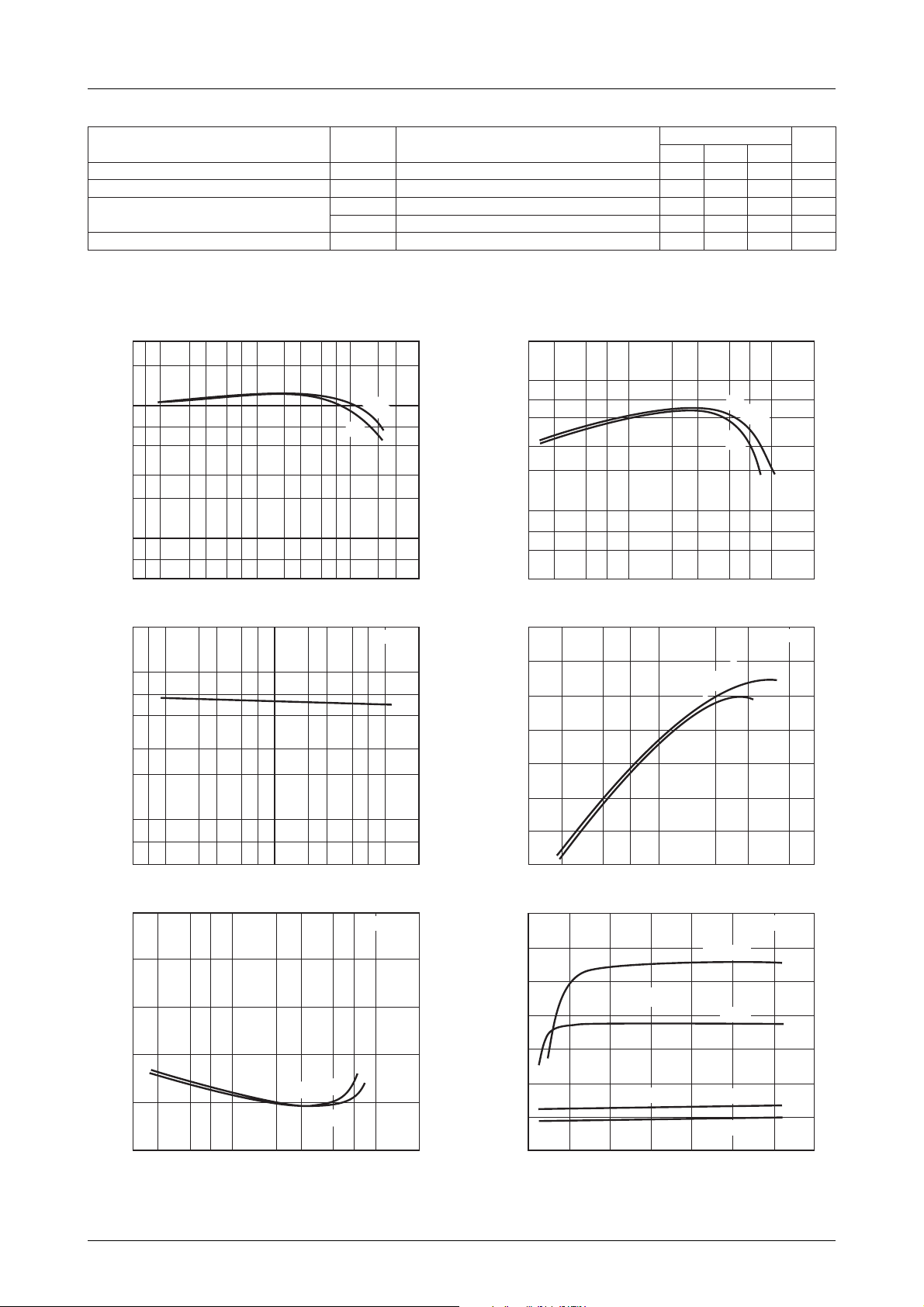
DC Current Gain, h
10
7
5
5
2
1.0
7
5
3
2
0.1
Output Capacitance, Cob – pF
7
5
57
10
8
6
4
23 23571023 5775
0.1 1.0
Collector Current, IC–mA
Cob -- V
23 57
0.1
Collector-to-Base Voltage, VCB-- V
h
FE
1.0
NF -- I
-- I
C
V
1V
CB
23 57102
C
V
T
V
boC
2
V
1
|e12S|
2
V
2
|e12S|
FNVECI,V1=
CE
=2V
IT00311
f=1MHz
IT00313
f=1GHz
FH104
EC
BC
EC
EC
sgnitaR
nimpytxam
I,V1=
Am1=
C
zHM1=f,V1=
I,V1=
C
I,V2=
C
C
zHG1=f,Am1=
zHG1=f,Am3=
zHG1=f,Am1=6.25.4Bd
f
-- I
T
C
– GHz
T
2
10
7
5
5zHG
6.00.1Fp
5.47 Bd
5.01Bd
V
CE
=2V
tinU
1V
3
2
1.0
7
5
Gain-Bandwidth Product, f
3
23 57 2 2357
14
12
–dBS21e
2
10
1.0 10
Collector Current, IC–mA
S21e
2
-- I
C
=2V
CE
V
IT00312
f=1GHz
1V
8
6
4
2
Forward Transfer Gain, S21e
0
23 57
14
12
10
8
–dB
2
6
Collector Current, IC–mA
1.0
S21e2, NF -- V
S21e
23 57
IT00314
CE
f=1GHz
IC=3mA
2
1mA
Noise Figure, NF – dB
2
0
23 2 2357
=1V
V
CE
2V
1.0 10
Collector Current, IC–mA
5
4
2
7
IT00315
0
Collector-to-Emitter Voltage,VCE–V
NF
IC=1mA
3mA
76543210
IT00316
No.6218–2/4
 Loading...