Sanyo EM-sl30 Schematic

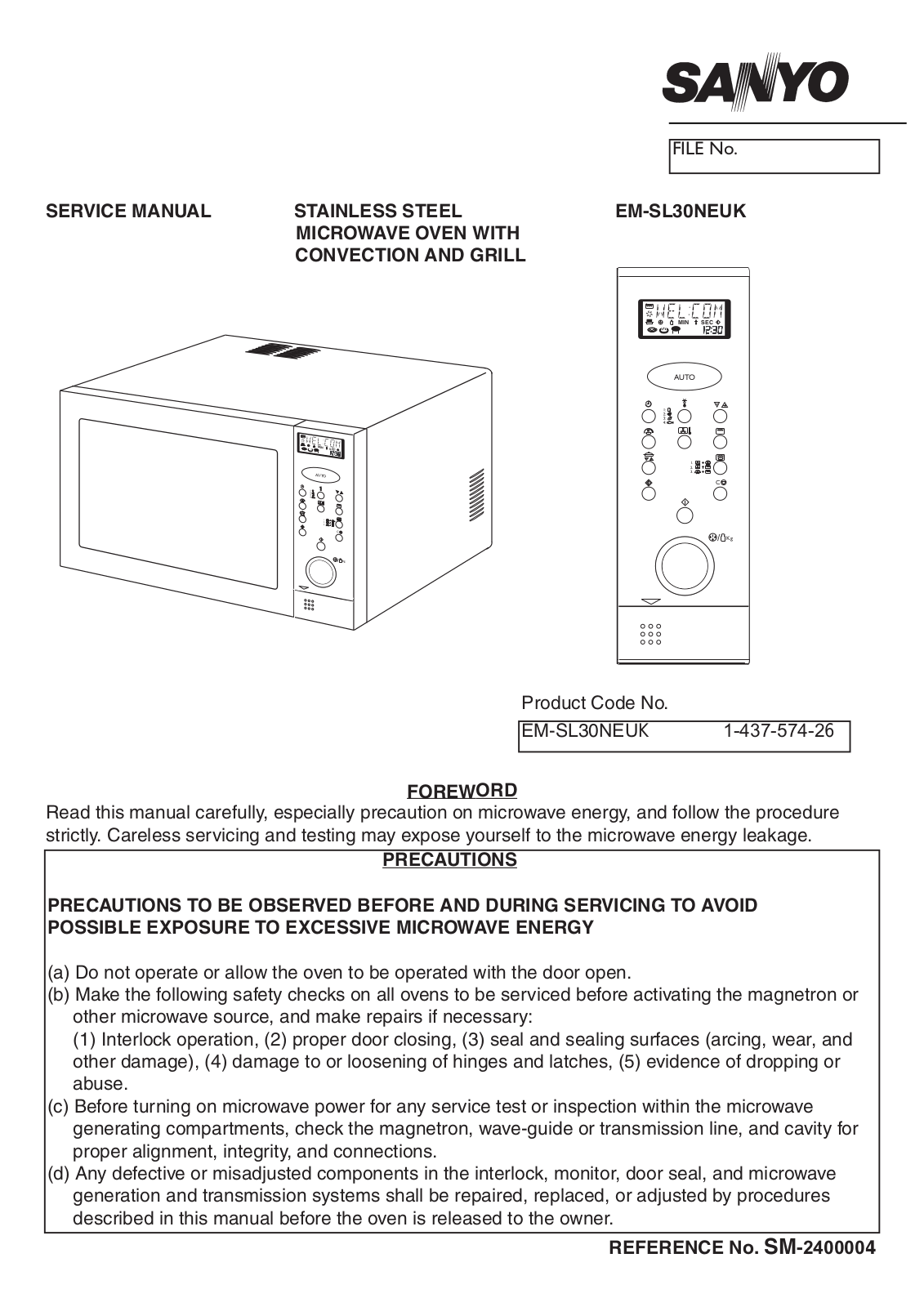
SERVICE MANUAL

STAINLESS STEEL


MICROWAVE OVEN WITH


CONVECTION AND GRILL

MIN

SEC


AUTO


1.


2.


3.


C


/

Kg

FILE No.

EM-SL30NEUKUK

MIN SEC

AUTO

1.

2.

3.

C

/ Kg

Product Code No.

EM-SL30NEUK 1-437-574-26

FOREWORD

Read this manual carefully, especially precaution on microwave energy, and follow the procedure strictly. Careless servicing and testing may expose yourself to the microwave energy leakage.

PRECAUTIONS

PRECAUTIONS TO BE OBSERVED BEFORE AND DURING SERVICING TO AVOID POSSIBLE EXPOSURE TO EXCESSIVE MICROWAVE ENERGY

(a)Do not operate or allow the oven to be operated with the door open.

(b)Make the following safety checks on all ovens to be serviced before activating the magnetron or other microwave source, and make repairs if necessary:

(1) Interlock operation, (2) proper door closing, (3) seal and sealing surfaces (arcing, wear, and other damage), (4) damage to or loosening of hinges and latches, (5) evidence of dropping or abuse.

(c)Before turning on microwave power for any service test or inspection within the microwave generating compartments, check the magnetron, wave-guide or transmission line, and cavity for proper alignment, integrity, and connections.

(d)Any defective or misadjusted components in the interlock, monitor, door seal, and microwave generation and transmission systems shall be repaired, replaced, or adjusted by procedures described in this manual before the oven is released to the owner.

REFERENCE No. SM-2400004


TABLE OF CONTENTS


Adjustment Procedures........................................

1

Circuit Diagram....................................................

4

Specifications.......................................................

2

Test Procedures and Troubleshooting.................

5-15

Power Output Measurement................................

2

Disassembly Instructions.....................................

16-17

Precautions and Repair Service Tips...................

2

Exploded View and Parts list................................

18-23

Oven Control Panel..............................................

3

Control Circuit Board............................................

24


Overall Circuit Diagrams......................................

25


CAUTION

MICROWAVE ENERGY

PERSONNEL SHOULD NOT BE EXPOSED TO

THE MICROWAVE ENERGY WHICH MAY RADI-

ATE FROM THE MAGNETRON OR OTHER

MICROWAVE GENERATING DEVICE IF IT IS

IMPROPERLY USED OR CONNECTED. ALL

INPUT AND OUTPUT MICROWAVE CONNEC-

TIONS, WAVE GUIDES, FLANGES, AND GAS-

KETS MUST BE SECURE. NEVER OPERATE

THE DEVICE WITHOUT A MICROWAVE ENER-

GY ABSORBING LOAD ATTACHED. NEVER

LOOK INTO AN OPEN WAVE GUIDE OR

ANTENNA WHILE THE DEVICE IS ENERGISED.


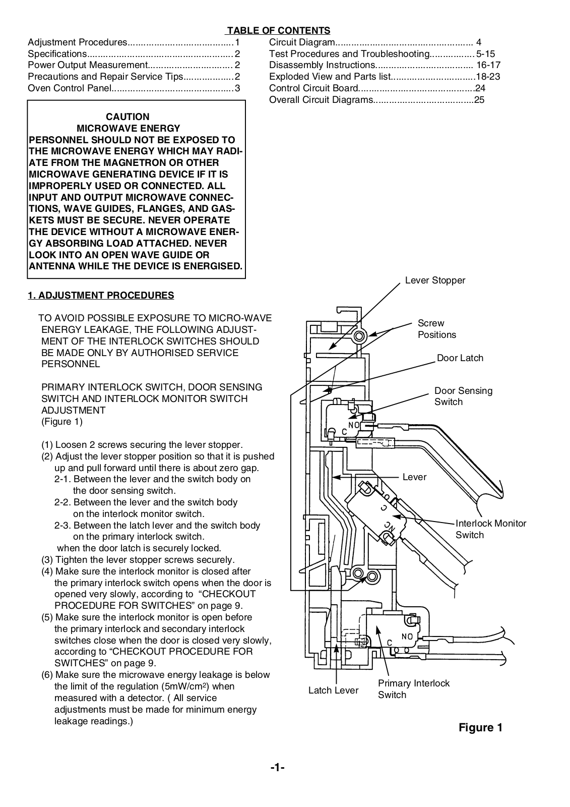
Lever Stopper


1. ADJUSTMENT PROCEDURES


TO AVOID POSSIBLE EXPOSURE TO MICRO-WAVE


Screw


ENERGY LEAKAGE, THE FOLLOWING ADJUST-


Positions


MENT OF THE INTERLOCK SWITCHES SHOULD


BE MADE ONLY BY AUTHORISED SERVICE


Door Latch


PERSONNEL


PRIMARY INTERLOCK SWITCH, DOOR SENSING


Door Sensing

SWITCH AND INTERLOCK MONITOR SWITCH


Switch

ADJUSTMENT


(Figure 1)

(1)Loosen 2 screws securing the lever stopper.

(2)Adjust the lever stopper position so that it is pushed

up and pull forward until there is about zero gap.


2-1. Between the lever and the switch body on


Lever


the door sensing switch.


2-2. Between the lever and the switch body


on the interlock monitor switch.


2-3. Between the latch lever and the switch body


Interlock Monitor

on the primary interlock switch.


Switch

when the door latch is securely locked.


(3) Tighten the lever stopper screws securely.


(4) Make sure the interlock monitor is closed after


the primary interlock switch opens when the door is


opened very slowly, according to “CHECKOUT


PROCEDURE FOR SWITCHES” on page 9.


(5) Make sure the interlock monitor is open before


the primary interlock and secondary interlock


switches close when the door is closed very slowly,


according to “CHECKOUT PROCEDURE FOR


SWITCHES” on page 9.


(6) Make sure the microwave energy leakage is below


the limit of the regulation (5mW/cm2) when


Primary Interlock


Latch Lever


measured with a detector. ( All service


Switch


adjustments must be made for minimum energy


leakage readings.)


Figure 1


-1-

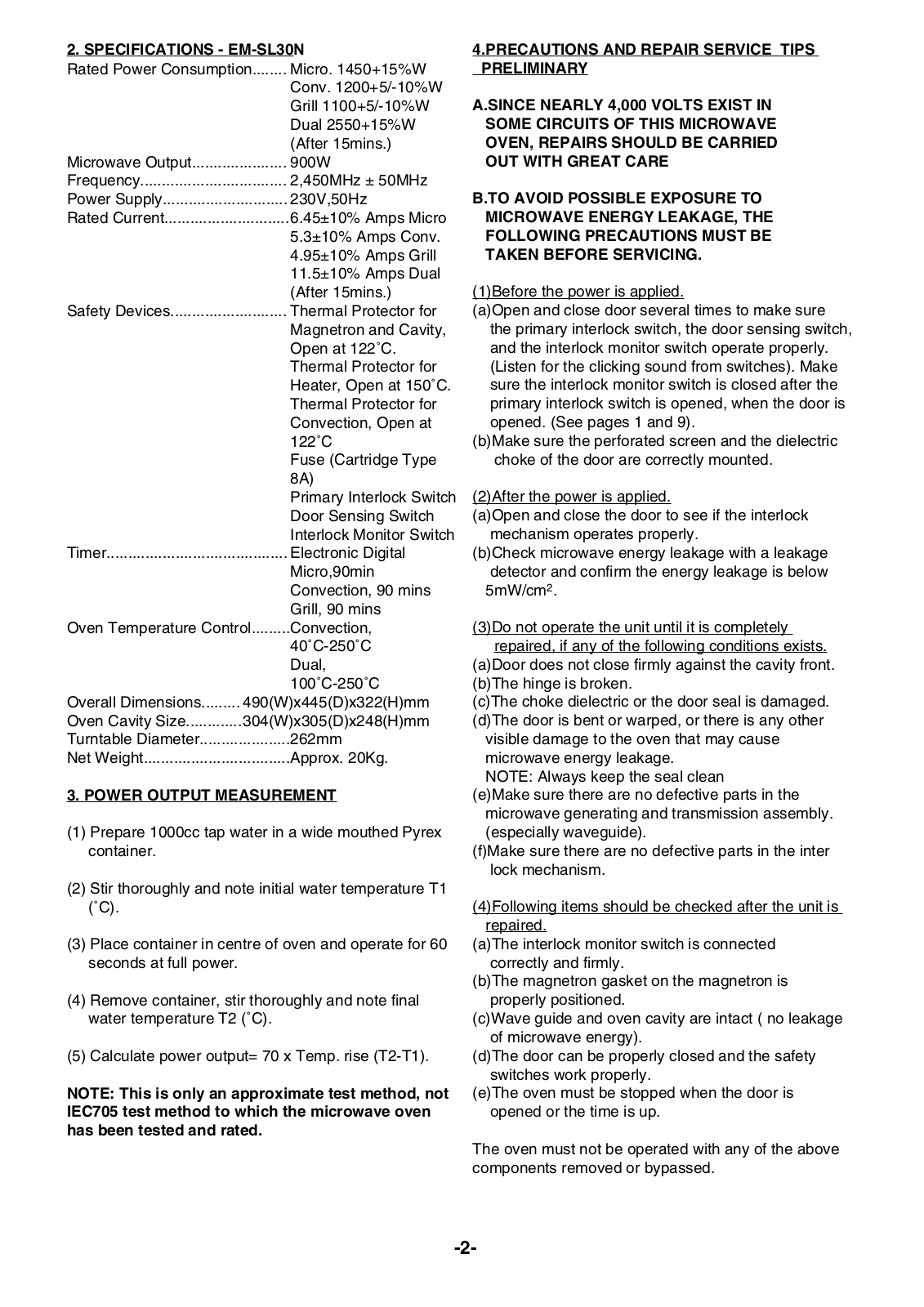
2. SPECIFICATIONS - EM-SL30N

Rated Power Consumption........

Micro. 1450+15%W


Conv. 1200+5/-10%W


Grill 1100+5/-10%W


Dual 2550+15%W


(After 15mins.)

Microwave Output......................


900W

Frequency..................................


2,450MHz ± 50MHz

Power Supply.............................


230V,50Hz

Rated Current.............................


6.45±10% Amps Micro


5.3±10% Amps Conv.


4.95±10% Amps Grill


11.5±10% Amps Dual


(After 15mins.)

Safety Devices...........................


Thermal Protector for


Magnetron and Cavity,


Open at 122˚C.


Thermal Protector for


Heater, Open at 150˚C.


Thermal Protector for


Convection, Open at


122˚C


Fuse (Cartridge Type


8A)


Primary Interlock Switch


Door Sensing Switch


Interlock Monitor Switch

Timer..........................................


Electronic Digital


Micro,90min


Convection, 90 mins


Grill, 90 mins

Oven Temperature Control.........

Convection,


40˚C-250˚C


Dual,


100˚C-250˚C

Overall Dimensions.........

490(W)x445(D)x322(H)mm

Oven Cavity Size.............

304(W)x305(D)x248(H)mm

Turntable Diameter.....................


262mm

Net Weight..................................


Approx. 20Kg.

3. POWER OUTPUT MEASUREMENT

(1)Prepare 1000cc tap water in a wide mouthed Pyrex container.

(2)Stir thoroughly and note initial water temperature T1 (˚C).

(3)Place container in centre of oven and operate for 60 seconds at full power.

(4)Remove container, stir thoroughly and note final water temperature T2 (˚C).

(5)Calculate power output= 70 x Temp. rise (T2-T1).

NOTE: This is only an approximate test method, not IEC705 test method to which the microwave oven has been tested and rated.

4.PRECAUTIONS AND REPAIR SERVICE TIPS PRELIMINARY

A.SINCE NEARLY 4,000 VOLTS EXIST IN SOME CIRCUITS OF THIS MICROWAVE OVEN, REPAIRS SHOULD BE CARRIED OUT WITH GREAT CARE

B.TO AVOID POSSIBLE EXPOSURE TO MICROWAVE ENERGY LEAKAGE, THE FOLLOWING PRECAUTIONS MUST BE TAKEN BEFORE SERVICING.

(1)Before the power is applied.

(a)Open and close door several times to make sure the primary interlock switch, the door sensing switch, and the interlock monitor switch operate properly. (Listen for the clicking sound from switches). Make sure the interlock monitor switch is closed after the primary interlock switch is opened, when the door is opened. (See pages 1 and 9).

(b)Make sure the perforated screen and the dielectric choke of the door are correctly mounted.

(2)After the power is applied.

(a)Open and close the door to see if the interlock mechanism operates properly.

(b)Check microwave energy leakage with a leakage detector and confirm the energy leakage is below 5mW/cm2.

(3)Do not operate the unit until it is completely repaired, if any of the following conditions exists.

(a)Door does not close firmly against the cavity front. (b)The hinge is broken.

(c)The choke dielectric or the door seal is damaged. (d)The door is bent or warped, or there is any other

visible damage to the oven that may cause microwave energy leakage.

NOTE: Always keep the seal clean

(e)Make sure there are no defective parts in the microwave generating and transmission assembly. (especially waveguide).

(f)Make sure there are no defective parts in the inter lock mechanism.

(4)Following items should be checked after the unit is repaired.

(a)The interlock monitor switch is connected correctly and firmly.

(b)The magnetron gasket on the magnetron is properly positioned.

(c)Wave guide and oven cavity are intact ( no leakage of microwave energy).

(d)The door can be properly closed and the safety switches work properly.

(e)The oven must be stopped when the door is opened or the time is up.

The oven must not be operated with any of the above components removed or bypassed.

-2-

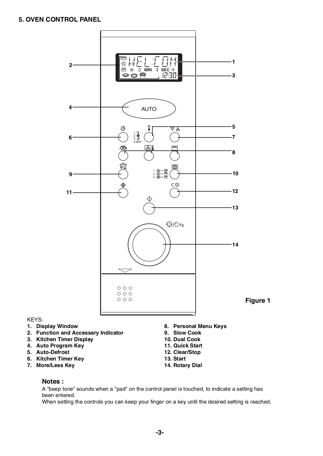
5. OVEN CONTROL PANEL


2


1


MIN

SEC


3


4

AUTO


5


6


7


8


9

1.


10


2.


3.


C


11


12


13


/ Kg


14


Figure 1

KEYS:


1.

Display Window


8.

Personal Menu Keys

2.

Function and Accessary Indicator


9.

Slow Cook

3.

Kitchen Timer Display


10. Dual Cook

4.

Auto Program Key


11. Quick Start

5.

Auto-Defrost


12. Clear/Stop

6.

Kitchen Timer Key


13. Start

7.

More/Less Key


14. Rotary Dial

Notes :

A "beep tone" sounds when a "pad" on the control panel is touched, to indicate a setting has been entered.

When setting the controls you can keep your finger on a key until the desired setting is reached.

-3-

Sanyo EM-sl30 Schematic

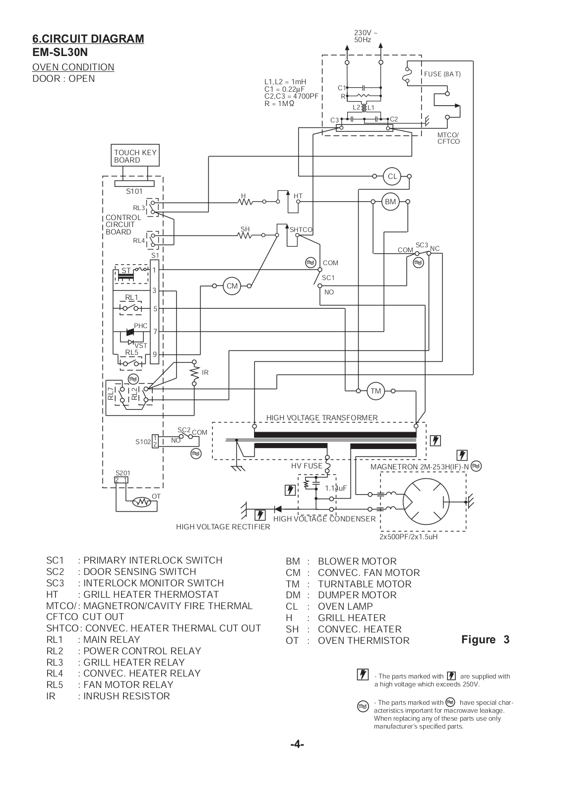
6.CIRCUIT DIAGRAM EM-SL30N

OVEN CONDITION

DOOR : OPEN

TOUCH KEY

BOARD

S101

RL3

CONTROL

CIRCUIT

BOARD


RL4


S1


ST

1


RL1

3


5


PHC

7


VST


RL5

9

RL7

RL2


S102

1


2

S201


2

1


OT


230V ~


50Hz


L1,L2 = 1mH


FUSE (8A T)


C1


C1 = 0.22 F


C2,C3 = 4700PF

R


R = 1M

L2

L1


C3

C2


MTCO/


CFTCO


CL

H

HT


BM


SH SHTCO

COM SC3 NC

COM

SC1

CM

NO

IR

TM

HIGH VOLTAGE TRANSFORMER

SC2 COM

NO

HV FUSE

MAGNETRON 2M-253H(IF)-N

1.14uF

HIGH VOLTAGE CONDENSER HIGH VOLTAGE RECTIFIER

2x500PF/2x1.5uH

SC1

: PRIMARY INTERLOCK SWITCH

SC2

: DOOR SENSING SWITCH

SC3

: INTERLOCK MONITOR SWITCH

HT

: GRILL HEATER THERMOSTAT

MTCO/ : MAGNETRON/CAVITY FIRE THERMAL

CFTCO CUT OUT

SHTCO: CONVEC. HEATER THERMAL CUT OUT

RL1

: MAIN RELAY

RL2

: POWER CONTROL RELAY

RL3

: GRILL HEATER RELAY

RL4

: CONVEC. HEATER RELAY

RL5

: FAN MOTOR RELAY

IR

: INRUSH RESISTOR

BM :

BLOWER MOTOR


CM

:

CONVEC. FAN MOTOR


TM

:

TURNTABLE MOTOR


DM

:

DUMPER MOTOR


CL

:

OVEN LAMP


H

:

GRILL HEATER


SH

:

CONVEC. HEATER


OT

:

OVEN THERMISTOR

Figure 3

- The parts marked with

are supplied with

a high voltage which exceeds 250V.

- The parts marked with

have special char-

acteristics important for macrowave leakage. When replacing any of these parts use only manufacturer's specified parts.

-4-

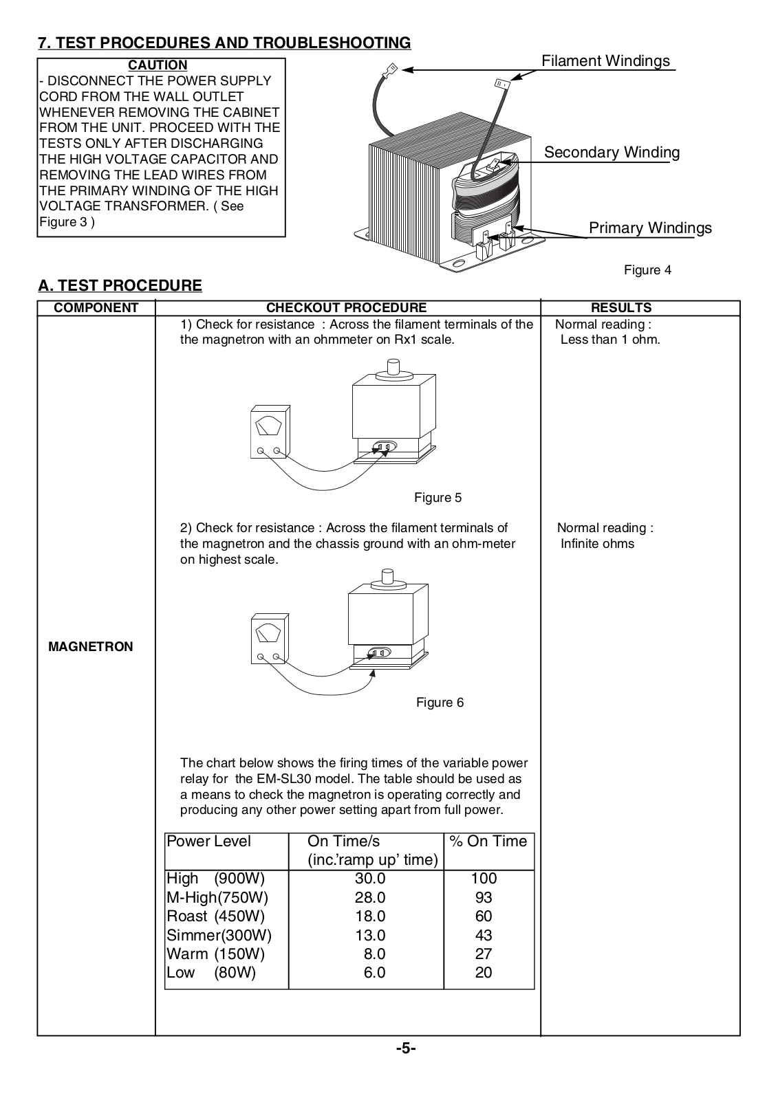
7. TEST PROCEDURES AND TROUBLESHOOTING

CAUTION

- DISCONNECT THE POWER SUPPLY CORD FROM THE WALL OUTLET WHENEVER REMOVING THE CABINET FROM THE UNIT. PROCEED WITH THE TESTS ONLY AFTER DISCHARGING THE HIGH VOLTAGE CAPACITOR AND REMOVING THE LEAD WIRES FROM THE PRIMARY WINDING OF THE HIGH VOLTAGE TRANSFORMER. ( See Figure 3 )

A. TEST PROCEDURE

Filament Windings

Secondary Winding

Primary Windings

Figure 4

COMPONENT


CHECKOUT PROCEDURE

RESULTS


1) Check for resistance : Across the filament terminals of the

Normal reading :


the magnetron with an ohmmeter on Rx1 scale.

Less than 1 ohm.


Figure 5


2) Check for resistance : Across the filament terminals of

Normal reading :

the magnetron and the chassis ground with an ohm-meter

Infinite ohms

on highest scale.


MAGNETRON

Figure 6

The chart below shows the firing times of the variable power relay for the EM-SL30 model. The table should be used as a means to check the magnetron is operating correctly and producing any other power setting apart from full power.

Power Level

On Time/s

% On Time


(inc.’ramp up’ time)


High

(900W)

30.0

100

M-High(750W)

28.0

93

Roast (450W)

18.0

60

Simmer(300W)

13.0

43

Warm (150W)

8.0

27

Low

(80W)

6.0

20


-5-

COMPONENT

CHECKOUT PROCEDURE

RESULTS


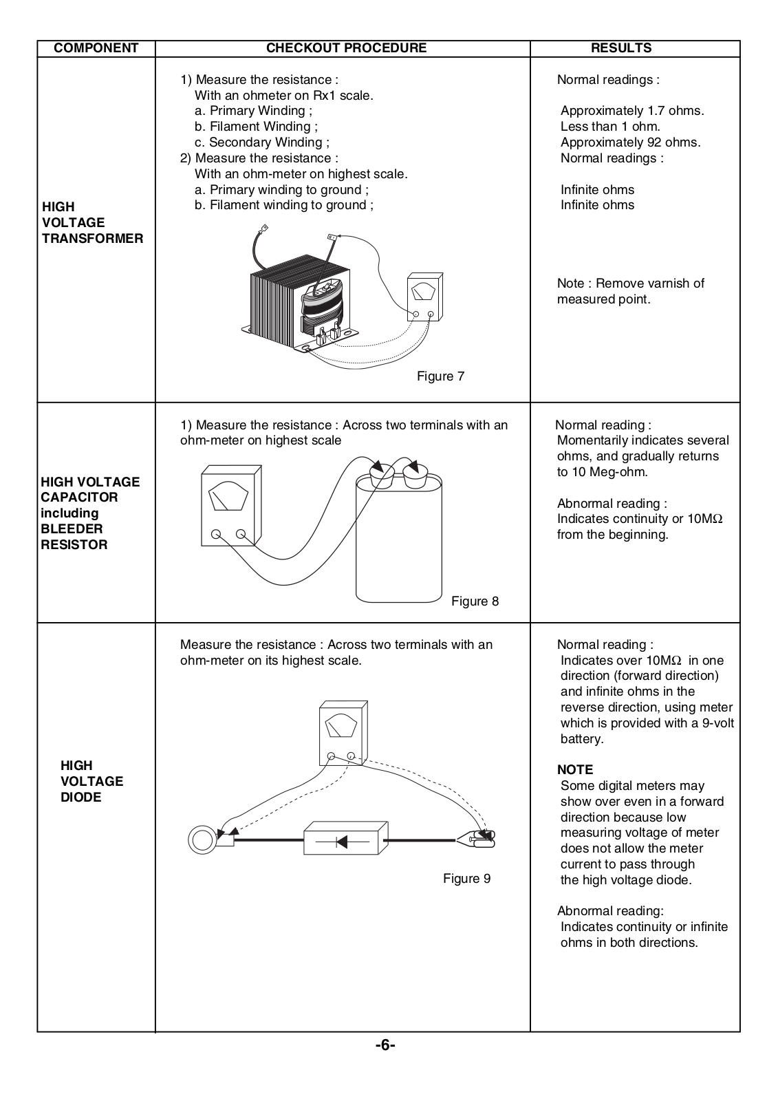
1) Measure the resistance :

Normal readings :


With an ohmeter on Rx1 scale.


a. Primary Winding ;

Approximately 1.7 ohms.


b. Filament Winding ;

Less than 1 ohm.


c. Secondary Winding ;

Approximately 92 ohms.


2) Measure the resistance :

Normal readings :


With an ohm-meter on highest scale.


a. Primary winding to ground ;

Infinite ohms

HIGH

b. Filament winding to ground ;

Infinite ohms

VOLTAGE


TRANSFORMER


Note : Remove varnish of


measured point.


Figure 7


1) Measure the resistance : Across two terminals with an

Normal reading :


ohm-meter on highest scale

Momentarily indicates several


ohms, and gradually returns


to 10 Meg-ohm.


HIGH VOLTAGE


CAPACITOR


Abnormal reading :


including


Indicates continuity or 10MΩ


BLEEDER


from the beginning.


RESISTOR


Figure

8


Measure the resistance : Across two terminals with an

Normal reading :


ohm-meter on its highest scale.

Indicates over 10MΩ in one


direction (forward direction)


and infinite ohms in the


reverse direction, using meter


which is provided with a 9-volt


battery.


HIGH


NOTE


VOLTAGE


Some digital meters may


DIODE


show over even in a forward


direction because low


measuring voltage of meter


does not allow the meter


current to pass through


Figure 9


the high voltage diode.


Abnormal reading:


Indicates continuity or infinite


ohms in both directions.

-6-


COMPONENT


CHECKOUT PROCEDURE


RESULT


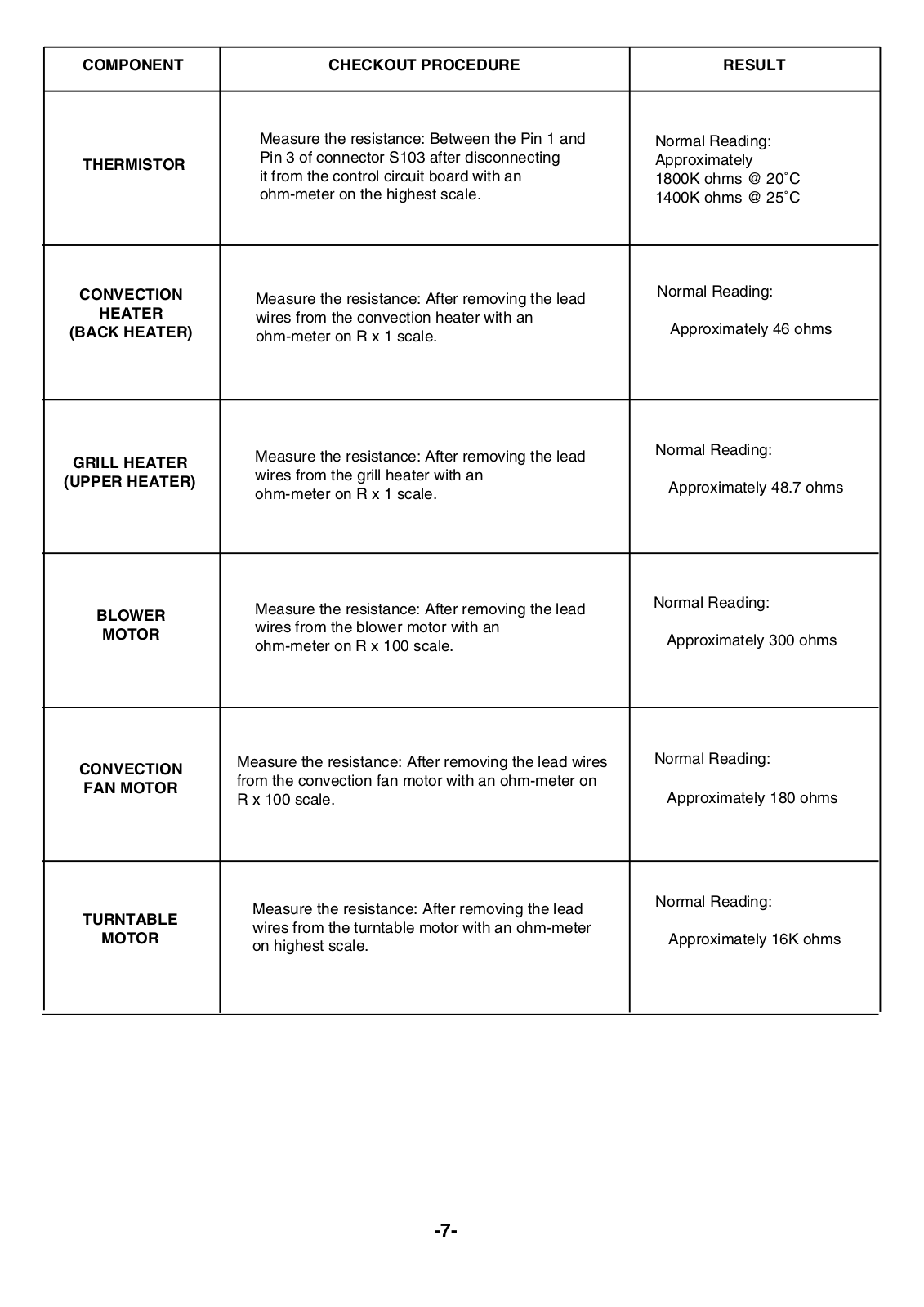
Measure the resistance: Between the Pin 1 and


Normal Reading:


THERMISTOR


Pin 3 of connector S103 after disconnecting


Approximately


it from the control circuit board with an


1800K ohms @ 20˚C


ohm-meter on the highest scale.


1400K ohms @ 25˚C


Normal Reading:


CONVECTION


Measure the resistance: After removing the lead


HEATER


wires from the convection heater with an


Approximately 46 ohms


(BACK HEATER)


ohm-meter on R x 1 scale.


Normal Reading:


Measure the resistance: After removing the lead


GRILL HEATER


wires from the grill heater with an


(UPPER HEATER)


Approximately 48.7 ohms


ohm-meter on R x 1 scale.


Normal Reading:


Measure the resistance: After removing the lead


BLOWER


wires from the blower motor with an


MOTOR


Approximately 300 ohms


ohm-meter on R x 100 scale.


Normal Reading:


Measure the resistance: After removing the lead wires


CONVECTION


from the convection fan motor with an ohm-meter on


FAN MOTOR


Approximately 180 ohms


R x 100 scale.


Normal Reading:


Measure the resistance: After removing the lead


TURNTABLE


wires from the turntable motor with an ohm-meter


MOTOR


Approximately 16K ohms


on highest scale.


-7-

COMPONENT

CHECKOUT PROCEDURE

RESULTS

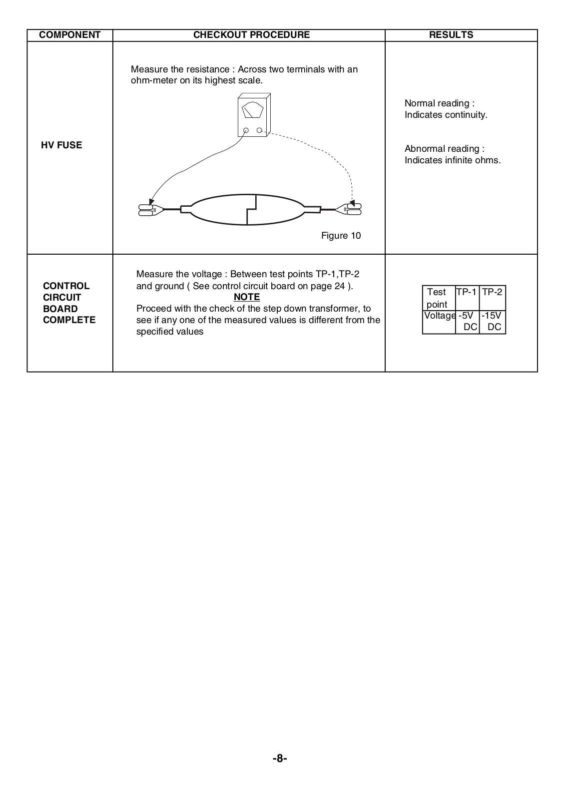
Measure the resistance : Across two terminals with an ohm-meter on its highest scale.

Normal reading :

Indicates continuity.

HV FUSE

Abnormal reading :


Indicates infinite ohms.


Figure 10


Measure the voltage : Between test points TP-1,TP-2


and ground ( See control circuit board on page 24 ).


CONTROL


Test

TP-1

TP-2


CIRCUIT

NOTE


point


BOARD

Proceed with the check of the step down transformer, to


Voltage

-5V

-15V


COMPLETE

see if any one of the measured values is different from the


DC

DC


specified values


-8-

Loading...
+ 18 hidden pages