

SANYO DVD-SL38 Service Manual 00-16
DVD MECHANISM REPLACEMENT
1. Cautionary instructions in handling the assy
(Safety instructions)
Optical pickup
The laser beam used in the pickup is classified as "class 2".
Exposing your eyes or skin to the beam is harmful. Take care
not to do so.
(Caution against static electricity and leakage voltage)
Ground securely the work tables, tools, fixtures, soldering irons
(including those made of ceramic) and measuring instruments
used in the production lines and inspection departments that
handle loaders. The workers shall also be grounded.
(Cautionary instructions in handling)
Do not touch the object lens when handling a loader, or the lens
will be stained, resulting in inadequate playability.
There is no power supply protection circuit provided for this
product or adjustment/inspection device. Short-circuiting may lead
to fire or damage.
Take care so as to protect from exposure to water, the entry of
metallic pieces or dew condensation.
In particular, a strong magnet adjacent to the pickup will not only
get inoperative but can damage the pickup if a small metallic
piece, such as a screw or swarm, enters.
The loader edge can cause injury if inadvertently handled.
Do not touch a rotating disk, or injury may result.
This product is a precision device. Handle carefully.
A shock or dropping will cause misalignment or destruction. If it
should occur, refer to clause 2.
This product is so designed as to endure an initial shock
equivalent to a drop from a height of approx. 90 cm under the
packed condition.
After the initial shock, the resistivity will still remain at a level of
50 to 60 G, but the mechanical robustness will weaken.
Do not place in a dusty location.
The entry and deposition of dirt into or on the pickup lens or
moving section will cause malfunction or degradation.
(Connectors)
Do not connect or disconnect while power is on.
Connecting or disconnecting signal wires or the main power cord
when the power is on may destruct the unit or fixture.
When connecting, push all the way in securely.
An insufficient insertion may cause a bad contact, leading to an
erroneous operation.
Do not connect or disconnect roughly by an excessively strong
force, or a broken wire or bad contact may result.
Semiconductors are connected. Do not touch connector terminals
directly.
If the worker is grounded, there is nothing to worry about static
electricity, but the rust on the connector terminal surface caused
by the touch may result in bad contact.
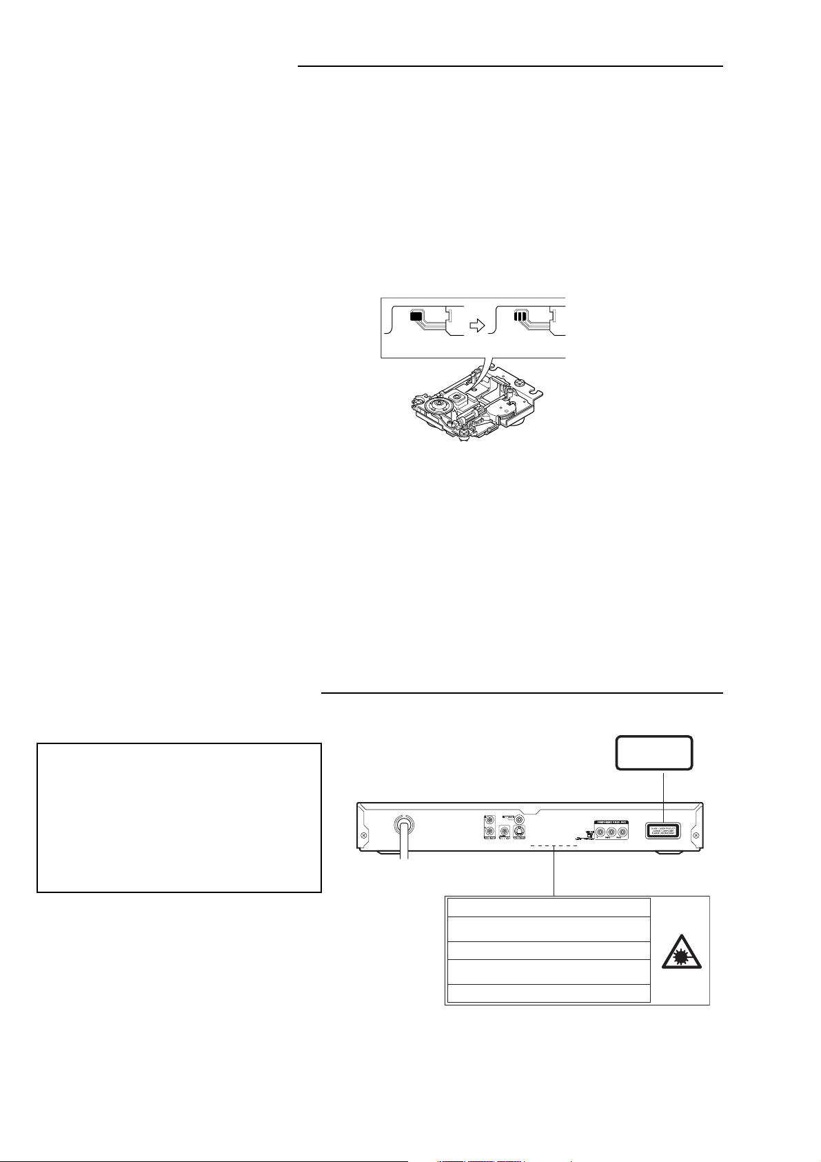
(Caution)
Before disconnecting FFC
cable, make it "SHORT" as
shown left.
After connecting FFC
(OPEN)(SHORT)
cable,make it "OPEN" as
shownleft.
(Power source)
The power source need be good in quality (free from
instantaneous interruptions or noises).
A low quality power source may well cause malfunction.
(Storage)
Do not place or store in a dusty place or a place where dew
condensation is possible.
The entry and deposition of dirt or dust into or on the pickup lens
or moving section will cause malfunction or degradation.
Also, dew condensation causes rust; the rust penetrate into the
precision part of a pickup, causing malfunction, or degrading the
optical quality of the internal lens and reflector, which also leads
to malfunction.
LASER BEAM SAFETY PRECAUTION
• Pick-up that emits a laser beam is used in this CD player section.
CAUTION :
USE OF CONTROLS OR ADJUSTMENTS
OR PERFORMANCE OF PROCEDURES
OTHER THAN THOSE SPECIFIED HEREIN
MAY RESULT IN HAZARDOUS RADIATION
EXPOSURE
LASER OUTPUT.......... 0.6 mW Max. (CW)
WAVELENGTH ............. 790 nm
CLASS 1 LASER PRODUCT
LUOKAN 1 LASERLAITE
KLASS 1 LASERAPPARAT
CAUTION – IN VISIBLE LASER RADIA TION WHEN OPEN AND
INTERLOCKS DEFEA TED. A VOID EXPOSURE TO BEAM.
ADVARSEL – US YNLIG LASER STR ÅLING VED ÅBNING, N ÅR
SIKKERHEDSAFBRYDERE ER UDE AF FUNKTION, UNDG Å UD S ÆTTELSE
FOR STR ÅLING.
VARNING – OS YNLIG LASER STR ÅLNING N ÄR DENNA DEL ÄR ÖPPNAD
OCH SP ÄRR ÄR URKOPPLAD. STR ÅLEN ÄR F ARLIG.
VORSICHT – UN SICHTBARE LASERSTRAHLUNG TRITT AUS, WENN
DECKEL GE ÖFFNET UND WENN SICHERHEITSVERRIEGELUNG
ÜBERBRÜCKT IST. NICHT, DEM STRAHL AUSSETZEN.
VARO – A VATTAESSA JA SUOJALUKITUS OHITETT AESSA OLET AL TTIINA
NÄKYMÄTTÖMÄLLE LASERS ÄTEILYLLE. ÄLÄ KA TSO S ÄTEESEEN.
- 1 -
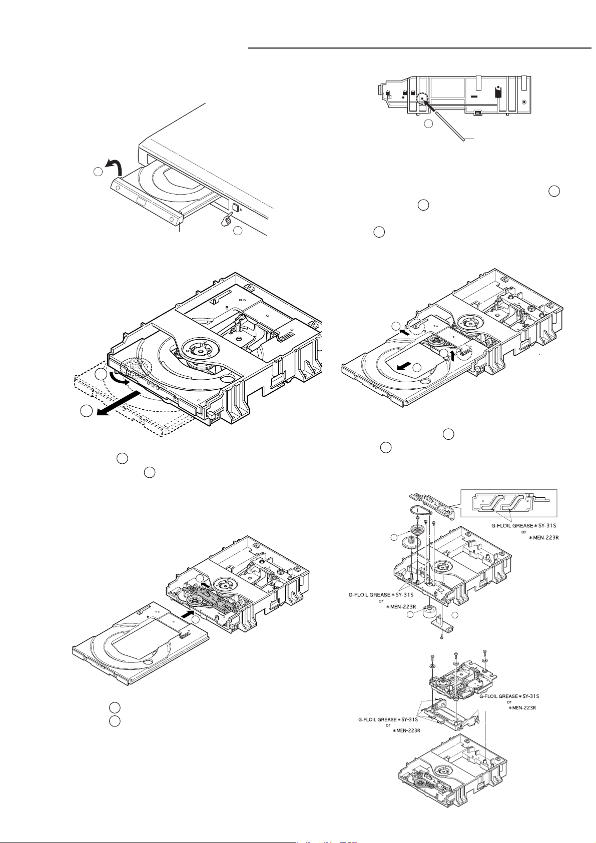
MECHANISM REPLACEMENT
: Clean the groove by alcohol well.
A
A
A
G-SANKOL
G-SANKOL
1. How to Remove DVD Mechanism
First, it is necessary to remove Escutcheon.
1
2
Escutcheon
2. How to remove the tray.
1
Side of DVD mechanism
Front
3
Cylindrical thing
Rear
How to remove Escutcheon.
1
An eject button is pushed and a tray is taken out.
Please remove Escutcheon, as shown in the left figure 2 .
When an eject button 1 does not function. Above figure
Please insert a cylindrical thing with a diameter of 3mm or less
1
in the hole 3 in the side of a DVD mechanism.
A tray is pushed out.
1
1
2
2
Rotatethe1gear.
Moveforwardthe2tray.
3. How to insert the tray.
Moveboththerightandleft1traypinstotheends.
Removethe2tray.
4. Base mechanism mounting parts.
1
2
Movethe1slidetotheleftend.
Insertthe2tray.
G-SANKOL
G-SANKOL
- 2 -
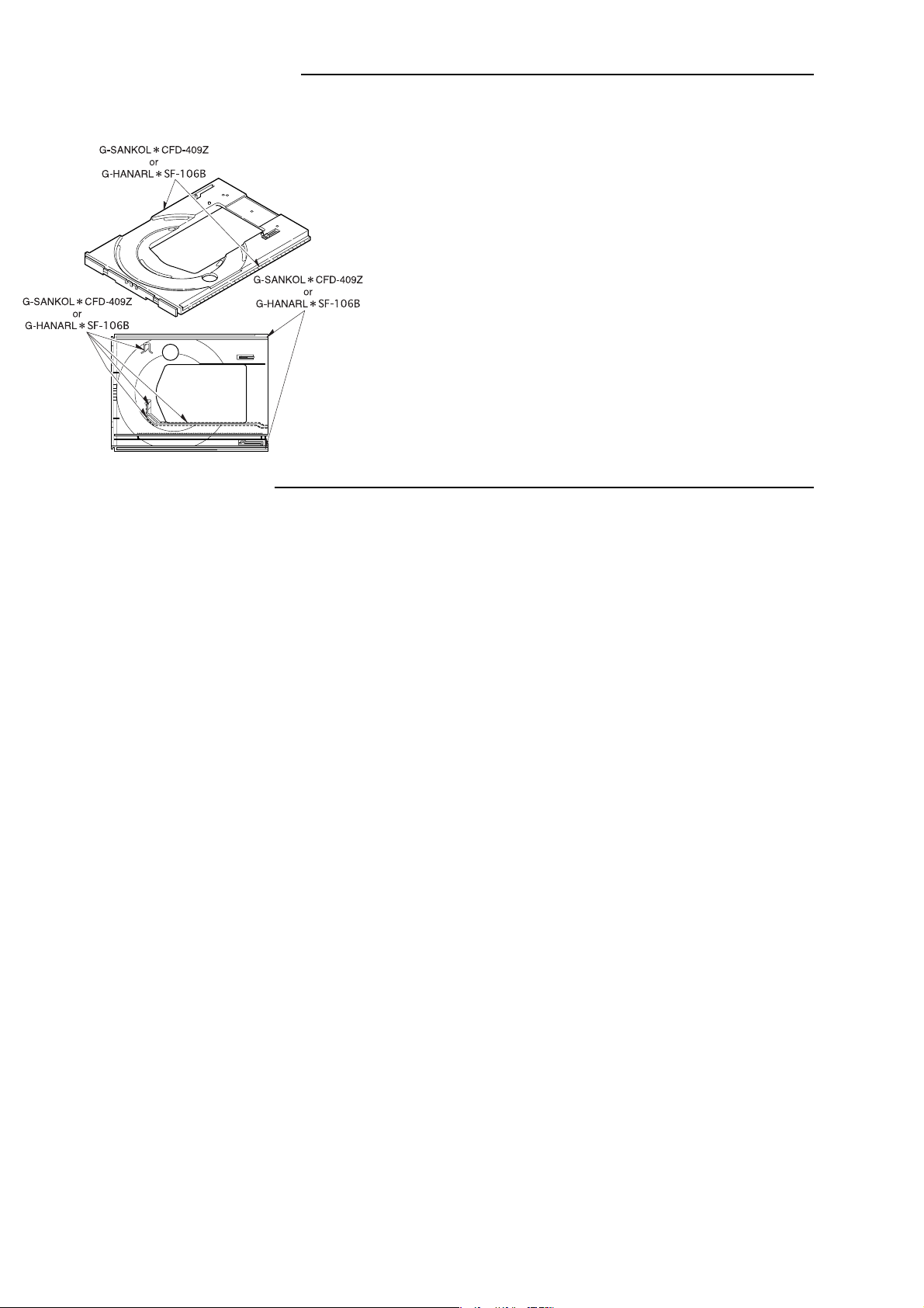
MECHANISM REPLACEMENT
5. Tray parts.
SOFTWARE INSTRUCTION
A. How to upgrade software
1. Put CD-R to disc tray, then close the disc tray, the software
upgrade beginning automatically, OSD and VFD will show "UPDATE";
2. In order to avoid software updated fail ,please donít press any key
when software upgrading;
3. When software upgrade finished, disc tray will open automatically.
please don't power off the unit at once, waiting for 15 sec, the unit will
go to STANDBY status automatically, at this time, power off the unit,
then power on the unit, the software upgrade finished.
B. How to show version number and region code
1. No disc status;
2. Press STOP and POWER key in the same time, then press PREV key
on time, OSD will show software version number and region code.
C. How to do EEPROM
1. NO DISC status;
2. Press STOP and POWER key in the same time, then press PREV key
2 times continually, OSD will show STRATFINISH EEPROM
CLR/FINISH EEPROM CLR.
(CD-ROM Parts code : 0PRADC712110A)
- 3 -
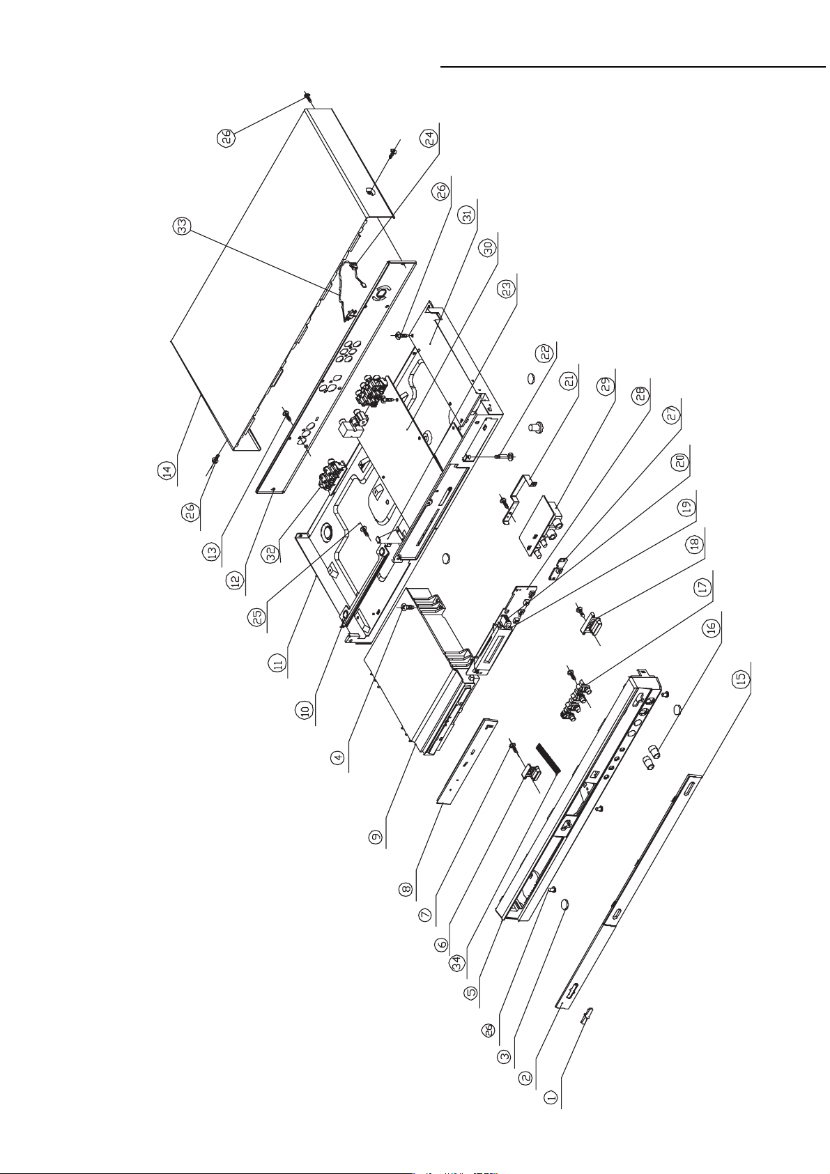
EXPLODED VIEW (CABINET & CHASSIS)
- 4 -

PARTS LIST
PRODUCT SAFETY NOTICE
EACH PRECAUTION IN THIS MANUAL SHOULD BE FOLLOWED DURING SERVICING. COMPONENTS IDENTIFIED WITH THE
!!
IEC SYMBOL
PERFORMANCE CAN BE OF SPECIAL SIGNIFICANCE. WHEN REPLACING A COMPONENT IDENTIFIED BY
REPLACEMENT PARTS DESIGNATED, OR PARTS WITH THE SAME RATINGS OF RESISTANCE, WATTAGE OR VOLTAGE THAT
ARE DESIGNATED IN THE PARTS LIST IN THIS MANUAL. LEAKAGE-CURRENT OR RESISTANCE MEASUREMENTS MUST BE
MADE TO DETERMINE THAT EXPOSED PARTS ARE ACCEPTABLY INSULATED FROM THE SUPPLY CIRCUIT BEFORE
RETURNING THE PRODUCT TO THE CUSTOMER.
CAUTION : Regular type resistors and capacitors are not listed. To know those values, refer to the schematic diagram.
!
IN THE PARTS LIST AND THE SCHEMATIC DIAGRAM DESIGNATED COMPONENTS IN WHICH SAFETY AND
!!
!
, USE ONLY THE
Regular type resistors are less than 1/4 W carbon type and chip resistors.
Regular type capacitors are less than 50 V and less than 1000 µF type of Ceramic type and Electrical type.
PACKING & ACCESSORIES
REF.NO. PART NO. DESCRIPTION
645 067 9049 GIFT BOX
645 067 4044 INSTRUCTION MANUAL
645 067 4204 POLYFOAM RIGHT
645 067 4211 POLYFOAM LEFT
645 065 7290 POLYBAG,AC CORD WIRE
645 065 7290 POLYBAG,RCA CABLE
645 064 9745 POLYBAG,UNIT
645 064 9752 POLYBAG,IB
645 064 0919 SOFT BAG
645 064 9523 REMOTE CONTROL
645 064 0711 RCA CABLE
645 064 9677 CONVERSION PLUG
33 645 064 8434 AC LINE CORD
CABINET & CHASSIS
REF.NO. PART NO. DESCRIPTION
1 645 064 0674 LOGO,SANYO
2 645 067 4129 DVD DOOR LENS
3 645 064 0704 RUBBER
4 645 067 4198 SCREW 3X8,
BOTTOM CAB TO LOADER
5 645 067 4068 FRONT PANEL
6 645 067 4075 KNOB OPEN
7 645 067 4181 SCREW 2.5X6,
FRONT PANEL TO KNOB
8 645 067 4051 DVD DOOR
10 645 067 4143 BRACKET,FOR FRONT CAB
11 645 067 4150 BOTTOM CABINET
12 645 067 9643 REAR CABINET
13 645 060 6779 SCR 3X8,BACK CAB TO MAIN PCB
14 645 064 0759 TOP COVER
15 645 067 4112 DISPLAY LENS
16 645 067 4105 KNOB MIC
17 645 067 4082 KNOB FUNCTION
18 645 067 4099 KNOB POWER
19 645 067 4228 VFD HOLDER,FOR VFD
20 645 067 4235 SPONGE EVA
21 645 067 4136 PHONE BRACKET
22 645 064 0780 SPACER
23 645 064 0773 BRACKET
24 645 063 9975 BUSHING AC LINE
25 645 063 3430 SCR 3X10,
FRONT PANEL TO BRACKET
26 645 064 0797 SCREW 3X6,TO BRACKET
34 645 067 3986 COPPER SHEET,
FRO FRONT PANEL
ELECTRICAL WIRE
REF.NO. PART NO. DESCRIPTION
645 064 0377 24P FFC CABLE UL2069,
DVD PICK UP TO CN801
645 064 0360 6P FFC CABLE UL20696,
DVD PICK UP TO CN802
645 064 0414 5P FLAT CABLE AWG26,
DVD LOADER TO CN803
SWITCH P.W.BOARD ASSY
REF.NO. PART NO. DESCRIPTION
27 614 329 8113 ASSY,PWB,SWITCH(Only initial)
TA203 645 060 4874 SW TACT,JW1-6,9-11
VFD P.W.BOARD ASSY
REF.NO. PART NO. DESCRIPTION
28 614 329 8106 ASSY,PWB,VFD(Only initial)
CN501 645 064 0384 14P FLAT CABLE AWG26,TO MAIN
CN902
D0501 645 060 4775 DIODE 1N4148
D0502 645 060 4775 DIODE 1N4148
IC501 645 067 4006 IC PT6312,VFD DRIVE IC
Q0501 645 063 2457 TR 2SC1623
SN501 645 064 0469 REMOTE SENSOR B38F,
IRT SENSOR
TA201 645 060 4874 SW TACT,B.SKIP
TA202 645 060 4874 SW TACT,F.SKIP
TA204 645 060 4874 SW TACT,STOP
TA205 645 060 4874 SW TACT,OPEN,CLOSE
TA206 645 060 4874 SW TACT,PLAY,PAUSE
VD501 645 064 0582 VFD,VFD501
ZD501 645 063 9951 ZENER DIODE 3.6V
645 067 4013 2P WIRE AWG26 UL2468,
CON1-1 TO CON1-2
645 067 4228 VFD HOLDER,FOR VFD
645 067 4235 SPONGE EVA
MIC P.W.BOARD ASSY
REF.NO. PART NO. DESCRIPTION
29 614 330 1035 ASSY,PWB,MIC(Only initial)
MIC01 645 064 9554 PHONE JACK,JY-6315-01-090
MIC02 645 064 9554 PHONE JACK,JY-6315-01-090
N301A 645 066 7770 SHIELDER CABLE AWG28
VR302 645 064 9769 CONTROL ROTARY,FOR VOLUME
VR303 645 064 9769 CONTROL ROTARY,FOR ECHO
MIAN P.W.BOARD ASSY
REF.NO. PART NO. DESCRIPTION
30 614 329 9011 ASSY PWB,MAIN(Only initial)
CN401 645 060 5086 8P CONNECTOR
CN405 645 063 2433 4P CONNECTOR
CN406 645 060 5062 3P CONNECTOR
CN801 645 064 0438 24P CONNECTOR
CN802 645 064 0070 6P CONNECTOR
CN803 645 063 2440 5P CONNECTOR
CN901 645 064 0308 14P CONNECTOR
CN902 645 064 0308 14P CONNECTOR
D0301 645 064 0056 DIODE CHIP 1N4148W,BAV16W
D0302 645 064 0056 DIODE CHIP 1N4148W,BAV16W
D0303 645 064 0056 DIODE CHIP 1N4148W,BAV16W
D0401 645 064 0056 DIODE CHIP 1N4148W,BAV16W
D0404 645 064 0056 DIODE CHIP 1N4148W,BAV16W
D0405 645 064 0056 DIODE CHIP 1N4148W,BAV16W
D0406 645 064 0056 DIODE CHIP 1N4148W,BAV16W
D0408 645 064 0056 DIODE CHIP 1N4148W,BAV16W
D0409 645 064 0056 DIODE CHIP 1N4148W,BAV16W
D0410 645 064 0056 DIODE CHIP 1N4148W,BAV16W
D0411 645 064 0056 DIODE CHIP 1N4148W,BAV16W
D0412 645 064 0056 DIODE CHIP 1N4148W,BAV16W
- 5 -

PARTS LIST
REF.NO. PART NO. DESCRIPTION
D0413 645 064 0056 DIODE CHIP 1N4148W,BAV16W
D0414 645 064 0056 DIODE CHIP 1N4148W,BAV16W
D0416 645 064 0056 DIODE CHIP 1N4148W,BAV16W
D0417 645 064 0056 DIODE CHIP 1N4148W,BAV16W
D0419 645 064 0056 DIODE CHIP 1N4148W,BAV16W
D0422 645 064 0056 DIODE CHIP 1N4148W,BAV16W
D0801 645 064 0056 DIODE CHIP 1N4148W,BAV16W
D0804 645 064 0056 DIODE CHIP 1N4148W,BAV16W
FB101 645 064 0018 CHIP BEAD 80OHM
FB102 645 063 2518 BEAD FERRITE 100MHZ
FB103 645 064 0018 CHIP BEAD 80OHM
FB104 645 064 0018 CHIP BEAD 80OHM
FB107 645 064 0018 CHIP BEAD 80OHM
FB301 645 064 0018 CHIP BEAD 80OHM
FB302 645 064 0018 CHIP BEAD 80OHM
FB401 645 064 0018 CHIP BEAD 80OHM
FB406 645 064 0018 CHIP BEAD 80OHM
FB407 645 064 0018 CHIP BEAD 80OHM
FB408 645 064 0018 CHIP BEAD 80OHM
FB409 645 064 0018 CHIP BEAD 80OHM
FB410 645 064 0018 CHIP BEAD 80OHM
FB411 645 064 0018 CHIP BEAD 80OHM
FB412 645 064 0018 CHIP BEAD 80OHM
FB413 645 064 0018 CHIP BEAD 80OHM
FB414 645 064 0018 CHIP BEAD 80OHM
FB415 645 064 0018 CHIP BEAD 80OHM
FB801 645 063 2518 BEAD FERRITE 100MHZ
FB802 645 064 0018 CHIP BEAD 80OHM
FB901 645 063 2518 BEAD FERRITE 100MHZ
FB902 645 063 2518 BEAD FERRITE 100MHZ
FB903 645 063 2518 BEAD FERRITE 100MHZ
FB904 645 064 0018 CHIP BEAD 80OHM
FB905 645 064 0018 CHIP BEAD 80OHM
FB907 645 063 2518 BEAD FERRITE 100MHZ
FB908 645 064 0018 CHIP BEAD 80OHM
FB909 645 064 0018 CHIP BEAD 80OHM
FB910 645 064 0018 CHIP BEAD 80OHM
FB911 645 064 0018 CHIP BEAD 80OHM
FB912 645 064 0018 CHIP BEAD 80OHM
FB913 645 064 0018 CHIP BEAD 80OHM
FB914 645 064 0018 CHIP BEAD 80OHM
FB915 645 064 0018 CHIP BEAD 80OHM
FB916 645 063 2518 BEAD FERRITE 100MHZ
FB917 645 063 2518 BEAD FERRITE 100MHZ
FB918 645 064 0018 CHIP BEAD 80OHM
JK402 645 064 0520 RCA JACK,RCA-213
JK403 645 064 0513 RCA JACK,RCA-108D5
JK404 645 064 0506 RCA+DIN JACK
L0401 645 064 0292 CHIP INDUCTOR
L0402 645 064 0285 CHIP INDUCTOR
L0403 645 064 0285 CHIP INDUCTOR
L0404 645 064 0285 CHIP INDUCTOR
L0801 645 064 0018 CHIP BEAD 80OHM
Q0301 645 063 2457 TR 2SC1623
Q0302 645 063 2488 TR 2SA733
Q0303 645 063 2457 TR 2SC1623
Q0304 645 063 2457 TR 2SC1623
Q0305 645 063 2488 TR 2SA733
Q0306 645 063 2457 TR 2SC1623
Q0307 645 063 2457 TR 2SC1623
Q0402 645 063 2457 TR 2SC1623
Q0403 645 063 2457 TR 2SC1623
Q0405 645 063 2488 TR 2SA733
Q0406 645 063 2488 TR 2SA733
Q0410 645 063 2488 TR 2SA733
Q0801 645 064 0278 TRANSISTOR CM5783GR
Q0802 645 064 0278 TRANSISTOR CM5783GR
Q0803 645 064 0278 TRANSISTOR CM5783GR
Q0804 645 064 0278 TRANSISTOR CM5783GR
Q0805 645 064 0322 TRANSISTOR CM5051-0
Q0806 645 064 0261 TRANSISTOR DDTC114EC
Q0807 645 064 0322 TRANSISTOR CM5051-0
RN101 645 064 0339 RESISTOR,RES ARRAY
RN102 645 064 0346 RESISTOR,RES ARRAY
REF.NO. PART NO. DESCRIPTION
U0101 645 064 0087 IC IMP809SEUR-T,
MICRO CTL PWR SUPPLY
U0102 645 064 0162 IC ZR36748P,
INTERGATED DVD DECODER
U0103 645 065 4572 IC VT361716T-6
U0104 645 065 8624 IC SST39VF800,WITH SOFTWARE
U0105 645 064 0155 IC AT24C02N-10SI-2.7
U0301 645 064 9516 IC PT2399S,ECHO PROCESSOR
U0302 645 064 0100 IC RC4558
U0303 645 064 0100 IC RC4558
U0401 645 064 0100 IC RC4558
U0403 645 064 0131 IC WM8761ED,STEREO ADC
U0404 645 064 0230 IC 74HCU04D,COMS INVERTER IC
U0405 645 064 0223 IC NC7SZ157P6X,
2 I/P N-INVERTING MULTIP
U0801 645 064 0124 IC LA6560,MOTOR DRIVER
U0802 645 064 0094 IC LM358MX,
LOW PWR DUAL OP AMP
U0803 645 064 0216 IC IC41LV16256-35T,
256KX16 (4MBIT) D-RAM
U0804 645 064 0179 IC LC78663NRW,
DVD FRONT END IC
U0805 645 064 0148 IC LA9703W,DVD PLAYERS RF AMP
U0901 645 064 0247 IC FS8860-18CJ,
VOLT. LDO LINEAR REG.
U0902 645 064 0193 IC B1117N
U0903 645 064 0193 IC B1117N
U0904 645 064 0254 IC FS8860-25CJ,
VOLT. LDO LINEAR REG.
Y0101 645 064 0698 CRYSTAL 27MHZ
Y0801 645 060 6519 CRYSTAL 16.9344MHZ
POWER P.W.BOARD ASSY
REF.NO. PART NO. DESCRIPTION
31 614 329 9028 ASSY PWB,POWER(Only initial)
C0101 645 064 0988 CONDUCTOR SAFETY
C0102 645 064 8496 ELECT
C0106 403 135 7409 ELECT 22U M 50V
C0107 645 064 0995 CONDUCTOR SAFETY
C0108 645 064 0995 CONDUCTOR SAFETY
C0109 645 064 0995 CONDUCTOR SAFETY
C0203 403 135 4705 ELECT 2200U M 10V
C0204 403 135 4507 ELECT 1000U M 10V
C0205 403 125 5507 ELECT 1000U M 16V
CN102 645 064 0315 4P CONNECTOR,C0N102
CN201 645 064 0384 14P FLAT CABLE AWG26,CON201
D0101 645 063 2228 DIODE 1N4007
D0102 645 063 2228 DIODE 1N4007
D0103 645 063 2228 DIODE 1N4007
D0104 645 063 2228 DIODE 1N4007
D0105 645 063 9937 DIODE UF4007
D0107 645 063 9920 DIODE FR103
D0202 645 064 0445 DIODE 1N5822
D0204 645 063 9944 RECITIFER 1N5819
D0205 645 063 9920 DIODE FR103
D0206 645 063 9920 DIODE FR103
D0207 645 063 9920 DIODE FR103
F0001 645 064 8458 FUSE
IC101 645 064 0452 IC KA5M02659RN,
POWER SWITCH IC
IC102 645 064 0476 IC SFH615A-3,OPT SENSOR
IC201 645 063 2662 IC TL431,VOLT. REGULATOR
L0202 645 064 0483 COIL 10UH
L0203 645 064 0483 COIL 10UH
L0204 645 064 0483 COIL 10UH
L0205 645 060 4805 CHOKE COIL 10UH
R0002 645 066 7725 RESISTOR 1 OHM 1/4W
T0101 645 064 0421 AC FILTER 25MH
T0102 645 064 0735 POWER TRANSFORMER
ZD201 645 063 9968 ZENER DIODE 12V
645 060 5222 FUSE CLIP
- 6 -
 Loading...