

Page 1

SANYSANY
SANY
SANYSANY
Model DS25520 (Chassis 25520-00/01)Model DS25520 (Chassis 25520-00/01)
Model DS25520 (Chassis 25520-00/01)
Model DS25520 (Chassis 25520-00/01)Model DS25520 (Chassis 25520-00/01)
Model DS25520 (Chassis 25520-01)
OO
O
OO
Page 2
PP
aa
gg
e 1e 1
g
e 1
gg
e 1e 1
SET 4737 SET 4737
SET 4737
SET 4737 SET 4737
P
a
PP
aa
TUNER INFORMATION
TUNER TUNER
TUNER
TUNER TUNER
PinPin
Pin
PinPin
(1) AGC 2.3V 2.4V 2.8V
(3) EN 0V 0V 0V
(4) SCL 4.2V 4.2V 4.2V
(5) SDA 4.2V 4.2V 4.2V
(6) MB 5.0V 5.0V 5.0V
(7) PB 5.0V 5.0V 5.0V
(9) TB 33.6V 33.6V 33.6V
(11) IF 0V 0V 0V
NOTE: VHF Low Band voltages taken on channel 2.
VHF LoVHF Lo
VHF Lo
VHF LoVHF Lo
VHF High Band voltages taken on channel 7.
UHF Band voltages taken on channel 14.
VV
OLOL
TT
AA
V
VV
w Bandw Band
w Band
w Bandw Band
Test equipment listed by participating manufacturer illustrates typical or equivalent equipment used by Sams engineers to obtain
measurements. This equipment is compatible with most types used by field service technicians.
EquipmentEquipment
Equipment
EquipmentEquipment
Oscilloscope SC3100
Generators
RGB CM2125
Multiburst Signal VG91
Color Bar VG91
TV Stereo VG91
Digital VOM SC3100
Frequency Meter SC3100
Hi-Voltage Probe HP200
Accessory Probes TP212
GE CHARGE CHAR
OL
T
A
GE CHAR
OLOL
TT
AA
GE CHARGE CHAR
VHF High BandVHF High Band
VHF High Band
VHF High BandVHF High Band
TT
T
TT
UHF BandUHF Band
UHF Band
UHF BandUHF Band
TEST EQTEST EQ
TEST EQ
TEST EQTEST EQ
Sencore No.Sencore No.
Sencore No.
Sencore No.Sencore No.
TUNER TUNER
TUNER
TUNER TUNER
TERMINAL GUIDETERMINAL GUIDE
TERMINAL GUIDE
TERMINAL GUIDETERMINAL GUIDE
t
t
(4)
t
t
(6)
t
t
t
t
UIPMENTUIPMENT
UIPMENT
UIPMENTUIPMENT
EquipmentEquipment
Equipment
EquipmentEquipment
Isolation Transformer PR570
Capacitance Analyzer LC102
CRT Analyzer CR7000
AC Leakage Tester PR570
Inductance Analyzer LC102
Flyback Yoke Tester TVA92
Field Strength Meter SL753
Transistor Tester TF46
Horizontal Analyzer HA-2500
Video Analyzer VG91, TVA92
Sencore No.Sencore No.
Sencore No.
Sencore No.Sencore No.
(1)
(3)
(5)
(7)
(9)
(11)
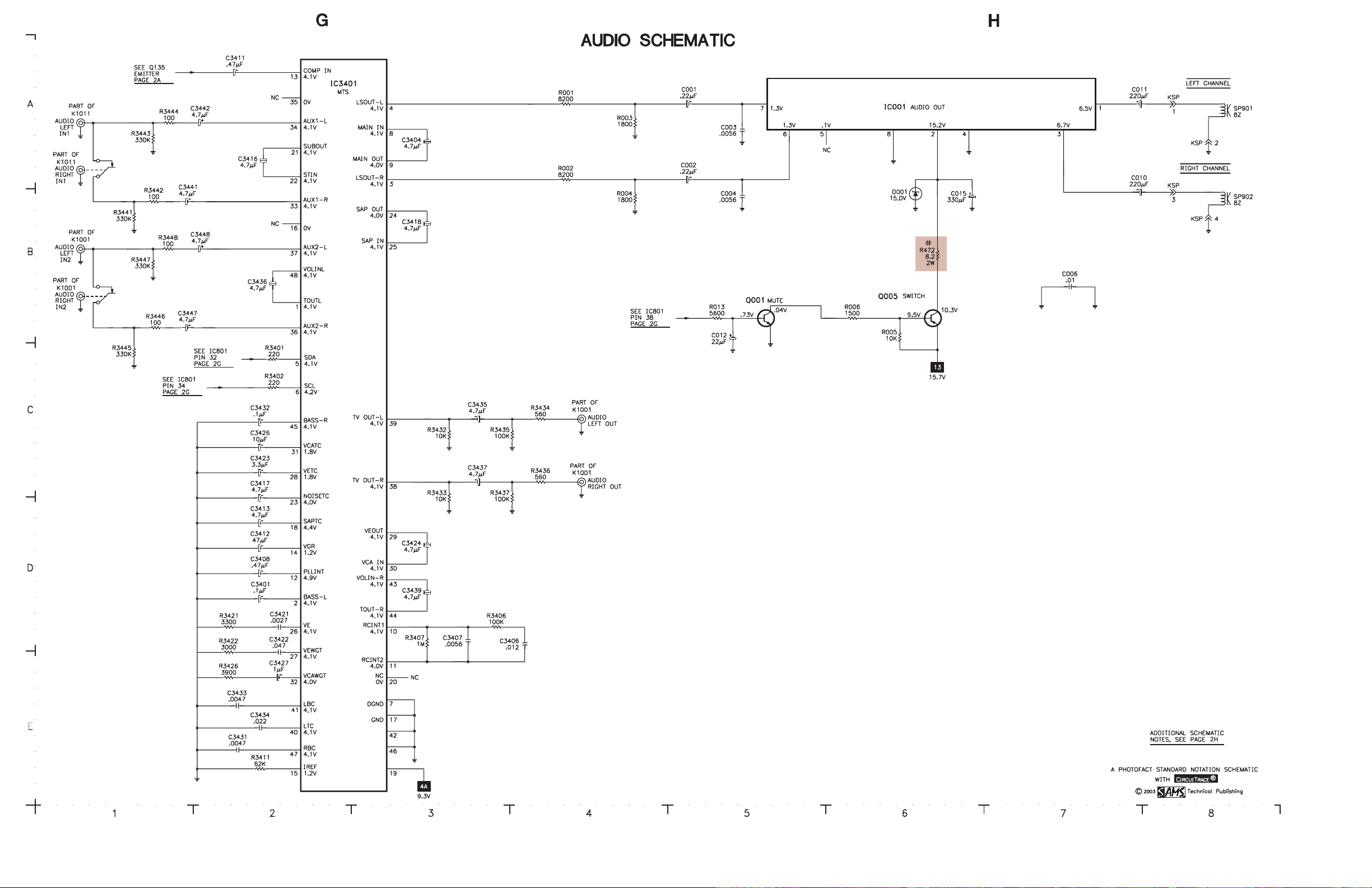
SCHEMASCHEMA
SCHEMA
SCHEMASCHEMA
A1901 A33
C001 A5
C002 B5
C003 A5
C004 B5
C006 B7
C010 B7
C011 A7
C012 C5
C015 B6
C101 E32
C103 B40
C106 C9
C131 B11
C133 B11
C134 B11
C137 A11
C141 C9
C142 B11
C143 B9
C146 E32
C147 E32
C151 B10
C153 B10
C161 B9
C211 B17
C212 C18
C221 A18
C252 B19
C253 C19
C256 B19
C257 D32
C258 D32
C272 C19
C274 C19
C284 B19
C285 B19
C401 E9
C402 E9
C403 D9
C404 E12
C405 D9
C406 E13
C407 E13
C408 E13
C411 E15
C416 E16
C417 E16
C421 D11
C427 D11
C441 C18
C471 E27
C473 E15
C482 E27
C484 E11
C487 E28
C489 D31
C493 D19
C497 E31
C502 D14
C503 D13
C504 D13
C505 D11
C506 D13
C508 C13
C509 D11
C511 D15
C516 D14
C601 A25
C603 A27
TIC COMPONENT LOCATIC COMPONENT LOCA
TIC COMPONENT LOCA
TIC COMPONENT LOCATIC COMPONENT LOCA
C604 A27
C606 B26
C608 B29
C609 A28
C612 C26
C613 C27
C614 D26
C625 A30
C626 B30
C628 A32
C629 B32
C631 A26
C632 B28
C634 D29
C683 C30
C689 B31
C693 D30
C701 B22
C711 C22
C721 A23
C742 D24
C801 E32
C806 E31
C809 C37
C810 D37
C811 A36
C822 E32
C829 C35
C835 B35
C841 A20
C842 A20
C843 A19
C853 C34
C854 C35
C856 E37
C857 E37
C858 C36
C862 C36
C1001 B13
C1002 A13
C1051 A15
C1052 B15
C1059 A15
C1071 D31
C1080 D32
C1081 D32
C1902 E31
C3401 D2
C3404 A3
C3406 D4
C3407 D3
C3408 D2
C3411 A2
C3412 D2
C3413 D2
C3414 D32
C3416 A2
C3417 D2
C3418 B3
C3421 D2
C3422 E2
C3423 C2
C3424 D3
C3426 C2
C3427 E2
C3431 E2
C3432 C2
C3433 E2
C3434 E2
C3435 C3
TION GUIDETION GUIDE
TION GUIDE
TION GUIDETION GUIDE
C3436 B2
C3437 C3
C3439 D3
C3441 B1
C3442 A1
C3447 C1
C3448 B1
D001 B6
D101 B39
D351 E10
D408 A32
D421 D11
D422 E11
D428 B34
D429 B34
D471 E27
D481 E27
D482 E11
D483 E26
D486 D31
D487 D19
D490 E31
D501 D14
D502 D15
D503 E28
D601 A27
D602 A27
D603 A27
D604 A27
D611 C28
D612 B26
D613 C27
D614 C27
D624 B29
D625 A30
D627 D30
D629 B30
D680 C31
D683 B32
D693 D29
D801 B35
D834 C34
D836 C34
D843 C35
D1001 B13
D1002 A13
D1051 A15
D1052 B15
D1059 A15
D1901 E32
D1902 B39
F601 A25
IC001 A6
IC101 A11
IC101 B11
IC101 B19
IC101 D10
IC501 D14
IC601 D26
IC681 E30
IC801 B36
IC802 D34
IC1081 A14
IC1081 A16
IC1081 B16
IC3401 A2
K1001 B1
K1001 B13
K1001 C4
K1001 C4
K1011 A1
K1011 A13
K1051 A14
L164 B13
L401 E14
L404 E12
L602 C28
L611 C28
L612 C28
L623 B29
L625 A29
L801 E31
L811 D37
L812 C37
L821 E31
L851 E31
L901 B26
L902 D16
L1901 E31
LF601 A25
PS601 A26
Q001 B5
Q005 B6
Q135 A12
Q202 B13
Q208 C33
Q401 E12
Q402 E14
Q486 D31
Q490 E31
Q601 B28
Q611 B27
Q612 C27
Q613 C27
Q627 B31
Q635 D29
Q681 C31
Q693 D29
Q695 D29
Q701 B23
Q711 C23
Q721 A23
Q831 A35
Q901 B24
Q1071 A17
R001 A4
R002 B4
R003 A4
R004 B4
R005 C6
R006 B6
R013 B5
R106 B39
R107 B39
R131 A11
R133 B11
R137 A12
R142 C10
R143 B9
R151 C10
R161 B10
R162 B9
R163 B12
R164 B13
R166 B12
R167 B12
R201 B13
R208 C34
R209 C33
R212 C18
R251 C19
R252 C19
R272 B19
R273 C19
R274 C19
R276 C19
R281 D10
R284 B19
R287 B21
R288 B21
R289 B21
R321 A20
R353 E10
R400 D12
R401 E9
R402 E9
R404 E12
R405 D9
R406 E13
R407 E13
R411 E14
R416 E14
R421 E11
R422 E11
R423 D11
R426 D11
R428 B34
R430 E12
R441 C18
R442 C18
R443 C10
R444 C11
R449 D9
R471 E26
R472 B6
R481 E27
R482 E11
R483 E26
R485 D19
R486 D30
R487 D30
R488 E31
R489 D30
R491 D19
R492 D19
R493 D19
R494 D19
R495 D31
R497 A24
R499 E31
R503 D12
R504 D13
R505 D13
R506 D13
R507 D13
R508 D13
R509 D13
R511 D15
R513 D15
R517 D14
R518 D14
R601 A26
R602 B26
R603 A28
R604 B29
R606 B27
R607 C27
R608 C27
R609 C27
R611 C28
R612 B28
R613 D28
R614 C27
R615 D28
R616 C27
R617 D27
R618 C26
R619 D26
R627 B31
R628 C31
R629 C30
R630 A31
R631 D29
R632 D29
R634 D29
R683 C30
R691 B30
R692 D30
R693 D29
R694 D29
R695 D29
R701 B23
R703 B22
R704 B22
R706 B23
R707 B23
R711 C23
R713 C22
R714 C22
R716 C23
R717 C23
R721 B23
R723 A22
R724 A22
R726 A23
R727 A23
R803 B11
R804 B11
R806 D37
R807 D35
R808 D35
R809 C37
R810 B36
R813 A35
R814 A35
R816 A34
R823 E35
R829 E36
R831 C35
R833 C34
R835 B35
R842 B38
R843 C38
R844 B38
R846 B37
R847 B37
R848 C37
R849 B37
R851 E37
R852 B35
R853 C34
R854 C35
R856 D38
R857 C38
R858 A37
R862 C35
R864 C35
R881 D37
R882 C37
R883 E37
R884 E37
R886 E37
R1001 B13
R1002 A13
R1003 A13
R1004 A13
R1006 B13
R1007 B13
R1051 A15
R1052 B14
R1053 A15
R1054 A15
R1059 A15
R1071 A17
R1073 A16
R1081 B16
R1082 B14
R1083 B15
R1084 B15
R1901 B34
R1902 B34
R1903 B33
R1904 B33
R1905 B33
R1906 B33
R1907 B33
R1909 A35
R1910 B34
R3401 C2
R3402 C2
R3406 D3
R3407 D3
R3411 E2
R3421 D2
R3422 E2
R3426 E2
R3432 C3
R3433 D3
R3434 C4
R3435 C3
R3436 C4
R3437 D3
R3441 B1
R3442 B1
R3443 A1
R3444 A1
R3445 C1
R3446 C1
R3447 B1
R3448 B1
RL601 A26
RL601 B32
SP901 A8
SP902 B8
SW1901 B33
SW1902 B33
SW1903 B33
SW1904 B33
SW1905 B33
SW1906 C33
T151 A10
T401 E13
T402 D17
T402 E25
T601 A29
W601 A25
X141 B9
X161 B13
X251 B18
X801 B35
Page 3

SET 4737 PSET 4737 P
SET 4737 P
SET 4737 PSET 4737 P
aa
gg
e 1e 1
a
g
e 1
aa
gg
e 1e 1
MISCELLANEOUS ADJUSTMENTS
B+ CHECKB+ CHECK
B+ CHECK
B+ CHECKB+ CHECK
Connect a digital DC voltmeter to the cathode of D625. Set brightness and picture
to minimum. With AC line set to 120VAC, B+ should read 130V ±2.0V.
HIGH HIGH
VV
OLOL
TT
AA
HIGH
V
HIGH HIGH
VV
Tune in a picture. Set customer controls to minimum. Connect a high voltage probe
to CRT anode. High voltage should measure 26kV to 28kV.
ENTERING SERENTERING SER
ENTERING SER
ENTERING SERENTERING SER
Disconnect the AC power cord. While pressing the menu button on the front of the
set, connect the AC power cord. Use the channel up and down buttons to select the
service number. Use volume up and down buttons to change the value. Press the
menu button to exit the service mode.
HORIZONTHORIZONT
HORIZONT
HORIZONTHORIZONT
Tune in a crosshatch pattern. Enter the service mode and select service item number
47 EWD. Adjust for the proper horizontal width.
HORIZONTHORIZONT
HORIZONT
HORIZONTHORIZONT
Tune in a crosshatch pattern. Enter the service mode and select service item number
03 HP. Adjust for the best horizontal centering.
RF ARF A
GC DELAGC DELA
RF A
GC DELA
RF ARF A
GC DELAGC DELA
Tune in a picture. Enter the service mode and select service number 42 RAD.
Adjust where no snow (noise) appears in picture.
VERVER
TICAL SIZETICAL SIZE
VER
TICAL SIZE
VERVER
TICAL SIZETICAL SIZE
Tune in a crosshatch pattern. Enter the service mode and select service item number
04 VS. Adjust for proper vertical size and best vertical linearity.
VERVER
TICAL CENTERINGTICAL CENTERING
VER
TICAL CENTERING
VERVER
TICAL CENTERINGTICAL CENTERING
Tune in a crosshatch pattern. Check that the pattern is centered. If too low, replace
resistor R513 1000 ohms 1/2W with a 470 ohms 1W. If too high, remove resistor
R513 1000 ohms 1/2W.
VCOVCO
VCO
VCOVCO
VCO must be adjusted after IC101, IC802, or T151 is replaced. Tune in a picture.
Connect positive lead of a digital voltmeter to pin 58 of IC101 and the negative lead
to TE7. Adjust T151 to obtain a reading of 3.6V ± 0.2V.
VIDEO LEVELVIDEO LEVEL
VIDEO LEVEL
VIDEO LEVELVIDEO LEVEL
Tune in a color bar pattern. Set picture and brightness to normal. Connect an
oscilloscope to the emitter of Q202, and the negative lead to ground. Enter the
service mode and select service number 46 VL. Adjust for 1.0Vp-p ±0.1Vp-p
waveform on the oscilloscope.
GRAGRA
Y SCALEY SCALE
GRA
Y SCALE
GRAGRA
Y SCALEY SCALE
Tune in an active channel. Enter the service mode. Set the value of service numbers
15 RB, 16 GB, and 17 BB to 0. Set the value of service numbers 18 RD and 20 BD
to 55. Set screen control, color, brightness, and picture to minimum. Adjust screen
control, if necessary, to obtain a barely visible horizontal line. Select service
number 73. Adjust the bias levels for a white line. Select service number 72 DRV
and adjust the drive values for normal black and white picture at all brightness
levels.
SUB BRIGHTNESSSUB BRIGHTNESS
SUB BRIGHTNESS
SUB BRIGHTNESSSUB BRIGHTNESS
Tune in a color bar pattern. Set picture and brightness to normal. Connect positive
lead of a digital voltmeter to TP51 and the negative lead to TP50. Enter the service
mode and select service number 53 SB. Adjust for 820mV ±10mV.
SUB COLOR,SUB COLOR,
SUB COLOR,
SUB COLOR,SUB COLOR,
Tune in a picture. Enter the service mode. Select service number 54 SCO. Adjust for
normal color level. Select service number 55 STI. Adjust for normal flesh tones.
Select service number 56 SSH. Adjust for contrast range.
OSD HORIZONTOSD HORIZONT
OSD HORIZONT
OSD HORIZONTOSD HORIZONT
Tune in a local channel. Enter the service mode and select service item number 59
HR. Adjust for centered on screen menu.
GE CHECKGE CHECK
OL
T
A
GE CHECK
OLOL
TT
AA
GE CHECKGE CHECK
AL AL
WIDTHWIDTH
AL
WIDTH
AL AL
WIDTHWIDTH
AL POSITIONAL POSITION
AL POSITION
AL POSITIONAL POSITION
YY
Y
YY
SUB SUB
SUB
SUB SUB
VICE MODEVICE MODE
VICE MODE
VICE MODEVICE MODE
TINTTINT
,,
SUB SHARPNESS SUB SHARPNESS
TINT
,
SUB SHARPNESS
TINTTINT
,,
SUB SHARPNESS SUB SHARPNESS
AL POSITIONAL POSITION
AL POSITION
AL POSITIONAL POSITION
SOUNDSOUND
SOUND
SOUNDSOUND
Tune in a local channel. Connect an oscilloscope to the base of Q135, and the
negative lead to ground. Enter the service mode and select service number 45 FL.
Adjust for 0.693Vp-p ± 0.07Vp-p waveform on the oscilloscope
INPUT LEVELINPUT LEVEL
INPUT LEVEL
INPUT LEVELINPUT LEVEL
Set generator to 1kHz audio frequency and L-R modulating signal. Connect an
oscilloscope to pin 38 of IC3401. Enter service mode and select the service item
number 60 ATT. Adjust for 0.7Vp-p waveform.
SEPSEP
ARAARA
SEP
SEPSEP
Set generator to pilot, 300Hz audio frequency, and left modulating signal. Connect
an oscilloscope to pin 38 of IC3401 and ground. Enter the service mode and select
service number 61 WDB. Adjust for minimum amplitude of the waveform. Set
generator to 8kHz audio frequency. Select service n umber 62 SPC and adjust for
minimum amplitude of the waveform.
PURITYPURITY
PURITY
PURITYPURITY
NOTE: Operate the receiver for 15 minutes to allow warm-up of CRT.
Use a degaussing coil to demagnetize the CRT. Tune in a green raster. Loosen the
clamp screw. Slide deflection yoke back as far as possible. Adjust purity tabs to
center the vertical green band. Slide the deflection yoke forward to produce a
uniform green screen. Tighten the clamp screw.
CONVERGENCECONVERGENCE
CONVERGENCE
CONVERGENCECONVERGENCE
Tune in a dot pattern. Loosen the clamp screw. Adjust the 4 pole magnets to
converge the red and blue dots at the center of the screen. Adjust the 6 pole magnets
to converge the red/blue dots over the green dots at the center of the screen.
NOTE: Rotate the two tabs of each set of magnets equally and opposite to converge
vertically and rotate both tabs in the same direction to converge horizontally. The 4
and 6 pole magnets interact, repeat adjustment until center convergence is correct.
Tune in a crosshatch pattern. Remove the tilt adjustment wedges between deflection
yoke and the CRT. Loosen the clamp screw. Tilt the deflection yoke up or down to
converge the vertical lines at the top and bottom of the screen and the horizontal
lines at the right and left sides of the screen. Tilt the deflection yoke to the right or
left to converge the horizontal line at the top and bottom of the screen and the
vertical line at the right and left sides of the screen. Repeat convergence procedure
if necessary to obtain best overall convergence. Replace the tilt adjustment wedges.
Tighten the clamp screw.
CRCR
CR
CRCR
IC802 REPLAIC802 REPLA
IC802 REPLA
IC802 REPLAIC802 REPLA
Perform the following adjustments after replacing IC802. Enter the service mode,
select service number 03 HP and set value to 14. Select service number 07 VLN and
set value to 13. Select service number 28 PRE and set value to 3. Select service
number 37 AF and set value to 1. Select service number 57 OPT and set value to
100. Select service number 58 OP2 and set value to 32. Press the menu button to
exit service mode.
TIONTION
ARA
TION
ARAARA
TIONTION
T NECK ASSEMBLT NECK ASSEMBL
T NECK ASSEMBL
T NECK ASSEMBLT NECK ASSEMBL
CEMENTCEMENT
CEMENT
CEMENTCEMENT
YY
Y
YY
SERVICE MODE ADJUSTMENT CHART
SerSer
vicevice
Ser
vice
SerSer
No.No.
No.
No.No.
01 HFR 0 - 63 29 29 2 9 Horizontal Frequency
02 AFC 0, 1 0 0 0 AFC Gain
03 HP 0 - 31 15 14 14 H-Position (H-Centering)
04 VS 0 - 127 64 64 51 Vertical Size
05 VPO 0 - 63 5 5 5 Vertical Position
06 VSP 0, 1 0 0 0 Vertical Set Up
07 VLN 0 - 31 18 13 13 Vertical Linearity
08 CRS 0 - 3 0 0 0 Cross B/W
09 GRY 0, 1 1 1 1 Gray Mode
10 VSC 0 - 31 8 8 8 Vertical S Correction
11 HBR 0 - 7 3 3 3 H BLK R
12 HBL 0 - 7 4 4 4 H BLK L
13 CD M 0, 1 0 0 0 CD Mode
14 VC 0 - 7 7 7 7 Vertical Compression
15 R B 0 - 255 0 0 0 Red Bias
16 GB 0 - 255 0 0 0 Green Bias
17 B B 0 - 255 0 0 7 Blue Bias
18 RD 0 - 127 64 64 8 5 Red Drive
19 GD 0 - 15 8 8 8 Green Drive
20 BD 0 - 127 64 64 62 Blue Drive
21 SBI 0 - 127 48 48 48 Sub Bias
22 OSD 0 - 3 3 3 3 OSD Contrast
23 POS 0, 1 0 0 0 Pre/Over/SW
24 FLS 0 - 7 1 1 1 Filter System
25 CKO 0 - 7 3 3 3 Color Killer Operation
26 GYA 0, 1 0 0 0 G-Y Angle
27 CRG 0 - 3 2 2 2 Coring Gain
28 PRE 0 - 3 1 3 3 Pre Shoot Adjust
29 WP 0, 1 0 1 1 White Peak Limiter, 0 = On, 1 = Off
30 FSW 0, 1 0 0 0 FBP Blanking Switch
31 VBL 0, 1 0 0 0 Vertical Blanking Switch
32 BSG 0 - 3 2 2 2 Black Stretch Gain
33 BSS 0 - 3 1 1 1 Black Stretch Start
34 DCR 0 - 3 1 1 1 DC Reset
35 YGM 0 - 3 1 1 1 Y Gamma
36 CB P 0, 1 0 0 0 C Bypass
37 AF 0, 1 0 1 1 Auto Flesh, 0 = Off, 1 = On
38 BAT 0 - 7 4 4 4 Bright ABL Threshold
39 MSD 0, 1 0 0 0 Mid Stop Def
40 ABL 0, 1 0 0 0 ABL Defeat, 0 = On, 1 = Off
41 RYA 0 - 15 2 2 2 R-Y/B-Y Angle
42 RAD 0 - 63 15 15 37 RF AGC Delay
43 IAS 0, 1 0 0 0 IF AGC Switch, 0 = TV (Normal), 1 = AV (IF Gain Minimum)
44 FM M 0, 1 0 0 0 FM Mute
45 FL 0 - 31 15 15 10 FM Level
46 VL 0 - 7 4 4 5 Video Level
47 EWD 0 - 63 39 39 39 EW DC
48 EWA 0 - 63 30 30 30 EW Amp
49 EWT 0 - 63 34 34 34 EW Tilt
50 EWP 0 - 7 7 7 7 EW Corner Top
51 EWB - 8 8 8 EW Corner Bottom
52 HSC - 7 7 7 Horiz Size Comp
53 SB 0 - 63 32 3 2 31 Sub Brightness
54 SCO 0 - 31 7 7 7 Sub Color
55 STI 0 - 31 20 20 20 Sub Tint
56 SSH 0 - 15 12 12 12 Sub Sharpness
57 OPT 0 - 255 0 100 100 Option, data 1 should be set to 100, in binary 8 bit 01100100
58 OP2 0 - 255 0 32 32 Option, data 2 should be set to 32, in binary 8 bit 0 0100000
59 HR 0 - 63 27 27 27 OSD Horizontal Position
60 ATT 0 - 15 10 7 8 Attenuation
61 WDB 0 - 63 32 32 34 Wide Band
62 SPC 0 - 63 32 32 11 Spectral
63 SBO 0 - 255 5 5 5 Sub Bright Offset
64 PCO 0 - 63 40 40 40 PIP Color
65 PTI 0 - 63 40 40 40 PIP Tint
66 PUV 0 - 63 24 2 4 24 PIP Top Position
67 PDV 0 - 255 147 147 147 PIP Bottom Position
68 PLH 0 - 63 10 1 0 10 PIP Left Position
69 PRH 0 - 255 101 10 1 101 PIP Right Position
70 PCN 0 - 63 42 42 52 PIP Y Level
71 PBS 0 - 63 15 15 15 PIP BGP Phase
72 DRV 0 - 127 64 64 R 85 Red Drive, press 1 to decrease value and 3 to increase value.
73 - 0 - 255 0 0 0 Red Bias, press 1 to decrease value and 3 to increase value.
74 R00
Thru Thru
146 R72 0 - 255 - 0 0 -
vicevice
AdjustmentAdjustment
Adjustment
AdjustmentAdjustment
DRV 0 - 127 64 64 B 62 Blue Drive, press 7 to decrease value and 9 to increase value.
- 0 - 255 0 0 0 Green Bias, press 4 to decrease value and 6 to increase value.
- 0 - 255 0 0 0 Blue Bias, press 7 to decrease value and 9 to increase value.
VV
aluealue
V
alue
VV
aluealue
RangRang
Rang
RangRang
Initial RefInitial Ref
Initial Ref
ee
e
ee
Initial RefInitial Ref
VV
aluealue
V
alue
VV
aluealue
Initial SetInitial Set
Initial Set
Initial SetInitial Set
Up Up
VV
aluealue
Up
V
alue
Up Up
VV
aluealue
On-SetOn-Set
On-Set
On-SetOn-Set
VV
aluealue
V
alue
VV
aluealue
NotesNotes
Notes
NotesNotes
Page 4
SANY
SANYSANY
SANYSANY
O MODEL DS25520 (CHASSIS 25520-00/01)
O MODEL DS25520 (CHASSIS 25520-00/01)O MODEL DS25520 (CHASSIS 25520-00/01)
O MODEL DS25520 (CHASSIS 25520-00/01)O MODEL DS25520 (CHASSIS 25520-00/01)
SET 4737 PSET 4737 P
SET 4737 P
SET 4737 PSET 4737 P
aa
gg
e 1e 1
a
g
e 1
aa
gg
e 1e 1
Page 5

PP
aa
gg
e 2e 2
g
e 2
gg
e 2e 2
SET 4737 SET 4737
SET 4737
SET 4737 SET 4737
P
a
PP
aa
Page 6

SET 4737 PSET 4737 P
SET 4737 P
SET 4737 PSET 4737 P
aa
gg
e 2e 2
a
g
e 2
aa
gg
e 2e 2
Page 7

PP
aa
gg
e 2e 2
a
g
e 2
aa
gg
e 2e 2
SET 4737 SET 4737
SET 4737
SET 4737 SET 4737
P
PP
Page 8

SANY
SANYSANY
SANYSANY
O MODEL DS25520 (CHASSIS 25520-00/01)
O MODEL DS25520 (CHASSIS 25520-00/01)O MODEL DS25520 (CHASSIS 25520-00/01)
O MODEL DS25520 (CHASSIS 25520-00/01)O MODEL DS25520 (CHASSIS 25520-00/01)
SET 4737 PSET 4737 P
SET 4737 P
SET 4737 PSET 4737 P
aa
gg
e 2e 2
a
g
e 2
aa
gg
e 2e 2
Page 9

PP
aa
gg
e 3e 3
g
e 3
gg
e 3e 3
SET 4737 SET 4737
SET 4737
SET 4737 SET 4737
P
a
PP
aa
SET 4737 PSET 4737 P
SET 4737 P
SET 4737 PSET 4737 P
aa
gg
e 3e 3
a
g
e 3
aa
gg
e 3e 3
MAIN BOMAIN BO
MAIN BO
MAIN BOMAIN BO
ARD - ARD -
ARD -
ARD - ARD -
TT
OP OP
T
OP
TT
OP OP
MAIN BOMAIN BO
MAIN BO
MAIN BOMAIN BO
A101 I12
A1901 A4
C001 C11
C002 C11
C010 B12
C011 B11
C012 F7
C015 C12
C101 J11
C106 J11
C131 G10
C147 G11
C151 F12
C153 F12
C211 D12
C212 E11
C221 E11
C252 D11
C253 D11
C256 E11
C258 E11
C272 G10
C274 G10
C284 G10
C401 D10
C403 E10
C405 E10
C406 I5
C407 H5
C408 H4
C411 J4
C416 K4
C417 K4
C421 D11
C471 H2
C473 H6
C482 H3
C484 K7
C487 H4
C489 F6
C493 H2
C497 G8
C502 I8
C503 J8
C504 J9
C505 D10
C506 I8
C509 E9
C511 K5
C516 I8
C601 B1
C603 D3
C604 D2
C606 C1
C608 F3
C609 D1
C612 E1
VIEWVIEW
VIEW
VIEWVIEW
ARD - ARD -
ARD -
ARD - ARD -
TT
OP OP
VIEWVIEW
,,
VIEW
VIEWVIEW
GRIDTRA GRIDTRA
,
GRIDTRA
,,
GRIDTRA GRIDTRA
T
OP
TT
OP OP
C613 E2
C614 E1
C625 E5
C626 F5
C628 G6
C629 D5
C631 A3
C632 D4
C634 C4
C683 C5
C693 C5
C806 D7
C811 E7
C822 E8
C829 E8
C853 E7
C856 E7
C1001 J10
C1002 A9
C1051 J11
C1059 J9
C1081 J10
C1902 A3
C3401 B9
C3404 B9
C3408 B10
C3411 B11
C3412 B10
C3413 B10
C3414 B11
C3416 B11
C3417 B11
C3418 B10
C3424 C11
C3427 C10
C3432 C9
C3435 D9
C3436 B9
C3437 D10
C3439 C9
C3441 C11
C3442 C10
C3447 C10
C3448 C10
D001 B12
D101 I11
D351 D9
D408 H3
D421 D10
D422 G12
D428 J8
D429 H9
D471 H2
D481 H3
D482 J7
D483 H3
D486 E6
CE LOCACE LOCA
CE LOCA
CE LOCACE LOCA
D487 H2
D490 G7
D501 I7
D502 I8
D503 H4
D601 D3
D602 D3
D603 D2
D604 D2
D611 F2
D612 D4
D613 E2
D614 E2
D624 F5
D625 E5
D627 C4
D629 B5
D680 B4
D683 A4
D693 C4
D801 G8
D834 D8
D843 E8
D1001 J10
D1002 A9
D1051 J10
D1052 J11
D1901 A4
D1902 A9
F601 A1
IC001 B12
IC501 I7
IC601 D4
IC681 A5
IC802 E9
IC1081 I10
K1001 K9
K1011 A10
K1051 K10
KB K 6
KD C2
KS F9
KSP C12
KTP H1
KX K4
L164 E12
L401 H6
L404 H4
L602 E3
L611 F1
L612 E2
L623 F5
L625 E5
L801 E9
L811 F8
L812 F8
L821 D8
TION GUIDETION GUIDE
TION GUIDE
TION GUIDETION GUIDE
L851 D7
L1901 A4
LF601 A2
PS601 C3
Q001 F7
Q005 F7
Q135 F11
Q202 E12
Q208 D11
Q401 I4
Q402 J6
Q486 E6
Q490 G8
Q601 G2
Q611 E2
Q612 E1
Q613 E1
Q627 B4
Q635 C4
Q681 B5
Q693 C4
Q695 D4
Q1071 I11
R006 F7
R013 F7
R106 H7
R107 H11
R201 E12
R252 D11
R276 G9
R284 G9
R353 H2
R400 G9
R401 D10
R402 D9
R404 H4
R406 H4
R407 H3
R411 I5
R416 H6
R421 H9
R422 H12
R428 J8
R430 I4
R441 D10
R443 D10
R444 D10
R471 H1
R472 D9
R481 H3
R482 K7
R483 H3
R485 H2
R486 E6
R487 E7
R488 G7
R489 E5
R491 H2
R492 H2
R493 H2
R494 H2
R495 G7
R497 K7
R499 G8
R503 H9
R504 I9
R505 J8
R506 I9
R507 J8
R508 I8
R509 I9
R511 J6
R517 H7
R601 C3
R602 C1
R603 E3
R604 F3
R606 E2
R607 E2
R611 G2
R612 F3
R613 F2
R614 E1
R615 F2
R617 E2
R618 E2
R628 B4
R630 D4
R631 D4
R634 C4
R683 D7
R692 B4
R694 C4
R803 G10
R804 G10
R823 D9
R829 D9
R833 G7
R846 F8
R847 F8
R848 F8
R849 F8
R856 H10
R857 H10
R883 E9
R884 E9
R1053 I10
R1054 I10
R1059 J10
R1071 I10
R1073 I9
R1909 C9
R1910 C9
RL601 A3
SW1901 A5
SW1902 A5
SW1903 A6
SW1904 A7
SW1905 A7
SW1906 A8
T151 E11
T401 H5
T402 J3
T601 E4
TE7 H12
TP7 H12
TP50 I2
TP51 H2
X141 G11
X161 E11
X251 E11
X801 E7
Page 10

MAIN BOMAIN BO
MAIN BO
MAIN BOMAIN BO
ARD - BOARD - BO
ARD - BO
ARD - BOARD - BO
TTTT
TT
TTTT
OM OM
OM
OM OM
VIEWVIEW
VIEW
VIEWVIEW
MAIN BOMAIN BO
MAIN BO
MAIN BOMAIN BO
C003 C2
C004 B2
C006 C1
C103 I1
C133 F2
C134 F2
C137 F2
C141 G2
C142 F2
C143 G2
C146 G2
C161 G3
C257 E2
C285 G4
C402 E3
C404 G5
C427 E3
C441 E3
C508 I5
C689 B9
C801 E5
C809 F4
C810 F5
C835 F5
C841 G3
C842 G4
C843 G3
C854 E6
C857 E6
C858 E6
ARD - BOARD - BO
ARD - BO
ARD - BOARD - BO
TTTT
OM OM
VIEWVIEW
TT
OM
VIEW
TTTT
OM OM
VIEWVIEW
C862 E5
C1052 I2
C1071 H1
C1080 I3
C3406 B3
C3407 B3
C3421 C2
C3422 C2
C3423 C2
C3426 C2
C3431 C4
C3433 C4
C3434 C4
D836 E5
D1059 J3
IC101 F3
IC801 F5
IC3401 C3
Q831 E5
R001 C2
R002 C2
R003 C2
R004 C2
R005 F6
R131 F3
R133 F1
R137 F1
R142 G1
R143 G2
R151 F1
,,
GRIDTRA GRIDTRA
,
GRIDTRA
,,
GRIDTRA GRIDTRA
R161 G3
R162 G3
R163 F1
R164 F1
R166 F1
R167 E2
R208 D2
R209 E2
R212 E2
R251 E2
R272 G3
R273 G3
R274 G3
R281 E3
R287 F3
R288 F3
R289 F3
R321 E3
R405 E3
R423 D2
R426 D2
R442 E3
R449 E3
R518 I5
R608 E11
R609 E11
R616 E11
R619 E12
R627 B9
R629 B8
CE LOCACE LOCA
CE LOCA
CE LOCACE LOCA
TION GUIDETION GUIDE
TION GUIDE
TION GUIDETION GUIDE
R632 C8
R691 B8
R693 C9
R695 D9
R806 F4
R807 F4
R808 E4
R809 F4
R810 F5
R813 E5
R814 E5
R816 E5
R831 E4
R835 F6
R842 F5
R843 F5
R844 F5
R851 E6
R852 F6
R853 E6
R854 E6
R858 F6
R862 E5
R864 E5
R881 E4
R882 E4
R886 F4
R1001 J3
R1002 A2
R1003 H3
R1004 I3
R1006 I4
R1007 I4
R1051 J2
R1052 J3
R1081 I3
R1082 I3
R1083 I3
R1084 I3
R1901 A5
R1902 A8
R1903 A8
R1904 A7
R1905 A6
R1906 A6
R1907 A5
R3401 B4
R3402 B4
R3406 B3
R3407 B3
R3411 B3
R3421 B2
R3422 B2
R3426 C2
R3432 D3
R3433 D3
R3434 J3
R3435 J3
R3436 J4
R3437 J4
R3441 A3
R3442 A3
R3443 A3
R3444 A3
R3445 J3
R3446 J3
R3447 J3
R3448 J3
SANY
SANYSANY
SANYSANY
O MODEL DS25520 (CHASSIS 25520-00/01)
O MODEL DS25520 (CHASSIS 25520-00/01)O MODEL DS25520 (CHASSIS 25520-00/01)
O MODEL DS25520 (CHASSIS 25520-00/01)O MODEL DS25520 (CHASSIS 25520-00/01)
SET 4737 PSET 4737 P
PP
aa
gg
e 3e 3
g
e 3
gg
e 3e 3
SET 4737 SET 4737
SET 4737
SET 4737 SET 4737
P
a
PP
aa
SET 4737 P
SET 4737 PSET 4737 P
aa
gg
e 3e 3
a
g
e 3
aa
gg
e 3e 3
Page 11

PP
aa
gg
e 4e 4
a
g
e 4
aa
gg
e 4e 4
SET 4737 SET 4737
SET 4737
SET 4737 SET 4737
P
PP
SET 4737 PSET 4737 P
SET 4737 P
SET 4737 PSET 4737 P
aa
gg
e 4e 4
a
g
e 4
aa
gg
e 4e 4
Page 12

PARTS LIST
Item No.Item No.
Item No.
Item No.Item No.
D001 MTZJ15B 408 047 4706 NTE5023A
D101 MTZJ36A 408 047 6205 D351 MTZJ5.1A 408 047 6502 NTE5010T1
D408 1Z150 407 222 4401 NTE5100A
# D421, 22 HZ11B2L 407 158 1307 NTE5020A
D428 RD15EB3 407 054 5904 NTE5024A
D429 1S2076A 407 013 4306 NTE519
D471 ERB44-04 407 006 4108 NTE552
D481 ES1 407 007 6606 NTE552
D482 TVR1G 407 011 4407 NTE552
D483 ES1 407 007 6606 NTE552
D486 RD10EB2 407 054 0008 NTE5019A
D487 ERA15-02 407 005 8602 NTE552
D490 MTZJ5.6C 407 047 7707 D501 ERA15-02 407 005 8602 NTE552
D502 1Z75 407 118 2207 NTE5093A
D503 MTZJ36A 408 047 6205 -
# D601 Thru
# D604 EM2B 407 005 7605 NTE125
D611 1S2076A 407 013 4306 NTE519
# D612 PC817C 407 104 2402 NTE3098
D613 RD9.1EB3 407 057 9800 NTE5018A
D614 ERA91-02 407 006 0100 NTE587
# D624 RU3YX 407 106 2806 NTE588
# D625 RU4AMLF-L1 407 129 7000 NTE580
D627 1S2076A 407 013 4306 NTE519
D629 RD16EB1 407 054 7007 NTE5025A
D680, 83 1S2076A 407 013 4306 NTE519
D693 RD6.2EB3 407 057 2801 NTE5013A
D801 1S2076A 407 013 4306 NTE519
D831 UDZS-TE-173.6B 407 222 5903 D834 MTZJ15B 408 047 4706 NTE5023A
D836, 43 1S2076A 407 013 4306 NTE519
D1001, 02 MTZJ10B 408 047 2306 D1051, 52 MTZJ10B 408 047 2306 D1059 UDZS10B 407 206 5608 D1901 MTZJ6.8A 408 047 8605 D1902 MTZJ10B 408 047 2306 IC001 LA4525 409 275 7903 -
# IC101 LA76834NM-TBM 409 491 4809 -
# IC501 LA78041 409 453 5905 -
# IC601 SE130NH 409 172 8102 -
IC681 UPC78L05J 409 066 7303 NTE977
IC801 MM37272M6-542FP 410 418 8602 IC802 24LC02B/P 409 333 3700 IC1081 TC4053BP 409 051 3006 NTE4053B
IC3401 CXA2134Q-T6 409 467 1108 Q001 2SC1740S-Q 405 011 8401 NTE85
Q005 2SB764-E 405 008 4805 NTE383
Q135 2SC1740S-Q 405 011 8401 NTE85
Q202, 08 2SA1015-O(SAN) 405 001 7407 NTE290A
Q401 2SC2271-D-CTV 405 013 6207 NTE399
# Q402 2SD2578-YB 405 153 0202 -
Q486, 90 2SD400-E-MP 405 023 5009 NTE382
# Q601 2SK2872 405 166 7601 -
Q612 2SA984E 405 006 6504 Q611, 13 2SC2274-E 405 013 6801 NTE289A
Q627 2SB985-S 405 009 6907 Q635, 81, 93 2SC1740S-Q 405 011 8401 NTE85
Q695 2SA1015-Y(SAN) 405 001 7605 NTE290A
Q701, 11, 21 2SC2621-D-RA 405 041 6507 NTE157
Q831 2SA1037K-T-96-R 405 002 0308 NTE2409
Q1071 2SA1015-O(SAN) 405 001 7407 NTE290A
Item No.Item No.
Item No.
Item No.Item No.
# A101 Tuner 645 052 6077 1AV4F1BAM0290
A1901 Receiver 645 047 6228 Remote
C211, 21 1µF 20% 50V NP 404 084 6901 C405 1µF 20% 50V NP 404 084 6901 -
# C411 .012 3% 1.5kV 403 343 7703 -
# C416 .33 5% 250V 403 346 7225 -
# C417 .22 5% 250V 403 346 6921 -
TT
ype No.ype No.
T
ype No.
TT
ype No.ype No.
Function/RatingFunction/Rating
Function/Rating
Function/RatingFunction/Rating
.33 20% 200V 404 081 2807 .22 20% 200V 404 081 2401 -
MfrMfr
Mfr
MfrMfr
MfrMfr
Mfr
MfrMfr
..
P P
arar
t No.t No.
.
P
ar
t No.
..
P P
arar
t No.t No.
..
P P
arar
t No.t No.
.
P
ar
t No.
..
P P
arar
t No.t No.
NTE PNTE P
NTE P
NTE PNTE P
NotesNotes
Notes
NotesNotes
arar
ar
arar
t No.t No.
t No.
t No.t No.
Item No.Item No.
Item No.
Item No.Item No.
# C473 .47 5% 53V 404 084 5706 -
C493 2.2µF 20% 100V NP 404 056 5307 C503 2.2µF 10% 50V 403 276 0208 -
# C511 .15 10% 50V 403 058 5407 -
# C601 .22 20% 275VAC 404 066 2204 -
# C603, 04 .001 10% 500V 403 075 7101 -
# C606 .001 20% 250VAC 404 088 2909 -
# C608 .0022 10% 1kV 403 222 1907 -
# C609 470µF 20% 200V 404 075 5005 -
# C625 .0012 10% 1kV 403 262 2308 -
# C631, 32 .001 20% 250VAC 404 088 2909 -
# C742 .001 +80% -20% 2kV 403 077 2807 -
C3404, 16, 18 4.7µF 20% 25V NP 403 086 0108 C3423 3.3µF 10% 10V Tantalum 403 342 9203 C3424 4.7µF 20% 25V NP 403 086 0108 C3426 10µF 10% 10V Tantalum 403 299 1820 C3436, 39 4.7µF 20% 25V NP 403 086 0108 -
# F601 Fuse 423 007 1601 4Amp, 125V, Fast Acting
# K701 Socket 645 025 6103 CRT
K1001 Jack 645 038 1898 Assembly
K1011 Jack 645 051 1271 Assembly
K1051 Jack - S Video Input
L164 15µH 645 003 9713 L401 1µH 645 036 4198 L404 100µH 645 003 9676 L602 Ferrite Bead 645 005 0763 L611, 12 Ferrite Bead 610 078 5946 L623, 25 Ferrite Bead 610 078 5946 L801 5.6µH 645 008 2894 L811, 12 1µH 645 006 2490 L821, 51 5.6µH 645 008 2894 -
# L901 Degaussing 645 044 9147 -
# L902 Yoke 610 003 4846 Horiz 1.3mH, Vert 16.5mH
L1901 5.6µH 645 008 2894 -
# LF601 Line Filter 645 012 0589 -
# PS601 3 Cold PTC 408 046 5209 -
# Q901 (1) CRT 414 009 1300 A63AHC26X
# Q901 (2) CRT 414 007 7000 A63AFW32X
# R106 18K 5% 1/2W 401 008 2001 -
# R401 100 5% 1/4W 401 012 4503 -
# R402 120 5% 1/4W 401 013 4205 -
# R407 5600 5% 2W 401 068 8807 -
# R411 6.8 10% 7W 402 080 3702 -
# R421 2200 1% 1/6W 401 053 1202 -
# R422 10K 1% 1/16W 401 052 6802 -
# R423 3300 1% 1/10W 401 264 9301 -
R449 4700 1% 1/10W 401 265 1700 -
# R471 1 5% 1/2W Nonflammable 401 006 7701 -
# R472 8.2 5% 2W 401 069 5607 -
# R481 47 5% 1/2W Nonflammable 401 010 2600 -
# R482 1 5% 1/4W Nonflammable 401 011 9004 -
# R483 1 5% 1/2W Nonflammable 401 006 7701 -
# R486 8.2 5% 2W 401 069 5607 -
# R488 15 5% 1W 401 059 1602 -
# R489 22 5% 2W 401 066 5204 -
R492 33K 1% 1/6W 401 156 8504 -
# R495 33 5% 1W 401 061 1706 -
# R497 2.2 5% 2W 401 066 3002 -
# R511 120 5% 2W 401 065 2808 -
# R601 1 10% 7W 402 083 6106 -
# R602 3.3M 20% 1/2W 402 000 1603 -
# R604 2.2 5% 2W 401 066 3002 -
# R612 10 5% 1/2W 402 001 8502 -
# R613, 15 .47 5% 2W 401 180 8402 -
# R630 22K 5% 1W 401 060 5002 -
# R707, 17, 27 12K 5% 2W 401 065 4604 -
# RL601 Relay 645 000 4155 Power
SP901, 02 Speaker 645 040 8618 2” X 3 1/2”, 8 Ohms, 1W
SW1901 Switch 645 027 7382 Power
SW1902 Switch 645 027 7382 Volume Up
SW1903 Switch 645 027 7382 Volume Down
SW1904 Switch 645 027 7382 Channel Up
SW1905 Switch 645 027 7382 Channel Down
Function/RatingFunction/Rating
Function/Rating
Function/RatingFunction/Rating
.22 20% 250VAC 404 071 2404 -
4.7 5% 1W 401 061 8903 -
MfrMfr
Mfr
MfrMfr
..
P P
arar
t No.t No.
.
P
ar
t No.
..
P P
arar
t No.t No.
NotesNotes
Notes
NotesNotes
Item No.Item No.
Item No.
Item No.Item No.
SW1906 Switch 645 027 7382 Menu
T151 Oscillator, 45.75MHz 645 049 3775 T401 Horizontal Drive 610 000 1442 -
# T402 (1) Horizontal Output 645 045 8521 -
# T601 Power 645 051 2384 -
# W601 Line Cord 645 030 5290 AC, Polarized
X141 Filter 421 008 9008 SAW
X161 Trap 610 015 3059 4.5MHz
X251 Crystal 610 012 0655 3.58MHz
X801 Crystal 645 000 6692 8MHz
# For SAFETY use only equivalent replacement part.
(1) Used in chassis 25520-00.
(2) Used in chassis 25520-01.
(3) Screen and focus controls are part of T402.
n The parts listed here are those not usually available from a well-stocked supply cabinet or bin.
n Where items may be replaced with equivalent parts, several alternates are shown from
Function/RatingFunction/Rating
Function/Rating
Function/RatingFunction/Rating
Power 645 051 4951 -
Fuse Holder 645 000 5077 For F601 (2 Used)
Magnet 610 217 7794 Purity/Convergence
PC Board (1) 610 295 5965 CRT
PC Board (2) 610 296 1553 CRT
PC Board (1) 610 295 5958 Main
PC Board (2) 610 296 1546 Main
Transmitter 645 053 8698 Remote
Wedge 610 117 0154 Yoke Positioning (3 Used)
ImporImpor
tant Ptant P
Impor
tant P
ImporImpor
tant Ptant P
arar
ar
arar
MfrMfr
Mfr
MfrMfr
ts Infts Inf
ts Inf
ts Infts Inf
..
P P
arar
t No.t No.
.
P
ar
t No.
..
P P
arar
t No.t No.
ormationormation
ormation
ormationormation
NotesNotes
Notes
NotesNotes
participating vendors.
n On the parts lists, safety items are marked with a
# #
# to remind you that only exact replacements
# #
are recommended for these items.
n When ordering parts, state the model number, part number, and description.
Obtaining PObtaining P
Obtaining P
Obtaining PObtaining P
arar
ar
arar
tsts
ts
tsts
Many of these parts are available from your local Sams authorized distributor or the manufacturer
of the equipment. Call Sams for the name of your nearest distributor:
800-428-7267
Or consult the Sams
Information on test equipment and replacement parts is listed in these pages for the following
participating vendors. Consult the Sams
n NTE Electronics, Inc. (NTE) n Sencore, Inc.
Annual Index
for the address of the original equipment manufacturer.
PP
arar
ticipating ticipating
P
ar
ticipating
PP
arar
ticipating ticipating
Annual Index
VV
endorendor
endor
endorendor
ss
s
ss
V
VV
for their current address.
SANY
SANYSANY
SANYSANY
O MODEL DS25520 (CHASSIS 25520-00/01)
O MODEL DS25520 (CHASSIS 25520-00/01)O MODEL DS25520 (CHASSIS 25520-00/01)
O MODEL DS25520 (CHASSIS 25520-00/01)O MODEL DS25520 (CHASSIS 25520-00/01)
SET 4737 PSET 4737 P
PP
aa
gg
e 4e 4
g
e 4
gg
e 4e 4
SET 4737 SET 4737
SET 4737
SET 4737 SET 4737
P
a
PP
aa
SET 4737 P
SET 4737 PSET 4737 P
aa
gg
e 4e 4
a
g
e 4
aa
gg
e 4e 4
 Loading...