

SANYO DS24425 Service Manual

DS24425
Model:
COLOR TELEVISION
AS
FILE NO.
DS24425, H2BRA, PRODUCT CODE 111370382
REFERENCE No. SS780053-08
Notice
CORRECTION
SERVICE FLASH
PRODUCTION CHANGE
ADD INFORMATION
Please add this notice to the Service Manual listed below.
REVISION 8
Category :
U.S.A. / CANADA
Destination:
SEPTEMBER / 15 / 2005
Date:
24425-08
Effective from : Chassis No.
SS780053
REF : No.
NOTE: Match the Chassis No. on the unit’s back cover with the Chassis No. in the Service
Manual. If the Service Manual Chassis No. does not match the unit’s, additional Service
Literature is required. This chassis is similar to Chassis No. 24425-00. Only the difference
Service Information is given in this manual. For detailed Service Information, refer
to the Original Service Manual and Notices for Chassis No. 24425-00 used in Model
DS24425 (SS780053).
1. IN THE CHASSIS ELECTRICAL PARTS LIST
The reason for change.
A : Misprint B : Quality Reliability C : Standardization
D : Design E : Add as a possible sub F : Schematic location change
G : Purchasing Request
Page &
Section
Schematic
Location
Part No.
Description
Q’ty
Interchange-
ability
Reason
Old 404 048 2404 ZENER DIODE MTZJ12B 1 NO
D834 - - - - - - - - - - - - - - - - - - - - - - - - - - - - - - - - - - - - - - - - - - - - - - - - - - - - - - - - - - - - - - - - D
New
408 047 6502 ZENER DIODE MTZJ5.1A 1 NO
408 047 6809 ZENER DIODE MTZJ5.1B
Old 645 065 6712 YOKE, DEFLECTION 1 YES
L902 - - - - - - - - - - - - - - - - - - - - - - - - - - - - - - - - - - - - - - - - - - - - - - - - - - - - - - - - - - - - - - - - D
New 645 074 0480 YOKE, DEFLECTION 1 YES
Old 401 020 3901 CARBON 470K JA 1/4W 1 NO
R493 - - - - - - - - - - - - - - - - - - - - - - - - - - - - - - - - - - - - - - - - - - - - - - - - - - - - - - - - - - - - - - - - D
New 401 012 9300 CARBON 1M JA 1/4W 1 NO
Old 401 020 3901 CARBON 470K JA 1/4W 1 NO
R494 - - - - - - - - - - - - - - - - - - - - - - - - - - - - - - - - - - - - - - - - - - - - - - - - - - - - - - - - - - - - - - - - D
New 401 012 9300 CARBON 1M JA 1/4W 1 NO
Page 17,
Chassis
Electrical
Parts List
Page 18,
Chassis
Electrical
Parts List
Parts list continued on back
Page 20,
Chassis
Electrical
Parts List

For parts or service contact
21605 Plummer Street
Chatsworth, CA 91311 (U.S.A.)
300 Applewood Crescent,
Concord, Ontario L4K 5C7 (CANADA)
SANYO Fisher Service Corporation
September / 2005 / 2000 SMC
Printed in U.S.A.
1. IN THE CHASSIS ELECTRICAL PARTS LIST (CONT.)
The reason for change.
A : Misprint B : Quality Reliability C : Standardization
D : Design E : Add as a possible sub F : Schematic location change
G : Purchasing Request
Page &
Section
Schematic
Location
Part No.
Description
Q’ty
Interchange-
ability
Reason
Old 610 318 2346 ASSY, PWB, MAIN 1 NO
A100 - - - - - - - - - - - - - - - - - - - - - - - - - - - - - - - - - - - - - - - - - - - - - - - - - - - - - - - - - - - - - - - - D
New 610 326 1249 ASSY, PWB, MAIN 1 NO
Old 610 318 2353 ASSY, PWB, SOCKET 1 YES
A700 - - - - - - - - - - - - - - - - - - - - - - - - - - - - - - - - - - - - - - - - - - - - - - - - - - - - - - - - - - - - - - - - D
New 610 326 1256 ASSY, PWB, SOCKET 1 YES
Old 414 011 7208 CRT A59QDF891X(ST) 1 NO
Q901 - - - - - - - - - - - - - - - - - - - - - - - - - - - - - - - - - - - - - - - - - - - - - - - - - - - - - - - - - - - - - - - - D
New 414 013 8005 CRT A60QGE891X 1 NO
Page 22,
Chassis
Electrical
Parts List

DS24425
Model:
COLOR TELEVISION
AS
FILE NO.
DS24425, H2BPA, PRODUCT CODE 111370382
REFERENCE No. SS780053-07
Notice
CORRECTION
SERVICE FLASH
PRODUCTION CHANGE
ADD INFORMATION
Please add this notice to the Service Manual listed below.
REVISION 7
Category :
U.S.A. / CANADA
Destination:
SEPTEMBER / 15 / 2005
Date:
24425-07
Effective from : Chassis No.
SS780053
REF : No.
NOTE: Match the Chassis No. on the unit’s back cover with the Chassis No. in the Service
Manual. If the Service Manual Chassis No. does not match the unit’s, additional Service
Literature is required. This chassis is similar to Chassis No. 24425-00. Only the difference
Service Information is given in this manual. For detailed Service Information, refer
to the Original Service Manual and Notices for Chassis No. 24425-00 used in Model
DS24425 (SS780053).
1. IN THE CHASSIS ELECTRICAL PARTS LIST
The reason for change.
A : Misprint B : Quality Reliability C : Standardization
D : Design E : Add as a possible sub F : Schematic location change
G : Purchasing Request
Page &
Section
Schematic
Location
Part No.
Description
Q’ty
Interchange-
ability
Reason
Old 404 048 2404 ZENER DIODE MTZJ12B 1 NO
D834 - - - - - - - - - - - - - - - - - - - - - - - - - - - - - - - - - - - - - - - - - - - - - - - - - - - - - - - - - - - - - - - - D
New
408 047 6502 ZENER DIODE MTZJ5.1A 1 NO
408 047 6809 ZENER DIODE MTZJ5.1B
Old 645 065 6712 YOKE, DEFLECTION 1 YES
L902 - - - - - - - - - - - - - - - - - - - - - - - - - - - - - - - - - - - - - - - - - - - - - - - - - - - - - - - - - - - - - - - - D
New 645 074 0480 YOKE, DEFLECTION 1 YES
Old 401 020 3901 CARBON 470K JA 1/4W 1 NO
R493 - - - - - - - - - - - - - - - - - - - - - - - - - - - - - - - - - - - - - - - - - - - - - - - - - - - - - - - - - - - - - - - - D
New 401 012 9300 CARBON 1M JA 1/4W 1 NO
Old 401 020 3901 CARBON 470K JA 1/4W 1 NO
R494 - - - - - - - - - - - - - - - - - - - - - - - - - - - - - - - - - - - - - - - - - - - - - - - - - - - - - - - - - - - - - - - - D
New 401 012 9300 CARBON 1M JA 1/4W 1 NO
Page 17,
Chassis
Electrical
Parts List
Page 18,
Chassis
Electrical
Parts List
Parts list continued on back
Page 20,
Chassis
Electrical
Parts List
For parts or service contact
21605 Plummer Street
Chatsworth, CA 91311 (U.S.A.)
300 Applewood Crescent,
Concord, Ontario L4K 5C7 (CANADA)
SANYO Fisher Service Corporation
September / 2005 / 2000 SMC
Printed in U.S.A.
1. IN THE CHASSIS ELECTRICAL PARTS LIST (CONT.)
The reason for change.
A : Misprint B : Quality Reliability C : Standardization
D : Design E : Add as a possible sub F : Schematic location change
G : Purchasing Request
Page &
Section
Schematic
Location
Part No.
Description
Q’ty
Interchange-
ability
Reason
Old 610 318 2346 ASSY, PWB, MAIN 1 NO
A100 - - - - - - - - - - - - - - - - - - - - - - - - - - - - - - - - - - - - - - - - - - - - - - - - - - - - - - - - - - - - - - - - D
New 610 326 1249 ASSY, PWB, MAIN 1 NO
Old 610 318 2353 ASSY, PWB, SOCKET 1 YES
A700 - - - - - - - - - - - - - - - - - - - - - - - - - - - - - - - - - - - - - - - - - - - - - - - - - - - - - - - - - - - - - - - - D
New 610 326 1256 ASSY, PWB, SOCKET 1 YES
Old 414 011 7208 CRT A59QDF891X(ST) 1 NO
Q901 - - - - - - - - - - - - - - - - - - - - - - - - - - - - - - - - - - - - - - - - - - - - - - - - - - - - - - - - - - - - - - - - D
New 414 013 8005 CRT A60QGE891X 1 NO
Page 22,
Chassis
Electrical
Parts List
DS24425
Model:
COLOR TELEVISION
AS
FILE NO.
DS24425, H2BJA, PRODUCT CODE 111370382
REFERENCE No.
SS780053-05
Notice
CORRECTION
SERVICE FLASH
PRODUCTION CHANGE
ADD INFORMATION
Please add this notice to the Service Manual listed below.
REVISION 05
Category :
U.S.A. / CANADA
Destination:
May / 15 / 2005
Date:
24425-05
Effective from : Chassis No.
SS780053
REF : No.
NOTE: Match the Chassis No. on the unit’s back cover with the Chassis No. in the Service
Manual. If the Service Manual Chassis No. does not match the unit’s, additional Service
Literature is required. This chassis is similar to Chassis No. 24425-02. Only the
difference Service Information is given in this manual. For detailed Service Information,
refer to the Original Service Manual and Notices for Chassis No. 24425-02 used in Model
DS24425 (SS780053-02).
For parts or service contact
21605 Plummer Street
Chatsworth, CA 91311 (U.S.A.)
300 Applewood Crescent,
Concord, Ontario L4K 5C7 (CANADA)
SANYO Fisher Service Corporation
May / 2005 / 2000 SMC
Printed in U.S.A.
There are no differences in chassis 24425-05 used in Model DS24425 that require additional
service literature.
DS24425
Model:
COLOR TELEVISION
AS
FILE NO.
DS24425, H2BHA, PRODUCT CODE 111370382
REFERENCE No.
SS780053-04
Notice
CORRECTION
SERVICE FLASH
PRODUCTION CHANGE
ADD INFORMATION
Please add this notice to the Service Manual listed below.
REVISION 04
Category :
U.S.A. / CANADA
Destination:
May / 15 / 2005
Date:
24425-04
Effective from : Chassis No.
SS780053
REF : No.
NOTE: Match the Chassis No. on the unit’s back cover with the Chassis No. in the Service
Manual. If the Service Manual Chassis No. does not match the unit’s, additional Service
Literature is required. This chassis is similar to Chassis No. 24425-00. Only the
difference Service Information is given in this manual. For detailed Service Information,
refer to the Original Service Manual and Notices for Chassis No. 24425-00 used in Model
DS24425 (SS780053).
For parts or service contact
21605 Plummer Street
Chatsworth, CA 91311 (U.S.A.)
300 Applewood Crescent,
Concord, Ontario L4K 5C7 (CANADA)
SANYO Fisher Service Corporation
May / 2005 / 2000 SMC
Printed in U.S.A.
There are no differences in chassis 24425-04 used in Model DS24425 that require additional
service literature.

DS24425
Model:
COLOR TELEVISION
AS
FILE NO.
DS24425, H2BFA, PRODUCT CODE 111370382
REFERENCE No.
SS780053-03
Notice
CORRECTION
SERVICE FLASH
PRODUCTION CHANGE
ADD INFORMATION
Please add this notice to the Service Manual listed below.
REVISION 03
Category :
U.S.A. / CANADA
Destination:
May / 15 / 2005
Date:
24425-03
Effective from : Chassis No.
SS780053
REF : No.
NOTE: Match the Chassis No. on the unit’s back cover with the Chassis No. in the Service
Manual. If the Service Manual Chassis No. does not match the unit’s, additional Service
Literature is required. This chassis is similar to Chassis No. 24425-02. Only the
difference Service Information is given in this manual. For detailed Service Information,
refer to the Original Service Manual and Notices for Chassis No. 24425-02 used in Model
DS24425 (SS780053-02).
For parts or service contact
21605 Plummer Street
Chatsworth, CA 91311 (U.S.A.)
300 Applewood Crescent,
Concord, Ontario L4K 5C7 (CANADA)
SANYO Fisher Service Corporation
May / 2005 / 2000 SMC
Printed in U.S.A.
There are no differences in chassis 24425-03 used in Model DS24425 that require additional
service literature.
Contents
Safety Instructions . . . . . . . . . . . . . . . . . . 2
Service Adjustments. . . . . . . . . . . . . 3 - 11
Service Hints. . . . . . . . . . . . . . . . . . . . . . 11
Purity and Convergence . . . . . . . . . 12 - 13
Mechanical Disassemblies. . . . . . . . . . . 14
Chassis Electrical Parts List . . . . . . 15 - 22
Cabinet Parts List . . . . . . . . . . . . . . . . . . 23
Component and Test Point
Locations . . . . . . . . . . . . . . . . . . . 24 - 27
Schematic Insert . . . . . . . . . . . . . . . 29 - 36
Schematic Notes . . . . . . . . . . . . . . . . . 29
Pin Layouts . . . . . . . . . . . . . . . . . . . . . 29
Capacitor and Resistor Codes . . . . . . 29
Block Diagram . . . . . . . . . . . . . . . 30 - 31
Voltage Charts . . . . . . . . . . . . . . . 30 - 32
Waveforms. . . . . . . . . . . . . . . . . . . . . . 32
Main Board . . . . . . . . . . . . . . . . . . 33 - 36
CRT Socket Board . . . . . . . . . . . . . . . . 33
Specifications
Power Rating . . . . . . . . . . . . . . . . . . . . . 120V, 60Hz
78W (Avg), 2.0A (Max)
Antenna Input Impedance. . . . . . . . . . . . . . . . . 75Ω
UHF/VHF/CATV
Receiving Channel . . . . . . . . . . . . . . . . 2 - 13 (VHF),
14 - 69 (UHF),
01, 14-94, 95-125 (CATV)
Remote Ready . . . . . . . . . . 24 Key Remote Control
Sound Output . . . . . . . . . . . . . . . . . . . . . . 1.0 W/CH
Intermediate Frequency
Picture IF Carrier. . . . . . . . . . . . . . . . . . 45.75MHz
Sound IF Carrier . . . . . . . . . . . . . . . . . . 41.25MHz
Color Sub Carrier . . . . . . . . . . . . . . . . . 42.17MHz
Picture Tube. . . . . . . . . . . . . . . . . A59QDF891X(ST)
Semiconductors
Integrated Circuits. . . . . . . . . . . . . . . . . . . . . . . 12
Transistors. . . . . . . . . . . . . . . . . . . . . . . . . . . . . 22
Except within Tuner and RC Pre-Amp.
Cabinet Dimensions
Width. . . . . . . . . . . . . . . . . . . . . . . . . . . . . 677 mm
Height . . . . . . . . . . . . . . . . . . . . . . . . . . . . 524 mm
Depth. . . . . . . . . . . . . . . . . . . . . . . . . . . . . 480 mm
REFERENCE No. SS780053-02
DS24425, H2BEM, PRODUCT CODE 111370382
DS24425
Model:
COLOR TELEVISION
AS
FILE NO.
Notice
CORRECTION
SERVICE FLASH
PRODUCTION CHANGE
ADD INFORMATION
Please add this notice to the Service Manual listed below.
REVISION 2
Category :
U.S.A. / CANADA
Destination:
April / 15 / 2005
Date:
24425-02
Effective from : Chassis No.
SS780053
REF : No.
NOTE: Match the Chassis No. on the unit’s back cover with the Chassis No. in the Service Manual.
If the Service Manual Chassis No. does not match the unit’ s, additional Service Literature is
required. This chassis is similar to Chassis No. 24425-00, however, all Service
Information is given in this Notice for Chassis No. 24425-02 used in Model DS24425.
Servicing should be performed by only trained and qualified service personnel.
— 2 —
SAFETY PRECAUTIONS
WARNING: The chassis of this receiver has a floating
ground with the potential of one half the AC line voltage in
respect to earth ground. Service should not be attempted by
anyone not familiar with the precautions necessary when
working on this type of equipment.
The following precautions must be observed:
1. An isolation transformer must be connected in the power
line between the receiver and the AC line before any service is performed on the receiver.
2. Comply with all caution and safety-related notes provided on the side of the cabinet, inside the cabinet, on the
chassis, and the picture tube.
3. When replacing a chassis in the cabinet, always be certain
that all the protective devices are installed properly, such
as control knobs, adjustment covers, shields and barriers.
DO NOT OPERATE THIS TELEVISION RECEIVER
WITHOUT THE PROTECTIVE SHIELD IN POSITION AND
PROPERLY SECURED.
4. Before replacing the back cover of the set, thoroughly
inspect the inside of the cabinet to see that no stray parts
or tools have been left inside.
Before returning any television to the customer, the
service technician must perform the following safety
checks to be sure that the unit is completely safe to
operate without danger of electrical shock.
ANTENNA COLD CHECK
Remove AC plug from the 120 VAC outlet and place a
jumper across the two blades. Connect one lead of an ohmmeter to the jumpered AC plug, and touch the other lead to
each exposed antenna terminal (UHF and VHF antenna terminals). The resistance must measure between 1M ohm and
5.2M ohm. Any resistance value below or above this range
indicates an abnormality which requires corrective action.
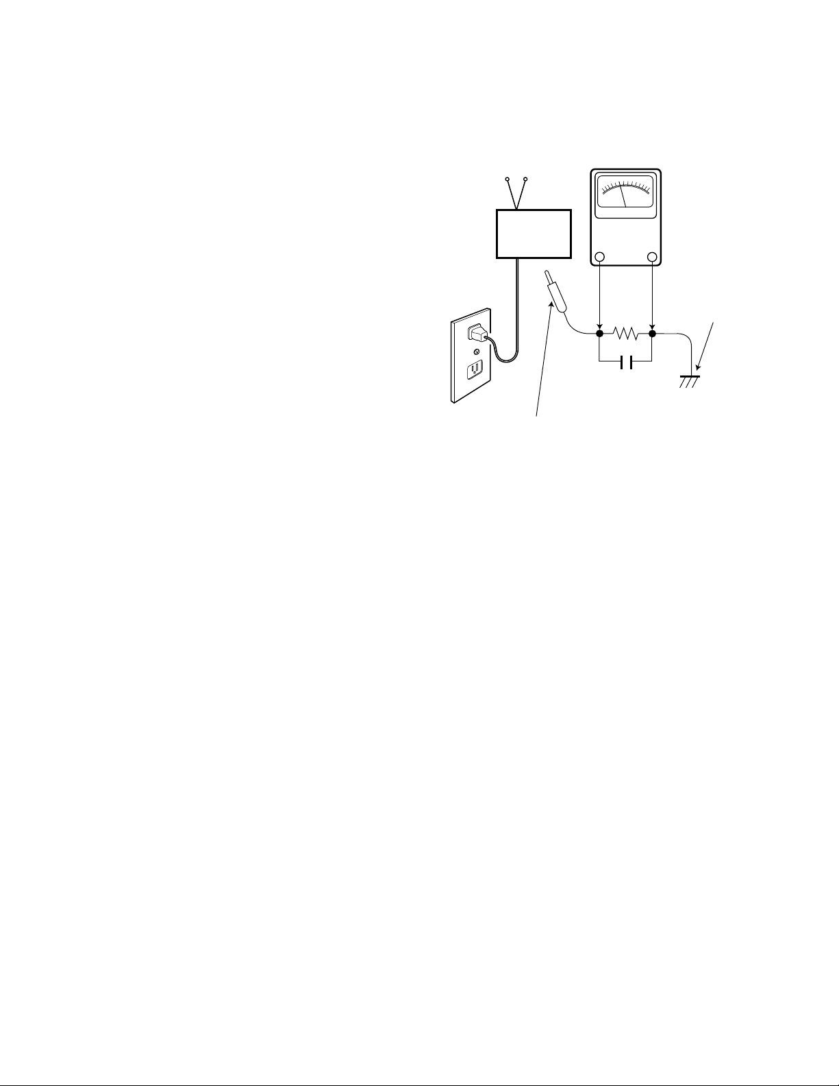
LEAKAGE CURRENT CHECK
Plug the AC line cord directly into a 120 VAC outlet. (Do not
use an isolation transformer for this check.) Use an AC voltmeter, that has 5000 ohms per volt or more sensitivity.
Connect a 1500 ohm 10 watt resistor, paralleled by a 0.15 µF
150 VAC capacitor, between a known good earth ground
(water pipe, conduit, etc.) and all exposed metal parts of the
cabinet (antennas, handle bracket, metal cabinet, screw
heads, metal overlays, control shafts, etc.). Measure the AC
voltage across the 1500 ohm resistor. The AC voltage
should not exceed 750 mV. A reading exceeding 750 mV
indicates that a dangerous potential exists. The fault must
be located and corrected. Repeat the above test with the
receiver power plug reversed.
NEVER RETURN A RECEIVER TO THE CUSTOMER
WITHOUT TAKING THE NECESSARY CORRECTIVE ACTION.
X-RADIATION PRECAUTION
The primary source of X-RADIATION in solid-state receivers is
the picture tube. The picture tube is specially constructed to
limit X-Ray emission. For continued X-RADIATION protection,
the replacement tube must be the same type as the original
(including the suffix letter in the part numbers). Excessive high
voltage may produce potentially hazardous X-RADIATION. To
avoid such hazards, the high voltage must be maintained within
specific limits. Refer to the X-RADIATION WARNING NOTE on
the CHASSIS SCHEMATIC in this service manual for specific
high voltage limits. If the high voltage exceeds specified limits,
check the components specified on the chassis schematic
diagram and take the necessary corrective action. Carefully
follow the instructions for the +B Voltage Check and the High
Voltage Check to maintain the high voltage within the specified
limits.
HIGH VOLTAGE HOLD-DOWN TEST
To prevent X-RADIATION from the picture tube due to
excessive high voltage, a HOLD-DOWN circuit is provided in
the high voltage circuit. Every time the receiver is serviced,
the high voltage HOLD-DOWN circuit must be tested for
proper operation. Refer to the HIGH VOLTAGE HOLDDOWN TEST in service adjustments.
PRODUCT SAFETY NOTICE
When replacing components in a receiver, always keep in
mind the necessary product safety precautions. Pay special
attention to the replacement of components marked with a
star (★) in the parts list and in the schematic diagrams. To
ensure safe product operation, it is necessary to replace
those components with the exact same PARTS.
SAFETY INSTRUCTIONS
READING SHOULD NOT EXCEED 750 mV.
AC VOLTMETER
(5000 ohms per volt or more sensitivity)
TELEVISION
RECEIVER
Good earth ground
such as a water pipe,
conduit, etc.
AC OUTLET
1500 ohm
10 watt
0.15 µF 150V AC
To be touched to all of exposed metal parts.
Voltmeter Hook-up for Leakage Current Check.
GENERAL
This set has an on-screen Service Menu system included in the CPU that allows remote operation for most of the service adjustments.
To enter the Service Menu, first disconnect the AC power cord. Then while pressing the MENU key on the front control panel, reconnect the AC power cord. The adjustments can now be made with the remote control or front control panel keys.
ON-SCREEN SERVICE MENU SYSTEM
1. Enter the Service Menu:
•While pressing the MENU key on the front control panel, reconnect the
AC power cord. The Service Menu Display will now appear. See Figure 1.
2. Service Adjustments:
•Press the ▲ or ▼ key to select the desired service menu item you
want to adjust. (See page 5 for On-screen Service Menu.)
•Use the + or – key or number keys to adjust the data.
The + or – keys will increase or decrease the data sequentially.
The number keys (0 ~ 7) toggle only their respective bits between
1 and 0 and are used to change the Sub-Address. For example to
change bit 5 press the number 5 key. See below.
3. Exit from the Service Menu:
•Press the MENU key to turn off the Service Menu display.
SERVICE ADJUSTMENTS
— 3 —
IC802 (EEPROM) REPLACEMENT
When IC802 (EEPROM) is replaced, IC801 (CPU) will automatically write the initial reference data into IC802 for basic TV operation.
However, the bus data should be checked and some bus data should be set up before attempting the service adjustments.
(See pages 5 – 7, Table 1, for detailed bus data information.)
INITIAL BUS DATA SETUP
Note: When IC802 (EEPROM) is replaced, change the following initial reference data for proper TV operation before
attempting service adjustments.
1. Disconnect the AC power cord (AC 120V line).
2. While pressing the MENU key, reconnect the AC power cord. The Service Menu display will now appear.
3. Select NO.3C SCO (Sub Color) with ▲ or ▼ key. Adjust the data with + or – key for 05.
4. Select NO.3D STI (Sub Tint) with ▲ or ▼ key. Adjust the data with + or – key for 11.
5. Select NO.3E SB (Sub Bright) with ▲ or ▼ key. Adjust the data with + or – key for 1A.
6. Select NO.51 VS (V Size) with ▲ or ▼ key. Adjust the data with + or – key for 21.
7. Select NO.54 BLK7SSL3 (Blk Str Dis / Blk Str Cha / S Slice Dn2 / S Slice Dn1) with ▲ or ▼ key. Adjust the data with number keys for A0.
8. Select NO.55 AFC7OSD5OM3BSG2CA1 (AFC G Up / AFC G Dn / OSD Level / OSD / OM Det) with ▲ or ▼ key. Adjust the
data with number keys for 84.
9. Select NO. 56 VSD7ASD6HP4 (V Sync Det / Auto Slice Dn / FBP Vth L / H Phase) with ▲ or ▼ key. Adjust the data with
number keys for 07.
10. Select NO. 5C VSC5 (V S Correction) with ▲ or ▼ key. Adjust the data with + or – key for B1.
11. Select NO. 5D VAGC6VL5 (V AGC / V Linearity) with ▲ or ▼ key. Adjust the data with number keys for 55.
12. Select NO. 68 S4G7STR6CRP3 (SIF4.5 Gain Dn / S Trap Fine LSB / Cr Ped Adj ) with ▲ or ▼ key. Adjust the data with
number keys for 8B.
13. Select NO. 69 CBCR7CBP3 (CbCr Pedestal On / CbCr Gain Up / Cb pedestal Fine Adj) with ▲ or ▼ key. Adjust the data
with number keys for CC.
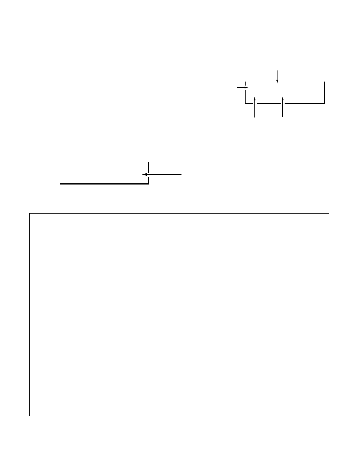
3C SCO
15 00010101
Figure 1. Service Menu Display
ITEM NO.
TITLE
BINARY DATA
(8 bit)
HEX DATA
(b7) (b6) (b5) (b4) (b3) (b2) (b1) (b0)
0 1 0 1 0 1 1 0
BINARY DATA
(8 bit)
 Loading...