

Page 1
DS19390
Model:
COLOR TELEVISION
AS
FILE NO.
G6VTM, PRODUCT CODE 111340680
REFERENCE No. SS510026-10
Notice
CORRECTION
SERVICE FLASH
PRODUCTION CHANGE
ADD INFORMATION
Please add this notice to the Service Manual listed below.
REVISION 10
Category:
U.S.A. / CANADA
Destination:
APRIL / 17 / 2001
Date:
19390-10
Effective from: Chassis No.
SS510026-08
REF: No.
NOTE: Match the Chassis No. on the unit’s back cover with the Chassis No. in the Service Manual.
If the Service Manual Chassis No. does not match the unit’s, additional Service Literature is
required. This chassis is similar to Chassis No. 19390-08. Only the Difference Service
Information is given in this manual. For detailed Service Information, refer to the Original Service
Manual and Notices for Chassis No. 19390-08 used in Model DS19390 (SS510026-08).
INITIAL BUS DATA SETUP
Note: When IC802 (EEPROM) is replaced, the Service Menu No. 003 HP (H Phase), No. 007 VLN (V Linearity), No. 010 VSC (V S-
Correction), No. 021 SBI (Sub-Bias), No. 023 POS (Pre/Over-Shoot), No. 028 PRE (Pre-Shoot Width), No. 037 AF (AutoFlesh),
No. 041 RYA (R-Y/B-Y Angle) and No. 055 STI (Sub-Tint) should be set up for proper TV operation before attempting the
service adjustments.
1. Disconnect the AC power cord (AC 120V line).
2. While pressing the MENU key, reconnect the AC power cord. The Service Menu display will now appear.
2a. Select No. 003 HP (H Phase) with ▲ or ▼ key. Adjust the data with + or – key for 9.
3. Select No. 007 VLN (V Linearity) with ▲ or ▼ key. Adjust the data with + or – key for 16.
4. Select No. 010 VSC (V S-Correction) with ▲ or ▼ key. Adjust the data with + or – key for 10.
5. Select No. 021 SBI (Sub-Bias) with ▲ or ▼ key. Adjust the data with + or – key for 60.
6. Select No. 023 POS (Pre/Over-Shoot) with ▲ or ▼ key. Adjust the data with + or – key for 1.
7. Select No. 028 PRE (Pre-Shoot Width) with ▲ or ▼ key. Adjust the data with + or – key for 3.
8. Select No. 037 AF (AutoFlesh) with ▲ or ▼ key. Adjust the data with + or – key for 1.
9. Select No. 041 RYA(R-Y/B-Y Angle) with ▲ or ▼ key. Adjust the data with + or – key for 2.
10. Select No. 055 STI (Sub-Tint) with ▲ or ▼ key. Adjust the data with + or – key for 20.
11. Press the MENU key to turn off the Service Menu display.
1. IN THE SERVICE ADJUSTMENTS LIST
PAGE 3
Page 2
1. IN THE SERVICE ADJUSTMENTS LIST (Continued)
PAGE 4
— 2 —
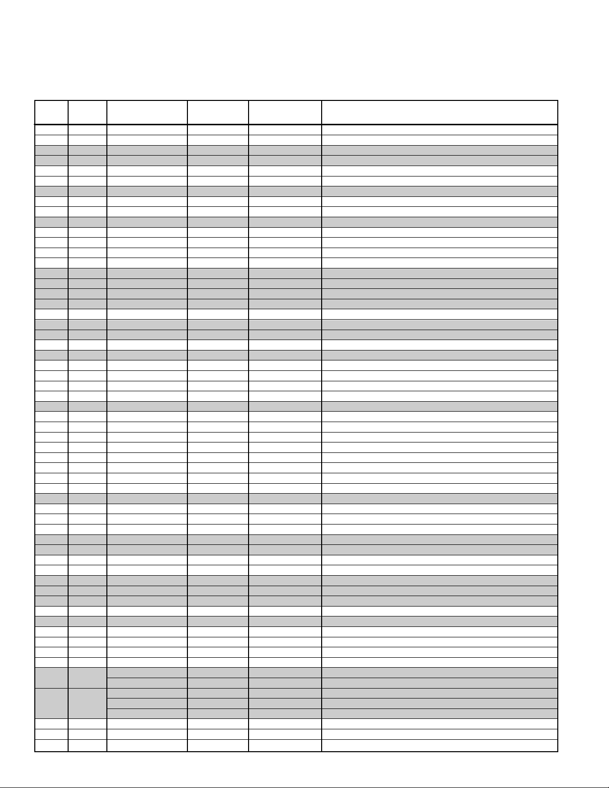
Table 1. ON-SCREEN SERVICE MENU
When IC802 (EEPROM) is replaced, check the bus data to confirm they are the same as below. The shaded menu should be checked
and be set up or readjusted according to the procedures described in the following pages. Initial Setup Data marked with an * should
be changed from Initial Reference Data. (See page 3 for Initial Bus Data Setup.)
No. TITLE
INITIAL REFERENCE INITIAL SETUP
RANGE OF DATA FUNCTION
DATA DATA
001 HFR 30 30 0~63 Align Horizontal Frequency
002 AFC 0 0 0, 1 Select Horizontal First Loop Gain & H-Sync Gating On/Off
003 HP 13 9* 0~31 Align Sync to Flyback Phase (Horizontal Phase)
004 VS 50 50 0~127 Align Vertical Amplitude (Vertical Size)
005 VPO 5 5 0~63 Align Vertical DC Bias (Vertical Position)
006 VSP 0 0 0, 1 Select Vertical Sync Separation Sensitivity
007 VLN 19 16* 0~31 Align Vertical Linearity
008 CRS 0 0 0~3 Service Test Mode (Normal/Black/White/Cross)
009 GRY 1 1 0, 1 OSD Gray Tone Enable
010 VSC 8 10* 0~31 Align Vertical S-Correction
011 HBR 3 3 0~7 H-Blanking Control for Right Side Edge on Screen
012 HBL 4 4 0~7 H-Blanking Control for Left Side Edge on Screen
013 CDM 0 0 0, 1 Select Count Down Mode
014 VC 7 7 0~7 Align Vertical Size Compensation
015 RB 0 0 0~255 Align Red OUT DC Level (Red Bias)
016 GB 0 0 0~255 Align Green OUT DC Level (Green Bias)
017 BB 0 0 0~255 Align Blue OUT DC Level (Blue Bias)
018 RD 64 64 0~127 Align Red OUT AC Level (Red Drive)
019 GD 8 8 0~15 Align Green OUT AC Level (Green Drive)
020 BD 64 64 0~127 Align Blue OUT AC Level (Blue Drive)
021 SBI 64 60* 0~127 Align Common RGB DC Level (Sub-Bias)
022 OSD 2 2 0~3 Align OSD AC Level
023 POS 0 1* 0, 1 Select Control for Pre/Over-Shoot Adjustment
024 FLS 1 1 0~7 Select Y/C Filter Mode
025 CKO 3 3 0~7 Select Color Killer Operational Point
026 GYA 0 0 0, 1 Select G-Y Angle
027 CRG 2 2 0~3 Select Coring Gain (w/Defeat)
028 PRE 1 3* 0~3 Select Pre-Shoot Width
029 WP 1 1 0~3 Select White Peak Limitter Operating Point
030 FSW 0 0 0, 1 Enable RGB Blanking or FBP
031 VBL 0 0 0, 1 Select Vertical Blanking Period
032 BSG 1 1 0~3 Select Black Stretch Gain
033 BSS 1 1 0~3 Select Black Stretch Start Point (w/Defeat)
034 DCR 1 1 0~3 Select Luma DC Restoration
035 YGM 1 1 0~3 Select Y Gamma Start Point
036 CBP 0 0 0, 1 Select Chroma BPF Bypass
037 AF 0 1* 0, 1 Enable AutoFlesh Function
038 BAT 4 4 0~7 Align Brightness ABL Threshold
039 MSD 0 0 0, 1 Disable Brightness Mid Stop
040 ABL 0 0 0, 1 Disable Brightness ABL
041 RYA 4 2* 0~15 R-Y/B-Y Angle
042 RAD 15 15 0~63 Align RF AGC Threshold (RF-AGC Delay)
043 IAS 0 0 0, 1 Disable IF and RF AGC (IF AGC Switch)
044 FMM 0 0 0, 1 Disable FM Outputs (FM Mute)
045 FL 15 15 0~31 Align WBA Output Level (FM Level)
046 VL 4 4 0~7 Align IF Video Level
053 SB 32 32 0~63 Align Sub-Brightness
054 SCO 10 10 0~31 Align Sub-Color
055 STI 22 20* 0~31 Align Sub-Tint
056 SSH 18 18 0~15 Align Sub-Sharpness
057 OPT 0 0 0~255 Option (Program Codes) (See Note 1 page 5.)
059 HR 13 13 0~31 Align OSD H-Position
062 SBO 5 5 0~255 Sub-Bright Offset
072 DRV
0~127 Red Drive Adjustment (See Note 2 page 5.)
0~127 Blue Drive Adjustment (See Note 2 page 5.)
– 0 0 0~255 Red Bias Adjustment (See Note 3 page 5.)
073 – 0 0 0~255 Green Bias Adjustment (See Note 3 page 5.)
– 0 0 0~255 Blue Bias Adjustment (See Note 3 page 5.)
074 R00 0 0 0~255 N/A
↓↓ ↓ ↓ ↓ ↓
146 R48 0 0 0~255 N/A
Page 3

Figure 1. Deflection Yoke Movement
Figure 2. Purity and Convergence Magnets
Figure 3. Adjusting Magnet
2. IN THE PURITY AND CONVERGENCE ADJUSTMENTS LIST
PAGE 8
— 3 —
PURITY ADJUSTMENT
1. When replacing picture tube or deflection yoke, mount
deflection yoke and purity-convergence magnets assembly
properly. See Figure 1. Position the picture tube facing east
or west. Demagnetize the picture tube and receiver using
an external degaussing coil. Set receiver to Service Menu
No. 073 (no vertical sweep) while degaussing.
2. Place the yoke on tube neck fully against glass.
2a.Place the CPM on the tube neck aligning the center of
the purity magnet tabs (2 pole) over center of Focus
Gap (G3 & G4). See Figure 2.
3. Connect a color bar generator to the antenna terminal.
Switch the generator to a white field. Move yoke backward
on the neck until a uniform white field is obtained.
4. Allow 30 minutes warm up on a blank white field (high intensity grayscale).
Note: If white field cannot be obtained, check Grayscale
Adjustments on page 6.
5. Set the picture controls to the Auto levels. Select a green
raster, either with the signal generator or by adjusting the
bias controls. If a signal generator is used for this step, Skip
to Step 10. If the bias controls will be used, go to step 6.
6. Adjust Service Menu No. 015 RB (R-Bias), No. 016 GB (GBias), and No. 017 BB (B-Bias) data to 0 each.
7. Select Service Menu No. 073 (no vertical sweep).
8. Adjust the screen control counterclockwise until the
horizontal scan lines is no longer visible.
9. Select Service Menu No. 016 GB (G-Bias) and raise the
data to produce green raster. If retrace lines appear,
reduce screen control slightly.
10.Pull yoke back on the tube neck to obtain three-color raster
(blue, green and red).
11. Adjust the angle between the two purity magnet tabs to
center the vertical green belt in the picture tube. Do not
rotate tabs. See Figure 3.
12.Slowly slide the deflection yoke forward until a uniform
green screen is obtained.
13.Check the purity of the red and blue screens for uniformity.
Turn off other colors to check (use bias controls) or use
generator. If necessary, readjust the yoke position until all
screens are pure.
14.If bias controls and screen control were used to set purity,
reset Grayscale and Brightness Level. Refer to Grayscale
Adjustment on page 6 and Brightness Level Adjustment on
page 7.
15.Confirm that the yoke is not tilted. Tighten the yoke
mounting screw. Adjust convergence next.
DEFLECTION YOKE
SIX-POLE
MAGNET TABS
DEFLECTION YOKE
MOUNTING SCREW
PURITY
MAGNET
TABS
FOUR-POLE
MAGNET TABS
4
3
1
2
ANGLE OF MAGNET TABS
ANGLE
OF TABS
FOCUS GAP
(G3-G4)
RUBBER
WEDGE
MAGNET TABS
Page 4
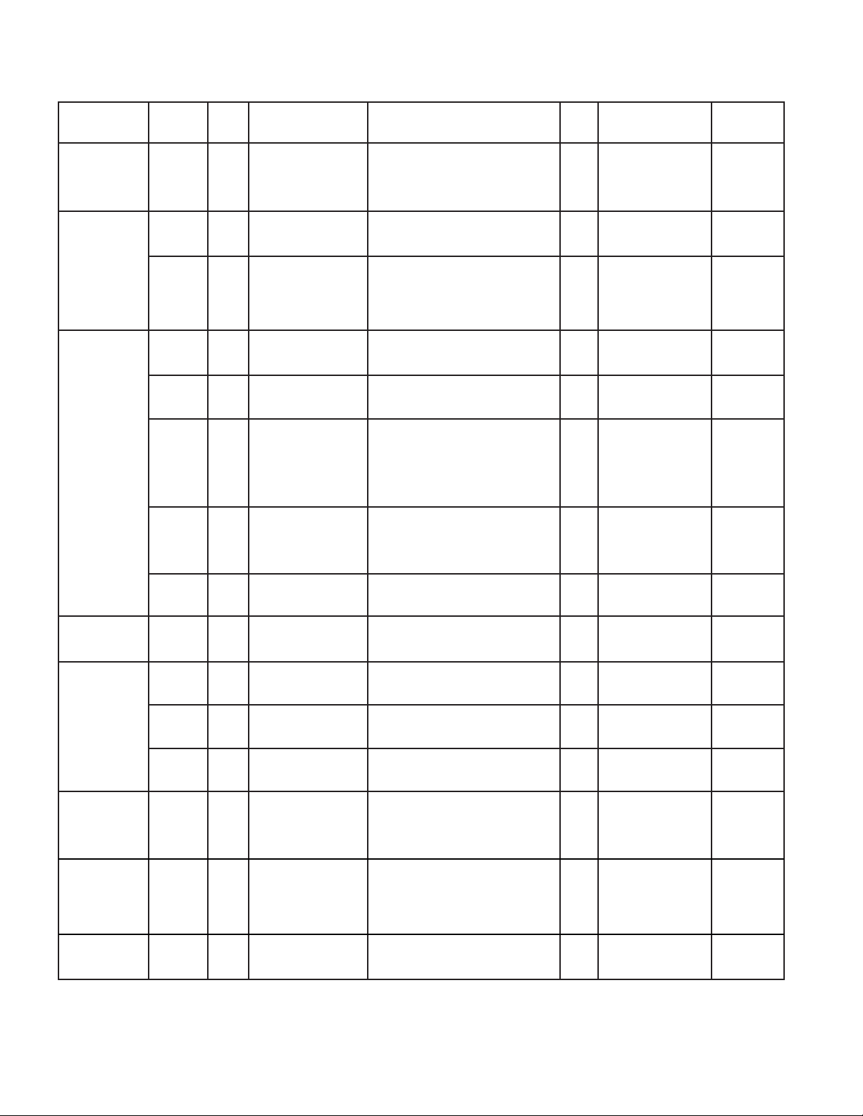
Page &
Section
Schematic
Location
Part No. Description Q’ty
Interchange-
ability
Old
403 353 4303 MT-POLYPRO 7100P H 1.5K
1NO
404 077 4303 MT-POLYPRO 7100P H 1.5K
★
C411 - - - - - - - - - - - - - - - - - - - - - - - - - - - - - - - - - - - - - - - - - - - - - - - - - - - - - - - - - - - - - - - - - - - - - - D
New
403 343 7901 MT-POLYPRO 7200P H 1.5K
1NO
404 077 4402 MT-POLYPRO 7200P H 1.5K
Old 645 044 9123 COIL, DEGAUSSING 1 NO
★
L901 - - - - - - - - - - - - - - - - - - - - - - - - - - - - - - - - - - - - - - - - - - - - - - - - - - - - - - - - - - - - - - - - - - - - - - D
New 645 044 9130 COIL, DEGAUSSING 1 NO
Old
610 238 2846 DEFLECTION YOKE
1NO
610 238 2853 DEFLECTION YOKE
★
L902 - - - - - - - - - - - - - - - - - - - - - - - - - - - - - - - - - - - - - - - - - - - - - - - - - - - - - - - - - - - - - - - - - - - - - - D
645 028 5943 YOKE, DEFLECTION
New 645 029 0893 YOKE, DEFLECTION 1 NO
645 042 7718 YOKE, DEFLECTION
Old 401 064 5701 OXIDE-MT 1.8 JA 2W 1 NO
★
R497 - - - - - - - - - - - - - - - - - - - - - - - - - - - - - - - - - - - - - - - - - - - - - - - - - - - - - - - - - - - - - - - - - - - - - - D
New 401 068 1600 OXIDE-MT 4.7 JA 2W 1 NO
Old 401 027 5007 CARBON 68 JA 1/6W 1 NO
R506 - - - - - - - - - - - - - - - - - - - - - - - - - - - - - - - - - - - - - - - - - - - - - - - - - - - - - - - - - - - - - - - - - - - - - - D
New 401 024 6700 CARBON 100 JA 1/6W 1 NO
402 055 3201 WIRE WOUND 1 KA WA 6W
Old 402 055 3300 WIRE WOUND 1 KA ZA 6W 1 NO
402 072 2706 WIRE WOUND 1 KA 5W
★
R601 - - - - - - - - - - - - - - - - - - - - - - - - - - - - - - - - - - - - - - - - - - - - - - - - - - - - - - - - - - - - - - - - - - - - - - D
402 057 8006 WIRE WOUND 3.3 KA ZA 6W
New 402 058 4403 WIRE WOUND 3.3 KA WA 6W 1 NO
402 075 4707 WIRE WOUND 3.3 KA 5W
Old
402 057 1304
WIRE WOUND 120 JA 15W
1NO
402 083 5208
WIRE WOUND 120 JA 15W
★R608
- - - - - - - - - - - - - - - - - - - - - - - - - - - - - - - - - - - - - - - - - - - - - - - - - - - - - - - - - - - - - - - - - - - - - - D
New
402 056 5204
WIRE WOUND 140 JA 15W
1NO
402 083 5307
WIRE WOUND 140 JA 15W
R714,
Old 401 255 9006 MT-GLAZE 82 JA1/10W 2 NO
R724
- - - - - - - - - - - - - - - - - - - - - - - - - - - - - - - - - - - - - - - - - - - - - - - - - - - - - - - - - - - - - - - - - - - - - - D
New NOT USED NO
R718,
Old NOT USED NO
R728
- - - - - - - - - - - - - - - - - - - - - - - - - - - - - - - - - - - - - - - - - - - - - - - - - - - - - - - - - - - - - - - - - - - - - - D
New 401 255 9006 MT-GLAZE 82 JA1/10W 2 NO
Old 610 289 2741 ASSY, PWB, MAIN 1 NO
A100 - - - - - - - - - - - - - - - - - - - - - - - - - - - - - - - - - - - - - - - - - - - - - - - - - - - - - - - - - - - - - - - - - - - - - - D
New 610 291 1671 ASSY, PWB, MAIN 1 NO
Old 610 289 2758 ASSY, PWB, SOCKET 1 NO
A700 - - - - - - - - - - - - - - - - - - - - - - - - - - - - - - - - - - - - - - - - - - - - - - - - - - - - - - - - - - - - - - - - - - - - - - D
New 610 291 1688 ASSY, PWB, SOCKET 1 NO
Old 645 025 6103 SOCKET, CRT 8P 1 NO
★
K701 - - - - - - - - - - - - - - - - - - - - - - - - - - - - - - - - - - - - - - - - - - - - - - - - - - - - - - - - - - - - - - - - - - - - - - D
New NOT USED NO
Old NOT USED NO
- - - - - - - - - - - - - - - - - - - - - - - - - - - - - - - - - - - - - - - - - - - - - - - - - - - - - - - - - - - - - - - - - - - - - - D
★K701A 645 026 1992 SOCKET, CRT 8P
New 645 036 4143 SOCKET, CRT 8P 1 NO
645 036 4150 SOCKET, CRT 8P
413 007 6201 CRT A48AAB37X
Old 413 007 7901 CRT A48AAB37X 1 NO
★Q901
414 009 2703 CRT A48AGD12X
- - - - - - - - - - - - - - - - - - - - - - - - - - - - - - - - - - - - - - - - - - - - - - - - - - - - - - - - - - - - - - - - - - - - - - D
New 414 009 8101 CRT A48JLL40X 1 NO
414 010 3003 CRT A48JLL40X(P)
Old NOT USED NO
Q901C - - - - - - - - - - - - - - - - - - - - - - - - - - - - - - - - - - - - - - - - - - - - - - - - - - - - - - - - - - - - - - - - - - - - - - D
New 610 217 7787 CG PURITY MAGNET 1 NO
Page 13,
Chassis
Electrical
Parts List
3. IN THE CHASSIS ELECTRICAL PARTS LIST
The reason for change.
A : Misprint B : Quality Reliability C : Standardization D : Design
E : Add as a possible sub F : Schematic location change G : Purchasing Request
Reason
Page 16,
Chassis
Electrical
Parts List
Page 17,
Chassis
Electrical
Parts List
Page 14,
Chassis
Electrical
Parts List
Printed in U.S.A.
April / 2001 / 2200 SMC
For parts or service contact
SANYO Fisher Service Corporation
21605 Plummer Street,
Chatsworth, CA 91311 (U.S.A.)
300 Applewood Crescent,
Concord, Ontario L4K 5C7 (CANADA)
Page 5

DS19390
Model:
COLOR TELEVISION
AS
FILE NO.
G6VSM, PRODUCT CODE 111340680
REFERENCE No. SS510026-09
Notice
CORRECTION
SERVICE FLASH
PRODUCTION CHANGE
ADD INFORMATION
Please add this notice to the Service Manual listed below.
REVISION 9
Category:
U.S.A. / CANADA
Destination:
APRIL / 17 / 2001
Date:
19390-09
Effective from: Chassis No.
SS510026-08
REF: No.
NOTE: Match the Chassis No. on the unit’s back cover with the Chassis No. in the Service Manual.
If the Service Manual Chassis No. does not match the unit’s, additional Service Literature is
required. This chassis is similar to Chassis No. 19390-08. Only the Difference Service
Information is given in this manual. For detailed Service Information, refer to the Original Service
Manual and Notices for Chassis No. 19390-08 used in Model DS19390 (SS510026-08).
INITIAL BUS DATA SETUP
Note: When IC802 (EEPROM) is replaced, the Service Menu No. 003 HP (H Phase), No. 007 VLN (V Linearity), No. 010 VSC (V S-
Correction), No. 021 SBI (Sub-Bias), No. 023 POS (Pre/Over-Shoot), No. 028 PRE (Pre-Shoot Width), No. 037 AF (AutoFlesh),
No. 041 RYA (R-Y/B-Y Angle) and No. 055 STI (Sub-Tint) should be set up for proper TV operation before attempting the
service adjustments.
1. Disconnect the AC power cord (AC 120V line).
2. While pressing the MENU key, reconnect the AC power cord. The Service Menu display will now appear.
2a. Select No. 003 HP (H Phase) with ▲ or ▼ key. Adjust the data with + or – key for 9.
3. Select No. 007 VLN (V Linearity) with ▲ or ▼ key. Adjust the data with + or – key for 16.
4. Select No. 010 VSC (V S-Correction) with ▲ or ▼ key. Adjust the data with + or – key for 10.
5. Select No. 021 SBI (Sub-Bias) with ▲ or ▼ key. Adjust the data with + or – key for 60.
6. Select No. 023 POS (Pre/Over-Shoot) with ▲ or ▼ key. Adjust the data with + or – key for 1.
7. Select No. 028 PRE (Pre-Shoot Width) with ▲ or ▼ key. Adjust the data with + or – key for 3.
8. Select No. 037 AF (AutoFlesh) with ▲ or ▼ key. Adjust the data with + or – key for 1.
9. Select No. 041 RYA(R-Y/B-Y Angle) with ▲ or ▼ key. Adjust the data with + or – key for 2.
10. Select No. 055 STI (Sub-Tint) with ▲ or ▼ key. Adjust the data with + or – key for 20.
11. Press the MENU key to turn off the Service Menu display.
1. IN THE SERVICE ADJUSTMENTS LIST
PAGE 3
Page 6
1. IN THE SERVICE ADJUSTMENTS LIST (Continued)
PAGE 4
— 2 —
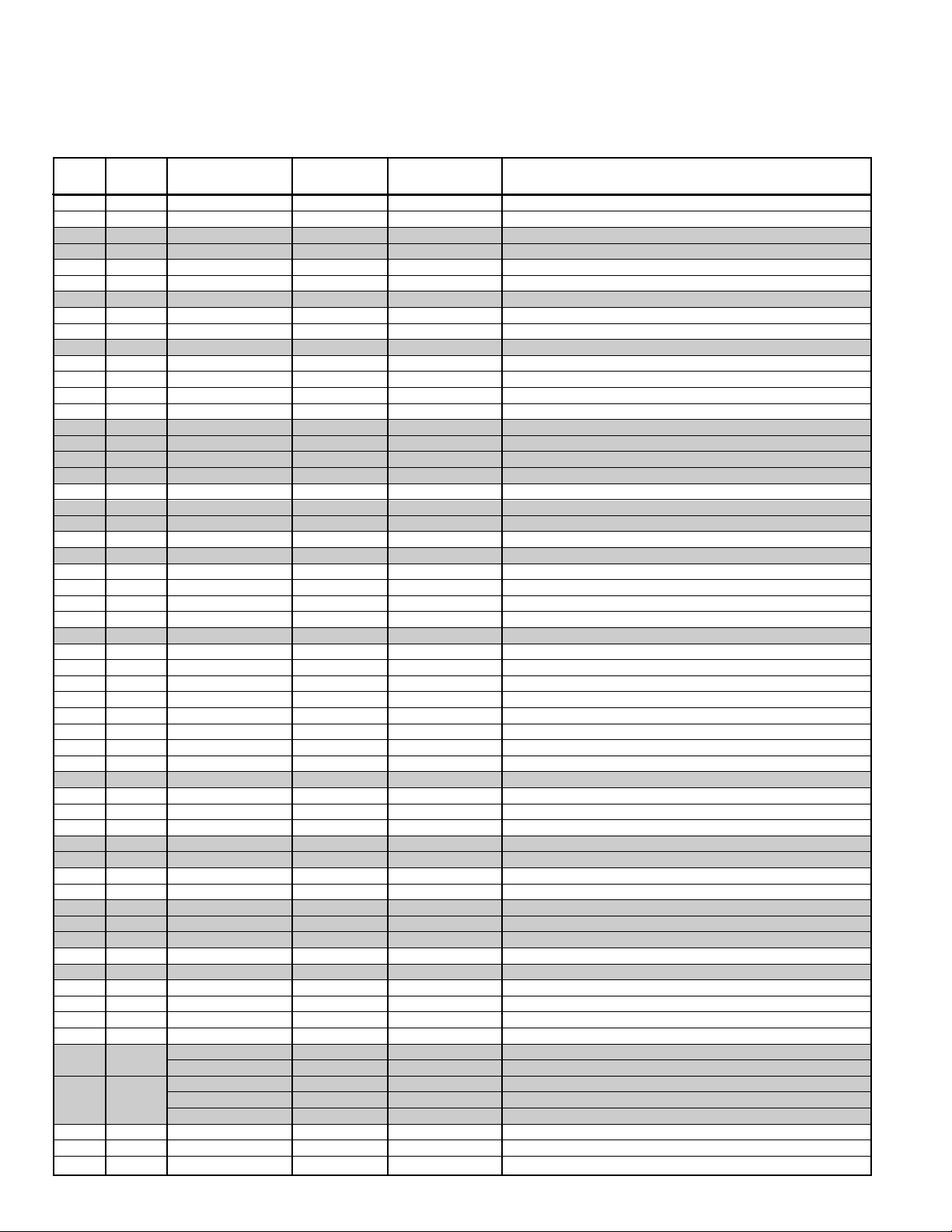
Table 1. ON-SCREEN SERVICE MENU
When IC802 (EEPROM) is replaced, check the bus data to confirm they are the same as below. The shaded menu should be checked
and be set up or readjusted according to the procedures described in the following pages. Initial Setup Data marked with an * should
be changed from Initial Reference Data. (See page 3 for Initial Bus Data Setup.)
No. TITLE
INITIAL REFERENCE INITIAL SETUP
RANGE OF DATA FUNCTION
DATA DATA
001 HFR 30 30 0~63 Align Horizontal Frequency
002 AFC 0 0 0, 1 Select Horizontal First Loop Gain & H-Sync Gating On/Off
003 HP 13 9* 0~31 Align Sync to Flyback Phase (Horizontal Phase)
004 VS 50 50 0~127 Align Vertical Amplitude (Vertical Size)
005 VPO 5 5 0~63 Align Vertical DC Bias (Vertical Position)
006 VSP 0 0 0, 1 Select Vertical Sync Separation Sensitivity
007 VLN 19 16* 0~31 Align Vertical Linearity
008 CRS 0 0 0~3 Service Test Mode (Normal/Black/White/Cross)
009 GRY 1 1 0, 1 OSD Gray Tone Enable
010 VSC 8 10* 0~31 Align Vertical S-Correction
011 HBR 3 3 0~7 H-Blanking Control for Right Side Edge on Screen
012 HBL 4 4 0~7 H-Blanking Control for Left Side Edge on Screen
013 CDM 0 0 0, 1 Select Count Down Mode
014 VC 7 7 0~7 Align Vertical Size Compensation
015 RB 0 0 0~255 Align Red OUT DC Level (Red Bias)
016 GB 0 0 0~255 Align Green OUT DC Level (Green Bias)
017 BB 0 0 0~255 Align Blue OUT DC Level (Blue Bias)
018 RD 64 64 0~127 Align Red OUT AC Level (Red Drive)
019 GD 8 8 0~15 Align Green OUT AC Level (Green Drive)
020 BD 64 64 0~127 Align Blue OUT AC Level (Blue Drive)
021 SBI 64 60* 0~127 Align Common RGB DC Level (Sub-Bias)
022 OSD 2 2 0~3 Align OSD AC Level
023 POS 0 1* 0, 1 Select Control for Pre/Over-Shoot Adjustment
024 FLS 1 1 0~7 Select Y/C Filter Mode
025 CKO 3 3 0~7 Select Color Killer Operational Point
026 GYA 0 0 0, 1 Select G-Y Angle
027 CRG 2 2 0~3 Select Coring Gain (w/Defeat)
028 PRE 1 3* 0~3 Select Pre-Shoot Width
029 WP 1 1 0~3 Select White Peak Limitter Operating Point
030 FSW 0 0 0, 1 Enable RGB Blanking or FBP
031 VBL 0 0 0, 1 Select Vertical Blanking Period
032 BSG 1 1 0~3 Select Black Stretch Gain
033 BSS 1 1 0~3 Select Black Stretch Start Point (w/Defeat)
034 DCR 1 1 0~3 Select Luma DC Restoration
035 YGM 1 1 0~3 Select Y Gamma Start Point
036 CBP 0 0 0, 1 Select Chroma BPF Bypass
037 AF 0 1* 0, 1 Enable AutoFlesh Function
038 BAT 4 4 0~7 Align Brightness ABL Threshold
039 MSD 0 0 0, 1 Disable Brightness Mid Stop
040 ABL 0 0 0, 1 Disable Brightness ABL
041 RYA 4 2* 0~15 R-Y/B-Y Angle
042 RAD 15 15 0~63 Align RF AGC Threshold (RF-AGC Delay)
043 IAS 0 0 0, 1 Disable IF and RF AGC (IF AGC Switch)
044 FMM 0 0 0, 1 Disable FM Outputs (FM Mute)
045 FL 15 15 0~31 Align WBA Output Level (FM Level)
046 VL 4 4 0~7 Align IF Video Level
053 SB 32 32 0~63 Align Sub-Brightness
054 SCO 10 10 0~31 Align Sub-Color
055 STI 22 20* 0~31 Align Sub-Tint
056 SSH 18 18 0~15 Align Sub-Sharpness
057 OPT 0 0 0~255 Option (Program Codes) (See Note 1 page 5.)
059 HR 13 13 0~31 Align OSD H-Position
062 SBO 5 5 0~255 Sub-Bright Offset
072 DRV
0~127 Red Drive Adjustment (See Note 2 page 5.)
0~127 Blue Drive Adjustment (See Note 2 page 5.)
– 0 0 0~255 Red Bias Adjustment (See Note 3 page 5.)
073 – 0 0 0~255 Green Bias Adjustment (See Note 3 page 5.)
– 0 0 0~255 Blue Bias Adjustment (See Note 3 page 5.)
074 R00 0 0 0~255 N/A
↓↓ ↓ ↓ ↓ ↓
146 R48 0 0 0~255 N/A
Page 7
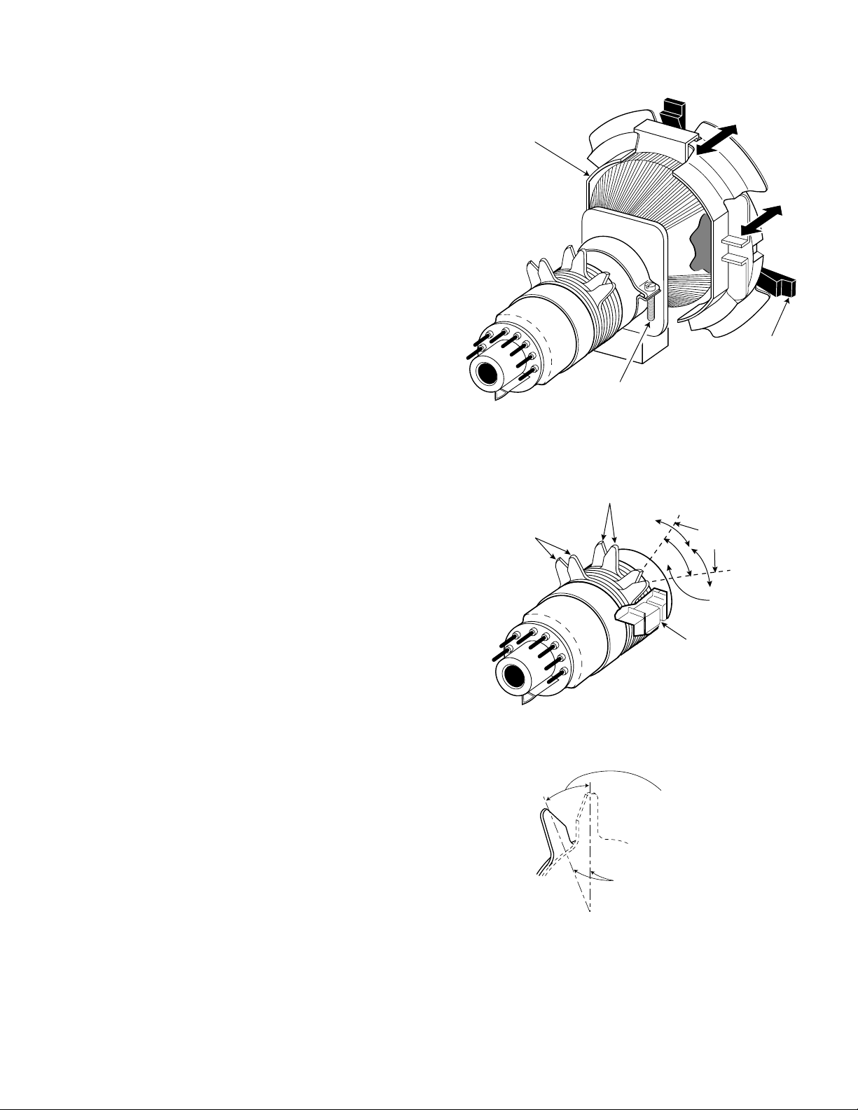
Figure 1. Deflection Yoke Movement
Figure 2. Purity and Convergence Magnets
Figure 3. Adjusting Magnet
2. IN THE PURITY AND CONVERGENCE ADJUSTMENTS LIST
PAGE 8
— 3 —
PURITY ADJUSTMENT
1. When replacing picture tube or deflection yoke, mount
deflection yoke and purity-convergence magnets assembly
properly. See Figure 1. Position the picture tube facing east
or west. Demagnetize the picture tube and receiver using
an external degaussing coil. Set receiver to Service Menu
No. 073 (no vertical sweep) while degaussing.
2. Place the yoke on tube neck fully against glass.
2a.Place the CPM on the tube neck aligning the center of
the purity magnet tabs (2 pole) over center of Focus
Gap (G3 & G4). See Figure 2.
3. Connect a color bar generator to the antenna terminal.
Switch the generator to a white field. Move yoke backward
on the neck until a uniform white field is obtained.
4. Allow 30 minutes warm up on a blank white field (high intensity grayscale).
Note: If white field cannot be obtained, check Grayscale
Adjustments on page 6.
5. Set the picture controls to the Auto levels. Select a green
raster, either with the signal generator or by adjusting the
bias controls. If a signal generator is used for this step, Skip
to Step 10. If the bias controls will be used, go to step 6.
6. Adjust Service Menu No. 015 RB (R-Bias), No. 016 GB (GBias), and No. 017 BB (B-Bias) data to 0 each.
7. Select Service Menu No. 073 (no vertical sweep).
8. Adjust the screen control counterclockwise until the
horizontal scan lines is no longer visible.
9. Select Service Menu No. 016 GB (G-Bias) and raise the
data to produce green raster. If retrace lines appear,
reduce screen control slightly.
10.Pull yoke back on the tube neck to obtain three-color raster
(blue, green and red).
11. Adjust the angle between the two purity magnet tabs to
center the vertical green belt in the picture tube. Do not
rotate tabs. See Figure 3.
12.Slowly slide the deflection yoke forward until a uniform
green screen is obtained.
13.Check the purity of the red and blue screens for uniformity.
Turn off other colors to check (use bias controls) or use
generator. If necessary, readjust the yoke position until all
screens are pure.
14.If bias controls and screen control were used to set purity,
reset Grayscale and Brightness Level. Refer to Grayscale
Adjustment on page 6 and Brightness Level Adjustment on
page 7.
15.Confirm that the yoke is not tilted. Tighten the yoke
mounting screw. Adjust convergence next.
DEFLECTION YOKE
SIX-POLE
MAGNET TABS
DEFLECTION YOKE
MOUNTING SCREW
PURITY
MAGNET
TABS
FOUR-POLE
MAGNET TABS
4
3
1
2
ANGLE OF MAGNET TABS
ANGLE
OF TABS
FOCUS GAP
(G3-G4)
RUBBER
WEDGE
MAGNET TABS
Page 8

Printed in U.S.A.
Page &
Section
Schematic
Location
Part No.
Description
Q’ty
Interchange-
ability
Old
403 353 4303 MT-POLYPRO 7100P H 1.5K
1NO
404 077 4303 MT-POLYPRO 7100P H 1.5K
★
C411 - - - - - - - - - - - - - - - - - - - - - - - - - - - - - - - - - - - - - - - - - - - - - - - - - - - - - - - - - - - - - - - - - - - - - - D
New
403 343 8304 MT-POLYPRO 8000P H 1.5K
1NO
404 077 4709 MT-POLYPRO 8000P H 1.5K
Old
403 346 7304 MT-POLYPRO 0.36U J 250V
1NO
404 081 2906 MT-POLYPRO 0.36U M 200V
★C417
- - - - - - - - - - - - - - - - - - - - - - - - - - - - - - - - - - - - - - - - - - - - - - - - - - - - - - - - - - - - - - - - - - - - - - D
New
403 346 7007 MT-POLYPRO 0.24U J 250V
1NO
404 081 2500 MT-POLYPRO 0.24U M 200V
Old
610 238 2846 DEFLECTION YOKE
1NO
610 238 2853 DEFLECTION YOKE
★
L902 - - - - - - - - - - - - - - - - - - - - - - - - - - - - - - - - - - - - - - - - - - - - - - - - - - - - - - - - - - - - - - - - - - - - - - D
New 645 026 3927 YOKE, DEFLECTION 1 NO
Old 401 064 9907 OXIDE-MT 10K JA 2W 1 NO
★
R407 - - - - - - - - - - - - - - - - - - - - - - - - - - - - - - - - - - - - - - - - - - - - - - - - - - - - - - - - - - - - - - - - - - - - - - D
New 401 069 8202 OXIDE-MT 8.2K JA 2W 1 NO
Old 401 064 5701 OXIDE-MT 1.8 JA 2W 1 NO
★
R497 - - - - - - - - - - - - - - - - - - - - - - - - - - - - - - - - - - - - - - - - - - - - - - - - - - - - - - - - - - - - - - - - - - - - - - D
New 401 066 3002 OXIDE-MT 2.2 JA 2W 1 NO
402 055 3201 WIRE WOUND 1 KA WA 6W
Old 402 055 3300 WIRE WOUND 1 KA ZA 6W 1 NO
402 072 2706 WIRE WOUND 1 KA 5W
★
R601 - - - - - - - - - - - - - - - - - - - - - - - - - - - - - - - - - - - - - - - - - - - - - - - - - - - - - - - - - - - - - - - - - - - - - - D
402 057 8006 WIRE WOUND 3.3 KA ZA 6W
New 402 058 4403 WIRE WOUND 3.3 KA WA 6W 1 NO
402 075 4707 WIRE WOUND 3.3 KA 5W
Old
402 057 1304
WIRE WOUND 120 JA 15W
1NO
402 083 5208
WIRE WOUND 120 JA 15W
★R608
- - - - - - - - - - - - - - - - - - - - - - - - - - - - - - - - - - - - - - - - - - - - - - - - - - - - - - - - - - - - - - - - - - - - - - D
New
402 056 5204
WIRE WOUND 140 JA 15W
1NO
402 083 5307
WIRE WOUND 140 JA 15W
Old 610 289 2741 ASSY, PWB, MAIN 1 NO
A100 - - - - - - - - - - - - - - - - - - - - - - - - - - - - - - - - - - - - - - - - - - - - - - - - - - - - - - - - - - - - - - - - - - - - - - D
New 610 291 4948 ASSY, PWB, MAIN NO
Old 610 289 2758 ASSY, PWB, SOCKET 1 YES
A700 - - - - - - - - - - - - - - - - - - - - - - - - - - - - - - - - - - - - - - - - - - - - - - - - - - - - - - - - - - - - - - - - - - - - - - D
New
610 289 2758 ASSY, PWB, SOCKET
1 YES
610 291 4955
ASSY, PWB, SOCKET
413 007 6201 CRT A48AAB37X
Old 413 007 7901 CRT A48AAB37X 1 NO
414 009 2703 CRT A48AGD12X
★
Q901 - - - - - - - - - - - - - - - - - - - - - - - - - - - - - - - - - - - - - - - - - - - - - - - - - - - - - - - - - - - - - - - - - - - - - - D
New 414 009 3205 CRT A48KRD82X(DT) 1 NO
Old NOT USED NO
Q901C - - - - - - - - - - - - - - - - - - - - - - - - - - - - - - - - - - - - - - - - - - - - - - - - - - - - - - - - - - - - - - - - - - - - - - D
New 610 217 7794 CG PURITY MAGNET 1 NO
Page 13,
Chassis
Electrical
Parts List
3. IN THE CHASSIS ELECTRICAL PARTS LIST
The reason for change.
A : Misprint B : Quality Reliability C : Standardization
D : Design E : Add as a possible sub F : Schematic location change
G : Purchasing Request
Reason
Page 15,
Chassis
Electrical
Parts List
Page 17,
Chassis
Electrical
Parts List
Page 14,
Chassis
Electrical
Parts List
April / 2001 / 2200 SMC
For parts or service contact
SANYO Fisher Service Corporation
21605 Plummer Street,
Chatsworth, CA 91311 (U.S.A.)
300 Applewood Crescent,
Concord, Ontario L4K 5C7 (CANADA)
Page 16,
Chassis
Electrical
Parts List
Page 9

AS
FILE NO.
SERVICE MANUAL
(SUPPLEMENT)
Remote Control Color
Television
DS19390 (U.S.A.)
(CANADA)
VERSION ADVANCE
Chassis No. 19390-08
NOTE: Match the Chassis No. on
the unit’s back cover with
the Chassis No. in the
Service Manual.
If the Original Version
Service Manual Chassis
No. does not match the
unit’s, additional Service
Literature is required. You
must refer to “Notices” to
the Original Service Manual
prior to servicing the unit.
G6VRM, PRODUCT CODE 111340680
REFERENCE No. SS510026-08
THIS CHASSIS IS SIMILAR TO MODEL AVM-1909S, CHASSIS NUMBER
G6V-1901S0. SERVICE INFORMATION GIVEN IN THIS MANUAL IS ONLY
THE DIFFERENCE INFORMATION FROM MODEL AVM-1901S, CHASSIS
NUMBER G6V-1901S0.
FOR ADDITIONAL SERVICE INFORMATION, REFER TO THE SERVICE
MANUAL FOR CHASSIS NUMBER G6V-1901S0 USED IN MODEL
AVM-1901S (SM5110190).
A
S
Page 10

1 610 292 4701 CABINET FRONT 610 291 2166 CABINET FRONT
610 289 2888 OWNER’S MANUAL 610 292 9164 OWNER’S MANUAL
DIFFERENCES
MODEL DS19390 (Chassis No. 19390-08) SAME AS MODEL AVM-1901S
(Chassis No. G6V-1901S0) EXCEPT
:
1. IN THE CABINET / ACCESSORY PARTS LIST (PAGE 18)
MODEL AVM-1901S (Chassis No. G6V-1901S0)
MODEL DS19390 (Chassis No. 19390-08)
Part No. Description
KEY NO.
Part No. Description
A
S
7, 8
7, 8
7
6
7
2
1
3
5
4
Printed in U.S.A.
April / 2001 / 2200 SMC
For parts or service contact
SANYO Fisher Service Corporation
21605 Plummer Street,
Chatsworth, CA 91311 (U.S.A.)
300 Applewood Crescent,
Concord, Ontario L4K 5C7 (CANADA)
Page 11

DS19390
Model:
COLOR TELEVISION
AS
FILE NO.
G6VKM, PRODUCT CODE 111340680
REFERENCE No. SS510026-07
Notice
CORRECTION
SERVICE FLASH
PRODUCTION CHANGE
ADD INFORMATION
Please add this notice to the Service Manual listed below.
REVISION 7
Category:
U.S.A.
Destination:
JUNE / 5 / 2000
Date:
19390-07
Effective from: Chassis No.
SS510026-05
REF: No.
NOTE: Match the Chassis No. on the unit’s back cover with the Chassis No. in the Ser vice Manual.
If the Service Manual Chassis No. does not match the unit’s, additional Service Literature is
required. This chassis is similar to Chassis No. 19390-05. Only the Difference Service
Information is given in this manual.For detailed Service Information, ref er to the Original Service
Manual and Notices for Chassis No.19390-05 used in Model DS19390 (SS510026-05).
INITIAL BUS DATA SETUP
Note: When IC802 (EEPROM) is replaced, the Ser vice Menu No. 001 HP (H Phase), No. 013 TDS (Trap & D SW), No. 024 AG
(AFC Gain), No.026 SCO (Sub-Color), No.027 STI (Sub-Tint), and No. 031 HR (OSD Display H-Position) should be set up for
proper TV operation before attempting the service adjustments.
1. Disconnect the AC power cord (AC 120V line).
2. While pressing the MENU key, reconnect the AC power cord.The Service Menu display will now appear.
3. Select No. 001 HP (H Phase) with ▲ or ▼ key. Adjust the data with + or – key for 14.
4. Select No. 013 TDS (Trap & D SW) with ▲ or ▼ key. Adjust the data with + or – key for 1.
5. Select No. 024 AG (AFC Gain), with ▲ or ▼ key. Adjust the data with + or – key for 0.
6. Select No. 026 SCO (Sub Color) with ▲ or ▼ key. Adjust the data with + or – key for 7.
7. Select No. 027 STI (Sub Tint) with ▲ or ▼ key. Adjust the data with + or – key for 20.
8. Select No. 031 HR (OSD Display H-Position) with ▲ or ▼ key. Adjust the data with + or – key for 28.
9. Press the MENU key to turn off the Service Menu display.
1. IN THE SERVICE ADJUSTMENTS LIST
PAGE 3
Page 12

1. IN THE SERVICE ADJUSTMENTS LIST (Continued)
PAGE 4
Table 1. ON-SCREEN SERVICE MENU
When IC802 (EEPROM) is replaced, check the bus data to confirm they are the same as belo w.The shaded menu should be checked
and be set up or readjusted according to the procedures described in the following pages.Initial Setup Data marked with an * should
be changed from Initial Reference Data. (See page 3 for Initial Bus Data Setup.)
No. TITLE
INITIAL REFERENCE INITIAL SETUP
RANGE OF DAT A FUNCTION
DATA DATA
001 HP 15 14* 0~31 Horizontal Phase (Horizontal Centering)
002 IAS 0 0 0, 1 IF AGC Switch 0: TV (Normal) 1: AV (IF Gain Minimum)
003 RAD 25 25 0~63 RF AGC Delay
004 PT 64 64 0~127 PLL Tuning
005 ADA 31 31 0~63 APC Detect Adjust
006 CD 0 0 0, 1 C-Diff
007 VS 32 32 0~63 Vertical Size
008 RB 0 0 0~255 Red Bias
009 GB 0 0 0~255 Green Bias
010 BB 0 0 0~255 Blue Bias
011 RD 60 60 0~127 Red Drive
012 BD 60 60 0~127 Blue Drive
013 TDS 0 1* 0, 1 Trap & D (B.P.F.) Switch 0: OFF 1: ON
014 AF 0 0 0, 1 Auto Flesh 0: OFF 1: ON
015 BS 0 0 0, 1 Black Stretch 1: OFF 0: ON
016 VL 4 4 0~7 Video Level
017 FL 15 15 0~31 FM Level
018 NIS 1 1 0, 1 N/I Switch (Black Noise Inverter) 1: OFF 0: ON
019 ABL 1 1 0,1 ABL Defeat 0: OFF 1: ON
020 WP 1 1 0,1 White Peak Limiter 1: OFF 0: ON
021 GD 7 7 0~15 Green Drive Reduction
022 VC 0 0 0~7 Ver t. Comp
023 VD 32 32 0~63 Vert.DC
024 AG 3 0* 0~3 AFC Gain 00: Auto 01: High Gain 10: Low Gain 11: Non-Gate
025 SB 32 32 0~63 Sub-Brightness
026 SCO 10 7* 0~31 Sub-Color
027 STI 14 20* 0~31 Sub-Tint
028 SSH 8 8 0~15 Sub-Shar pness
029 OPT 0 0 0~255 Option 1 (
See Note 1 page 5.
)
030 OP2 0 0 0~255 Option 2 (
See Note 2 page 5.
)
031 HR 24 28* 0~63 H-Position (OSD H-Position)
032 INP N/A N/A N/A N/A
033 STE N/A N/A N/A N/A
034 FIL N/A N/A N/A N/A
035 LSP N/A N/A N/A N/A
036 HSP N/A N/A N/A N/A
037 SPV N/A N/A N/A N/A
038 PCO N/A N/A N/A N/A
039 PTI N/A N/A N/A N/A
040 SBO 0 0 0~255 Sub Bright Offset
041 DRV
0~127 Red drive Adjustment (
See Note 3 page 5.
)
0~127 Blue Drive Adjustment (
See Note 3 page 5.
)
– 0 0 0~255 Red Bias Adjustment (
See Note 4 page 5.
)
042 – 0 0 0~255 Green Bias Adjustment (
See Note 4 page 5.
)
– 0 0 0~255 Blue Bias Adjustment (
See Note 4 page 5.
)
043 T00 0 0 0~255 N/A
↓↓ ↓ ↓ ↓ ↓
115 T48 0 0 0~255 N/A
1. IN THE SERVICE ADJUSTMENTS LIST (Continued)
PAGE 6
VERTICAL CENTERING ADJUSTMENT
1. Tune receiver to an active channel.
2. Ch eck that picture is in the ver tical center of TV screen. If picture center is too low, connect resistor R513 (470 ohm, 1W). If picture
center is too high, connect resistor R512 (470 ohm, 1W).
— 2 —
Page 13

PURITY ADJUSTMENT
1. When replacing picture tube or deflection yoke, mount
deflection yoke and purity-convergence magnets assembly
properly. See Figure 1. Position the picture tube facing east
or west. Demagnetize the picture tube and receiver using
an external degaussing coil. Set receiver to Service Menu
No.042 (no vertical sweep) while degaussing.
2. Place the yoke on tube neck fully against glass.
2A.Place the CPM on the tube neck aligning the center of
the purity magnet tabs (2 pole) over center of Focus
Gap (G3 & G4). See Figure 2.
3. Connect a color bar generator to the antenna terminal.
Switch the generator to a white field. Move yoke backward
on the neck until a uniform white field is obtained.
4. Allow 30 minutes w arm up on a blank white field (high intensity grayscale).
Note: If white field cannot be obtained, check Grayscale
Adjustments on page 6.
5. Set the picture controls to the Auto levels. Select a green
raster, either with the signal generator or by adjusting the
bias controls. If a signal generator is used for this step, Skip
to Step 10. If the bias controls will be used, go to step 6.
6. Adjust Service Menu No.008 RB (R-Bias), No. 009 GB (GBias), and No.010 BB (B-Bias) data to 0 each.
7. Select Service Menu No.042 (no vertical sweep).
8. Adjust the screen control counterclockwise until the
horizontal scan lines is no longer visible.
9. Select Service Menu No. 009 GB (G-Bias) and raise the
data to produce green raster. If retrace lines appear, reduce
screen control slightly.
10. Pull yoke back on the tube neck to obtain three-color raster
(blue, green and red).
11. Adjust the angle between the two purity magnet tabs to
center the vertical green belt in the picture tube. Do not
rotate tabs. See Figure 3.
12. Slowly slide the deflection yoke forward until a uniform
green screen is obtained.
13. Check the purity of the red and blue screens for uniformity.
Turn off other colors to check (use bias controls) or use
generator. If necessary, readjust the yoke position until all
screens are pure.
14. If bias controls and screen control were used to set purity,
reset Grayscale and Brightness Level. Refer to Grayscale
Adjustment on page 6 and Brightness Level Adjustment on
page 7.
15. Confirm that the yoke is not tilted. Tighten the yoke
mounting screw. Adjust convergence next.
RUBBER
WEDGE
DEFLECTION YOKE
DEFLECTION YOKE
MOUNTING SCREW
Figure 1. Deflection Yoke Movement
SIX-POLE
MAGNET TABS
FOUR-POLE
MAGNET TABS
ANGLE
OF TABS
PURITY
MAGNET
TABS
4
3
2
1
FOCUS GAP
(G3-G4)
Figure 2. Purity and Convergence Magnets
MAGNET TABS
ANGLE OF MAGNET TABS
Figure 3. Adjusting Magnet
2. IN THE PURITY AND CONVERGENCE ADJUSTMENTS LIST
PAGE 10
— 3 —
Page 14

Page &
Section
Schematic
Location
Part No.
Description
Q’ty
Interchange-
ability
Old
403 353 4303 MT-POLYPRO 7100P H 1.5K
1NO
404 077 4303 MT-POLYPRO 7100P H 1.5K
★
C411 - - - - - - - - - - - - - - - - - - - - - - - - - - - - - - - - - - - - - - - - - - - - - - - - - - - - - - - - - - - - - - D
New
403 343 7901 MT-POLYPRO 7200P H 1.5K
1NO
404 077 4402 MT-POLYPRO 7200P H 1.5K
645 002 9103
COIL, DEGAUSSING
Old
645 022 8582
COIL, DEGAUSSING 1 NO
645 027 9379 ASSY, COIL, DEGAUSSING
★
L901 - - - - - - - - - - - - - - - - - - - - - - - - - - - - - - - - - - - - - - - - - - - - - - - - - - - - - - - - - - - - - - D
New 645 031 6975 COIL, DEGAUSSING 1 NO
645 035 8814 ASSY, COIL, DEGAUSSING
Old
610 238 2846 DEFLECTION YOKE
1NO
610 238 2853 DEFLECTION YOKE
★
L902 - - - - - - - - - - - - - - - - - - - - - - - - - - - - - - - - - - - - - - - - - - - - - - - - - - - - - - - - - - - - - - D
New 645 028 5943 YOKE, DEFLECTION 1 NO
645 029 0893 YOKE, DEFLECTION
Old 401 286 5305 MT-FILM 2.4K FA 1/6W 1 NO
★
R421 - - - - - - - - - - - - - - - - - - - - - - - - - - - - - - - - - - - - - - - - - - - - - - - - - - - - - - - - - - - - - - D
New 401 053 0403 MT-FILM 2K FA 1/6W 1 NO
Old 401 064 5701 OXIDE-MT 1.8 JA 2W 1 NO
★
R497 - - - - - - - - - - - - - - - - - - - - - - - - - - - - - - - - - - - - - - - - - - - - - - - - - - - - - - - - - - - - - - D
New 401 068 1600 OXIDE-MT 4.7 JA 2W 1 NO
Old 401 027 5007 CARBON 68 JA 1/6W 1 NO
R506 - - - - - - - - - - - - - - - - - - - - - - - - - - - - - - - - - - - - - - - - - - - - - - - - - - - - - - - - - - - - - - D
New 401 024 6700 CARBON 100 JA 1/6W 1 NO
Old 401 008 7501 CARBON 2.2K JA 1/2W 1 NO
R513 - - - - - - - - - - - - - - - - - - - - - - - - - - - - - - - - - - - - - - - - - - - - - - - - - - - - - - - - - - - - - - D
New NOT USED NO
402 055 3201 WIRE WOUND 1 KA WA 6W
Old 402 055 3300 WIRE WOUND 1 KA ZA 6W 1 NO
402 072 2706 WIRE WOUND 1 KA 5W
★
R601 - - - - - - - - - - - - - - - - - - - - - - - - - - - - - - - - - - - - - - - - - - - - - - - - - - - - - - - - - - - - - - D
402 057 8006 WIRE WOUND 3.3 KA ZA 6W
New 402 058 4403 WIRE WOUND 3.3 KA WA 6W 1 NO
402 075 4707 WIRE WOUND 3.3 KA 5W
Old
402 057 1304
WIRE WOUND 120 JA 15W
1NO
402 073 4105
WIRE WOUND 120 JA 15W
★R608
- - - - - - - - - - - - - - - - - - - - - - - - - - - - - - - - - - - - - - - - - - - - - - - - - - - - - - - - - - - - - - D
New
402 056 5204
WIRE WOUND 140 JA 15W
1NO
402 076 9800
WIRE WOUND 140 JA 15W
R714,
Old 401 039 0205 MT-GLAZE 82 JA 1/10W 2 NO
R724
- - - - - - - - - - - - - - - - - - - - - - - - - - - - - - - - - - - - - - - - - - - - - - - - - - - - - - - - - - - - - - D
New NOT USED NO
R718,
Old NOT USED NO
R728
- - - - - - - - - - - - - - - - - - - - - - - - - - - - - - - - - - - - - - - - - - - - - - - - - - - - - - - - - - - - - - D
New 401 039 0205 MT-GLAZE 82 JA 1/10W 2 NO
Old 610 284 7338 ASSY, PWB, MAIN 1 NO
A100 - - - - - - - - - - - - - - - - - - - - - - - - - - - - - - - - - - - - - - - - - - - - - - - - - - - - - - - - - - - - - - D
New 610 284 7369 ASSY, PWB, MAIN 1 NO
Old 610 284 7345 ASSY, PWB, SOCKET 1 NO
A700 - - - - - - - - - - - - - - - - - - - - - - - - - - - - - - - - - - - - - - - - - - - - - - - - - - - - - - - - - - - - - - D
New 610 284 7376 ASSY, PWB, SOCKET 1 NO
Old 645 025 6103 SOCKET, CRT 8P 1 NO
★
K701 - - - - - - - - - - - - - - - - - - - - - - - - - - - - - - - - - - - - - - - - - - - - - - - - - - - - - - - - - - - - - - D
New NOT USED NO
Page 14,
Chassis
Electrical
Parts List
3. IN THE CHASSIS ELECTRICAL PARTS LIST
The reason for change.
A : Misprint B : Quality Reliability C : Standardization
D : Design E : Add as a possible sub F : Schematic location change
G : Purchasing Request
Reason
Page 17,
Chassis
Electrical
Parts List
Page 19,
Chassis
Electrical
Parts List
Page 15,
Chassis
Electrical
Parts List
Page 18,
Chassis
Electrical
Parts List
— 4 —
Page 15

— 5 —
Page &
Section
Schematic
Location
Part No.
Description
Q’ty
Interchange-
ability
Old NOT USED NO
- - - - - - - - - - - - - - - - - - - - - - - - - - - - - - - - - - - - - - - - - - - - - - - - - - - - - - - - - - - - - - D
★K701A 645 026 1992 SOCKET, CRT 8P
New 645 036 4143 SOCKET, CRT 8P 1 NO
645 036 4150 SOCKET, CRT 8P
413 007 6201 CRT A48AAB37X
Old 413 007 7901 CRT A48AAB37X 1 NO
★Q901
414 009 2703 CRT A48AGD12X
- - - - - - - - - - - - - - - - - - - - - - - - - - - - - - - - - - - - - - - - - - - - - - - - - - - - - - - - - - - - - - D
New 414 009 8101 CRT A48JLL40X 1 NO
414 010 3003 CRT A48JLL40X(P)
Old NOT USED NO
Q901C - - - - - - - - - - - - - - - - - - - - - - - - - - - - - - - - - - - - - - - - - - - - - - - - - - - - - - - - - - - - - - D
New 610 217 7787 CG PURITY MAGNET 1 NO
Page 19,
Chassis
Electrical
Parts List
3. IN THE CHASSIS ELECTRICAL PARTS LIST (Continued)
The reason for change.
A : Misprint B : Quality Reliability C : Standardization
D : Design E : Add as a possible sub F : Schematic location change
G : Purchasing Request
Reason
Page 16

Printed in U.S.A.
June / 2000 / 2200 SMC
For parts or service contact
SANYO Fisher Service Corporation
21605 Plummer Street,
Chatsworth, CA 91311 (U.S.A.)
300 Applewood Crescent,
Concord, Ontario L4K 5C7 (CANADA)
Page 17

DS19390
Model:
COLOR TELEVISION
AS
FILE NO.
G6VJM, PRODUCT CODE 111340680
REFERENCE No. SS510026-06
Notice
CORRECTION
SERVICE FLASH
PRODUCTION CHANGE
ADD INFORMATION
Please add this notice to the Service Manual listed below.
REVISION 6
Category:
U.S.A.
Destination:
APRIL / 24 / 2000
Date:
19390-06
Effective from: Chassis No.
SS510026-05
REF: No. -
NOTE: Match the Chassis No. on the unit’s back cover with the Chassis No. in the Service Manual.
If the Service Manual Chassis No. does not match the unit’s, additional Service Literature is
required. This chassis is similar to Chassis No. 19390-05. Only the Difference Service
Information is given in this manual. For detailed Service Information, refer to the Original Service
Manual and Notices for Chassis No. 19390-05 used in Model DS19390 (SS510026-05).
INITIAL BUS DATA SETUP
Note: When IC802 (EEPROM) is replaced, the Service Menu No. 001 HP (H Phase), No. 013 TDS (Trap & D SW), No. 024 AG
(AFC Gain), No. 026 SCO (Sub-Color), No. 027 STI (Sub-Tint), and No. 031 HR (OSD Display H-Position) should be set up for
proper TV operation before attempting the service adjustments.
1. Disconnect the AC power cord (AC 120V line).
2. While pressing the MENU key, reconnect the AC power cord. The Service Menu display will now appear.
3. Select No. 001 HP (H Phase) with ▲ or ▼ key. Adjust the data with + or – key for 14.
4. Select No. 013 TDS (Trap & D SW) with ▲ or ▼ key. Adjust the data with + or – key for 1.
5. Select No. 024 AG (AFC Gain), with ▲ or ▼ key. Adjust the data with + or – key for 0.
6. Select No. 026 SCO (Sub Color) with ▲ or ▼ key. Adjust the data with + or – key for 7.
7. Select No. 027 STI (Sub Tint) with ▲ or ▼ key. Adjust the data with + or – key for 20.
8. Select No. 031 HR (OSD Display H-Position) with ▲ or ▼ key. Adjust the data with + or – key for 28.
9. Press the MENU key to turn off the Service Menu display.
1. IN THE SERVICE ADJUSTMENTS LIST
PAGE 3
Page 18

1. IN THE SERVICE ADJUSTMENTS LIST (Continued)
PAGE 4
Table 1. ON-SCREEN SERVICE MENU
When IC802 (EEPROM) is replaced, check the bus data to confirm they are the same as below. The shaded menu should be checked
and be set up or readjusted according to the procedures described in the following pages. Initial Setup Data marked with an * should
be changed from Initial Reference Data. (See page 3 for Initial Bus Data Setup.)
No. TITLE
INITIAL REFERENCE INITIAL SETUP
RANGE OF DATA FUNCTION
DATA DATA
001 HP 15 14* 0~31 Horizontal Phase (Horizontal Centering)
002 IAS 0 0 0, 1 IF AGC Switch 0: TV (Normal) 1: AV (IF Gain Minimum)
003 RAD 25 25 0~63 RF AGC Delay
004 PT 64 64 0~127 PLL Tuning
005 ADA 31 31 0~63 APC Detect Adjust
006 CD 0 0 0, 1 C-Diff
007 VS 32 32 0~63 Vertical Size
008 RB 0 0 0~255 Red Bias
009 GB 0 0 0~255 Green Bias
010 BB 0 0 0~255 Blue Bias
011 RD 60 60 0~127 Red Drive
012 BD 60 60 0~127 Blue Drive
013 TDS 0 1* 0, 1 Trap & D (B.P.F.) Switch
0: OFF 1: ON
014 AF 0 0 0, 1 Auto Flesh 0: OFF 1: ON
015 BS 0 0 0, 1 Black Stretch 1: OFF 0: ON
016 VL 4 4 0~7 Video Level
017 FL 15 15 0~31 FM Level
018 NIS 1 1 0, 1 N/I Switch (Black Noise Inverter) 1: OFF 0: ON
019 ABL 1 1 0,1 ABL Defeat
0: OFF 1: ON
020 WP 1 1 0,1 White Peak Limiter 1: OFF 0: ON
021 GD 7 7 0~15 Green Drive Reduction
022 VC 0 0 0~7 Vert. Comp
023 VD 32 32 0~63 Vert. DC
024 AG 3 0* 0~3 AFC Gain 00: Auto 01: High Gain 10: Low Gain 11: Non-Gate
025 SB 32 32 0~63 Sub-Brightness
026 SCO 10 7* 0~31 Sub-Color
027 STI 14 20* 0~31 Sub-Tint
028 SSH 8 8 0~15 Sub-Sharpness
029 OPT 0 0 0~255 Option 1 (See Note 1 page 5.)
030 OP2 0 0 0~255 Option 2 (See Note 2 page 5.)
031 HR 24 28* 0~63 H-Position (OSD H-Position)
032 INP N/A N/A N/A N/A
033 STE N/A N/A N/A N/A
034 FIL N/A N/A N/A N/A
035 LSP N/A N/A N/A N/A
036 HSP N/A N/A N/A N/A
037 SPV N/A N/A N/A N/A
038 PCO N/A N/A N/A N/A
039 PTI N/A N/A N/A N/A
040 SBO 0 0 0~255 Sub Bright Offset
041 DRV
0~127 Red drive Adjustment (See Note 3 page 5.)
0~127 Blue Drive Adjustment (See Note 3 page 5.)
–0 00~255 Red Bias Adjustment (See Note 4 page 5.)
042 – 0 0 0~255 Green Bias Adjustment (See Note 4 page 5.)
–0 00~255 Blue Bias Adjustment (See Note 4 page 5.)
043 T00 0 0 0~255 N/A
↓↓ ↓ ↓ ↓ ↓
115 T48 0 0 0~255 N/A
1. IN THE SERVICE ADJUSTMENTS LIST (Continued)
PAGE 6
VERTICAL CENTERING ADJUSTMENT
1. Tune receiver to an active channel.
2. Check that picture is in the vertical center of TV screen. If picture center is too low, connect resistor R513 (470 ohm, 1W). If picture
center is too high, connect resistor R512 (470 ohm, 1W).
— 2 —
Page 19

PURITY ADJUSTMENT
1. When replacing picture tube or deflection yoke, mount
deflection yoke and purity-convergence magnets assembly
properly. See Figure 1. Position the picture tube facing east
or west. Demagnetize the picture tube and receiver using
an external degaussing coil. Set receiver to Service Menu
No. 042 (no vertical sweep) while degaussing.
2. Place the yoke on tube neck fully against glass.
2A. Place the CPM on the tube neck aligning the center of
the purity magnet tabs (2 pole) over center of Focus
Gap (G3 & G4). See Figure 2.
3. Connect a color bar generator to the antenna terminal.
Switch the generator to a white field. Move yoke backward
on the neck until a uniform white field is obtained.
4. Allow 30 minutes warm up on a blank white field (high intensity grayscale).
Note: If white field cannot be obtained, check Grayscale
Adjustments on page 6.
5. Set the picture controls to the Auto levels. Select a green
raster, either with the signal generator or by adjusting the
bias controls. If a signal generator is used for this step, Skip
to Step 10. If the bias controls will be used, go to step 6.
6. Adjust Service Menu No. 008 RB (R-Bias), No. 009 GB (GBias), and No. 010 BB (B-Bias) data to 0 each.
7. Select Service Menu No. 042 (no vertical sweep).
8. Adjust the screen control counterclockwise until the
horizontal scan lines is no longer visible.
9. Select Service Menu No. 009 GB (G-Bias) and raise the
data to produce green raster. If retrace lines appear,
reduce screen control slightly.
10. Pull yoke back on the tube neck to obtain three-color raster
(blue, green and red).
11. Adjust the angle between the two purity magnet tabs to
center the vertical green belt in the picture tube. Do not
rotate tabs. See Figure 3.
12. Slowly slide the deflection yoke forward until a uniform
green screen is obtained.
13. Check the purity of the red and blue screens for uniformity.
Turn off other colors to check (use bias controls) or use
generator. If necessary, readjust the yoke position until all
screens are pure.
14. If bias controls and screen control were used to set purity,
reset Grayscale and Brightness Level. Refer to Grayscale
Adjustment on page 6 and Brightness Level Adjustment on
page 7.
15. Confirm that the yoke is not tilted. Tighten the yoke
mounting screw. Adjust convergence next.
Figure 1. Deflection Yoke Movement
Figure 2. Purity and Convergence Magnets
Figure 3. Adjusting Magnet
2. IN THE PURITY AND CONVERGENCE ADJUSTMENTS LIST (Continued)
PAGE 10
— 3 —
DEFLECTION YOKE
DEFLECTION YOKE
MOUNTING SCREW
SIX-POLE
MAGNET TABS
4
3
PURITY
MAGNET
TABS
FOUR-POLE
MAGNET TABS
1
2
FOCUS GAP
(G3-G4)
ANGLE OF MAGNET TABS
RUBBER
WEDGE
ANGLE
OF TABS
MAGNET TABS
Page 20

April / 2000 / 2000 SMC
Printed in U.S.A.
Page &
Section
Schematic
Location
Part No.
Description
Q’ty
Interchange-
ability
Old
403 353 4303 MT-POLYPRO 7100P H 1.5K
1NO
404 077 4303 MT-POLYPRO 7100P H 1.5K
★
C411 - - - - - - - - - - - - - - - - - - - - - - - - - - - - - - - - - - - - - - - - - - - - - - - - - - - - - - - - - - - - - - - - - - - - - - D
New
403 343 8304 MT-POLYPRO 8000P H 1.5K
1NO
404 077 4709 MT-POLYPRO 8000P H 1.5K
Old
403 346 7304 MT-POLYPRO 0.36U J 250V
1NO
404 081 2906 MT-POLYPRO 0.36U M 200V
★C417
- - - - - - - - - - - - - - - - - - - - - - - - - - - - - - - - - - - - - - - - - - - - - - - - - - - - - - - - - - - - - - - - - - - - - - D
New
403 346 7027 MT-POLYPRO 0.24U J 250V
1NO
404 081 2500 MT-POLYPRO 0.24U M 200V
Old
610 238 2846 DEFLECTION YOKE
1NO
610 238 2853 DEFLECTION YOKE
★
L902 - - - - - - - - - - - - - - - - - - - - - - - - - - - - - - - - - - - - - - - - - - - - - - - - - - - - - - - - - - - - - - - - - - - - - - D
New 645 026 3927 YOKE, DEFLECTION 1 NO
Old 401 064 9907 OXIDE-MT 10K JA 2W 1 NO
★
R407 - - - - - - - - - - - - - - - - - - - - - - - - - - - - - - - - - - - - - - - - - - - - - - - - - - - - - - - - - - - - - - - - - - - - - - D
New 401 069 8202 OXIDE-MT 8.2K JA 2W 1 NO
Old 401 064 5701 OXIDE-MT 1.8 JA 2W 1 NO
★
R497 - - - - - - - - - - - - - - - - - - - - - - - - - - - - - - - - - - - - - - - - - - - - - - - - - - - - - - - - - - - - - - - - - - - - - - D
New 401 066 3002 OXIDE-MT 2.2 JA 2W 1 NO
Old 401 026 9907 CARBON 4.7K JA 1/6W 1 NO
R504 - - - - - - - - - - - - - - - - - - - - - - - - - - - - - - - - - - - - - - - - - - - - - - - - - - - - - - - - - - - - - - - - - - - - - - D
New 401 027 2600 CARBON 5.6K JA 1/6W 1 NO
Old 401 008 7501 CARBON 2.2K JA 1/2W 1 NO
R513 - - - - - - - - - - - - - - - - - - - - - - - - - - - - - - - - - - - - - - - - - - - - - - - - - - - - - - - - - - - - - - - - - - - - - - D
New NOT USED NO
402 055 3201 WIRE WOUND 1 KA WA 6W
Old 402 055 3300 WIRE WOUND 1 KA ZA 6W 1 NO
402 072 2706 WIRE WOUND 1 KA 5W
★
R601 - - - - - - - - - - - - - - - - - - - - - - - - - - - - - - - - - - - - - - - - - - - - - - - - - - - - - - - - - - - - - - - - - - - - - - D
402 057 8006 WIRE WOUND 3.3 KA ZA 6W
New 402 058 4403 WIRE WOUND 3.3 KA WA 6W 1 NO
402 075 4707 WIRE WOUND 3.3 KA 5W
Old
402 057 1304
WIRE WOUND 120 JA 15W
1NO
402 073 4105
WIRE WOUND 120 JA 15W
★R608
- - - - - - - - - - - - - - - - - - - - - - - - - - - - - - - - - - - - - - - - - - - - - - - - - - - - - - - - - - - - - - - - - - - - - - D
New
402 056 5204
WIRE WOUND 140 JA 15W
1NO
402 076 9800
WIRE WOUND 140 JA 15W
Old 610 284 7338 ASSY, PWB, MAIN 1 NO
A100 - - - - - - - - - - - - - - - - - - - - - - - - - - - - - - - - - - - - - - - - - - - - - - - - - - - - - - - - - - - - - - - - - - - - - - D
New 610 281 6839 ASSY, PWB, MAIN NO
413 007 6201 CRT A48AAB37X
Old 413 007 7901 CRT A48AAB37X 1 NO
414 009 2703 CRT A48AGD12X
★
Q901 - - - - - - - - - - - - - - - - - - - - - - - - - - - - - - - - - - - - - - - - - - - - - - - - - - - - - - - - - - - - - - - - - - - - - - D
New 414 009 3205 CRT A48KRD82X(DT) 1 NO
Old NOT USED NO
Q901C - - - - - - - - - - - - - - - - - - - - - - - - - - - - - - - - - - - - - - - - - - - - - - - - - - - - - - - - - - - - - - - - - - - - - - D
New 610 217 7794 CG PURITY MAGNET 1 NO
Page 14,
Chassis
Electrical
Parts List
3. IN THE CHASSIS ELECTRICAL PARTS LIST
The reason for change.
A: Misprint B : Quality Reliability C : Standardization
D : Design E : Add as a possible sub F : Schematic location change
G : Purchasing Request
Reason
Page 17,
Chassis
Electrical
Parts List
Page 19,
Chassis
Electrical
Parts List
Page 15,
Chassis
Electrical
Parts List
Page 18,
Chassis
Electrical
Parts List
For parts or service contact
SANYO Fisher Service Corporation
21605 Plummer Street,
Chatsworth, CA 91311
Page 21

AS
FILE NO.
SERVICE MANUAL
(SUPPLEMENT)
Remote Control Color
Television
DS19390 (U.S.A.)
VERSION ADVANCE
Chassis No. 19390-05
NOTE: Match the Chassis No. on
the unit’s back cover with
the Chassis No. in the
Service Manual.
If the Original Version
Service Manual Chassis
No. does not match the
unit’s, additional Service
Literature is required. You
must refer to “Notices” to
the Original Service Manual
prior to servicing the unit.
G6VHM, PRODUCT CODE 111340680
REFERENCE No. SS510026-05
THIS CHASSIS IS SIMILAR TO MODEL AVM-1909S, CHASSIS NUMBER
G6E-1909S2. SERVICE INFORMATION GIVEN IN THIS MANUAL IS ONLY
THE DIFFERENCE INFORMATION FROM MODEL AVM-1909S, CHASSIS
NUMBER G6E-1909S2. FOR ADDITIONAL SERVICE INFORMATION,
REFER TO THE SERVICE MANUAL FOR CHASSIS NUMBER G6E1909S2 USED IN MODEL AVM-1909S (SM510237-02).
A
S
Page 22

1 610 277 3866 CABINET FRONT
610 274 8130 CABINET FRONT
610 275 1871 CABINET FRONT
3 610 276 6486 DEC SHEET 610 275 1901 DEC SHEET
4 610 275 1857 BUTTON UNITED 610 275 1864 BUTTON UNITED
6 610 277 3897 CABINET BACK
610 274 9922 CABINET BACK
610 275 1895 CABINET BACK
610 282 3219 OWNER’S MANUAL 610 282 3202 OWNER’S MANUAL
DIFFERENCES
Model DS19390 (Chassis No. 19390-05) Same as model AVM-1909S
(Chassis No. G6E-1909S2) Except:
1. IN THE CABINET / ACCESSORY PARTS LIST
MODEL AVM-1909S (Chassis No. G6E-1909S2)
MODEL DS19390 (Chassis No. 19390-05)
Part No. Description
KEY NO.
Part No. Description
A
S
7, 8
7, 8
7
6
7
2
1
3
5
4
April / 2000 / 2000 SMC Printed in U.S.A.
For parts or service contact
SANYO Fisher Service Corporation
21605 Plummer Street,
Chatsworth, CA 91311
 Loading...